Please note that the date you requested in the address for this web page is not an actual date upon which a change occurred to this item of legislation. You are being shown the legislation from , which is the first date before then upon which a change was made.
ANNEX IIU.K.INDICATIVE GUIDELINES TO NATIONAL ADMINISTRATIONSas referred to in Article 6(3)
PART IU.K.APPLICATION
In line with the provisions of Article 6(3) of this Directive, these guidelines shall be used by the national administrations of Member States in the application of the specific stability requirements set out in Annex I, in so far as this is practicable and compatible with the design of the ship in question. The paragraph numbers appearing below correspond to those in Annex I.
Paragraph 1U.K.
As a first step all ro-ro passenger ships referred to in Article 3(1) of this Directive must comply with the SOLAS 90 standard of residual stability as it applies to all passenger ships constructed on or after 29 April 1990. It is the application of this requirement that defines the residual freeboard fr, necessary for the calculations required in paragraph 1.1.
Paragraph 1.1U.K.
1.This paragraph addresses the application of a hypothetical amount of water accumulated on the bulkhead (ro-ro) deck. The water is assumed to have entered the deck via a damage opening. This paragraph requires that the ship in addition to complying with the full requirements of the SOLAS 90 standard further complies with that part of the SOLAS 90 criteria contained in points 2.3 to 2.3.4 of Regulation II-1/B/8 with the defined amount of water on deck. For this calculation no other requirements of Regulation II-1/B/8 need be taken into account. For example the ship does not, for this calculation, need to comply with the requirements for the angles of equilibrium or non-submergence of the margin line.U.K.
2.The accumulated water is added as a liquid load with one common surface inside all compartments which are assumed flooded on the car deck. The height (hw) of water on deck is dependent on the residual freeboard (fr) after damage, and is measured in way of the damage (see figure 1). The residual freeboard, is the minimum distance between the damaged ro-ro deck and the final waterline (after equalisation measures if any have been taken) in way of the assumed damage after examining all possible damage scenarios in determining the compliance with the SOLAS 90 standard as required in paragraph 1 of Annex I. No account should be taken of the effect of the hypothetical volume of water assumed to have accumulated on the damaged ro-ro deck when calculating fr.U.K.
3.If fr is 2,0 m or more, no water is assumed to accumulate on the ro-ro deck. If fr is 0,3 m or less, then height hw is assumed to be 0,5 m. Intermediate heights of water are obtained by linear interpolation (see figure 2).U.K.
Paragraph 1.2U.K.
Means for drainage of water can only be considered as effective if these means are of a capacity to prevent large amounts of water from accumulating on the deck i.e. many thousands of tonnes per hour which is far beyond the capacities fitted at the time of the adoption of these regulations. Such high efficiency drainage systems may be developed and approved in the future (based on guidelines to be developed by the International Maritime Organisation)
Paragraph 1.3U.K.
1.The amount of assumed accumulated water on deck may, in addition to any reduction in accordance with paragraph 1.1, be reduced for operations in geographically defined restricted areas. These areas are designated in accordance with the significant wave height (hs) defining the area in line with the provisions of Article 5 of this Directive.U.K.
2.If the significant wave height (hs), in the area concerned, is 1,5 m or less then no additional water is assumed to accumulate on the damaged ro-ro deck. If the significant wave height in the area concerned is 4,0 m or more then the height of the assumed accumulated water shall be the value calculated in accordance with paragraph 1.1. Intermediate values to be determined by linear interpolation (see figure 3).U.K.
3.The height hw is kept constant, therefore the amount of added water is variable as it is dependent upon the heeling angle and whether at any particular heeling angle the deck edge is immersed or not (see figure 4). It should be noted that the assumed permeability of the car deck spaces is to be taken as 90 % (MSC/Circ.649 refers), whereas other assumed flooded spaces permeabilities are to be those prescribed in the SOLAS Convention.U.K.
4.If the calculations to demonstrate compliance with this Directive relate to a significant wave height less than 4,0 m that restricting significant wave height must be recorded on the vessel's passenger ship safety certificate.U.K.
Paragraphs 1.4 and 1.5U.K.
As an alternative to complying with the new stability requirements in paragraph 1.1 or 1.3 an administration may accept proof of compliance via model tests. The model test requirements are detailed in the Appendix to Annex I. Guidance notes on the model tests are contained in part II of this Annex.
Paragraph 1.6U.K.
Conventionally derived SOLAS 90 standard limiting operational curve(s) (KG or GM) may not remain applicable in cases where ‘water on deck’ is assumed under the terms of this Directive and it may be necessary to determine revised limiting curve(s) which take into account the effects of this added water. To this effect sufficient calculations corresponding to an adequate number of operational draughts and trims must be carried out.
Note: Revised limiting operational KG/GM Curves may be derived by iteration, whereby the minimum excess GM resulting from damage stability calculations with water on deck is added to the input KG (or deducted from the GM) used to determine the damaged freeboards (fr), upon which the quantities of water on deck are based, this process being repeated until the excess GM becomes negligible.U.K.
It is anticipated that operators would begin such an iteration with the maximum KG/minimum GM which could reasonably be sustained in service and would seek to manipulate the resulting deck bulkhead arrangement to minimisethe excess GM derived from damage stability calculations with water on deck.
Paragraph 2.1U.K.
As for conventional SOLAS damage requirements bulkheads inboard of the B/5 line are considered intact in the event of side collision damage.
Paragraph 2.2U.K.
If side structural sponsons are fitted to enable compliance with Regulation II-1/B/8, and as a consequence there is an increase in the breadth (B) of the ship and hence the vessel's B/5 distance from the ship's side, such modification shall not cause the relocation of any existing structural parts or any existing penetrations of the main transverse watertight bulkheads below the bulkhead deck (see figure 5).
Paragraph 2.3U.K.
1.Transverse or longitudinal bulkheads/barriers which are fitted and taken into account to confine the movement of assumed accumulated water on the damaged ro-ro deck need not be strictly ‘watertight’. Small amounts of leakage may be permitted subject to the drainage provisions being capable of preventing an accumulation of water on the ‘other side’ of the bulkhead/barrier. In such cases where scuppers become inoperative as a result of a loss of positive difference of water levels other means of passive drainage must be provided.U.K.
2.The height (Bh) of transverse and longitudinal bulkheads/barriers shall be not less than (8 × hw) metres, where hw is the height of the accumulated water as calculated by application of the residual freeboard and significant wave height ( as referred to in paragraphs 1.1 and 1.3). However in no case is the height of the bulkhead/barrier to be less than the greater of:U.K.
2,2 metres; or
the height between the bulkhead deck and the lower point of the underside structure of the intermediate or hanging car decks, when these are in their lowered position. It should be noted that any gaps between the top edge of the bulkhead and the underside of the plating must be ‘plated-in’ in the transverse or longitudinal direction as appropriate (see figure 6).
Bulkheads/barriers with a height less than that specified above, may be accepted if model tests are carried out in accordance with part II of this Annex to confirm that the alternative design ensures appropriate standard of survivability. Care needs to be taken when fixing the height of the bulkhead/barrier such that the height shall also be sufficient to prevent progressive flooding within the required stability range. This range is not to be prejudiced by model tests.
Note: The range may be reduced to 10 degrees provided the corresponding area under the curve is increased (as referred to in MSC 64/22).U.K.
Paragraph 2.5.1U.K.
The area ‘A’ relates to permanent openings. It should be noted that the ‘freeing ports’ option is not suitable for ships which require the buoyancy of the whole or part of the superstructure in order to meet the criteria. The requirement is that the freeing ports shall be fitted with closing flaps to prevent water entering, but allowing water to drain.
These flaps must not rely on active means. They must be self-operating and it must be shown that they do not restrict outflow to a significant degree. Any significant efficiency reduction must be compensated by the fitting of additional openings so that the required area is maintained.
Paragraph 2.5.2U.K.
For the freeing ports to be considered effective the minimum distance from the lower edge of the freeing port to the damaged waterline shall be at least 1,0 m. The calculation of the minimum distance shall not take into account the effect of any additional water on deck (see figure 7).
Paragraph 2.5.3U.K.
Freeing ports must be sited as low as possible in the side bulwark or shell plating. The lower edge of the freeing port opening must be no higher than 2 cm above the bulkhead deck and the upper edge of the opening no higher than 0,6 m (see figure 8).
Note: Spaces to which paragraph 2.5 applies, i.e. those spaces fitted with freeing ports or similar openings, shall not be included as intact spaces in the derivation of the intact and damage stability curves.U.K.
Paragraph 2.6U.K.
1.The statutory extent of damage is to be applied along the length of the ship. Depending on the subdivision standard the damage may not affect any bulkhead or may only affect a bulkhead below the bulkhead deck or only bulkhead above the bulkhead deck or various combinations.U.K.
2.All transverse and longitudinal bulkheads/barriers which constrain the assumed accumulated amount of water must be in place and secured at all times when the ship is at sea.U.K.
3.In those cases where the transverse bulkhead/barrier is damaged the accumulated water on deck shall have a common surface level on both sides of the damaged bulkhead/barrier at the height hw (see figure 9).U.K.
[F1PART II U.K. MODEL TESTING
The purpose of these guidelines is to ensure uniformity in the methods employed in the construction and verification of the model as well as in the undertaking and analyses of the model tests.
The contents of paragraphs 1 and 2 of the Appendix to Annex I are considered self-explanatory.
Paragraph 3 — Ship model U.K.
3.1. The material of which the model is made is not important in itself, provided that the model both in the intact and damaged condition is sufficiently rigid to ensure that its hydrostatic properties are the same as those of the actual ship and also that the flexural response of the hull in waves is negligible. U.K.
It is also important to ensure that the damaged compartments are modelled as accurately as practicably possible to ensure that the correct volume of flood water is represented.
Since ingress of water (even small amounts) into the intact parts of the model will affect its behaviour, measures must be taken to ensure that this ingress does not occur.
In model tests involving worst SOLAS damages near the ship ends, it has been observed that progressive flooding was not possible because of the tendency of the water on deck to accumulate near the damage opening and hence flow out. As such models were able to survive very high sea states, while they capsized in lesser sea states with less onerous SOLAS damages, away from the ends, the limit ± 35 % was introduced to prevent this.
Extensive research carried out for the purpose of developing appropriate criteria for new vessels has clearly shown that in addition to the GM and freeboard being important parameters in the survivability of passenger ships, the area under the residual stability curve is also another major factor. Consequently in choosing the worst SOLAS damage for compliance with the requirement of paragraph 3.1 the worst damage is to be taken as that which gives the least area under the residual stability curve.
3.2. Model particulars U.K.
3.2.1. In recognising that scale effects play an important role in the behaviour of the model during tests, it is important to ensure that these effects are minimised as much as practically possible. The model should be as large as possible since details of damaged compartments are easier constructed in larger models and the scale effects are reduced. It is therefore required that the model length is not less than that corresponding to 1:40 scale or 3 m, whichever is greater. U.K.
It has been found during tests that the vertical extent of the model can affect the results when tested dynamically. It is therefore required that the ship is modelled to at least three super structure standard heights above the bulkhead (freeboard) deck so that the large waves of the wave train do not break over the model.
3.2.2. The model in way of the assumed damages must be as thin as practically possible to ensure that the amount of flood water and its centre of gravity is adequately represented. The hull thickness should not exceed 4 mm. It is recognised that it may not be possible for the model hull and the elements of primary and secondary subdivision in way of the damage to be constructed with sufficient detail and due to these constructional limitations it may not be possible to calculate accurately the assumed permeability of the space. U.K.
3.2.3. It is important that not only the draughts in the intact condition are verified, but also that the draughts of the damaged model are accurately measured for correlation with those derived from the damaged stability calculation. For practical reasons a tolerance of + 2 mm in any draught is accepted. U.K.
3.2.4. After measuring the damaged draughts it may be found necessary to make adjustments to the permeability of the damaged compartment by either introducing intact volumes or by adding weights. However it is also important to ensure that the centre of gravity of the flood water is accurately represented. In this case any adjustments made must err on the side of safety. U.K.
If the model is required to be fitted with barriers on deck and the barriers are less than the bulkhead height indicated below, the model is to be fitted with CCTV so that any ‘ splashing over ’ and any accumulation of water on the undamaged area of the deck can be monitored. In this case a video recording of the event is to form part of the test records.
The height of transverse or longitudinal bulkheads which are taken into account as effective to confine the assumed accumulated sea water in the compartment concerned in the damaged ro-ro deck should be at least 4 m in height unless the height of water is less than 0,5 m. In such cases the height of the bulkhead may be calculated in accordance with the following:
B h = 8h w
where B h is the bulkhead height; and
h w is the height of water.
In any event, the minimum height of the bulkhead should be not less than 2,2 m. However, in the case of a ship with hanging car decks, the minimum height of the bulkhead should be not less than the height to the underside of the hanging car deck when in its lowered position.
3.2.5. In order to ensure that the model motion characteristics represent those of the actual ship it is important that the model is both inclined and rolled in the intact condition so that the intact GM and the mass distribution are verified. The mass distribution should be measured in air. The transverse radius of gyration of the actual ship should be in the range 0,35B to 0,4B and the longitudinal radius of gyration should be in the range 0,2L to 0,25L. U.K.
Note : While inclining and rolling the model in the damaged condition may be accepted as a check for the purpose of verifying the residual stability curve, such tests should not be accepted in lieu of the intact tests. U.K.
3.2.6. It is assumed that the ventilators of the damage compartment of the actual ship are adequate for unhindered flooding and movement of the flood water. However in trying to scale down the ventilating arrangements of the actual ship undesirable scale effects may be introduced in the model. In order to ensure that no such effects occur it is recommended to construct the ventilating arrangements to a larger scale than that of the model, ensuring that this does not affect the flow of water on the car deck. U.K.
3.2.7. It is deemed appropriate to consider a damage shape representative of a cross section of the striking ship in the bow region. The 15° angle is based on a study of the cross section at a distance of B/5 from the bow for a representative selection of vessels of different types and sizes. U.K.
The isosceles triangular profile of the prismatic damage shape is that corresponding to the load waterline.
Additionally in cases where side casings of width less than B/5 are fitted and in order to avoid any possible scale effects, the damage length in way of the side casings must not be less than 25 mm.
3.3. In the original model test method of resolution 14 of the 1995 SOLAS Conference the effect of heeling induced by the maximum moment deriving from any of passenger crowding, launching of survival craft, wind and turning was not considered even though this effect was part of SOLAS. Results from an investigation have shown, however, that it would be prudent to take these effects into account and to retain the minimum of 1° heel towards the damage for practical purposes. It is to be noted that heeling due to turning was considered not to be relevant. U.K.
3.4. In cases where there is a margin in GM in the actual loading conditions compared to the GM limiting curve (derived from SOLAS 90), the Administration may accept that this margin is taken advantage of in the model test. In such cases the GM limiting curve should be adjusted. This adjustment can be done as follows: U.K.
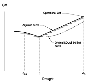
d = d S -0,6 (d S -d LS )
where: d S is the subdivision draught; and d LS is the lightship draught.
The adjusted curve is a straight line between the GM used in the model test at the subdivision draught and the intersection of the original SOLAS 90 curve and draught d.
Paragraph 4 — Procedure for experiments U.K.
4.1. Wave spectra U.K.
The JONSWAP spectrum should be used as this describes fetch- and duration- limited seas which correspond to the majority of conditions world wide. In this respect it is important that not only the peak period of the wave train is verified but also that the zero crossing period is correct.
It is required that for every test run the wave spectrum is recorded and documented. Measurements for this recording should be taken at the probe closest to the wave making machine.
It is also required that the model is instrumented so that its motions (roll, heave and pitch) as well as its attitude (heel, sinkage and trim) are monitored and recorded through-out the test.
It has been found that it is not practical to set absolute limits for significant wave heights, peak periods and zero crossing periods of the model wave spectra. An acceptable margin has therefore been introduced.
4.2. To avoid interference of the mooring system with the ship dynamics, the towing carriage (to which the mooring system is attached) should follow the model at its actual drifting speed. In a sea state with irregular waves the drift speed will not be constant; a constant carriage speed would result in low frequency, large amplitude drift oscillations, which may affect the model behaviour. U.K.
4.3. A sufficient number of tests in different wave trains is necessary to ensure statistical reliability, i.e. the objective is to determine with a high degree of confidence that an unsafe ship will capsize in the selected conditions. A minimum number of 10 runs is considered to provide a reasonable level of reliability. U.K.
Paragraph 5 — Survival criteria U.K.
The contents of this paragraph are considered self-explanatory.
Paragraph 6 — Test approval U.K.
The following documents are to be part of the report to the administration:
damage stability calculations for worst SOLAS and mid-ship damage (if different);
general arrangement drawing of the model together with details of construction and instrumentation;
inclining experiment and measurements of radii of gyration;
nominal and measured wave spectra (at the three different locations for a representative realisation and for the tests with the model from the probe closest to the wave maker);
representative record of model motions, attitude and drift;
relevant video recordings.
Note: U.K.
All tests must be witnessed by the administration.]