ANNEX IIIU.K. CONDITIONS OF EQUIVALENCE OF A SUSPENSION TO AIR-SUSPENSION
1.This Annex lays down the technical conditions relating to the equivalence of a suspension to air-suspension for vehicle driving axle(s).U.K.
2.In order to be recognised as equivalent to air suspension, a suspension shall comply with the following requirements:U.K.
During free transient low-frequency vertical oscillation of the sprung mass above a driving axle or group of axles, the measured frequency and damping with the suspension carrying its maximum load shall fall within the limits defined in points 2.3 to 2.6
Each axle shall be fitted with hydraulic dampers. On groups of axles, the dampers shall be positioned to minimise the oscillation of the groups of axles.
The mean damping ratio Dm shall be more than 20 % of critical damping for the suspension in its normal condition with hydraulic dampers in place and operating.
The damping ratio Dr of the suspension with all hydraulic dampers removed or incapacitated shall be not more than 50 % of Dm.
The frequency of the sprung mass above the driving axle or group of axles in a free transient vertical oscillation shall not be higher than 2,0 Hz.
The test procedures for measuring the frequency and damping shall be laid down in point 3.
3. Test procedure U.K.
3.1. Frequency and damping U.K.
3.1.1.The free oscillation of the sprung mass shall be given by the following equation:U.K.

Where
‘M’ is the sprung mass (kg),
‘Z’ is the vertical displacement of the sprung mass (m),
‘C’ is the total damping coefficient (N.s/m) and
‘K’ is the total vertical stiffness between the road surface and the sprung mass (N/m).
3.1.2.The frequency of oscillation (‘F’ in Hz) of the sprung mass shall be given by the following equation:U.K.

3.1.3.The damping is critical when C = CoU.K.
where:

The damping ratio as a fraction of critical is C/Co.
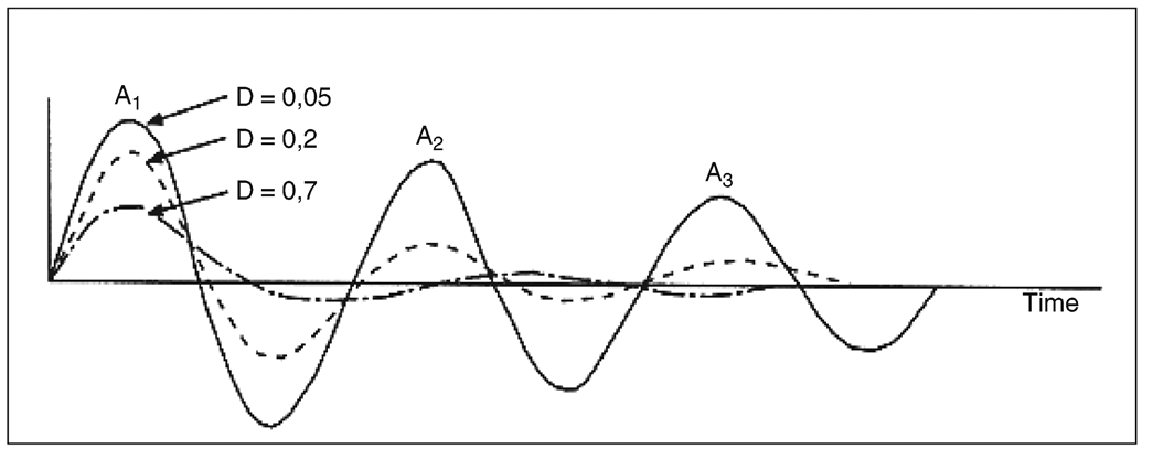
3.1.4.During free transient oscillation of the sprung mass the vertical motion of the mass will follow a damped sinusoidal path (Figure 2). The frequency can be estimated by measuring the time for as many cycles of oscillation as can be observed. The damping can be estimated by measuring the heights of successive peaks of the oscillation in the same direction.U.K.
3.1.5.If the peak amplitudes of the first and second cycles of the oscillation are A 1 and A2, then the damping ratio D is given by the following equation:U.K.

‘ln’ being the natural logarithm of the amplitude ratio.
3.2. Test procedure U.K.
To establish by test the damping ratio Dm, the damping ratio Dr, with hydraulic dampers removed, and the frequency F of the suspension, the loaded vehicle shall be either:
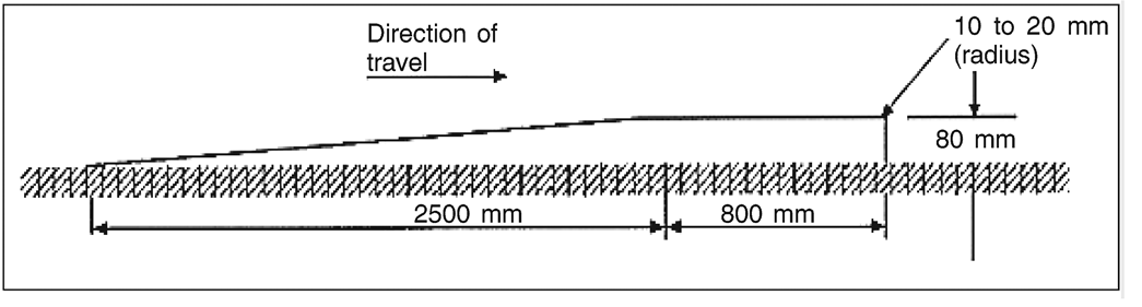
driven at low speed (5 km/h ± 1 km/h) over an 80 mm step with the profile shown in Figure 1. The transient oscillation to be analysed for frequency and damping occurs after the wheels of the driving axle have left the step;
pulled down by its chassis so that the driving axle load is 1,5 times its maximum static value. The vehicle held down is suddenly released and the subsequent oscillation analysed;
pulled up by its chassis so that the sprung mass is lifted by 80 mm above the driving axle. The vehicle held up is suddenly dropped and the subsequent oscillation analysed;
subjected to other procedures insofar as it has been proved by the manufacturer, to the satisfaction of the technical service, that they are equivalent.
3.3. Test equipment of the vehicle and loading conditions U.K.
3.3.1The vehicle shall be fitted with a vertical displacement transducer between driving axle and chassis, directly above the driving axle. From the trace, the time interval between the first and second compression peaks shall be measured to obtain the damping.U.K.
For twin driving groups of axles, vertical displacement transducers shall be fitted between each driving axle and the chassis directly above it.