- Y Diweddaraf sydd Ar Gael (Diwygiedig)
- Gwreiddiol (Fel y’i mabwysiadwyd gan yr UE)
Commission Regulation (EU) 2017/2400Dangos y teitl llawn
Commission Regulation (EU) 2017/2400 of 12 December 2017 implementing Regulation (EC) No 595/2009 of the European Parliament and of the Council as regards the determination of the CO2 emissions and fuel consumption of heavy-duty vehicles and amending Directive 2007/46/EC of the European Parliament and of the Council and Commission Regulation (EU) No 582/2011 (Text with EEA relevance)
You are here:

Pa Fersiwn
Rhagor o Adnoddau
PDF o Fersiynau Diwygiedig
- ddiwygiedig 01/09/20203.68 MB
- ddiwygiedig 01/03/20193.55 MB
Legislation originating from the EU
When the UK left the EU, legislation.gov.uk published EU legislation that had been published by the EU up to IP completion day (31 December 2020 11.00 p.m.). On legislation.gov.uk, these items of legislation are kept up-to-date with any amendments made by the UK since then.


Mae hon yn eitem o ddeddfwriaeth sy’n deillio o’r UE
Mae unrhyw newidiadau sydd wedi cael eu gwneud yn barod gan y tîm yn ymddangos yn y cynnwys a chyfeirir atynt gydag anodiadau.Ar ôl y diwrnod ymadael bydd tair fersiwn o’r ddeddfwriaeth yma i’w gwirio at ddibenion gwahanol. Y fersiwn legislation.gov.uk yw’r fersiwn sy’n weithredol yn y Deyrnas Unedig. Y Fersiwn UE sydd ar EUR-lex ar hyn o bryd yw’r fersiwn sy’n weithredol yn yr UE h.y. efallai y bydd arnoch angen y fersiwn hon os byddwch yn gweithredu busnes yn yr UE. EUR-Lex Y fersiwn yn yr archif ar y we yw’r fersiwn swyddogol o’r ddeddfwriaeth fel yr oedd ar y diwrnod ymadael cyn cael ei chyhoeddi ar legislation.gov.uk ac unrhyw newidiadau ac effeithiau a weithredwyd yn y Deyrnas Unedig wedyn. Mae’r archif ar y we hefyd yn cynnwys cyfraith achos a ffurfiau mewn ieithoedd eraill o EUR-Lex. The EU Exit Web Archive legislation_originated_from_EU_p3
Status:
EU_status_warning_original_version
This legislation may since have been updated - see the latest available (revised) version
4.Testing procedure for axles
4.1Test conditions
4.1.1Ambient temperature
The temperature in the test cell shall be maintained to 25 °C ± 10 °C. The ambient temperature shall be measured within a distance of 1 m to the axle housing. Forced heating of the axle may only be applied by an external oil conditioning system as described in 4.1.5.
4.1.2Oil temperature
The oil temperature shall be measured at the centre of the oil sump or at any other suitable point in accordance with good engineering practice. In case of external oil conditioning, alternatively the oil temperature can be measured in the outlet line from the axle housing to the conditioning system within 5 cm downstream the outlet. In both cases the oil temperature shall not exceed 70 °C.
4.1.3Oil quality
Only recommended factory fill oils as specified by the axle manufacturer shall be used for the measurement. In the case of testing different gear ratio variants with one axle housing, new oil shall be filled in for each single measurement.
4.1.4Oil viscosity
If different oils with multiple viscosity grades are specified for the factory fill, the manufacturer shall choose the oil with the highest viscosity grade for performing the measurements on the parent axle.
If more than one oil within the same viscosity grade is specified within one axle family as factory fill oil, the applicant may choose one oil of these for the measurement related to certification.
4.1.5Oil level and conditioning
The oil level or filling volume shall be set to the maximum level as defined in the manufacturer's maintenance specifications.
An external oil conditioning and filtering system is permitted. The axle housing may be modified for the inclusion of the oil conditioning system.
The oil conditioning system shall not be installed in a way which would enable changing oil levels of the axle in order to raise efficiency or to generate propulsion torques in accordance with good engineering practice.
4.2Test set-up
For the purpose of the torque loss measurement different test set-ups are permitted as described in paragraph 4.2.3 and 4.2.4.
4.2.1Axle installation
In case of a tandem axle, each axle shall be measured separately. The first axle with longitudinal differential shall be locked. The output shaft of drive-through axles shall be installed freely rotatable.
4.2.2Installation of torque meters
4.2.2.1For a test setup with two electric machines, the torque meters shall be installed on the input flange and on one wheel end while the other one is locked.
4.2.2.2For a test setup with three electric machines, the torque meters shall be installed on the input flange and on each wheel end.
4.2.2.3Half shafts of different lengths are permitted in a two machine set-up in order to lock the differential and to ensure that both wheel ends are turning.
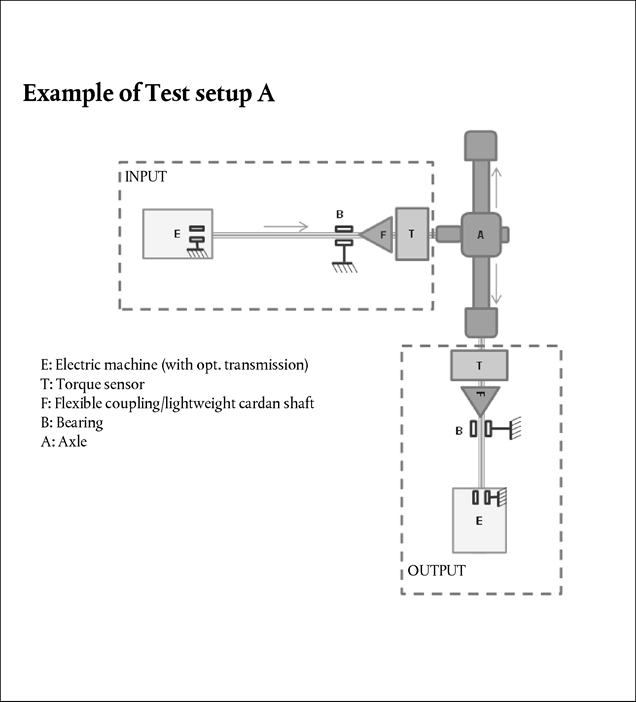
4.2.3Test set-up ‘Type A’
A test set-up considered ‘Type A’ consists of a dynamometer on the axle input side and at least one dynamometer on the axle output side(s). Torque measuring devices shall be installed on the axle input- and output- side(s). For type A set-ups with only one dynamometer on the output side, the free rotating end of the axle shall be locked.
To avoid parasitic losses, the torque measuring devices shall be positioned as close as possible to the axle input- and output- side(s) being supported by appropriate bearings.
Additionally mechanical isolation of the torque sensors from parasitic loads of the shafts, for example by installation of additional bearings and a flexible coupling or lightweight cardan shaft between the sensors and one of these bearings can be applied. Figure 1 shows an example for a test test-up of Type A in a two dynamometer lay-out.
For Type A test set-up configurations the manufacturer shall provide an analysis of the parasitic loads. Based on this analysis the approval authority shall decide about the maximum influence of parasitic loads. However the value ipara cannot be lower than 10 %.
Figure 1 Example of Test set-up ‘Type A’
4.2.4Test set-up ‘Type B’
Any other test set-up configuration is called test set-up Type B. The maximum influence of parasitic loads ipara for those configurations shall be set to 100 %.
Lower values for ipara may be used in agreement with the approval authority.
4.3Test procedure
To determine the torque loss map for an axle, the basic torque loss map data shall be measured and calculated as specified in paragraph 4.4. The torque loss results shall be complemented in accordance with 4.4.8 and formatted in accordance with Appendix 6 for the further processing by Vehicle Energy Consumption calculation Tool.
4.3.1Measurement equipment
The calibration laboratory facilities shall comply with the requirements of either ISO/TS 16949, ISO 9000 series or ISO/IEC 17025. All laboratory reference measurement equipment, used for calibration and/or verification, shall be traceable to national (international) standards.
4.3.1.1Torque measurement
The torque measurement uncertainty shall be calculated and included as described in paragraph 4.4.7.
The sample rate of the torque sensors shall be in accordance with 4.3.2.1.
4.3.1.2Rotational speed
The uncertainty of the rotational speed sensors for the measurement of input and output speed shall not exceed ± 2 rpm.
4.3.1.3Temperatures
The uncertainty of the temperature sensors for the measurement of the ambient temperature shall not exceed ± 1 °C.
The uncertainty of the temperature sensors for the measurement of the oil temperature shall not exceed ± 0,5 °C.
4.3.2Measurement signals and data recording
The following signals shall be recorded for the purpose of the calculation of the torque losses:
(i)
Input and output torques [Nm]
(ii)
Input and/or output rotational speeds [rpm]
(iii)
Ambient temperature [°C]
(iv)
Oil temperature [°C]
(v)
Temperature at the torque sensor
4.3.2.1The following minimum sampling frequencies of the sensors shall be applied:
Torque: 1 kHz
Rotational speed: 200 Hz
Temperatures: 10 Hz
4.3.2.2The recording rate of the data used to determine the arithmetic mean values of each grid point shall be 10 Hz or higher. The raw data do not need to be reported.
Signal filtering may be applied in agreement with the approval authority. Any aliasing effect shall be avoided.
4.3.3Torque range:
The extent of the torque loss map to be measured is limited to:
either an output torque of 10 kNm
or an input torque of 5 kNm
or the maximum engine power tolerated by the manufacturer for a specific axle or in case of multiple driven axles according to the nominal power distribution.
4.3.3.1The manufacturer may extend the measurement up to 20 kNm output torque by means of linear extrapolation of torque losses or by performing measurements up to 20 kNm output torque with steps of 2 000 Nm. For this additional torque range another torque sensor at the output side with a maximum torque of 20 kNm (2-machine layout) or two 10 kNm sensors (3-machine layout) shall be used.
If the radius of the smallest tire is reduced (e.g. product development) after completing the measurement of an axle or when the physic boundaries of the test stand are reached (e.g. by product development changes), the missing points may be extrapolated by the manufacturer out of the existing map. The extrapolated points shall not exceed more than 10 % of all points in the map and the penalty for these points is 5 % torque loss to be added on the extrapolated points.
4.3.3.2Output torque steps to be measured:
250 Nm < Tout < 1 000 Nm
:
250 Nm steps
1 000 Nm ≤ Tout ≤ 2 000 Nm
:
500 Nm steps
2 000 Nm ≤ Tout ≤ 10 000 Nm
:
1 000 Nm steps
Tout > 10 000 Nm
:
2 000 Nm steps
If the maximum input torque is limited by the manufacturer, the last torque step to be measured is the one below this maximum without consideration of any losses. In that case an extrapolation of the torque loss shall be applied up to the torque corresponding to the manufacturer's limitation with the linear regression based on the torque steps of the corresponding speed step.
4.3.4Speed range
The range of test speeds shall comprise from 50 rpm wheel speed to the maximum speed. The maximum test speed to be measured is defined by either the maximum axle input speed or the maximum wheel speed, whichever of the following conditions is reached first:
4.3.4.1
The maximum applicable axle input speed may be limited to design specification of the axle.
4.3.4.2
The maximum wheel speed is measured under consideration of the smallest applicable tire diameter at a vehicle speed of 90 km/h for trucks and 110 km/h for coaches. If the smallest applicable tire diameter is not defined, paragraph 4.3.4.1 shall apply.
4.3.5Wheel speed steps to be measured
The wheel speed step width for testing shall be 50 rpm.
4.4Measurement of torque loss maps for axles
4.4.1Testing sequence of the torque loss map
For each speed step the torque loss shall be measured for each output torque step starting from 250 Nm upward to the maximum and downward to the minimum. The speed steps can be run in any order.
Interruptions of the sequence for cooling or heating purposes are permitted.
4.4.2Measurement duration
The measurement duration for each single grid point shall be 5-15 seconds.
4.4.3Averaging of grid points
The recorded values for each grid point within the 5-15 seconds interval according to point 4.4.2. shall be averaged to an arithmetic mean.
All four averaged intervals of corresponding speed and torque grid points from both sequences measured each upward and downward shall be averaged to an arithmetic mean and result into one torque loss value.
4.4.4The torque loss (at input side) of the axle shall be calculated by

where:
Tloss
=
Torque loss of the axle at the input side [Nm]
Tin
=
Input torque [Nm]
igear
=
Axle gear ratio [-]
Tout
=
Output torque [Nm]
4.4.5Measurement validation
4.4.5.1The averaged speed values per grid point (20 s interval) shall not deviate from the setting values by more than ± 5 rpm for the output speed.
4.4.5.2The averaged output torque values as described under 4.4.3 for each grid point shall not deviate more than ± 20 Nm or ± 1 % from the torque set point for the according grid point, whichever is the higher value.
4.4.5.3If the above specified criteria are not met the measurement is void. In this case, the measurement for the entire affected speed step shall be repeated. After passing the repeated measurement, the data shall be consolidated.
4.4.6Uncertainty calculation
The total uncertainty UT,loss of the torque loss shall be calculated based on the following parameters:
i.
Temperature effect
ii.
Parasitic loads
iii.
Uncertainty (incl. sensitivity tolerance, linearity, hysteresis and repeatability)
The total uncertainty of the torque loss (UT,loss) is based on the uncertainties of the sensors at 95 % confidence level. The calculation shall be done for each applied sensor (e.g. three machine lay out: UT,in, UT,out,1, UTout,2) as the square root of the sum of squares (‘Gaussian law of error propagation’).


wpara = senspara * ipara
where:
UT,in/out
=
Uncertainty of input/output torque loss measurement separately for input and output torque; [Nm]
igear
=
Axle gear ratio [-]
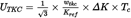
UTKC
=
Uncertainty by temperature influence on current torque signal; [Nm]
wtkc
=
Temperature influence on current torque signal per Kref, declared by sensor manufacturer; [%]
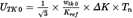
UTK0
=
Uncertainty by temperature influence on zero torque signal (related to nominal torque) [Nm]
wtk0
=
Temperature influence on zero torque signal per Kref (related to nominal torque), declared by sensor manufacturer; [%]
Kref
=
Reference temperature span for tkc and tk0, declared by sensor manufacturer; [°C]
ΔK
=
Absolute difference in sensor temperature measured at torque sensor between calibration and measurement; If the sensor temperature cannot be measured, a default value of ΔK = 15 K shall be used [°C]
Tc
=
Current/measured torque value at torque sensor; [Nm]
Tn
=
Nominal torque value of torque sensor; [Nm]
Ucal
=
Uncertainty by torque sensor calibration; [Nm]
wcal
=
Relative calibration uncertainty (related to nominal torque); [%]
kcal
=
calibration advancement factor (if declared by sensor manufacturer, otherwise = 1)
Upara
=
Uncertainty by parasitic loads; [Nm]
wpara
=
senspara * ipara
Relative influence of forces and bending torques caused by misalignment
senspara
=
Maximum influence of parasitic loads for specific torque sensor declared by sensor manufacturer [%]; if no specific value for parasitic loads is declared by the sensor manufacturer, the value shall be set to 1,0 %
ipara
=
Maximum influence of parasitic loads for specific torque sensor depending on test set-up as indicated in section 4.2.3 and 4.2.4 of this annex.
4.4.7Assessment of total uncertainty of the torque loss
In the case the calculated uncertainties UT,in/out are below the following limits, the reported torque loss Tloss,rep shall be regarded as equal to the measured torque loss Tloss .
UT,in : 7,5 Nm or 0,25 % of the measured torque, whichever allowed uncertainty value is higher
UT,out : 15 Nm or 0,25 % of the measured torque, whichever allowed uncertainty value is higher
In the case of higher calculated uncertainties, the part of the calculated uncertainty exceeding the above specified limits shall be added to Tloss for the reported torque loss Tloss,rep as follows:
If the limits of UT,in are exceeded:
Tloss,rep = Tloss + ΔUTin
ΔUT,in = MIN((UT,in – 0,25 % * Tc) or (UT,in – 7,5 Nm))
If limits of UT,out out are exceeded:
Tloss,rep = Tloss + ΔUT,out/igear
ΔUT,out = MIN((UT,out – 0,25 % * Tc) or (UT,out – 15Nm))
where:
UT,in/out
=
Uncertainty of input/output torque loss measurement separately for input and output torque; [Nm]
igear
=
Axle gear ratio [-]
ΔUT
=
The part of the calculated uncertainty exceeding the specified limits
4.4.8Complement of torque loss map data
4.4.8.1If the torque values exceed the upper range limit linear extrapolation shall be applied. For the extrapolation the slope of linear regression based on all measured torque points for the corresponding speed step shall be applied.
4.4.8.2For the output torque range values below 250 Nm the torque loss values of the 250 Nm point shall be applied.
4.4.8.3For 0 rpm wheel speed rpm the torque loss values of the 50 rpm speed step shall be applied.
4.4.8.4For negative input torques (e.g. overrun, free rolling), the torque loss value measured for the related positive input torque shall be applied.
4.4.8.5In case of a tandem axle, the combined torque loss map for both axles shall be calculated out of the test results for the single axles.
Tloss,rep,tdm = Tloss,rep, 1 + Tloss,rep, 2
Options/Help
Print Options
PrintThe Whole Regulation
PrintThe Whole Annex
PrintThis Division only
You have chosen to open the Whole Regulation
The Whole Regulation you have selected contains over 200 provisions and might take some time to download. You may also experience some issues with your browser, such as an alert box that a script is taking a long time to run.
Would you like to continue?
You have chosen to open Schedules only
Y Rhestrau you have selected contains over 200 provisions and might take some time to download. You may also experience some issues with your browser, such as an alert box that a script is taking a long time to run.
Would you like to continue?
Mae deddfwriaeth ar gael mewn fersiynau gwahanol:
Y Diweddaraf sydd Ar Gael (diwygiedig):Y fersiwn ddiweddaraf sydd ar gael o’r ddeddfwriaeth yn cynnwys newidiadau a wnaed gan ddeddfwriaeth ddilynol ac wedi eu gweithredu gan ein tîm golygyddol. Gellir gweld y newidiadau nad ydym wedi eu gweithredu i’r testun eto yn yr ardal ‘Newidiadau i Ddeddfwriaeth’.
Gwreiddiol (Fel y’i mabwysiadwyd gan yr UE): Mae'r wreiddiol version of the legislation as it stood when it was first adopted in the EU. No changes have been applied to the text.
Dewisiadau Agor
Dewisiadau gwahanol i agor deddfwriaeth er mwyn gweld rhagor o gynnwys ar y sgrin ar yr un pryd
Rhagor o Adnoddau
Gallwch wneud defnydd o ddogfennau atodol hanfodol a gwybodaeth ar gyfer yr eitem ddeddfwriaeth o’r tab hwn. Yn ddibynnol ar yr eitem ddeddfwriaeth sydd i’w gweld, gallai hyn gynnwys:
- y PDF print gwreiddiol y fel adopted version that was used for the EU Official Journal
- rhestr o newidiadau a wnaed gan a/neu yn effeithio ar yr eitem hon o ddeddfwriaeth
- pob fformat o’r holl ddogfennau cysylltiedig
- slipiau cywiro
- dolenni i ddeddfwriaeth gysylltiedig ac adnoddau gwybodaeth eraill
Rhagor o Adnoddau
Defnyddiwch y ddewislen hon i agor dogfennau hanfodol sy’n cyd-fynd â’r ddeddfwriaeth a gwybodaeth am yr eitem hon o ddeddfwriaeth. Gan ddibynnu ar yr eitem o ddeddfwriaeth sy’n cael ei gweld gall hyn gynnwys:
- y PDF print gwreiddiol y fel adopted fersiwn a ddefnyddiwyd am y copi print
- slipiau cywiro
liciwch ‘Gweld Mwy’ neu ddewis ‘Rhagor o Adnoddau’ am wybodaeth ychwanegol gan gynnwys
- rhestr o newidiadau a wnaed gan a/neu yn effeithio ar yr eitem hon o ddeddfwriaeth
- manylion rhoi grym a newid cyffredinol
- pob fformat o’r holl ddogfennau cysylltiedig
- dolenni i ddeddfwriaeth gysylltiedig ac adnoddau gwybodaeth eraill
 Mae’r holl gynnwys ar gael dan Drwydded Llywodraeth Agored v3.0 ac eithrio ble nodir yn wahanol. Yn ychwanegol mae’r safle hwn â chynnwys sy’n deillio o EUR-Lex, a ailddefnyddiwyd dan delerau Penderfyniad y Comisiwn 2011/833/EU ar ailddefnyddio dogfennau o sefydliadau’r UE. Am ragor o wybodaeth gweler ddatganiad cyhoeddus Swyddfa Gyhoeddiadau’r UE ar ailddefnyddio.