
ANNEX IU.K. CLASSIFICATION OF VEHICLES IN VEHICLE GROUPS
1.Classification of the vehicles for the purpose of this RegulationU.K.
1.1Classification of vehicles of category NU.K.
Table 1
Vehicle groups for vehicles of category N
| a in these vehicle classes tractors are treated as rigids but with specific curb weight of tractor T = Tractor R = Rigid & standard body T1, T2 = Standard trailers ST = Standard semitrailer D = Standard dolly | |||||||||||
| (*) EMS - European Modular System | |||||||||||
| Description of elements relevant to the classification in vehicle groups | Vehicle group | Allocation of mission profile and vehicle configuration | Standard body allocation | ||||||||
|---|---|---|---|---|---|---|---|---|---|---|---|
| Axle configuration | Chassis configuration | Technically permissible maximum laden mass (tons) | Long haul | Long haul (EMS) | Regional delivery | Regional delivery (EMS) | Urban delivery | Municipal utility | Construction | ||
| 4 × 2 | Rigid | > 3,5 – < 7,5 | (0) | ||||||||
| Rigid (or tractor)a | 7,5 – 10 | 1 | R | R | B1 | ||||||
| Rigid (or tractor)a | > 10 – 12 | 2 | R + T1 | R | R | B2 | |||||
| Rigid (or tractor)a | > 12 – 16 | 3 | R | R | B3 | ||||||
| Rigid | > 16 | 4 | R + T2 | R | R | B4 | |||||
| Tractor | > 16 | 5 | T + ST | T + ST + T2 | T + ST | T + ST + T2 | |||||
| 4 × 4 | Rigid | 7,5 – 16 | (6) | ||||||||
| Rigid | > 16 | (7) | |||||||||
| Tractor | > 16 | (8) | |||||||||
| 6 × 2 | Rigid | all weights | 9 | R + T2 | R + D + ST | R | R + D + ST | R | B5 | ||
| Tractor | all weights | 10 | T + ST | T + ST + T2 | T + ST | T + ST + T2 | |||||
| 6 × 4 | Rigid | all weights | 11 | R + T2 | R + D + ST | R | R + D + ST | R | R | B5 | |
| Tractor | all weights | 12 | T + ST | T + ST + T2 | T + ST | T + ST + T2 | R | ||||
| 6 × 6 | Rigid | all weights | (13) | ||||||||
| Tractor | all weights | (14) | |||||||||
| 8 × 2 | Rigid | all weights | (15) | ||||||||
| 8 × 4 | Rigid | all weights | 16 | R | (generic weight + CdxA) | ||||||
| 8 × 6 8 × 8 | Rigid | all weights | (17) | ||||||||
ANNEX IIU.K. REQUIREMENTS AND PROCEDURES RELATED TO THE OPERATION OF THE SIMULATION TOOL
1.The processes to be set up by the vehicle manufacturer with a view to the operation of the simulation toolU.K.
1.1.The manufacturer shall set up at least the following processes:U.K.
A data management system covering sourcing, storing, handling and retrieving of the input information and input data for the simulation tool as well as handling certificates on the CO2 emissions and fuel consumption related properties of a component families, separate technical unit families and system families. The data management system shall at least:
ensure application of correct input information and input data to specific vehicle configurations
ensure correct calculation and application of standard values;
verify by means of comparing cryptographic hashes that the input files of component families, separate technical unit families and system families which are used for the simulation corresponds to the input data of the component families, separate technical unit families and system families for which the certification has been granted;
include a protected database for storing the input data relating to the component families, separate technical unit families or system families and the corresponding certificates of the CO2 emissions and fuel consumption related properties;
ensure correct management of the changes of specification and updates of components, separate technical units and systems;
enable tracing of the components, separate technical units and systems after the vehicle is produced.
A data management system covering retrieving of the input information and input data and calculations by means of the simulation tool and storing of the output data. The data management system shall at least:
ensure a correct application of cryptographic hashes;
include a protected database for storing the output data;
Process for consulting the dedicated electronic distribution platform referred to in Article 5(2) and Article 10(1) and (2), as well as downloading and installing the latest versions of the simulation tool.
Appropriate training of staff working with the simulation tool.
2.Assessment by the approval authorityU.K.
2.1.The approval authority shall verify whether the processes set out in point 1 related to the operation of the simulation tool have been set up.U.K.
The approval authority shall also verify the following:
the functioning of the processes set out in points 1.1.1, 1.1.2 and 1.1.3 and the application of the requirement set out in point 1.1.4;
that the processes used during the demonstration are applied in the same manner in all the production facilities manufacturing the vehicle group concerned;
the completeness of the description of the data and process flows of operations related to the determination of the CO2 emissions and fuel consumption of the vehicles.
For the purpose of point (a) of the second paragraph, The verification shall include determination of the CO2 emissions and fuel consumption of at leaste one vehicle from each of the vehicle groups for which the licence has been applied for.
Appendix 1 MODEL OF AN INFORMATION DOCUMENT FOR THE PURPOSES OF OPERATING THE SIMULATION TOOL WITH A VIEW TO DETERMINING THE CO2 EMISSIONS AND FUEL CONSUMPTION OF NEW VEHICLES
SECTION IU.K.
1Name and address of manufacturer:U.K.
2Assembly plants for which the processes referred to in point 1 of Annex II of Regulation (EU) 2017/2400 have been set up with a view to the operation of the simulation tool:U.K.
3Vehicle groups covered:U.K.
4Name and address of the manufacturer's representative (if any)U.K.
SECTION IIU.K.
1.Additional informationU.K.
1.1.Data and process flow handling description (e.g. flow chart)U.K.
1.2Description of quality management processU.K.
1.3Additional quality management certificates (if any)U.K.
1.4Description of simulation tool data sourcing, handling and storageU.K.
1.5Additional documents (if any)U.K.
2.Date: …U.K.
3.Signature: …U.K.
Appendix 2 MODEL OF A LICENCE TO OPERATE THE SIMULATION TOOL WITH A VIEW TO DETERMINING CO2 EMISSIONS AND FUEL CONSUMPTION OF NEW VEHICLES
Maximum format: A4 (210 × 297 mm)U.K.
LICENCE TO OPERATE THE SIMULATION TOOL WITH A VIEW TO DETERMINING CO2 EMISSIONS AND FUEL CONSUMPTION OF NEW VEHICLES U.K.
of the licence to operate simulation tool with regard to Regulation (EC) No 595/2009 as implemented by Regulation (EU) 2017/2400.
Licence number:
Reason for extension: …
SECTION IU.K.
0.1Name and address of manufacturer:U.K.
0.2Assembly plants for which the processes referred to in point 1 of Annex II of Commission Regulation (EU) 2017/2400 have been set up with a view to the operation of the simulation toolU.K.
0.3Vehicle groups covered:U.K.
SECTION IIU.K.
1.Additional informationU.K.
1.1Assessment report performed by an approval authorityU.K.
1.2.Data and process flow handling description (e.g. flow chart)U.K.
1.3.Description of quality management processU.K.
1.4.Additional quality management certificates (if any)U.K.
1.5.Description of simulation tool data sourcing, handling and storageU.K.
1.6Additional documents (if any)U.K.
2.Approval authority responsible for carrying out the assessmentU.K.
3.Date of the assessment reportU.K.
4.Number of assessment report reportU.K.
5.Remarks (if any): see AddendumU.K.
6.PlaceU.K.
7.DateU.K.
8.SignatureU.K.
ANNEX IIIU.K. INPUT INFORMATION RELATING TO THE CHARACTERISTIC OF THE VEHICLE
1.IntroductionU.K.
This Annex describes the list of parameters to be provided by the vehicle manufacturer as input to the simulation tool. The applicable XML schema as well as example data are available at the dedicated electronic distribution platform.
2.DefinitionsU.K.
‘Parameter ID’: Unique identifier as used in ‘Vehicle Energy Consumption calculation Tool’ for a specific input parameter or set of input data
‘Type’: Data type of the parameter
sequence of characters in ISO8859-1 encoding
sequence of characters in ISO8859-1 encoding, no leading/trailing whitespace
date and time in UTC time in the format: YYYY-MM-DDTHH:MM:SSZ with italic letters denoting fixed characters e.g. ‘2002-05-30T09:30:10Z’
value with an integral data type, no leading zeros, e.g. ‘1800’
fractional number with exactly X digits after the decimal sign (‘.’) and no leading zeros e.g. for ‘double, 2’: ‘2345.67’; for ‘double, 4’: ‘45.6780’
‘Unit’ … physical unit of the parameter
‘corrected actual mass of the vehicle’ shall mean the mass as specified under the ‘actual mass of the vehicle’ in accordance with Commission Regulation (EC) No 1230/2012(1) with an exception for the tank(s) which shall be filled to at least 50 % of its or their capacity/ies, without superstructure and corrected by the additional weight of the non-installed standard equipment as specified in point 4.3 and the mass of a standard body, standard semi-trailer or standard trailer to simulate the complete vehicle or complete vehicle-(semi-)trailer combination.
All parts that are mounted on and above the main frame are regarded as superstructure parts if they are only installed for facilitating a superstructure, independent of the necessary parts for in running order conditions.
3.Set of input parametersU.K.
Table 1
Input parameters ‘Vehicle/General’
| Parameter name | Parameter ID | Type | Unit | Description/Reference |
|---|---|---|---|---|
| Manufacturer | P235 | token | [-] | |
| ManufacturerAddress | P252 | token | [-] | |
| Model | P236 | token | [-] | |
| VIN | P238 | token | [-] | |
| Date | P239 | dateTime | [-] | Date and time when the component-hash is created |
| LegislativeClass | P251 | string | [-] | Allowed values: ‘N3’ |
| VehicleCategory | P036 | string | [-] | Allowed values: ‘Rigid Truck’, ‘Tractor’ |
| AxleConfiguration | P037 | string | [-] | Allowed values: ‘4×2’, ‘6×2’, ‘6×4’, ‘8×4’ |
| CurbMassChassis | P038 | int | [kg] | |
| GrossVehicleMass | P041 | int | [kg] | |
| IdlingSpeed | P198 | int | [1/min] | |
| RetarderType | P052 | string | [-] | Allowed values: ‘None’, ‘Losses included in Gearbox’, ‘Engine Retarder’, ‘Transmission Input Retarder’, ‘Transmission Output Retarder’ |
| RetarderRatio | P053 | double, 3 | [-] | |
| AngledriveType | P180 | string | [-] | Allowed values: ‘None’, ‘Losses included in Gearbox’, ‘Separate Angledrive’ |
| PTOShaftsGearWheels | P247 | string | [-] | Allowed values: ‘none’, ‘only the drive shaft of the PTO’, ‘drive shaft and/or up to 2 gear wheels’, ‘drive shaft and/or more than 2 gear wheels’, ‘only one engaged gearwheel above oil level’ |
| PTOOtherElements | P248 | string | [-] | Allowed values: ‘none’, ‘shift claw, synchronizer, sliding gearwheel’, ‘multi-disc clutch’, ‘multi-disc clutch, oil pump’ |
| CertificationNumberEngine | P261 | token | [-] | |
| CertificationNumberGearbox | P262 | token | [-] | |
| CertificationNumberTorqueconverter | P263 | token | [-] | |
| CertificationNumberAxlegear | P264 | token | [-] | |
| CertificationNumberAngledrive | P265 | token | [-] | |
| CertificationNumberRetarder | P266 | token | [-] | |
| CertificationNumberTyre | P267 | token | [-] | |
| CertificationNumberAirdrag | P268 | token | [-] |
Table 2
Input parameters ‘Vehicle/AxleConfiguration’ per wheel axle
| Parameter name | Parameter ID | Type | Unit | Description/Reference |
|---|---|---|---|---|
| TwinTyres | P045 | boolean | [-] | |
| AxleType | P154 | string | [-] | Allowed values: ‘VehicleNonDriven’, ‘VehicleDriven’ |
| Steered | P195 | boolean |
Table 3
Input parameters ‘Vehicle/Auxiliaries’
| Parameter name | Parameter ID | Type | Unit | Description/Reference |
|---|---|---|---|---|
| Fan/Technology | P181 | string | [-] | Allowed values: ‘Crankshaft mounted - Electronically controlled visco clutch’, ‘Crankshaft mounted - Bimetallic controlled visco clutch’, ‘Crankshaft mounted - Discrete step clutch’, ‘Crankshaft mounted - On/off clutch’, ‘Belt driven or driven via transm. - Electronically controlled visco clutch’, ‘Belt driven or driven via transm. - Bimetallic controlled visco clutch’, ‘Belt driven or driven via transm. - Discrete step clutch’, ‘Belt driven or driven via transm. - On/off clutch’, ‘Hydraulic driven - Variable displacement pump’, ‘Hydraulic driven - Constant displacement pump’, ‘Electrically driven - Electronically controlled’ |
| SteeringPump/Technology | P182 | string | [-] | Allowed values: ‘Fixed displacement’, ‘Fixed displacement with elec. control’, ‘Dual displacement’, ‘Variable displacement mech. controlled’, ‘Variable displacement elec. controlled’, ‘Electric’ Separate entry for each steered wheel axle required |
| ElectricSystem/Technology | P183 | string | [-] | Allowed values: ‘Standard technology’, ‘Standard technology - LED headlights, all’ |
| PneumaticSystem/Technology | P184 | string | [-] | Allowed values: ‘Small’, ‘Small + ESS’, ‘Small + visco clutch’ , ‘Small + mech. clutch’, ‘Small + ESS + AMS’, ‘Small + visco clutch + AMS’, ‘Small + mech. clutch + AMS’, ‘Medium Supply 1-stage’, ‘Medium Supply 1-stage + ESS’, ‘Medium Supply 1-stage + visco clutch’ , ‘Medium Supply 1-stage + mech. clutch’, ‘Medium Supply 1-stage + ESS + AMS’, ‘Medium Supply 1-stage + visco clutch + AMS’, ‘Medium Supply 1-stage + mech. clutch + AMS’, ‘Medium Supply 2-stage’, ‘Medium Supply 2-stage + ESS’, ‘Medium Supply 2-stage + visco clutch’ , ‘Medium Supply 2-stage + mech. clutch’, ‘Medium Supply 2-stage + ESS + AMS’, ‘Medium Supply 2-stage + visco clutch + AMS’, ‘Medium Supply 2-stage + mech. clutch + AMS’, ‘Large Supply’, ‘Large Supply + ESS’, ‘Large Supply + visco clutch’ , ‘Large Supply + mech. clutch’, ‘Large Supply + ESS + AMS’, ‘Large Supply + visco clutch + AMS’, ‘Large Supply + mech. clutch + AMS’; ‘Vacuum pump’ |
| HVAC/Technology | P185 | string | [-] | Allowed values: ‘Default’ |
Table 4
Input parameters ‘Vehicle/EngineTorqueLimits’ per gear (optional)
| Parameter name | Parameter ID | Type | Unit | Description/Reference |
|---|---|---|---|---|
| Gear | P196 | integer | [-] | only gear numbers need to be specified where vehicle related engine torque limits according to point 6 are applicable |
| MaxTorque | P197 | integer | [Nm] |
4.Vehicle massU.K.
4.1The vehicle mass used as input for the simulation tool shall be the corrected actual mass of the vehicle.U.K.
This corrected actual mass shall be based on vehicles equipped in such a way that they are compliant to all regulatory acts of Annex IV and Annex XI to Directive 2007/46/EC applicable to the particular vehicle class.
4.2If not all the standard equipment is installed, the manufacturer shall add the weight of the following construction elements to the corrected actual mass of the vehicle:U.K.
Front under-run protection in accordance with Regulation (EC) No 661/2009 of the European Parliament and of the Council(2)
Rear under-run protection in accordance with Regulation (EC) No 661/2009 of the European Parliament and of the Council
Lateral protection in accordance with Regulation (EC) No 661/2009 of the European Parliament and of the Council
Fifth wheel in accordance with Regulation (EC) No 661/2009 of the European Parliament and of the Council
4.3The weight of the construction elements referred to in point 4.2 shall be the following:U.K.
For vehicles of groups 1, 2 and 3
(a) Front under-ride protection45 kg
(b) Rear under-ride protection40 kg
(c) Lateral protection8,5 kg/m × wheel base [m] – 2,5 kg
(d) Fifth wheel210 kg
For vehicles of groups 4, 5, 9 to 12 and 16
(a) Front under-ride protection50 kg
(b) Rear under-ride protection45 kg
(c) Lateral protection14 kg/m × wheel base [m] – 17 kg
(d) Fifth wheel210 kg
5.Hydraulically and mechanically driven axlesU.K.
In case of vehicles equipped with:
a hydraulically driven axles, the axle shall be treated as a non-drivable one and the manufacturer shall not take it into consideration for establishing an axle configuration of a vehicle;
a mechanically driven axles, the axle shall be treated as a drivable one and the manufacturer shall take it into consideration for establishing an axle configuration of a vehicle;
6.Gear dependent engine torque limits set by vehicle controlU.K.
For the highest 50 % of the gears (e.g. for gears 7 to 12 of a 12 gear transmission) the vehicle manufacturer may declare a gear dependent maximum engine torque limit which is not higher than 95 % of the maximum engine torque.
7.Vehicle specific engine idling speedU.K.
7.1.The engine idling speed has to be declared in VECTO for each individual vehicle. This declared vehicle engine idling shall be equal or higher than specified in the engine input data approval.U.K.
ANNEX IVU.K. MODEL OF THE MANUFACTURER'S RECORDS FILE AND OF THE CUSTOMER INFORMATION FILE
PART IU.K. Vehicle CO2 emissions and fuel consumption – Manufacturer's records file
The manufacturer's records file will be produced by the simulation tool and shall at least contain the following information:
1.Vehicle, component, separate technical unit and systems dataU.K.
1.1.Vehicle dataU.K.
1.1.1.Name and address of manufacturerU.K.
1.1.2.Vehicle modelU.K.
1.1.3.Vehicle identification number (VIN) …U.K.
1.1.4.Vehicle category (N1 N2, N3, M1, M2, M3) …U.K.
1.1.5.Axle configuration …U.K.
1.1.6.Max. gross vehicle weight (t) …U.K.
1.1.7.Vehicle group in accordance with Table 1 …U.K.
1.1.8.Corrected actual curb mass (kg) …U.K.
1.2.Main engine specificationsU.K.
1.2.1.Engine modelU.K.
1.2.2.Engine certification number …U.K.
1.2.3.Engine rated power (kW) …U.K.
1.2.4.Engine idling speed (1/min) …U.K.
1.2.5.Engine rated speed (1/min) …U.K.
1.2.6.Engine capacity (ltr) …U.K.
1.2.7.Engine reference fuel type (diesel/LPG/CNG …) …U.K.
1.2.8.Hash of the fuel map file/document …U.K.
1.3.Main transmission specificationsU.K.
1.3.1.Transmission modelU.K.
1.3.2.Transmission certification number …U.K.
1.3.3.Main option used for generation of loss maps (Option1/Option2/Option3/Stnadard values) …:U.K.
1.3.4.Transmission type (SMT, AMT, APT-S,APT-P) …U.K.
1.3.5.Nr. of gears …U.K.
1.3.6.Transmission ratio final gear …U.K.
1.3.7.Retarder type …U.K.
1.3.8.Power take off (yes/no) …U.K.
1.3.9.Hash of the efficiency map file/document …U.K.
1.4.Retarder specificationsU.K.
1.4.1.Retarder modelU.K.
1.4.2.Retarder certification number …U.K.
1.4.3.Certification option used for generation of a loss map (standard values/measurement) …U.K.
1.4.4.Hash of the efficiency map file/document …U.K.
1.5.Torque converter specificationU.K.
1.5.1.Torque converter modelU.K.
1.5.2.Torque converter certification number …U.K.
1.5.3.Certification option used for generation of a loss map (standard values/measurement) …U.K.
1.5.4.Hash of the efficiency map file/document …U.K.
1.6.Angle drive specificationsU.K.
1.6.1.Angle drive modelU.K.
1.6.2.Axle certification number …U.K.
1.6.3.Certification option used for generation of a loss map (standard values/measurement) …U.K.
1.6.4.Angle drive ratio …U.K.
1.6.5.Hash of the efficiency map file/document …U.K.
1.7.Axle specificationsU.K.
1.7.1.Axle model …U.K.
1.7.2.Axle certification number …U.K.
1.7.3.Certification option used for generation of a loss map (standard values/measurement) …U.K.
1.7.4.Axle type (e.g. standard single driven axle) …U.K.
1.7.5.Axle ratio …U.K.
1.7.6.Hash of the efficiency map file/document …U.K.
1.8.AerodynamicsU.K.
1.8.1.ModelU.K.
1.8.2.Certification option used for generation of CdxA (standard values /measurement) …U.K.
1.8.3.CdxA Certification number (if applicable) …U.K.
1.8.4.CdxA value …U.K.
1.8.5.Hash of the efficiency map file/document …U.K.
1.9.Main tyre specificationsU.K.
1.9.1.Tyre dimension axle 1 …U.K.
1.9.2.Tyre certification number …U.K.
1.9.3.Specific RRC of all tyres on axle 1 …U.K.
1.9.4.Tyre dimension axle 2 …U.K.
1.9.5.Twin axle (yes/no) axle 2 …U.K.
1.9.6.Tyre certification number …U.K.
1.9.7.Specific RRC of all tyres on axle 2 …U.K.
1.9.8.Tyre dimension axle 3 …U.K.
1.9.9.Twin axle (yes/no) axle 3 …U.K.
1.9.10.Tyre certification number …U.K.
1.9.11.Specific RRC of all tyres on axle 3 …U.K.
1.9.12.Tyre dimension axle 4 …U.K.
1.9.13.Twin axle (yes/no) axle 4 …U.K.
1.9.14.Tyre certification number …U.K.
1.9.15.Specific RRC of all tyres on axle 4 …U.K.
1.10.Main auxiliary specificationsU.K.
1.10.1.Engine cooling fan technology …U.K.
1.10.2.Steering pump technology …U.K.
1.10.3.Electric system technology …U.K.
1.10.4.Pneumatic system technology …U.K.
1.11.Engine torque limitationsU.K.
1.11.1.Engine torque limit at gear 1 (% of max engine torque) …U.K.
1.11.2.Engine torque limit at gear 2 (% of max engine torque) …U.K.
1.11.3.Engine torque limit at gear 3 (% of max engine torque) …U.K.
1.11.4.Engine torque limit at gear … (% of max engine torque)U.K.
2.Mission profile and loading dependent valuesU.K.
2.1.Simulation parameters (for each profile/load/fuel combination)U.K.
2.1.1.Mission profile (long haul/regional/urban/municipal/construction) …U.K.
2.1.2.Load (as defined in the simulation tool) (kg) …U.K.
2.1.3.Fuel (diesel/petrol/LPG/CNG/…) …U.K.
2.1.4.Total vehicle mass in simulation (kg) …U.K.
2.2.Vehicle driving performance and information for simulation quality checkU.K.
2.2.1.Average speed (km/h) …U.K.
2.2.2.Minimum instantaneous speed (km/h) …U.K.
2.2.3.Maximum instantaneous speed (km/h) …U.K.
2.2.4.Maximum deceleration (m/s2) …U.K.
2.2.5.Maximum acceleration (m/s2) …U.K.
2.2.6.Full load percentage on driving time …U.K.
2.2.7.Total number of gear shifts …U.K.
2.2.8.Total driven distance (km) …U.K.
2.3.Fuel and CO2 resultsU.K.
2.3.1.Fuel consumption (g/km) …U.K.
2.3.2.Fuel consumption (g/t-km) …U.K.
2.3.3.Fuel consumption (g/p-km) …U.K.
2.3.4.Fuel consumption (g/m3-km) …U.K.
2.3.5.Fuel consumption (l/100km) …U.K.
2.3.6.Fuel consumption (l/t-km) …U.K.
2.3.7.Fuel consumption (l/p-km) …U.K.
2.3.8.Fuel consumption (l/m3-km) …U.K.
2.3.9.Fuel consumption (MJ/km) …U.K.
2.3.10.Fuel consumption (MJ/t-km) …U.K.
2.3.11.Fuel consumption (MJ/p-km) …U.K.
2.3.12.Fuel consumption (MJ/m3-km) …U.K.
2.3.13.CO2 (g/km) …U.K.
2.3.14.CO2 (g/t-km) …U.K.
2.3.15.CO2 (g/p-km) …U.K.
2.3.16.CO2 (g/m3-km) …U.K.
3.Software and user informationU.K.
3.1.Software and user informationU.K.
3.1.1.Simulation tool version (X.X.X) …U.K.
3.1.2.Date and time of the simulationU.K.
3.1.3.Hash of simulation tool input information and input data …U.K.
3.1.4.Hash of simulation tool result …U.K.
PART IIU.K. Vehicle CO2 emissions and fuel consumption - Customer information file
1.Vehicle, component, separate technical unit and systems dataU.K.
1.1.Vehicle dataU.K.
1.1.1.Vehicle identification number (VIN) …U.K.
1.1.2.Vehicle category (N1 N2, N3, M1, M2, M3) …U.K.
1.1.3.Axle configuration …U.K.
1.1.4.Max. gross vehicle weight (t) …U.K.
1.1.5.Vehicle's group …U.K.
1.1.6.Name and address of manufacturer …U.K.
1.1.7.Make (trade name of manufacturer) …U.K.
1.1.8.Corrected actual curb mass (kg) …U.K.
1.2.Component, separate technical unit and systems dataU.K.
1.2.1.Engine rated power (kW) …U.K.
1.2.2.Engine capacity (ltr) …U.K.
1.2.3.Engine reference fuel type (diesel/LPG/CNG…) …U.K.
1.2.4.Transmission values (measured/standard) …U.K.
1.2.5.Transmission type (SMT, AMT, AT-S, AT-S) …U.K.
1.2.6.Nr. of gears …U.K.
1.2.7.Retarder (yes/no) …U.K.
1.2.8.Axle ratio …U.K.
1.2.9.Avarage rolling resistance coefficient (RRC) of all tyres:U.K.
PART IIIU.K. CO2 emissions and fuel consumption of the vehicle (for each payload/fuel combination)
Payload low [kg]:
| Average vehicle speed | CO2 emissions | Fuel consumption | |||||
|---|---|---|---|---|---|---|---|
| Long haul | … km/h | … g/km | … g/t-km | … g/m3-km | … l/100 km | … l/t-km | … l/m3-km |
| Long haul (EMS) | … km/h | … g/km | … g/t-km | … g/m3-km | … l/100 km | … l/t-km | … l/m3-km |
| Regional delivery | … km/h | … g/km | … g/t-km | … g/m3-km | … l/100 km | … l/t-km | … l/m3-km |
| Regional delivery (EMS) | … km/h | … g/km | … g/t-km | … g/m3-km | … l/100 km | … l/t-km | … l/m3-km |
| Urban delivery | … km/h | … g/km | … g/t-km | … g/m3-km | … l/100 km | … l/t-km | … l/m3-km |
| Municipal utility | … km/h | … g/km | … g/t-km | … g/m3-km | … l/100 km | … l/t-km | … l/m3-km |
| Construction | … km/h | … g/km | … g/t-km | … g/m3-km | … l/100 km | … l/t-km | … l/m3-km |
Payload representative [kg]:
| Average vehicle speed | CO2 emissions | Fuel consumption | |||||
|---|---|---|---|---|---|---|---|
| Long haul | … km/h | … g/km | … g/t-km | … g/m3-km | … l/100 km | … l/t-km | … l/m3-km |
| Long haul (EMS) | … km/h | … g/km | … g/t-km | … g/m3-km | … l/100 km | … l/t-km | … l/m3-km |
| Regional delivery | … km/h | … g/km | … g/t-km | … g/m3-km | … l/100 km | … l/t-km | … l/m3-km |
| Regional delivery (EMS) | … km/h | … g/km | … g/t-km | … g/m3-km | … l/100 km | … l/t-km | … l/m3-km |
| Urban delivery | … km/h | … g/km | … g/t-km | … g/m3-km | … l/100 km | … l/t-km | … l/m3-km |
| Municipal utility | … km/h | … g/km | … g/t-km | … g/m3-km | … l/100 km | … l/t-km | … l/m3-km |
| Construction | … km/h | … g/km | … g/t-km | … g/m3-km | … l/100 km | … l/t-km | … l/m3-km |
| Software and user information | Simulation tool version | [X.X.X] |
| Date and time of the simulation | [-] |
Cryptographic hash of the output file:
ANNEX VU.K. VERIFYING ENGINE DATA
1.IntroductionU.K.
The engine test procedure described in this Annex shall produce input data relating to engines for the simulation tool.
2.DefinitionsU.K.
For the purposes of this Annex the definitions according to UN/ECE Regulation 49 Rev.06 and, in addition to these, the following definitions shall apply:
‘engine CO2-family’ means a manufacturer's grouping of engines, as defined in paragraph 1 of Appendix 3;
‘CO2-parent engine’ means an engine selected from an engine CO2-family as specified in Appendix 3;
‘NCV’ means net calorific value of a fuel as specified in paragraph 3.2;
‘specific mass emissions’ means the total mass emissions divided by the total engine work over a defined period expressed in g/kWh;
‘specific fuel consumption’ means the total fuel consumption divided by the total engine work over a defined period expressed in g/kWh;
‘FCMC’ means fuel consumption mapping cycle;
‘Full load’ means the delivered engine torque/power at a certain engine speed when the engine is operated at maximum operator demand.
The definitions in paragraphs 3.1.5 and 3.1.6. of Annex 4 to UN/ECE Regulation 49 Rev.06 shall not apply.
3.General requirementsU.K.
The calibration laboratory facilities shall comply with the requirements of either ISO/TS 16949, ISO 9000 series or ISO/IEC 17025. All laboratory reference measurement equipment, used for calibration and/or verification, shall be traceable to national or international standards.
Engines shall be grouped into engine CO2-families defined in accordance with Appendix 3. Paragraph 4.1 explains which testruns shall be performed for the purpose of certification of one specific engine CO2-family.
3.1Test conditionsU.K.
All testruns performed for the purpose of certification of one specific engine CO2-family defined in accordance with Appendix 3 to this Annex shall be conducted on the same physical engine and without any changes to the setup of the engine dynamometer and the engine system, apart from the exceptions defined in paragraph 4.2 and Appendix 3.
3.1.1Laboratory test conditionsU.K.
The tests shall be conducted under ambient conditions meeting the following conditions over the whole testrun:
The parameter fa describing the laboratory test conditions, determined in accordance with paragraph 6.1 of Annex 4 to UN/ECE Regulation 49 Rev.06, shall be within the following limits: 0,96 ≤ fa ≤ 1,04.
The absolute temperature (Ta) of the engine intake air expressed in Kelvin, determined in accordance with paragraph 6.1 of Annex 4 to UN/ECE Regulation 49 Rev.06 shall be within the following limits: 283 K ≤ Ta ≤ 303 K.
The atmospheric pressure expressed in kPa, determined in accordance with paragraph 6.1 of Annex 4 to UN/ECE Regulation 49 Rev.06 shall be within the following limits: 90 kPa ≤ ps ≤ 102 kPa.
If tests are performed in test cells that are able to simulate barometric conditions other than those existing in the atmosphere at the specific test site, the applicable fa value shall be determined with the simulated values of atmospheric pressure by the conditioning system. The same reference value for the simulated atmospheric pressure shall be used for the intake air and exhaust path and all other relevant engine systems. The actual value of the simulated atmospheric pressure for the intake air and exhaust path and all other relevant engine systems shall be within the limits specified in subpoint (3).
In cases where the ambient pressure in the atmosphere at the specific test site exceeds the upper limit of 102 kPa, tests in accordance with this Annex may still be performed. In this case tests shall be performed with the specific ambient air pressure in the atmosphere.
In cases where the test cell has the ability to control temperature, pressure and/or humidity of engine intake air independent of the atmospheric conditions the same settings for those parameters shall be used for all testruns performed for the purpose of certification of one specific engine CO2-family defined in accordance with Appendix 3 to this Annex.
3.1.2Engine installationU.K.
The test engine shall be installed in accordance with paragraphs 6.3 to 6.6 of Annex 4 to UN/ECE Regulation 49 Rev.06.
If auxiliaries/equipment necessary for operating the engine system are not installed as required in accordance with paragraph 6.3 of Annex 4 to UN/ECE Regulation 49 Rev.06, all measured engine torque values shall be corrected for the power required for driving these components for the purpose of this Annex in accordance with paragraph 6.3 of Annex 4 to UN/ECE Regulation 49 Rev.06.
The power consumption of the following engine components resulting in the engine torque required for driving these engine components shall be determined in accordance with Appendix 5 to this Annex:
fan
electrically powered auxiliaries/equipment necessary for operating the engine system
3.1.3Crankcase emissionsU.K.
In the case of a closed crankcase, the manufacturer shall ensure that the engine's ventilation system does not permit the emission of any crankcase gases into the atmosphere. If the crankcase is of an open type, the emissions shall be measured and added to the tailpipe emissions, following the provisions set out in paragraph 6.10. of Annex 4 to UN/ECE Regulation 49 Rev.06.
3.1.4Engines with charge air-coolingU.K.
During all testruns the charge air cooling system used on the test bed shall be operated under conditions which are representative for in-vehicle application at reference ambient conditions. The reference ambient conditions are defined as 293 K for air temperature and 101,3 kPa for pressure.
The laboratory charge air cooling for tests according to this regulation should comply with the provisions specified in paragraph 6.2 of Annex 4 to UN/ECE Regulation 49 Rev.06.
3.1.5Engine cooling systemU.K.
During all testruns the engine cooling system used on the test bed shall be operated under conditions which are representative for in-vehicle application at reference ambient conditions. The reference ambient conditions are defined as 293 K for air temperature and 101,3 kPa for pressure.
The engine cooling system should be equipped with thermostats according to the manufacturer specification for vehicle installation. If either a non-operational thermostat is installed or no thermostat is used, subpoint (3) shall apply. The setting of the cooling system shall be performed in accordance with subpoint (4).
If no thermostat is used or a non-operational thermostat is installed, the test bed system shall reflect the behavior of the thermostat under all test conditions. The setting of the cooling system shall be performed in accordance with subpoint (4).
The engine coolant flow rate (or alternatively the pressure differential across the engine side of the heat exchanger) and the engine coolant temperature shall be set to a value representative for in-vehicle application at reference ambient conditions when the engine is operated at rated speed and full load with the engine thermostat in fully open position. This setting defines the coolant reference temperature. For all testruns performed for the purpose of certification of one specific engine within one engine CO2-family, the cooling system setting shall not be changed, neither on the engine side nor on the test bed side of the cooling system. The temperature of the test bed side cooling medium should be kept resonably constant by good engineering judgement. The cooling medium on the test bed side of the heat exchanger shall not exceed the nominal thermostat opening temperatur downstream of the heat exchanger.
For all testruns performed for the purpose of certification of one specific engine within one engine CO2-family the engine coolant temperature shall be maintained between the nominal value of the thermostat opening temperature declared by the manufacturer and the coolant reference temperature in accordance with subpoint (4) as soon as the engine coolant has reached the declared thermostat opening temperature after engine cold start.
For the WHTC coldstart test performed in accordance with paragraph 4.3.3, the specific initial conditions are specified in paragraphs 7.6.1. and 7.6.2 of Annex 4 to UN/ECE Regulation 49 Rev.06. If simulation of the thermostat behaviour in accordance with subpoint (3) is applied, there shall be no coolant flow across the heat exchanger as long as the engine coolant has not reached the declared nominal thermostat opening temperature after cold start.
3.2FuelsU.K.
The respective reference fuel for the engine systems under test shall be selected from the fuel types listed in Table 1. The fuel properties of the reference fuels listed in Table 1 shall be those specified in Annex IX to Commission Regulation (EU) No 582/2011.
To ensure that the same fuel is used for all testruns performed for the purpose of certification of one specific engine CO2-family no refill of the tank or switch to another tank supplying the engine system shall occur. Exceptionally a refill or switch may be allowed if it can be ensured that the replacement fuel has exactly the same properties as the fuel used before (same production batch).
The NCV for the fuel used shall be determined by two separate measurements in accordance with the respective standards for each fuel type defined in Table 1. The two separate measurements shall be performed by two different labs independent from the manufacturer applying for certification. The lab performing the measurements shall comply with the requirements of ISO/IEC 17025. The approval authority shall ensure that the fuel sample used for determination of the NCV is taken from the batch of fuel used for all testruns.
If the two separate values for the NCV are deviating by more than 440 Joule per gram fuel, the values determined shall be void and the measurement campaign shall be repeated.
The mean value of the two separate NCV that are not deviating by more than 440 Joule per gram fuel shall be documented in MJ/kg rounded to 3 places to the right of the decimal point in accordance with ASTM E 29-06.
For gas fuels the standards for determining the NCV according to Table 1 contain the calculation of the calorific value based on the fuel composition. The gas fuel composition for determining the NCV shall be taken from the analysis of the reference gas fuel batch used for the certification tests. For the determination of the gas fuel composition used for determining the NCV only one single analysis by a lab independent from the manufacturer applying for certification shall be performed. For gas fuels the NCV shall be determined based on this single analysis instead of a mean value of two separate measurements.
Table 1
Reference fuels for testing
| Fuel type / engine type | Reference fuel type | Standard used for determination of NCV |
|---|---|---|
| Diesel / CI | B7 | at least ASTM D240 or DIN 59100-1 (ASTM D4809 is recommended) |
| Ethanol / CI | ED95 | at least ASTM D240 or DIN 59100-1 (ASTM D4809 is recommended) |
| Petrol / PI | E10 | at least ASTM D240 or DIN 59100-1 (ASTM D4809 is recommended) |
| Ethanol / PI | E85 | at least ASTM D240 or DIN 59100-1 (ASTM D4809 is recommended) |
| LPG / PI | LPG Fuel B | ASTM 3588 or DIN 51612 |
| Natural Gas / PI | G25 | ISO 6976 or ASTM 3588 |
3.3LubricantsU.K.
The lubricating oil for all testruns performed in accordance with this Annex shall be a commercially available oil with unrestricted manufacturer approval under normal in-service conditions as defined in paragraph 4.2 of Annex 8 to UN/ECE Regulation 49 Rev.06. Lubricants for which the usage is restricted to certain special operation conditions of the engine system or having an unusually short oil change interval shall not be used for the purpose of testruns in accordance with this Annex. The commercially available oil shall not be modified by any means and no additives shall be added.
All testruns performed for the purpose of certification of the CO2 emissions and fuel consumption related properties of one specific engine CO2-family shall be performed with the same type of lubricating oil.
3.4Fuel flow measurement systemU.K.
All fuel flows consumed by the whole engine system shall be captured by the fuel flow measurement system. Additional fuel flows not directly supplied to the combustion process in the engine cylinders shall be included in the fuel flow signal for all testruns performed. Additional fuel injectors (e.g. cold start devices) not necessary for the operation of the engine system shall be disconnected from the fuel supply line during all testruns performed.
3.5Measurement equipment specificationsU.K.
The measurement equipment shall meet the requirements of paragraph 9 of Annex 4 to UN/ECE Regulation 49 Rev.06.
Notwithstanding the requirements defined in paragraph 9 of Annex 4 to UN/ECE Regulation 49 Rev.06, the measurement systems listed in Table 2 shall meet the limits defined in Table 2.
Table 2
Requirements of measurement systems
| a ‘Accuracy’ means the deviation of the analyzer reading from a reference value which is traceable to a national or international standard. | ||||||
| b ‘Rise time’ means the difference in time between the 10 percent and 90 percent response of the final analyzer reading (t90 – t10). | ||||||
| c The ‘max calibration’ values shall be 1,1 times the maximum predicted value expected during all testruns for the respective measurement system. | ||||||
| Linearity | ||||||
|---|---|---|---|---|---|---|
| Measurement system | Intercept| xmin × (a1 – 1) + a0 | | Slopea1 | Standard error of estimate SEE | Coefficient of determinationr2 | Accuracya | Rise timeb |
| Engine speed | ≤ 0,2 % max calibrationc | 0,999 - 1,001 | ≤ 0,1 % max calibrationc | ≥ 0,9985 | 0,2 % of reading or 0,1 % of max. calibrationc of speed whichever is larger | ≤ 1 s |
| Engine torque | ≤ 0,5 % max calibrationc | 0,995 - 1,005 | ≤ 0,5 % max calibrationc | ≥ 0,995 | 0,6 % of reading or 0,3 % of max. calibrationc of torque whichever is larger | ≤ 1 s |
| Fuel mass flow for liquid fuels | ≤ 0,5 % max calibrationc | 0,995 - 1,005 | ≤ 0,5 % max calibrationc | ≥ 0,995 | 0,6 % of reading or 0,3 % of max. calibrationc of flow whichever is larger | ≤ 2 s |
| Fuel mass flow for gaseous fuels | ≤ 1 % max calibrationc | 0,99 - 1,01 | ≤ 1 % max calibrationc | ≥ 0,995 | 1 % of reading or 0,5 % of max. calibrationc of flow whichever is larger | ≤ 2 s |
| Electrical Power | ≤ 1 % max calibrationc | 0,98 - 1,02 | ≤ 2 % max calibrationc | ≥ 0,990 | n.a. | ≤ 1 s |
| Current | ≤ 1 % max calibrationc | 0,98 - 1,02 | ≤ 2 % max calibrationc | ≥ 0,990 | n.a. | ≤ 1 s |
| Voltage | ≤ 1 % max calibrationc | 0,98 - 1,02 | ≤ 2 % max calibrationc | ≥ 0,990 | n.a. | ≤ 1 s |
‘xmin’, used for calculation of the intercept value in Table 2, shall be 0,9 times the minimum predicted value expected during all testruns for the respective measurement system.
The signal delivery rate of the measurement systems listed in Table 2, except for the fuel mass flow measurement system, shall be at least 5 Hz (≥ 10 Hz recommended). The signal delivery rate of the fuel mass flow measurement system shall be at least 2 Hz.
All measurement data shall be recorded with a sample rate of at least 5 Hz (≥ 10 Hz recommended).
3.5.1Measurement equipment verificationU.K.
A verification of the demanded requirements defined in Table 2 shall be performed for each measurement system. At least 10 reference values between xmin and the ‘max calibration’ value defined in accordance with paragraph 3.5 shall be introduced to the measurement system and the response of the measurement system shall be recorded as measured value.
For the linearity verification the measured values shall be compared to the reference values by using a least squares linear regression in accordance with paragraph A.3.2 of Appendix 3 to Annex 4 to UN/ECE Regulation 49 Rev.06.
4.Testing procedureU.K.
All measurement data shall be determined in accordance with Annex 4 to UN/ECE Regulation 49 Rev.06, unless stated otherwise in this Annex.
4.1Overview of testruns to be performedU.K.
Table 3 gives an overview of all testruns to be performed for the purpose of certification of one specific engine CO2-family defined in accordance with Appendix 3.
The fuel consumption mapping cycle in accordance with paragraph 4.3.5 and the recording of the engine motoring curve in accordance with paragraph 4.3.2 shall be omitted for all other engines except the CO2-parent engine of the engine CO2-family.
In the case that upon request of the manufacturer the provisions defined in Article 15(5) of this Regulation are applied, the fuel consumption mapping cycle in accordance with paragraph 4.3.5 and the recording of the engine motoring curve in accordance with paragraph 4.3.2 shall be performed additionally for that specific engine.
Table 3
Overview of testruns to be performed
| Testrun | Reference to paragraph | Required to be run for CO2-parent engine | Required to be run for other engines within CO2-family |
|---|---|---|---|
| Engine full load curve | 4.3.1 | yes | yes |
| Engine motoring curve | 4.3.2 | yes | no |
| WHTC test | 4.3.3 | yes | yes |
| WHSC test | 4.3.4 | yes | yes |
| Fuel consumption mapping cycle | 4.3.5 | yes | no |
4.2Allowed changes to the engine systemU.K.
Changing of the target value for the engine idle speed controller to a lower value in the electronic control unit of the engine shall be allowed for all testruns in which idle operation occurs, in order to prevent interference between the engine idle speed controller and the test bed speed controller.
4.3TestrunsU.K.
4.3.1Engine full load curveU.K.
The engine full load curve shall be recorded in accordance with paragraphs 7.4.1. to 7.4.5. of Annex 4 to UN/ECE Regulation 49 Rev.06.
4.3.2Engine motoring curveU.K.
The recording of the engine motoring curve in accordance with this paragraph shall be omitted for all other engines except the CO2-parent engine of the engine CO2-family defined in accordance with Appendix 3. In accordance with paragraph 6.1.3 the engine motoring curve recorded for the CO2-parent engine of the engine CO2-family shall also be applicable to all engines within the same engine CO2-family.
In the case that upon request of the manufacturer the provisions defined in Article 15(5) of this Regulation are applied, the recording of the engine motoring curve shall be performed additionally for that specific engine.
The engine motoring curve shall be recorded in accordance with option (b) in paragraph 7.4.7. of Annex 4 to UN/ECE Regulation 49 Rev.06. This test shall determine the negative torque required to motor the engine between maximum and minimum mapping speed with minimum operator demand.
The test shall be continued directly after the full load curve mapping according to paragraph 4.3.1. At the request of the manufacturer, the motoring curve may be recorded separately. In this case the engine oil temperature at the end of the full load curve testrun performed in accordance with paragraph 4.3.1 shall be recorded and the manufacturer shall prove to the satisfaction of the an approval authority, that the engine oil temperature at the starting point of the motoring curve meets the aforementioned temperature within ± 2 K.
At the start of the testrun for the engine motoring curve the engine shall be operated with minimum operator demand at maximum mapping speed defined in paragraph 7.4.3. of Annex 4 to UN/ECE Regulation 49 Rev.06. As soon as the motoring torque value has stabilized within ± 5 % of its mean value for at least 10 seconds, the data recording shall start and the engine speed shall be decreased at an average rate of 8 ± 1 min– 1/s from maximum to minimum mapping speed, which are defined in paragraph 7.4.3. of Annex 4 to UN/ECE Regulation 49 Rev.06.
4.3.3WHTC testU.K.
The WHTC test shall be performed in accordance with Annex 4 to UN/ECE Regulation 49 Rev.06. The weighted emission test results shall meet the applicable limits defined in Regulation (EC) No 595/2009.
The engine full load curve recorded in accordance with paragraph 4.3.1 shall be used for the denormalization of the reference cycle and all calculations of reference values performed in accordance with paragraphs 7.4.6, 7.4.7 and 7.4.8 of Annex 4 to UN/ECE Regulation 49 Rev.06.
4.3.3.1Measurement signals and data recordingU.K.
In addition to the provisions defined in Annex 4 to UN/ECE Regulation 49 Rev.06 the actual fuel mass flow consumed by the engine in accordance with paragraph 3.4 shall be recorded.
4.3.4WHSC testU.K.
The WHSC test shall be performed in accordance with Annex 4 to UN/ECE Regulation 49 Rev.06. The emission test results shall meet the applicable limits defined in Regulation (EC) No 595/2009.
The engine full load curve recorded in accordance with paragraph 4.3.1 shall be used for the denormalization of the reference cycle and all calculations of reference values performed in accordance with paragraphs 7.4.6, 7.4.7 and 7.4.8 of Annex 4 to UN/ECE Regulation 49 Rev.06.
4.3.4.1Measurement signals and data recordingU.K.
In addition to the provisions defined in Annex 4 to UN/ECE Regulation 49 Rev.06 the actual fuel mass flow consumed by the engine in accordance with paragraph 3.4 shall be recorded.
4.3.5Fuel consumption mapping cycle (FCMC)U.K.
The fuel consumption mapping cycle (FCMC) in accordance with this paragraph shall be omitted for all other engines except the CO2-parent engine of the engine CO2-family. The fuel map data recorded for the CO2-parent engine of the engine CO2-family shall also be applicable to all engines within the same engine CO2-family.
In the case that upon request of the manufacturer the provisions defined in Article 15(5) of this Regulation are applied, the fuel consumption mapping cycle shall be performed additionally for that specific engine.
The engine fuel map shall be measured in a series of steady state engine operation points, as defined according to paragraph 4.3.5.2. The metrics of this map are the fuel consumption in g/h depending on engine speed in min-1 and engine torque in Nm.
4.3.5.1Handling of interruptions during the FCMCU.K.
If an after-treatment regeneration event occurs during the FCMC for engines equipped with exhaust after-treatment systems that are regenerated on a periodic basis defined in accordance with paragraph 6.6 of Annex 4 to UN/ECE Regulation 49 Rev.06, all measurements at that engine speed mode shall be void. The regeneration event shall be completed and afterwards the procedure shall be continued as described in paragraph 4.3.5.1.1.
If an unexpected interruption, malfunction or error occurs during the FCMC, all measurements at that engine speed mode shall be void and one of the following options how to continue shall be chosen by the manufacturer:
the procedure shall be continued as described in paragraph 4.3.5.1.1
the whole FCMC shall be repeated in accordance with paragraphs 4.3.5.4 and 4.3.5.5
4.3.5.1.1Provisions for continuing the FCMCU.K.
The engine shall be started and warmed up in accordance with paragraph 7.4.1. of Annex 4 to UN/ECE Regulation 49 Rev.06. After warm-up, the engine shall be preconditioned by operating the engine for 20 minutes at mode 9, as defined in Table 1 of paragraph 7.2.2. of Annex 4 to UN/ECE Regulation 49 Rev.06.
The engine full load curve recorded in accordance with paragraph 4.3.1 shall be used for the denormalization of the reference values of mode 9 performed in accordance with paragraphs 7.4.6, 7.4.7 and 7.4.8 of Annex 4 to UN/ECE Regulation 49 Rev.06.
Directly after completion of preconditioning, the target values for engine speed and torque shall be changed linearly within 20 to 46 seconds to the highest target torque setpoint at the next higher target engine speed setpoint than the particular target engine speed setpoint where the interruption of the FCMC occurred. If the target setpoint is reached within less than 46 seconds, the remaining time up to 46 seconds shall be used for stabilization.
For stabilization the engine operation shall continue from that point in accordance with the test sequence specified in paragraph 4.3.5.5 without recording of measurement values.
When the highest target torque setpoint at the particular target engine speed setpoint where the interruption occurred is reached, the recording of measurement values shall be continued from that point on in accordance with the test sequence specified in paragraph 4.3.5.5.
4.3.5.2Grid of target setpointsU.K.
The grid of target setpoints is fixed in a normalized way and consists of 10 target engine speed setpoints and 11 target torque setpoints. Conversion of the normalized setpoint definition to the actual target values of engine speed and torque setpoints for the individual engine under test shall be based on the engine full load curve of the CO2-parent engine of the engine CO2-family defined in accordance with Appendix 3 to this Annex and recorded in accordance with paragraph 4.3.1.
4.3.5.2.1Definition of target engine speed setpointsU.K.
The 10 target engine speed setpoints are defined by 4 base target engine speed setpoints and 6 additional target engine speed setpoints.
The engine speeds nidle, nlo, npref, n95h and nhi shall be determined from the engine full load curve of the CO2-parent engine of the engine CO2-family defined in accordance with Appendix 3 to this Annex and recorded in accordance with paragraph 4.3.1 by applying the definitions of characteristic engine speeds in accordance with paragraph 7.4.6. of Annex 4 to UN/ECE Regulation 49 Rev.06.
The engine speed n57 shall be determined by the following equation:
n57 = 0,565 × (0,45 × nlo + 0,45 × npref + 0,1 × nhi – nidle) × 2,0327 + nidle
The 4 base target engine speed setpoints are defined as follows:
Base engine speed 1: nidle
Base engine speed 2: nA = n57 – 0,05 × (n95h – nidle)
Base engine speed 3: nB = n57 + 0,08 × (n95h – nidle)
Base engine speed 4: n95h
The potential distances between the speed setpoints shall be determined by the following equations:
dnidleA_44 = (nA – nidle) / 4
dnB95h_44 = (n95h – nB) / 4
dnidleA_35 = (nA – nidle) / 3
dnB95h_35 = (n95h – nB) / 5
dnidleA_53 = (nA – nidle) / 5
dnB95h_53 = (n95h – nB) / 3
The absolute values of potential deviations between the two sections shall be determined by the following equations:
dn44 = ABS(dnidleA_44 – dnB95h_44)
dn35 = ABS(dnidleA_35 – dnB95h_35)
dn53 = ABS(dnidleA_53 – dnB95h_53)
The 6 additional target engine speed setpoints shall be determined based on the smallest of the three values dn44, dn35 and dn53 in accordance with the following provisions:
If dn44 is the smallest of the three values, the 6 additional target engine speeds shall be determined by dividing each of the two ranges, one from nidle to nA and the other from nB to n95h, into 4 equidistant sections.
If dn35 is the smallest of the three values, the 6 additional target engine speeds shall be determined by dividing the range from nidle to nA into 3 equidistant sections and the range from nB to n95h, into 5 equidistant sections.
If dn53 is the smallest of the three values, the 6 additional target engine speeds shall be determined by dividing the range from nidle to nA into 5 equidistant sections and the range from nB to n95h, into 3 equidistant sections.
Figure 1 exemplarily illustrates the definition of the target engine speed setpoints according to subpoint (1) above.

4.3.5.2.2Definition of target torque setpointsU.K.
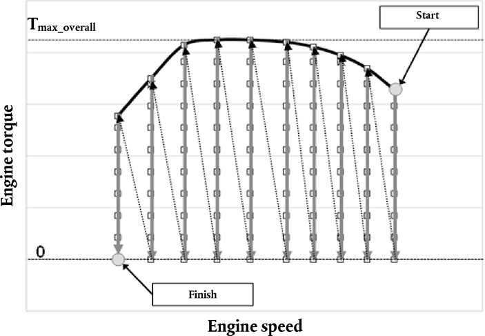
The 11 target torque setpoints are defined by 2 base target torque setpoints and 9 additional target torque setpoints. The 2 base target torque setpoints are defined by zero engine torque and the maximum engine full load of the CO2-parent engine determined in accordance with paragraph 4.3.1. (overall maximum torque Tmax_overall). The 9 additional target torque setpoints are determined by dividing the range from zero torque to overall maximum torque, Tmax_overall, into 10 equidistant sections.
All target torque setpoints at a particular target engine speed setpoint that exceed the limit value defined by the full load torque value at this particular target engine speed setpoint minus 5 percent of Tmax_overall, shall be replaced with the full load torque value at this particular target engine speed setpoint. Figure 2 exemplarily illustrates the definition of the target torque setpoints.

4.3.5.3Measurement signals and data recordingU.K.
The following measurement data shall be recorded:
engine speed
engine torque corrected in accordance with paragraph 3.1.2
fuel mass flow consumed by the whole engine system in accordance with paragraph 3.4
Gaseous pollutants according to the definitions in UN/ECE Regulation 49 Rev.06. Particulate pollutants and ammonia emissions are not required to be monitored during the FCMC testrun.
The measurement of gaseous pollutants shall be carried out in accordance with paragraphs 7.5.1, 7.5.2, 7.5.3, 7.5.5, 7.7.4, 7.8.1, 7.8.2, 7.8.4 and 7.8.5 of Annex 4 to UN/ECE Regulation 49 Rev.06.
For the purpose of paragraph 7.8.4 of Annex 4 to UN/ECE Regulation 49 Rev.06, the term ‘test cycle’ in the paragraph referred to shall be the complete sequence from preconditioning in accordance with paragraph 4.3.5.4 to ending of the test sequence in accordance with paragraph 4.3.5.5.
4.3.5.4Preconditioning of the engine systemU.K.
The dilution system, if applicable, and the engine shall be started and warmed up in accordance with paragraph 7.4.1. of Annex 4 to UN/ECE Regulation 49 Rev.06.
After warm-up is completed, the engine and sampling system shall be preconditioned by operating the engine for 20 minutes at mode 9, as defined in Table 1 of paragraph 7.2.2. of Annex 4 to UN/ECE Regulation 49 Rev.06, while simultaneously operating the dilution system.
The engine full load curve of the CO2-parent engine of the engine CO2-family and recorded in accordance with paragraph 4.3.1 shall be used for the denormalization of the reference values of mode 9 performed in accordance with paragraphs 7.4.6, 7.4.7 and 7.4.8 of Annex 4 to UN/ECE Regulation 49 Rev.06.
Directly after completion of preconditioning, the target values for engine speed and torque shall be changed linearly within 20 to 46 seconds to match the first target setpoint of the test sequence according to paragraph 4.3.5.5. If the first target setpoint is reached within less than 46 seconds, the remaining time up to 46 seconds shall be used for stabilization.
4.3.5.5Test sequenceU.K.
The test sequence consists of steady state target setpoints with defined engine speed and torque at each target setpoint in accordance with paragraph 4.3.5.2 and defined ramps to move from one target setpoint to the next.
The highest target torque setpoint at each target engine speed shall be operated with maximum operator demand.
The first target setpoint is defined at the highest target engine speed setpoint and highest target torque setpoint.
The following steps shall be performed to cover all target setpoints:
The engine shall be operated for 95 ± 3 seconds at each target setpoint. The first 55 ± 1 seconds at each target setpoint are considered as a stabilization period,. During the following period of 30 ± 1 seconds the engine speed mean value shall be controlled as follows:
The engine speed mean value shall be held at the target engine speed setpoint within ± 1 percent of the highest target engine speed.
Except for the points at full load, the engine torque mean value shall be held at the target torque setpoint within a tolerance of ± 20 Nm or ± 2 percent of the overall maximum torque, Tmax_overall, whichever is greater.
The recorded values in accordance with paragraph 4.3.5.3 shall be stored as averaged value over the period of 30 ± 1 seconds. The remaining period of 10 ± 1 seconds may be used for data post-processing and storage if necessary. During this period the engine target setpoint shall be kept.
After the measurement at one target setpoint is completed, the target value for engine speed shall be kept constant within ± 20 min– 1 of the target engine speed setpoint and the target value for torque shall be decreased linearly within 20±1 seconds to match the next lower target torque setpoint. Then the measurement shall be performed according to subpoint (1).
After the zero torque setpoint has been measured in subpoint (1), the target engine speed shall be decreased linearly to the next lower target engine speed setpoint while at the same time the target torque shall be increased linearly to the highest target torque setpoint at the next lower target engine speed setpoint within 20 to 46 seconds. If the next target setpoint is reached within less than 46 seconds, the remaining time up to 46 seconds shall be used for stabilization. Then the measurement shall be performed by starting the the stabilization procedure according to subpoint (1) and afterwards the target torque setpoints at constant target engine speed shall be adjusted according to subpoint (2).
Figure 3 illustrates the three different steps to be performed at each measurement setpoint for the test according to subpoint (1) above.

Figure 4 exemplarily illustrates the sequence of steady state measurement setpoints to be followed for the test.
4.3.5.6Data evaluation for emission monitoringU.K.
Gaseous pollutants in accordance with paragraph 4.3.5.3 shall be monitored during the FCMC. The definitions of characteristic engine speeds in accordance with paragraph 7.4.6. of Annex 4 to UN/ECE R.49.06 shall apply.
4.3.5.6.1Definition of control areaU.K.
The control area for emission monitoring during the FCMC shall be determined in accordance with paragraphs 4.3.5.6.1.1 and 4.3.5.6.1.2.
4.3.5.6.1.1Engine speed range for the control areaU.K.
The engine speed range for the control area shall be defined based on the engine full load curve of the CO2-parent engine of the engine CO2-family defined in accordance with Appendix 3 to this Annex and recorded in accordance with paragraph 4.3.1.
The control area shall include all engine speeds greater than or equal to the 30th percentile cumulative speed distribution, determined from all engine speeds including idle speed sorted in ascending order, over the hotstart WHTC test cycle performed in accordance with paragraph 4.3.3 (n30) for the engine full load curve referred to the subpoint (1).
The control area shall include all engine speeds lower than or equal to nhi determined from the engine full load curve referred to in the subpoint (1)
4.3.5.6.1.2Engine torque and power range for the control areaU.K.
The lower boundary of the engine torque range for the control area shall be defined based on the engine full load curve of the engine with the lowest rating of all engines within the engine CO2-family and recorded in accordance with paragraph 4.3.1.
The control area shall include all engine load points with a torque value greater than or equal to 30 percent of the maximum torque value determined from the engine full load curve referred to in subpoint (1).
Notwithstanding the provisions of subpoint (2), speed and torque points below 30 percent of the maximum power value, determined from the engine full load curve referred to in subpoint (1), shall be excluded from the control area.
Notwithstanding the provisions of subpoints (2) and (3), the upper boundary of the control area shall be based on the engine full load curve of the CO2-parent engine of the engine CO2-family defined in accordance with Appendix 3 to this Annex and recorded in accordance with paragraph 4.3.1. The torque value for each engine speed determined from the engine full load curve of the CO2-parent engine shall be increased by 5 percent of the overall maximum torque, Tmax_overall, defined in accordance with paragraph 4.3.5.2.2. The modified increased engine full load curve of the CO2-parent engine shall be used as upper boundary of the control area.
Figure 5 exemplarily illustrates the definition of the engine speed, torque and power range for the control area.

4.3.5.6.2Definition of the grid cellsU.K.
The control area defined in accordance with paragraph 4.3.5.6.1 shall be divided into a number of grid cells for emission monitoring during the FCMC.
The grid shall comprise of 9 cells for engines with a rated speed less than 3 000 min– 1 and 12 cells for engines with a rated speed greater than or equal to 3 000 min– 1. The grids shall be defined in accordance with the following provisions:
The outer boundaries of the grids are aligned to the control area defined according to paragraph 4.3.5.6.1.
2 vertical lines spaced at equal distance between engine speeds n30 and 1,1 times n95h for 9 cell grids, or 3 vertical lines spaced at equal distance between engine speeds n30 and 1,1 times n95h for 12 cell grids.
2 lines spaced at equal distance of engine torque (i.e. 1/3) at each vertical line of engine speed defined by subpoints (1) and (2)
All engine speed values in min-1 and all torque values in Newtonmeters defining the boundaries of the grid cells shall be rounded to 2 places to the right of the decimal point in accordance with ASTM E 29-06.
Figure 6 exemplarily illustrates the definition of the grid cells for the control area in the case of 9 cell grid.

4.3.5.6.3Calculation of specific mass emissionsU.K.
The specific mass emissions of the gaseous pollutants shall be determined as average value for each grid cell defined in accordance with paragraph 4.3.5.6.2. The average value for each grid cell shall be determined as arithmetical mean value of the specific mass emissions over all engine speed and torque points measured during the FCMC located within the same grid cell.
The specific mass emissions of the single engine speed and torque measured during the FCMC shall be determined as averaged value over the 30 ± 1 seconds measurement period defined in accordance with subpoint (1) of paragraph 4.3.5.5.
If an engine speed and torque point is located directly on a line that separates different grid cells from each other, this engine speed and load point shall be taken into account for the average values of all adjacent grid cells.
The calculation of the total mass emissions of each gaseous pollutant for each engine speed and torque point measured during the FCMC, mFCMC,i in grams, over the 30 ± 1 seconds measurement period in accordance with subpoint (1) of paragraph 4.3.5.5 shall be carried out in accordance with paragraph 8 of Annex 4 to UN/ECE Regulation 49 Rev.06.
The actual engine work for each engine speed and torque point measured during the FCMC, WFCMC,i in kWh, over the 30 ± 1 seconds measurement period in accordance with subpoint (1) of paragraph 4.3.5.5 shall be determined from the engine speed and torque values recorded in accordance with paragraph 4.3.5.3.
The specific mass emissions of gaseous pollutants eFCMC,i in g/kWh for each engine speed and torque point measured during the FCMC shall be determined by the following equation:
eFCMC,i = mFCMC,i / WFCMC,i
4.3.5.7Validity of dataU.K.
4.3.5.7.1Requirements for validation statistics of the FCMCU.K.
A linear regression analysis of the actual values of engine speed (nact), engine torque (Mact) and engine power (Pact) on the respective reference values (nref, Mref, Pref) shall be performed for the FCMC. The actual values for nact, Mact and Pact shall be the determined from the values recorded in accordance with paragraph 4.3.5.3.
The ramps to move from one target setpoint to the next shall be excluded from this regression analysis.
To minimize the biasing effect of the time lag between the actual and reference cycle values, the entire engine speed and torque actual signal sequence may be advanced or delayed in time with respect to the reference speed and torque sequence. If the actual signals are shifted, both speed and torque shall be shifted by the same amount in the same direction.
The method of least squares shall be used for the regression analysis in accordance with paragraphs A.3.1 and A.3.2 of Appendix 3 to Annex 4 to UN/ECE Regulation 49 Rev.06, with the best-fit equation having the form as defined in paragraph 7.8.7 of Annex 4 to UN/ECE Regulation 49 Rev.06. It is recommended that this analysis be performed at 1 Hz.
For the purposes of this regression analysis only, omissions of points are permitted where noted in Table 4 (Permitted point omissions from regression analysis) of Annex 4 to UN/ECE Regulation 49 Rev.06 before doing the regression calculation. Additionally, all engine torque and power values at points with maximum operator demand shall be omitted for the purposes of this regression analysis only. However, points omitted for the purposes of regression analysis shall not be omitted for any other calculations in accordance with this Annex. Point omission may be applied to the whole or to any part of the cycle.
For the data to be considered valid, the criteria of Table 3 (Regression line tolerances for the WHSC) of Annex 4 to UN/ECE Regulation 49 Rev.06 shall be met.
4.3.5.7.2Requirements for emission monitoringU.K.
The data obtained from the FCMC tests is valid if the specific mass emissions of the regulated gaseous pollutants determined for each grid cell in accordance with paragraph 4.3.5.6.3 meet the applicable limits for gaseous pollutants defined in paragraph 5.2.2 of Annex 10 to UN/ECE Regulation 49 Rev.06. In the case that the number of engine speed and torque points within the same grid cell is less than 3, this paragraph shall not apply for that specific grid cell.
5.Post-processing of measurement dataU.K.
All calculations defined in this paragraph shall be performed specifically for each engine within one engine CO2-family.
5.1Calculation of engine workU.K.
Total engine work over a cycle or a defined period shall be determined from the recorded values of engine power determind in accordance with paragraph 3.1.2 and paragraphs 6.3.5. and 7.4.8. of Annex 4 to UN/ECE Regulation 49 Rev.06.
The engine work over a complete testcycle or over each WHTC-sub-cycle shall be determined by integrating of recorded values of engine power in accordance with the following formula:

where:
=
total engine work over the time period from t0 to t1
=
time at the start of the time period
=
time at the end of the time period
=
number of recorded values over the time period from t0 to t1
=
recorded engine power values over the time period from t0 to t1 in chronological order, where k runs from 0 at t0 to n at t1

5.2Calculation of integrated fuel consumptionU.K.
Any recorded negative values for the fuel consumption shall be used directly and shall not be set equal to zero for the calculations of the integrated value.
The total fuel mass consumed by the engine over a complete testcycle or over each WHTC-sub-cycle shall be determined by integrating recorded values of fuel massflow in accordance with the following formula:

where:
=
total fuel mass consumed by the engine over the time period from t0 to t1
=
time at the start of the time period
=
time at the end of the time period
=
number of recorded values over the time period from t0 to t1
=
recorded fuel massflow values over the time period from t0 to t1 in chronological order, where k runs from 0 at t0 to n at t1

5.3Calculation of specific fuel consumption figuresU.K.
The correction and balancing factors, which have to be provided as input for the simulation tool, are calculated by the engine pre-processing tool based on the measured specific fuel consumption figures of the engine determined in accordance with paragraphs 5.3.1 and 5.3.2.
5.3.1Specific fuel consumption figures for WHTC correction factorU.K.
The specific fuel consumption figures needed for the WHTC correction factor shall be calculated from the actual measured values for the hotstart WHTC recorded in accordance with paragraph 4.3.3 as follows:
SFCmeas, Urban = Σ FCmeas, WHTC-Urban / Wact, WHTC-Urban
SFCmeas, Rural = Σ FCmeas, WHTC- Rural / Wact, WHTC- Rural
SFCmeas, MW = Σ FCmeas, WHTC-MW / Wact, WHTC-M)
where:
=
Specific fuel consumption over the WHTC-sub-cycle i [g/kWh]
=
Total fuel mass consumed by the engine over the WHTC-sub-cycle i [g] determined in accordance with paragraph 5.2
=
Total engine work over the WHTC sub-cycle i [kWh] determined in accordance with paragraph 5.1
The 3 different sub-cycles of the WHTC – urban, rural and motorway – shall be defined as follows:
urban: from cycle start to ≤ 900 seconds from cycle start
rural: from > 900 seconds to ≤ 1 380 seconds from cycle start
motorway (MW): from > 1 380 seconds from cycle start to cycle end
5.3.2Specific fuel consumption figures for cold-hot emission balancing factorU.K.
The specific fuel consumption figures needed for the cold-hot emission balancing factor shall be calculated from the actual measured values for both, the hotstart and coldstart WHTC test recorded in accordance with paragraph 4.3.3. The calculations shall be performed for both, the hotstart and coldstart WHTC separately as follows:
SFCmeas, hot = Σ FCmeas, hot / Wact, hot
SFCmeas, cold = Σ FCmeas, cold / Wact, cold
where:
=
Specific fuel consumption [g/kWh]
=
Total fuel consumption over the WHTC [g] determined in accordance with paragraph 5.2 of this Annex
=
Total engine work over the WHTC [kWh] determined in accordance with paragraph 5.1 of this Annex
5.3.3Specific fuel consumption figures over WHSCU.K.
The specific fuel consumption over the WHSC shall be calculated from the actual measured values for the WHSC recorded in accordance with paragraph 4.3.4 as follows:
SFCWHSC = (Σ FCWHSC) / (WWHSC)
where:
=
Specific fuel consumption over WHSC [g/kWh]
=
Total fuel consumption over the WHSC [g] determined in accordance with paragraph 5.2 of this Annex
=
Total engine work over the WHSC [kWh] determined in accordance with paragraph 5.1 of this Annex
5.3.3.1Corrected specific fuel consumption figures over WHSCU.K.
The calculated specific fuel consumption over the WHSC, SFCWHSC, determined in accordance with paragraph 5.3.3 shall be adjusted to a corrected value, SFCWHSC,corr, in order to account for the difference between the NCV of the fuel used during testing and the standard NCV for the respective engine fuel technology in accordance with the following equation:

where:
=
Corrected specific fuel consumption over WHSC [g/kWh]
=
Specific fuel consumption over WHSC [g/kWh]
=
NCV of the fuel used during testing determined in accordance with paragraph 3.2 [MJ/kg]
=
Standard NCV in accordance with Table 4 [MJ/kg]
Table 4
Standard net calorific values of fuel types
| Fuel type / engine type | Reference fuel type | Standard NCV [MJ/kg] |
|---|---|---|
| Diesel / CI | B7 | 42,7 |
| Ethanol / CI | ED95 | 25,7 |
| Petrol / PI | E10 | 41,5 |
| Ethanol / PI | E85 | 29,1 |
| LPG / PI | LPG Fuel B | 46,0 |
| Natural Gas / PI | G25 | 45,1 |
5.3.3.2Special provisions for B7 reference fuelU.K.
In the case that reference fuel of the type B7 (Diesel /CI) in accordance with paragraph 3.2 was used during testing, the standardization correction in accordance with paragraph 5.3.3.1 shall not be performed and the corrected value, SFCWHSC,corr, shall be set to the uncorrected value SFCWHSC.
5.4Correction factor for engines equipped with exhaust after-treatment systems that are regenerated on a periodic basisU.K.
For engines equipped with exhaust after-treatment systems that are regenerated on a periodic basis defined in accordance with paragraph 6.6.1 of Annex 4 to UN/ECE Regulation 49 Rev.06, fuel consumption shall be adjusted to account for regeneration events by a correction factor.
This correction factor, CFRegPer, shall be determined in accordance with paragraph 6.6.2 of Annex 4 to UN/ECE Regulation 49 Rev.06.
For engines equipped with exhaust after-treatment systems with continuous regeneration, defined in accordance with paragraph 6.6 of Annex 4 to UN/ECE Regulation 49 Rev.06, no correction factor shall be determined and the value of the factor CFRegPer shall be set to 1.
The engine full load curve recorded in accordance with paragraph 4.3.1 shall be used for the denormalization of the WHTC reference cycle and all calculations of reference values performed in accordance with paragraphs 7.4.6, 7.4.7 and 7.4.8 of Annex 4 to UN/ECE Regulation 49 Rev.06.
In addition to the provisions defined in Annex 4 to UN/ECE Regulation 49 Rev.06 the actual fuel mass flow consumed by the engine in accordance with paragraph 3.4 shall be recorded for each WHTC hot start test performed in accordance with paragraph 6.6.2 of Annex 4 to UN/ECE Regulation 49 Rev.06.
The specific fuel consumption for each WHTC hot start test performed shall be calculated by the following equation:
SFCmeas, m = (Σ FCmeas, m) / (Wact, m)
where:
=
Specific fuel consumption [g/kWh]
=
Total fuel consumption over the WHTC [g] determined in accordance with paragraph 5.2 of this Annex
=
Total engine work over the WHTC [kWh] determined in accordance with paragraph 5.1 of this Annex
=
Index defining each individual WHTC hot start test
The specific fuel consumption values for the individual WHTC tests shall be weighted by the following equation:

where:
=
the number of WHTC hot start tests without regeneration
=
the number of WHTC hot start tests with regeneration (minimum number is one test)
=
the average specific fuel consumption from all WHTC hot start tests without regeneration [g/kWh]
=
the average specific fuel consumption from all WHTC hot start tests with regeneration [g/kWh]
The correction factor, CFRegPer, shall be calculated by the following equation:

6.Application of engine pre-processing toolU.K.
The engine pre-processing tool shall be executed for each engine within one engine CO2-family using the input defined in paragraph 6.1.
The output data of the engine pre-processing tool shall be the final result of the engine test procedure and shall be documented.
6.1Input data for the engine pre-processing toolU.K.
The following input data shall be generated by the test procedures specified in this Annex and shall be the input to the engine pre-processing tool.
6.1.1Full load curve of the CO2-parent engineU.K.
The input data shall be the engine full load curve of the CO2-parent engine of the engine CO2-family defined in accordance with Appendix 3 to this Annex and recorded in accordance with paragraph 4.3.1.
In the case that upon request of the manufacturer the provisions defined in Article 15(5) of this Regulation are applied, the engine full load curve of that specific engine recorded in accordance with paragraph 4.3.1 shall be used as input data.
The input data shall be provided in the file format of ‘comma separated values’ with the separator character being the Unicode Character ‘COMMA’ (U+002C) (‘,’). The first line of the file shall be used as a header and not contain any recorded data. The recorded data shall start from the second line of the file.
The first column of the file shall be the engine speed in min– 1 rounded to 2 places to the right of the decimal point in accordance with ASTM E 29-06. The second column shall be the torque in Nm rounded to 2 places to the right of the decimal point in accordance with ASTM E 29-06.
6.1.2Full load curveU.K.
The input data shall be the engine full load curve of the engine recorded in accordance with paragraph 4.3.1.
The input data shall be provided in the file format of ‘comma separated values’ with the separator character being the Unicode Character ‘COMMA’ (U+002C) (‘,’). The first line of the file shall be used as a header and not contain any recorded data. The recorded data shall start from the second line of the file.
The first column of the file shall be the engine speed in min– 1 rounded to 2 places to the right of the decimal point in accordance with ASTM E 29-06. The second column shall be the torque in Nm rounded to 2 places to the right of the decimal point in accordance with ASTM E 29-06.
6.1.3Motoring curve of the CO2-parent engineU.K.
The input data shall be the engine motoring curve of the CO2-parent engine of the engine CO2-family defined in accordance with Appendix 3 to this Annex and recorded in accordance with paragraph 4.3.2.
In the case that upon request of the manufacturer the provisions defined in Article 15(5) of this Regulation are applied, the engine motoring curve of that specific engine recorded in accordance with paragraph 4.3.2 shall be used as input data.
The input data shall be provided in the file format of ‘comma separated values’ with the separator character being the Unicode Character ‘COMMA’ (U+002C) (‘,’). The first line of the file shall be used as a header and not contain any recorded data. The recorded data shall start from the second line of the file.
The first column of the file shall be the engine speed in min– 1 rounded to 2 places to the right of the decimal point in accordance with ASTM E 29-06. The second column shall be the torque in Nm rounded to 2 places to the right of the decimal point in accordance with ASTM E 29-06.
6.1.4Fuel consumption map of the CO2-parent engineU.K.
The input data shall be the values of engine speed, engine torque and fuel massflow determined for the CO2-parent engine of the engine CO2-family defined in accordance with Appendix 3 to this Annex and recorded in accordance with paragraph 4.3.5.
In the case that upon request of the manufacturer the provisions defined in Article 15(5) of this Regulation are applied, the values of engine speed, engine torque and fuel massflow determined for that specific engine recorded in accordance with paragraph 4.3.5 shall be used as input data.
The input data shall only consist of the average measurement values of engine speed, engine torque and fuel massflow over the 30 ± 1 seconds measurement period determined in accordance with subpoint (1) of paragraph 4.3.5.5.
The input data shall be provided in the file format of ‘comma separated values’ with the separator character being the Unicode Character ‘COMMA’ (U+002C) (‘,’). The first line of the file shall be used as a header and not contain any recorded data. The recorded data shall start from the second line of the file.
The first column of the file shall be the engine speed in min– 1 rounded to 2 places to the right of the decimal point in accordance with ASTM E 29-06. The second column shall be the torque in Nm rounded to 2 places to the right of the decimal point in accordance with ASTM E 29-06. The third column shall be the fuel massflow in g/h rounded to 2 places to the right of the decimal point in accordance with ASTM E 29-06.
6.1.5Specific fuel consumption figures for WHTC correction factorU.K.
The input data shall be the three values for specific fuel consumption over the different sub-cycles of the WHTC – urban, rural and motorway – in g/kWh determined in accordance with paragraph 5.3.1.
The values shall be rounded to 2 places to the right of the decimal point in accordance with ASTM E 29-06.
6.1.6Specific fuel consumption figures for cold-hot emission balancing factorU.K.
The input data shall be the two values for specific fuel consumption over the hotstart and coldstart WHTC in g/kWh determined in accordance with paragraph 5.3.2.
The values shall be rounded to 2 places to the right of the decimal point in accordance with ASTM E 29-06.
6.1.7Correction factor for engines equipped with exhaust after-treatment systems that are regenerated on a periodic basisU.K.
The input data shall be the correction factor CFRegPer determined in accordance with paragraph 5.4.
For engines equipped with exhaust after-treatment systems with continuous regeneration, defined in accordance with paragraph 6.6.1 of Annex 4 to UN/ECERegulation 49 Rev.06, this factor shall be set to 1 in accordance with paragraph5.4.
The value shall be rounded to 2 places to the right of the decimal point in accordance with ASTM E 29-06.
6.1.8NCV of test fuelU.K.
The input data shall be the NCV of the test fuel in MJ/kg determined in accordance with paragraph 3.2.
The value shall be rounded to 3 places to the right of the decimal point in accordance with ASTM E 29-06.
6.1.9Type of test fuelU.K.
The input data shall be the type of the test fuel selected in accordance with paragraph 3.2.
6.1.10Engine idle speed of the CO2-parent engineU.K.
The input data shall be the engine idle speed, nidle, in min– 1 of the CO2-parent engine of the engine CO2-family defined in accordance with Appendix 3 to this Annex as declared by the manufacturer in the application for certification in the information document drawn up in accordance with the model set out in Appendix 2.
In the case that upon request of the manufacturer the provisions defined in Article 15(5) of this Regulation are applied, the engine idle speed of that specific engine shall be used as input data.
The value shall be rounded to the nearest whole number in accordance with ASTM E 29-06.
6.1.11Engine idle speedU.K.
The input data shall be the engine idle speed, nidle, in min– 1 of the engine as declared by the manufacturer in the application for certification in the information document drawn up in accordance with the model set out in Appendix 2 to this Annex.
The value shall be rounded to the nearest whole number in accordance with ASTM E 29-06.
6.1.12Engine displacementU.K.
The input data shall be the displacement in ccm of the engine as declared by the manufacturer at the application for certification in the information document drawn up in accordance with the model set out in Appendix 2 to this Annex.
The value shall be rounded to the nearest whole number in accordance with ASTM E 29-06.
6.1.13Engine rated speedU.K.
The input data shall be the rated speed in min– 1 of the engine as declared by the manufacturer at the application for certification in point 3.2.1.8. of the information document in accordance with Appendix 2 to this Annex.
The value shall be rounded to the nearest whole number in accordance with ASTM E 29-06.
6.1.14Engine rated powerU.K.
The input data shall be the rated power in kW of the engine as declared by the manufacturer at the application for certification in point 3.2.1.8. of the information document in accordance with Appendix 2 to this Annex.
The value shall be rounded to the nearest whole number in accordance with ASTM E 29-06.
6.1.15ManufacturerU.K.
The input data shall be the name of the engine manufacturer as a sequence of characters in ISO8859-1 encoding.
6.1.16ModelU.K.
The input data shall be the name of the engine model as a sequence of characters in ISO8859-1 encoding.
6.1.17Technical Report IDU.K.
The input data shall be an unique identifier of the technical report compiled for the type approval of the specific engine. This identifier shall be provided as a sequence of characters in ISO8859-1 encoding.
Appendix 1 MODEL OF A CERTIFICATE OF A COMPONENT, SEPARATE TECHNICAL UNIT OR SYSTEM
Maximum format: A4 (210 × 297 mm)U.K.
CERTIFICATE ON CO2 EMISSIONS AND FUEL CONSUMPTION RELATED PROPERTIES OF AN ENGINE FAMILY U.K.
| Communication concerning:
| Administration stamp |
of a certificate on CO2 emission and fuel consumption related properties of an engine family in accordance with Commission Regulation (EU) 2017/2400.
Commission Regulation (EU) 2017/2400 as last amended by ….
Certification number:
Hash:
Reason for extension:
SECTION IU.K.
0.1.Make (trade name of manufacturer):U.K.
0.2.Type:U.K.
0.3.Means of identification of typeU.K.
0.3.1.Location of the certification marking:U.K.
0.3.2Method of affixing certification marking:U.K.
0.5.Name and address of manufacturer:U.K.
0.6.Name(s) and address(es) of assembly plant(s):U.K.
0.7.Name and address of the manufacturer's representative (if any)U.K.
SECTION IIU.K.
1.Additional information (where applicable): see AddendumU.K.
2.Approval authority responsible for carrying out the tests:U.K.
3.Date of test report:U.K.
4.Number of test report:U.K.
5.Remarks (if any): see AddendumU.K.
6.Place:U.K.
7.Date:U.K.
8.Signature:U.K.
Attachments:
Information package. Test report.
Appendix 2 Engine Information Document
Notes regarding filling in the tables: U.K.
Letters A, B, C, D, E corresponding to engine CO2-family members shall be replaced by the actual engine CO2-family members' names.
In case when for a certain engine characteristic same value/description applies for all engine CO2-family members the cells corresponding to A-E shall be merged.
In case the engine CO2-family consists of more than 5 members, new columns may be added.
The ‘Appendix to information document’ shall be copied and filled in for each engine within an CO2-family separately.
Explanatory footnotes can be found at the very end of this Appendix.
| CO2-parent engine | Engine CO2-family members | ||||||
|---|---|---|---|---|---|---|---|
| A | B | C | D | E | |||
| 0. | General | ||||||
| 0.l. | Make (trade name of manufacturer) | ||||||
| 0.2. | Type | ||||||
| 0.2.1. | Commercial name(s) (if available) | ||||||
| 0.5. | Name and address of manufacturer | ||||||
| 0.8. | Name(s) and address (es) of assembly plant(s) | ||||||
| 0.9. | Name and address of the manufacturer's representative (if any) | ||||||
PART 1U.K. Essential characteristics of the (parent) engine and the engine types within an engine family
| Parent engine or engine type | Engine CO2-family members | |||||||||
|---|---|---|---|---|---|---|---|---|---|---|
| A | B | C | D | E | ||||||
| 3.2. | Internal combustion engine | |||||||||
| 3.2.1. | Specific engine information | |||||||||
| 3.2.1.1. | Working principle: positive ignition/compression ignition (1)Cycle four stroke/two stroke/ rotary (1) | |||||||||
| 3.2.1.2. | Number and arrangement of cylinders | |||||||||
| 3.2.1.2.1. | Bore (3) mm | |||||||||
| 3.2.1.2.2. | Stroke (3) mm | |||||||||
| 3.2.1.2.3. | Firing order | |||||||||
| 3.2.1.3. | Engine capacity (4) cm3 | |||||||||
| 3.2.1.4. | Volumetric compression ratio (5) | |||||||||
| 3.2.1.5. | Drawings of combustion chamber, piston crown and, in the case of positive ignition engines, piston rings | |||||||||
| 3.2.1.6. | Normal engine idling speed (5) min– 1 | |||||||||
| 3.2.1.6.1. | High engine idling speed (5) min– 1 | |||||||||
| 3.2.1.7. | Carbon monoxide content by volume in the exhaust gas with the engine idling (5): % as stated by the manufacturer (positive ignition engines only) | |||||||||
| 3.2.1.8. | Maximum net power (6) … kW at … min– 1 (manufacturer's declared value) | |||||||||
| 3.2.1.9. | Maximum permitted engine speed as prescribed by the manufacturer (min– 1) | |||||||||
| 3.2.1.10. | Maximum net torque (6) (Nm) at (min– 1) (manufacturer's declared value) | |||||||||
| 3.2.1.11. | Manufacturer references of the documentation package required by paragraphs 3.1., 3.2. and 3.3. of UN/ECE Regulation 49 Rev. 06 enabling the Type Approval Authority to evaluate the emission control strategies and the systems on-board the engine to ensure the correct operation of NOx control measures | |||||||||
| 3.2.2. | Fuel | |||||||||
| 3.2.2.2. | Heavy duty vehicles Diesel/Petrol/LPG/NG-H/NG-L/NG-HL/Ethanol (ED95)/ Ethanol (E85) (1) | |||||||||
| 3.2.2.2.1. | Fuels compatible with use by the engine declared by the manufacturer in accordance with paragraph 4.6.2. of UN/ECE Regulation 49 Rev. 06 (as applicable) | |||||||||
| 3.2.4. | Fuel feed | |||||||||
| 3.2.4.2. | By fuel injection (compression ignition only): Yes/No (1) | |||||||||
| 3.2.4.2.1. | System description | |||||||||
| 3.2.4.2.2. | Working principle: direct injection/pre-chamber/swirl chamber (1) | |||||||||
| 3.2.4.2.3. | Injection pump | |||||||||
| 3.2.4.2.3.1. | Make(s) | |||||||||
| 3.2.4.2.3.2. | Type(s) | |||||||||
| 3.2.4.2.3.3. | Maximum fuel delivery (1) (5) … mm3 /stroke or cycle at an engine speed of … min– 1 or, alternatively, a characteristic diagram(When boost control is supplied, state the characteristic fuel delivery and boost pressure versus engine speed) | |||||||||
| 3.2.4.2.3.4. | Static injection timing (5) | |||||||||
| 3.2.4.2.3.5. | Injection advance curve (5) | |||||||||
| 3.2.4.2.3.6. | Calibration procedure: test bench/engine (1) | |||||||||
| 3.2.4.2.4. | Governor | |||||||||
| 3.2.4.2.4.1. | Type | |||||||||
| 3.2.4.2.4.2. | Cut-off point | |||||||||
| 3.2.4.2.4.2.1. | Speed at which cut-off starts under load (min– 1) | |||||||||
| 3.2.4.2.4.2.2. | Maximum no-load speed (min– 1) | |||||||||
| 3.2.4.2.4.2.3. | Idling speed (min– 1) | |||||||||
| 3.2.4.2.5. | Injection piping | |||||||||
| 3.2.4.2.5.1. | Length (mm) | |||||||||
| 3.2.4.2.5.2. | Internal diameter (mm) | |||||||||
| 3.2.4.2.5.3. | Common rail, make and type | |||||||||
| 3.2.4.2.6. | Injector(s) | |||||||||
| 3.2.4.2.6.1. | Make(s) | |||||||||
| 3.2.4.2.6.2. | Type(s) | |||||||||
| 3.2.4.2.6.3. | Opening pressure (5): | kPa or characteristic diagram (5) | ||||||||
| 3.2.4.2.7. | Cold start system | |||||||||
| 3.2.4.2.7.1. | Make(s) | |||||||||
| 3.2.4.2.7.2. | Type(s) | |||||||||
| 3.2.4.2.7.3. | Description | |||||||||
| 3.2.4.2.8. | Auxiliary starting aid | |||||||||
| 3.2.4.2.8.1. | Make(s) | |||||||||
| 3.2.4.2.8.2. | Type(s) | |||||||||
| 3.2.4.2.8.3. | System description | |||||||||
| 3.2.4.2.9. | Electronic controlled injection: Yes/No (1) | |||||||||
| 3.2.4.2.9.1. | Make(s) | |||||||||
| 3.2.4.2.9.2. | Type(s) | |||||||||
| 3.2.4.2.9.3. | Description of the system (in the case of systems other than continuous injection give equivalent details) | |||||||||
| 3.2.4.2.9.3.1. | Make and type of the control unit (ECU) | |||||||||
| 3.2.4.2.9.3.2. | Make and type of the fuel regulator | |||||||||
| 3.2.4.2.9.3.3. | Make and type of the air-flow sensor | |||||||||
| 3.2.4.2.9.3.4. | Make and type of fuel distributor | |||||||||
| 3.2.4.2.9.3.5. | Make and type of the throttle housing | |||||||||
| 3.2.4.2.9.3.6. | Make and type of water temperature sensor | |||||||||
| 3.2.4.2.9.3.7. | Make and type of air temperature sensor | |||||||||
| 3.2.4.2.9.3.8. | Make and type of air pressure sensor | |||||||||
| 3.2.4.2.9.3.9. | Software calibration number(s) | |||||||||
| 3.2.4.3. | By fuel injection (positive ignition only): Yes/No (1) | |||||||||
| 3.2.4.3.1. | Working principle: intake manifold (single-/multi-point/direct injection (1)/other specify) | |||||||||
| 3.2.4.3.2. | Make(s) | |||||||||
| 3.2.4.3.3. | Type(s) | |||||||||
| 3.2.4.3.4. | System description (In the case of systems other than continuous injection give equivalent details) | |||||||||
| 3.2.4.3.4.1. | Make and type of the control unit (ECU) | |||||||||
| 3.2.4.3.4.2. | Make and type of fuel regulator | |||||||||
| 3.2.4.3.4.3. | Make and type of air-flow sensor | |||||||||
| 3.2.4.3.4.4. | Make and type of fuel distributor | |||||||||
| 3.2.4.3.4.5. | Make and type of pressure regulator | |||||||||
| 3.2.4.3.4.6. | Make and type of micro switch | |||||||||
| 3.2.4.3.4.7. | Make and type of idling adjustment screw | |||||||||
| 3.2.4.3.4.8. | Make and type of throttle housing | |||||||||
| 3.2.4.3.4.9. | Make and type of water temperature sensor | |||||||||
| 3.2.4.3.4.10. | Make and type of air temperature sensor | |||||||||
| 3.2.4.3.4.11. | Make and type of air pressure sensor | |||||||||
| 3.2.4.3.4.12. | Software calibration number(s) | |||||||||
| 3.2.4.3.5. | Injectors: opening pressure (5) (kPa) or characteristic diagram (5) | |||||||||
| 3.2.4.3.5.1. | Make | |||||||||
| 3.2.4.3.5.2. | Type | |||||||||
| 3.2.4.3.6. | Injection timing | |||||||||
| 3.2.4.3.7. | Cold start system | |||||||||
| 3.2.4.3.7.1. | Operating principle(s) | |||||||||
| 3.2.4.3.7.2. | Operating limits/settings (1) (5) | |||||||||
| 3.2.4.4. | Feed pump | |||||||||
| 3.2.4.4.1. | Pressure (5) (kPa) or characteristic diagram (5) | |||||||||
| 3.2.5. | Electrical system | |||||||||
| 3.2.5.1. | Rated voltage (V), positive/negative ground (1) | |||||||||
| 3.2.5.2. | Generator | |||||||||
| 3.2.5.2.1. | Type | |||||||||
| 3.2.5.2.2. | Nominal output (VA) | |||||||||
| 3.2.6. | Ignition system (spark ignition engines only) | |||||||||
| 3.2.6.1. | Make(s) | |||||||||
| 3.2.6.2. | Type(s) | |||||||||
| 3.2.6.3. | Working principle | |||||||||
| 3.2.6.4. | Ignition advance curve or map (5) | |||||||||
| 3.2.6.5. | Static ignition timing (5) (degrees before TDC) | |||||||||
| 3.2.6.6. | Spark plugs | |||||||||
| 3.2.6.6.1. | Make | |||||||||
| 3.2.6.6.2. | Type | |||||||||
| 3.2.6.6.3. | Gap setting (mm) | |||||||||
| 3.2.6.7. | Ignition coil(s) | |||||||||
| 3.2.6.7.1. | Make | |||||||||
| 3.2.6.7.2. | Type | |||||||||
| 3.2.7. | Cooling system: liquid/air (1) | |||||||||
| 3.2.7.2. | Liquid | |||||||||
| 3.2.7.2.1. | Nature of liquid | |||||||||
| 3.2.7.2.2. | Circulating pump(s): Yes/No (1) | |||||||||
| 3.2.7.2.3. | Characteristics | |||||||||
| 3.2.7.2.3.1. | Make(s) | |||||||||
| 3.2.7.2.3.2. | Type(s) | |||||||||
| 3.2.7.2.4. | Drive ratio(s) | |||||||||
| 3.2.7.3. | Air | |||||||||
| 3.2.7.3.1. | Fan: Yes/No (1) | |||||||||
| 3.2.7.3.2. | Characteristics | |||||||||
| 3.2.7.3.2.1. | Make(s) | |||||||||
| 3.2.7.3.2.2. | Type(s) | |||||||||
| 3.2.7.3.3. | Drive ratio(s) | |||||||||
| 3.2.8. | Intake system | |||||||||
| 3.2.8.1. | Pressure charger: Yes/No (1) | |||||||||
| 3.2.8.1.1. | Make(s) | |||||||||
| 3.2.8.1.2. | Type(s) | |||||||||
| 3.2.8.1.3. | Description of the system (e.g. maximum charge pressure … kPa, wastegate, if applicable) | |||||||||
| 3.2.8.2. | Intercooler: Yes/No (1) | |||||||||
| 3.2.8.2.1. | Type: air-air/air-water (1) | |||||||||
| 3.2.8.3. | Intake depression at rated engine speed and at 100 % load (compression ignition engines only) | |||||||||
| 3.2.8.3.1. | Minimum allowable (kPa) | |||||||||
| 3.2.8.3.2. | Maximum allowable (kPa) | |||||||||
| 3.2.8.4. | Description and drawings of inlet pipes and their accessories (plenum chamber, heating device, additional air intakes, etc.) | |||||||||
| 3.2.8.4.1. | Intake manifold description (include drawings and/or photos) | |||||||||
| 3.2.9. | Exhaust system | |||||||||
| 3.2.9.1. | Description and/or drawings of the exhaust manifold | |||||||||
| 3.2.9.2. | Description and/or drawing of the exhaust system | |||||||||
| 3.2.9.2.1. | Description and/or drawing of the elements of the exhaust system that are part of the engine system | |||||||||
| 3.2.9.3. | Maximum allowable exhaust back pressure at rated engine speed and at 100 % load (compression ignition engines only)(kPa) (7) | |||||||||
| 3.2.9.7. | Exhaust system volume (dm3) | |||||||||
| 3.2.9.7.1. | Acceptable Exhaust system volume: (dm3) | |||||||||
| 3.2.10. | Minimum cross-sectional areas of inlet and outlet ports and port geometry | |||||||||
| 3.2.11. | Valve timing or equivalent data | |||||||||
| 3.2.11.1. | Maximum lift of valves, angles of opening and closing, or timing details of alternative distribution systems, in relation to dead centers. For variable timing system, minimum and maximum timing | |||||||||
| 3.2.11.2. | Reference and/or setting range (7) | |||||||||
| 3.2.12. | Measures taken against air pollution | |||||||||
| 3.2.12.1.1. | Device for recycling crankcase gases: Yes/No (1)If yes, description and drawingsIf no, compliance with paragraph 6.10. of Annex 4 of UN/ECE Regulation 49 Rev. 06 required | |||||||||
| 3.2.12.2. | Additional pollution control devices (if any, and if not covered by another heading) | |||||||||
| 3.2.12.2.1. | Catalytic converter: Yes/No (1) | |||||||||
| 3.2.12.2.1.1. | Number of catalytic converters and elements (provide this information below for each separate unit) | |||||||||
| 3.2.12.2.1.2. | Dimensions, shape and volume of the catalytic converter(s) | |||||||||
| 3.2.12.2.1.3. | Type of catalytic action | |||||||||
| 3.2.12.2.1.4. | Total charge of precious metals | |||||||||
| 3.2.12.2.1.5. | Relative concentration | |||||||||
| 3.2.12.2.1.6. | Substrate (structure and material) | |||||||||
| 3.2.12.2.1.7. | Cell density | |||||||||
| 3.2.12.2.1.8. | Type of casing for the catalytic converter(s) | |||||||||
| 3.2.12.2.1.9. | Location of the catalytic converter(s) (place and reference distance in the exhaust line) | |||||||||
| 3.2.12.2.1.10. | Heat shield: Yes/No (1) | |||||||||
| 3.2.12.2.1.11. | Regeneration systems/method of exhaust after treatment systems, description | |||||||||
| 3.2.12.2.1.11.5. | Normal operating temperature range (K) | |||||||||
| 3.2.12.2.1.11.6. | Consumable reagents: Yes/No (1) | |||||||||
| 3.2.12.2.1.11.7. | Type and concentration of reagent needed for catalytic action | |||||||||
| 3.2.12.2.1.11.8. | Normal operational temperature range of reagent K | |||||||||
| 3.2.12.2.1.11.9. | International standard | |||||||||
| 3.2.12.2.1.11.10. | Frequency of reagent refill: continuous/maintenance (1) | |||||||||
| 3.2.12.2.1.12. | Make of catalytic converter | |||||||||
| 3.2.12.2.1.13. | Identifying part number | |||||||||
| 3.2.12.2.2. | Oxygen sensor: Yes/No (1) | |||||||||
| 3.2.12.2.2.1. | Make | |||||||||
| 3.2.12.2.2.2. | Location | |||||||||
| 3.2.12.2.2.3. | Control range | |||||||||
| 3.2.12.2.2.4. | Type | |||||||||
| 3.2.12.2.2.5. | Indentifying part number | |||||||||
| 3.2.12.2.3. | Air injection: Yes/No (1) | |||||||||
| 3.2.12.2.3.1. | Type (pulse air, air pump, etc.) | |||||||||
| 3.2.12.2.4. | Exhaust gas recirculation (EGR): Yes/No (1) | |||||||||
| 3.2.12.2.4.1. | Characteristics (make, type, flow, etc) | |||||||||
| 3.2.12.2.6. | Particulate trap (PT): Yes/No (1) | |||||||||
| 3.2.12.2.6.1. | Dimensions, shape and capacity of the particulate trap | |||||||||
| 3.2.12.2.6.2. | Design of the particulate trap | |||||||||
| 3.2.12.2.6.3. | Location (reference distance in the exhaust line) | |||||||||
| 3.2.12.2.6.4. | Method or system of regeneration, description and/or drawing | |||||||||
| 3.2.12.2.6.5. | Make of particulate trap | |||||||||
| 3.2.12.2.6.6. | Indentifying part number | |||||||||
| 3.2.12.2.6.7. | Normal operating temperature (K) and pressure (kPa) ranges | |||||||||
| 3.2.12.2.6.8. | In the case of periodic regeneration | |||||||||
| 3.2.12.2.6.8.1.1. | Number of WHTC test cycles without regeneration (n) | |||||||||
| 3.2.12.2.6.8.2.1. | Number of WHTC test cycles with regeneration (nR) | |||||||||
| 3.2.12.2.6.9. | Other systems: Yes/No (1) | |||||||||
| 3.2.12.2.6.9.1. | Description and operation | |||||||||
| 3.2.12.2.7. | On-board-diagnostic (OBD) system | |||||||||
| 3.2.12.2.7.0.1. | Number of OBD engine families within the engine family | |||||||||
| 3.2.12.2.7.0.2. | List of the OBD engine families (when applicable) | OBD engine family 1: … | ||||||||
| OBD engine family 2: … | ||||||||||
| etc … | ||||||||||
| 3.2.12.2.7.0.3. | Number of the OBD engine family the parent engine / the engine member belongs to | |||||||||
| 3.2.12.2.7.0.4. | Manufacturer references of the OBD-Documentation required by paragraph 3.1.4. (c) and paragraph 3.3.4. of UN/ECE Regulation 49 Rev. 06 and specified in Annex 9A of UN/ECE Regulation 49 Rev. 06 for the purpose of approving the OBD system | |||||||||
| 3.2.12.2.7.0.5. | When appropriate, manufacturer reference of the Documentation for installing in a vehicle an OBD equipped engine system | |||||||||
| 3.2.12.2.7.2. | List and purpose of all components monitored by the OBD system (8) | |||||||||
| 3.2.12.2.7.3. | Written description (general working principles) for | |||||||||
| 3.2.12.2.7.3.1. | Positive-ignition engines (8) | |||||||||
| 3.2.12.2.7.3.1.1. | Catalyst monitoring (8) | |||||||||
| 3.2.12.2.7.3.1.2. | Misfire detection (8) | |||||||||
| 3.2.12.2.7.3.1.3. | Oxygen sensor monitoring (8) | |||||||||
| 3.2.12.2.7.3.1.4. | Other components monitored by the OBD system | |||||||||
| 3.2.12.2.7.3.2. | Compression-ignition engines (8) | |||||||||
| 3.2.12.2.7.3.2.1. | Catalyst monitoring (8) | |||||||||
| 3.2.12.2.7.3.2.2. | Particulate trap monitoring (8) | |||||||||
| 3.2.12.2.7.3.2.3. | Electronic fuelling system monitoring (8) | |||||||||
| 3.2.12.2.7.3.2.4. | DeNOx system monitoring (8) | |||||||||
| 3.2.12.2.7.3.2.5. | Other components monitored by the OBD system (8) | |||||||||
| 3.2.12.2.7.4. | Criteria for MI activation (fixed number of driving cycles or statistical method) (8) | |||||||||
| 3.2.12.2.7.5. | List of all OBD output codes and formats used (with explanation of each) (8) | |||||||||
| 3.2.12.2.7.6.5. | OBD Communication protocol standard (8) | |||||||||
| 3.2.12.2.7.7. | Manufacturer reference of the OBD related information required by of paragraphs 3.1.4. (d) and 3.3.4. of UN/ECE Regulation 49 Rev. 06 for the purpose of complying with the provisions on access to vehicle OBD, or | |||||||||
| 3.2.12.2.7.7.1. | As an alternative to a manufacturer reference provided in paragraph 3.2.12.2.7.7. reference of the attachment to this annex that contains the following table, once completed according to the given example:Component - Fault code - Monitoring strategy - Fault detection criteria - MI activation criteria - Secondary parameters – Preconditioning - Demonstration testSCR Catalyst - P20EE - NOx sensor 1 and 2 signals - Difference between sensor 1 and sensor 2 signals - 2nd cycle - Engine speed, engine load, catalyst temperature, reagent activity, exhaust mass flow - One OBD test cycle (WHTC, hot part) - OBD test cycle (WHTC, hot part) | |||||||||
| 3.2.12.2.8. | Other system (description and operation) | |||||||||
| 3.2.12.2.8.1. | Systems to ensure the correct operation of NOx control measures | |||||||||
| 3.2.12.2.8.2. | Engine with permanent deactivation of the driver inducement, for use by the rescue services or in vehicles designed and constructed for use by the armed services, civil defence, fire services and forces responsible for maintaining public order: Yes/No (1) | |||||||||
| 3.2.12.2.8.3. | Number of OBD engine families within the engine family considered when ensuring the correct operation of NOx control measures | |||||||||
| 3.2.12.2.8.4. | List of the OBD engine families (when applicable) | OBD engine family 1: … OBD engine family 2: … etc … | ||||||||
| 3.2.12.2.8.5. | Number of the OBD engine family the parent engine / the engine member belongs to | |||||||||
| 3.2.12.2.8.6. | Lowest concentration of the active ingredient present in the reagent that does not activate the warning system (CDmin) (% vol) | |||||||||
| 3.2.12.2.8.7. | When appropriate, manufacturer reference of the Documentation for installing in a vehicle the systems to ensure the correct operation of NOx control measures | |||||||||
| 3.2.17. | Specific information related to gas fuelled engines for heavy-duty vehicles (in the case of systems laid out in a different manner, supply equivalent information) | |||||||||
| 3.2.17.1. | Fuel: LPG /NG-H/NG-L /NG-HL (1) | |||||||||
| 3.2.17.2. | Pressure regulator(s) or vaporiser/pressure regulator(s) (1) | |||||||||
| 3.2.17.2.1. | Make(s) | |||||||||
| 3.2.17.2.2. | Type(s) | |||||||||
| 3.2.17.2.3. | Number of pressure reduction stages | |||||||||
| 3.2.17.2.4. | Pressure in final stage minimum (kPa) – maximum. (kPa) | |||||||||
| 3.2.17.2.5. | Number of main adjustment points | |||||||||
| 3.2.17.2.6. | Number of idle adjustment points | |||||||||
| 3.2.17.2.7. | Type approval number | |||||||||
| 3.2.17.3. | Fuelling system: mixing unit / gas injection / liquid injection / direct injection (1) | |||||||||
| 3.2.17.3.1. | Mixture strength regulation | |||||||||
| 3.2.17.3.2. | System description and/or diagram and drawings | |||||||||
| 3.2.17.3.3. | Type approval number | |||||||||
| 3.2.17.4. | Mixing unit | |||||||||
| 3.2.17.4.1. | Number | |||||||||
| 3.2.17.4.2. | Make(s) | |||||||||
| 3.2.17.4.3. | Type(s) | |||||||||
| 3.2.17.4.4. | Location | |||||||||
| 3.2.17.4.5. | Adjustment possibilities | |||||||||
| 3.2.17.4.6. | Type approval number | |||||||||
| 3.2.17.5. | Inlet manifold injection | |||||||||
| 3.2.17.5.1. | Injection: single point/multipoint (1) | |||||||||
| 3.2.17.5.2. | Injection: continuous/simultaneously timed/sequentially timed (1) | |||||||||
| 3.2.17.5.3. | Injection equipment | |||||||||
| 3.2.17.5.3.1. | Make(s) | |||||||||
| 3.2.17.5.3.2. | Type(s) | |||||||||
| 3.2.17.5.3.3. | Adjustment possibilities | |||||||||
| 3.2.17.5.3.4. | Type approval number | |||||||||
| 3.2.17.5.4. | Supply pump (if applicable) | |||||||||
| 3.2.17.5.4.1. | Make(s) | |||||||||
| 3.2.17.5.4.2. | Type(s) | |||||||||
| 3.2.17.5.4.3. | Type approval number | |||||||||
| 3.2.17.5.5. | Injector(s) | |||||||||
| 3.2.17.5.5.1. | Make(s) | |||||||||
| 3.2.17.5.5.2. | Type(s) | |||||||||
| 3.2.17.5.5.3. | Type approval number | |||||||||
| 3.2.17.6. | Direct injection | |||||||||
| 3.2.17.6.1. | Injection pump/pressure regulator (1) | |||||||||
| 3.2.17.6.1.1. | Make(s) | |||||||||
| 3.2.17.6.1.2. | Type(s) | |||||||||
| 3.2.17.6.1.3. | Injection timing | |||||||||
| 3.2.17.6.1.4. | Type approval number | |||||||||
| 3.2.17.6.2. | Injector(s) | |||||||||
| 3.2.17.6.2.1. | Make(s) | |||||||||
| 3.2.17.6.2.2. | Type(s) | |||||||||
| 3.2.17.6.2.3. | Opening pressure or characteristic diagram (1) | |||||||||
| 3.2.17.6.2.4. | Type approval number | |||||||||
| 3.2.17.7. | Electronic control unit (ECU) | |||||||||
| 3.2.17.7.1. | Make(s) | |||||||||
| 3.2.17.7.2. | Type(s) | |||||||||
| 3.2.17.7.3. | Adjustment possibilities | |||||||||
| 3.2.17.7.4. | Software calibration number(s) | |||||||||
| 3.2.17.8. | NG fuel-specific equipment | |||||||||
| 3.2.17.8.1. | Variant 1 (only in the case of approvals of engines for several specific fuel compositions) | |||||||||
| 3.2.17.8.1.0.1. | Self-adaptive feature? Yes/No (1) | |||||||||
| 3.2.17.8.1.0.2. | Calibration for a specific gas composition NG-H/NG-L/NG-HL1Transformation for a specific gas composition NG-Ht/NG-Lt/NG-HLt 1 | |||||||||
| 3.2.17.8.1.1. | methane (CH4) … basis (%mole) ethane (C2H6) … basis (%mole) propane (C3H8) … basis (%mole) butane (C4H10) … basis (%mole) C5/C5+: … basis (%mole) oxygen (O2) … basis (%mole) inert (N2, He etc) … basis (%mole) | min (%mole) min (%mole) min (%mole) min (%mole) min (%mole) min (%mole) min (%mole) | max (%mole) max (%mole) max (%mole) max (%mole) max (%mole) max (%mole) max (%mole) | |||||||
| 3.5.5. | Specific fuel consumption and correction factors | |||||||||
| 3.5.5.1. | Specific fuel consumption over WHSC ‘SFCWHSC’ in accordance with paragraph 5.3.3 g/kWh | |||||||||
| 3.5.5.2. | Corrected specific fuel consumption over WHSC ‘SFCWHSC, corr’ in accordance with paragraph 5.3.3.1: … g/kWh | |||||||||
| 3.5.5.3. | Correction factor for WHTC urban part (from output of engine pre-processing tool) | |||||||||
| 3.5.5.4. | Correction factor for WHTC rural part (from output of engine pre-processing tool) | |||||||||
| 3.5.5.5. | Correction factor for WHTC motorway part (from output of engine pre-processing tool) | |||||||||
| 3.5.5.6. | Cold-hot emission balancing factor (from output of engine pre-processing tool) | |||||||||
| 3.5.5.7. | Correction factor for engines equipped with exhaust after-treatment systems that are regenerated on a periodic basis CFRegPer (from output of engine pre-processing tool) | |||||||||
| 3.5.5.8. | Correction factor to standard NCV (from output of engine pre-processing tool) | |||||||||
| 3.6. | Temperatures permitted by the manufacturer | |||||||||
| 3.6.1. | Cooling system | |||||||||
| 3.6.1.1. | Liquid cooling Maximum temperature at outlet (K) | |||||||||
| 3.6.1.2. | Air cooling | |||||||||
| 3.6.1.2.1. | Reference point | |||||||||
| 3.6.1.2.2. | Maximum temperature at reference point (K) | |||||||||
| 3.6.2. | Maximum outlet temperature of the inlet intercooler (K) | |||||||||
| 3.6.3. | Maximum exhaust temperature at the point in the exhaust pipe(s) adjacent to the outer flange(s) of the exhaust manifold(s) or turbocharger(s) (K) | |||||||||
| 3.6.4. | Fuel temperature Minimum (K) – maximum (K)For diesel engines at injection pump inlet, for gas fuelled engines at pressure regulator final stage | |||||||||
| 3.6.5. | Lubricant temperatureMinimum (K) – maximum (K) | |||||||||
| 3.8. | Lubrication system | |||||||||
| 3.8.1. | Description of the system | |||||||||
| 3.8.1.1. | Position of lubricant reservoir | |||||||||
| 3.8.1.2. | Feed system (by pump/injection into intake/mixing with fuel, etc.) (1) | |||||||||
| 3.8.2. | Lubricating pump | |||||||||
| 3.8.2.1. | Make(s) | |||||||||
| 3.8.2.2. | Type(s) | |||||||||
| 3.8.3. | Mixture with fuel | |||||||||
| 3.8.3.1. | Percentage | |||||||||
| 3.8.4. | Oil cooler: Yes/No (1) | |||||||||
| 3.8.4.1. | Drawing(s) | |||||||||
| 3.8.4.1.1. | Make(s) | |||||||||
| 3.8.4.1.2. | Type(s) | |||||||||
Notes: U.K.
(1)Delete where not applicable (there are cases where nothing needs to be deleted when more than one entry is applicable).U.K.
(3)This figure shall be rounded off to the nearest tenth of a millimetre.U.K.
(4)This value shall be calculated and rounded off to the nearest cm3.U.K.
(5)Specify the tolerance.U.K.
(6)Determined in accordance with the requirements of Regulation No. 85.U.K.
(7)Please fill in here the upper and lower values for each variant.U.K.
(8)To be documented in case of a single OBD engine family and if not already documented in the documentation package(s) referred to in line 3.2.12.2.7.0.4. of Part 1 of this Appendix.U.K.
Appendix to information documentInformation on test conditions
1.Spark plugsU.K.
1.1.MakeU.K.
1.2.TypeU.K.
1.3.Spark-gap settingU.K.
2.Ignition coilU.K.
2.1.MakeU.K.
2.2.TypeU.K.
3.Lubricant usedU.K.
3.1.MakeU.K.
3.2.Type (state percentage of oil in mixture if lubricant and fuel mixed)U.K.
3.3.Specifications of lubricantU.K.
4.Test fuel usedU.K.
4.1.Fuel type (in accordance with paragraph 6.1.9 of Annex V to Commission Regulation (EU) 2017/2400)U.K.
4.2.Unique identification number (production batch number) of fuel usedU.K.
4.3.Net calorific value (NCV) (in accordance with paragraph 6.1.8 of Annex V to Commission Regulation (EU) 2017/2400)U.K.
5.Engine-driven equipmentU.K.
5.1.The power absorbed by the auxiliaries/equipment needs only be determined,U.K.
If auxiliaries/equipment required are not fitted to the engine and/or
If auxiliaries/equipment not required are fitted to the engine.
Note: Requirements for engine-driven equipment differ between emissions test and power testU.K.
5.2.Enumeration and identifying detailsU.K.
5.3.Power absorbed at engine speeds specific for emissions testU.K.
Table 1
Power absorbed at engine speeds specific for emissions test
| Equipment | |||||
|---|---|---|---|---|---|
| Idle | Low speed | High speed | Preferred speed (2) | n95h | |
| Pa Auxiliaries/equipment required according to Annex 4, Appendix 6 of UN/ECE Regulation 49 Rev. 06 | |||||
| Pb Auxiliaries/equipment not required according to Annex 4, Appendix 6 of UN/ECE Regulation 49 Rev. 06 | |||||
5.4.Fan constant determined in accordance with Appendix 5 to this Annex (if applicable)U.K.
5.4.1.Cavg-fan (if applicable)U.K.
5.4.2.Cind-fan (if applicable)U.K.
Table 2
Value of fan constant Cind-fan for different engine speeds
| Value | Engine speed | Engine speed | Engine speed | Engine speed | Engine speed | Engine speed | Engine speed | Engine speed | Engine speed | Engine speed |
|---|---|---|---|---|---|---|---|---|---|---|
| 1 | 2 | 3 | 4 | 5 | 6 | 7 | 8 | 9 | 10 | |
| engine speed [min– 1] | ||||||||||
| fan constant Cind-fan,i |
6.Engine performance (declared by manufacturer)U.K.
6.1.Engine test speeds for emissions test according to Annex 4 of UN/ECE Regulation 49 Rev. 06(3) U.K.
… min– 1
… min– 1
… min– 1
… min– 1
… min– 1
6.2.Declared values for power test according to Regulation No. 85U.K.
… min– 1
… min– 1
… kW
… min– 1
… Nm
Appendix 3 Engine CO2-Family
1.Parameters defining the engine CO2-familyU.K.
The engine CO2-family, as determined by the manufacturer, shall comply with the membership criteria defined in accordance with paragraph 5.2.3. of Annex 4 to UN/ECE Regulation 49 Rev.06. An engine CO2-family may consist of only one engine.
In addition to those membership criteria, the engine CO2-family, as determined by the manufacturer, shall comply with the membership criteria listed in paragraph 1.1 to 1.9 of this Appendix.
In addition to the parameters listed below, the manufacturer may introduce additional criteria allowing the definition of families of more restricted size. These parameters are not necessarily parameters that have an influence on the level of fuel consumption.
1.1.Combustion relevant geometric dataU.K.
1.1.1.Displacement per cylinderU.K.
1.1.2.Number of cylindersU.K.
1.1.3.Bore and stroke dataU.K.
1.1.4.Combustion chamber geometry and compression ratioU.K.
1.1.5.Valve diameters and port geometryU.K.
1.1.6.Fuel injectors (design and position)U.K.
1.1.7.Cylinder head designU.K.
1.1.8.Piston and piston ring designU.K.
1.2.Air management relevant componentsU.K.
1.2.1.Pressure charging equipment type (waste gate, VTG, 2-stage, other) and thermodynamic characteristicsU.K.
1.2.2.Charge air cooling conceptU.K.
1.2.3.Valve timing concept (fixed, partly flexible, flexible)U.K.
1.2.4.EGR concept (uncooled/cooled, high/low pressure, EGR-control)U.K.
1.3.Injection systemU.K.
1.4.Auxiliary/equipment propulsion concept (mechanically, electrically, other)U.K.
1.5.Waste heat recovery (yes/no; concept and system)U.K.
1.6.Aftertreatment systemU.K.
1.6.1.Reagent dosing system characteristics (reagent and dosing concept)U.K.
1.6.2.Catalyst and DPF (arrangement, material and coating)U.K.
1.6.3.HC dosing system characteristics (design and dosing concept)U.K.
1.7.Full load curveU.K.
1.7.1.The torque values at each engine speed of the full load curve of the CO2-parent engine determined in accordance with paragraph 4.3.1. shall be equal or higher than for all other engine within the same CO2-family at the same engine speed over the whole engine speed range recorded.U.K.
1.7.2.The torque values at each engine speed of the full load curve of the engine with the lowest power rating of all engines within the engine CO2-family determined in accordance with paragraph 4.3.1. shall be equal or lower than for all other engines within the same CO2-family at the same engine speed over the whole engine speed range recorded.U.K.
1.8.Characteristic engine test speedsU.K.
1.8.1.The engine idle speed, nidle, of the CO2-parent engine as declared by the manufacturer at the application for certification in the information document in accordance with Appendix 2 to this Annex shall be equal or lower than for all other engines within the same CO2-family.U.K.
1.8.2.The engine speed n95h of all other engines than the CO2-parent engine within the same CO2-family, determined from the engine full load curve recorded in accordance with paragraph 4.3.1 by applying the definitions of characteristic engine speeds in accordance with paragraph 7.4.6. of Annex 4 to UN/ECE Regulation 49 Rev.06, shall not deviate from the engine speed n95h of the CO2-parent engine by more than ± 3 percent.U.K.
1.8.3.The engine speed n57 of all other engines than the CO2-parent engine within the same CO2-family, determined from the engine full load curve recorded in accordance with paragraph 4.3.1 by applying the definitions in accordance with paragraph 4.3.5.2.1, shall not deviate from the engine speed n57 of the CO2-parent engine by more than ± 3 percent.U.K.
1.9.Minimum number of points in the fuel consumption mapU.K.
1.9.1.All engines within the same CO2-family shall have a minimum number of 54 mapping points of the fuel consumption map located below their respective engine full load curve determined in accordance with paragraph 4.3.1.U.K.
2.Choice of the CO2-parent engineU.K.
The CO2-parent engine of the engine CO2-family shall be selected in accordance with the following criteria:
2.1.Highest power rating of all engines within the engine CO2-family.U.K.
Appendix 4 Conformity of CO2 emissions and fuel consumption related properties
1.General provisionsU.K.
1.1Conformity of CO2 emissions and fuel consumption related properties shall be checked on the basis of the description in the certificates set out in Appendix 1 to this Annex and on the basis of the description in the information document set out in Appendix 2 to this Annex.U.K.
1.2If an engine certificate has had one or more extensions, the tests shall be carried out on the engines described in the information package relating to the relevant extension.U.K.
1.3All engines subject to tests shall be taken from the series production meeting the selection criteria according to paragraph 3 of this Appendix.U.K.
1.4The tests may be conducted with the applicable market fuels. However, at the manufacturer's request, the reference fuels specified in paragraph 3.2 may be used.U.K.
1.5If tests for the purpose of conformity of CO2 emissions and fuel consumption related properties of gas engines (natural gas, LPG) are conducted with market fuels the engine manufacturer shall demonstrate to the approval authority the appropriate determination of the gas fuel composition for the determination of the NCV according to paragraph 4 of this Appendix by good engineering judgement.U.K.
2.Number of engines and engine CO2-families to be testedU.K.
2.10,05 percent of all engines produced in the past production year within the scope of this regulation shall represent the basis to derive the number of engine CO2-families and number of engines within those CO2-families to be tested annually for verifying conformity of the certified CO2 emissions and fuel consumption related properties. The resulting figure of 0,05 percent of relevant engines shall be rounded to the nearest whole number. This result shall be called nCOP,base.U.K.
2.2Notwithstanding the provisions in point 2.1, a minimum number of 30 shall be used for nCOP,base.U.K.
2.3The resulting figure for nCOP,base determined in accordance with points 2.1 and 2.2 of this Appendix shall be divided by 10 and the result rounded to the nearest whole number in order to determine the number of engine CO2-families to be tested annually, nCOP,fam, for verifying conformity of the certified CO2 emissions and fuel consumption related properties.U.K.
2.4In the case that a manufacturer has less CO2-families than nCOP,fam determined in accordance with point 2.3, the number of CO2-families to be tested, nCOP,fam, shall be defined by the total number of CO2-families of the manufacturer.U.K.
3.Selection of engine CO2-families to be testedU.K.
From the number of engine CO2-families to be tested determined in accordance with paragraph 2 of this Appendix, the first two CO2-families shall be those with the highest production volumes.
The remaining number of engine CO2-families to be tested shall be randomly selected from all existing engine CO2-families and shall be agreed between the manufacturer and the approval authority.
4.Testrun to be performedU.K.
The minimum number of engines to be tested for each engine CO2-family, nCOP,min, shall be determined by dividing nCOP,base by nCOP,fam, both values determined in accordance with point 2. If the resulting value for nCOP,min is smaller than 4 it shall be set to 4.
For each of the engine CO2-families determined in accordance with paragraph 3 of this Appendix a minimum number of nCOP,min engines within that family shall be tested in order to reach a pass decision in accordance with paragraph 9 of this Appendix.
The number of testruns to be performed within an engine CO2-family shall be randomly assigned to the different engines within that CO2-family and this assignment shall be agreed between the manufacturer and the approval authority.
Conformity of the certified CO2 emissions and fuel consumption related properties shall be verified by testing the engines in the WHSC test in accordance with paragraph 4.3.4.
All boundary conditions as specified in this Annex for the certification testing shall apply, except for the following:
The laboratory test conditions in accordance with paragraph 3.1.1 of this Annex. The conditions in accordance with paragraph 3.1.1 are recommended and shall not be mandatory. Deviations may occur under certain ambient conditions at the testing site and should be minimized by the use of good engineering judgment.
In case reference fuel of the type B7 (Diesel / CI) in accordance with paragraph 3.2 of this Annex is used, the determination of the NCV in accordance with paragraph 3.2 of this Annex shall not be required.
In case market fuel or reference fuel other than B7 (Diesel / CI) is used, the NCV of the fuel shall be determined in accordance with the applicable standards defined in Table 1 of this Annex. With exemption of gas engines the NCV measurement shall be performed by only one lab independent from the engine manufacturer instead of two as required in accordance with paragraph 3.2 of this Annex. NCV for reference gas fuels (G25, LPG fuel B) shall be calculated according to the applicable standards in Table 1 of this Annex from the fuel analysis submitted by the reference gas fuel supplier.
The lubricating oil shall be the one filled during engine production and shall not be changed for the purpose of testing conformity of CO2 emissions and fuel consumption related properties.
5.Run-in of newly manufactured enginesU.K.
5.1The tests shall be carried out on newly manufactured engines taken from the series production which have a maximum run-in time of 15 hours before the testrun for the verification of conformity of the certified CO2 emissions and fuel consumption related properties in accordance with paragraph 4 of this Appendix is started.U.K.
5.2At the request of the manufacturer, the tests may be carried out on engines which have been run-in up to a maximum of 125 hours. In this case, the running-in procedure shall be conducted by the manufacturer who shall not make any adjustments to those engines.U.K.
5.3When the manufacturer requests to conduct a running-in procedure in accordance with point 5.2 of this Appendix it may be carried out on either of the following:U.K.
all the engines that are tested
newly produced engine, with the determination of an evolution coefficient as follows:
The specific fuel consumption shall be measured over the WHSC test once on the newly manufactured engine with a maximum run-in time of 15 hours in accordance with point 5.1 of this Appendix and in the second test before the maximum of 125 hours set in point 5.2 of this Appendix on the first engine tested.
The values for the specific fuel consumption of both tests shall be adjusted to a corrected value in accordance with paragraphs 7.2 and 7.3 of this Appendix for the respective fuel used during each of the two tests.
The evolution coefficient of the fuel consumption shall be calculated by dividing the corrected specific fuel consumption of the second test by the corrected specific fuel consumption of the first test. The evolution coefficient may have a value less than one.
5.4If the provisions defined in point 5.3 (b) of this Appendix are applied, the subsequent engines selected for testing of conformity of CO2 emissions and fuel consumption related properties shall not be subjected to the running-in procedure, but their specific fuel consumption over the WHSC determined on the newly manufactured engine with a maximum run-in time of 15 hours in accordance with point 5.1 of this Appendix shall be multiplied by the evolution coefficient.U.K.
5.5In the case described in point 5.4 of this Appendix the values for the specific fuel consumption over the WHSC to be taken shall be the following:U.K.
for the engine used for determination of the evolution coefficient in accordance with point 5.3 (b) of this Appendix, the value from the second test
for the other engines, the values determined on the newly manufactured engine with a maximum run-in time of 15 hours in accordance with point 5.1 of this Appendix multiplied by the evolution coefficient determined in accordance with point 5.3 (b)(C) of this Appendix
5.6.Instead of using a running-in procedure in accordance with points 5.2 to 5.5 of this Appendix, a generic evolution coefficient of 0,99 may be used at the request of the manufacturer. In this case the specific fuel consumption over the WHSC determined on the newly manufactured engine with a maximum run-in time of 15 hours in accordance with point 5.1 of this Appendix shall be multiplied by the generic evolution coefficient of 0,99.U.K.
5.7If the evolution coefficient in accordance with point 5.3 (b) of this Appendix is determined using the parent engine of an engine family according to paragraphs 5.2.3. and 5.2.4. of Annex 4 to Regulation UN/ECE R.49.06, it may be carried across to all members of any CO2-family belonging to the same engine family according to paragraph 5.2.3. of Annex 4 to Regulation UN/ECE R.49.06.U.K.
6.Target value for assessment of conformity of the certified CO2 emissions and fuel consumption related propertiesU.K.
The target value to assess the conformity of the certified CO2 emissions and fuel consumption related properties shall be the corrected specific fuel consumption over the WHSC, SFCWHSC,corr, in g/kWh determined in accordance with paragraph 5.3.3 and documented in the information document as part of the certificates set out in Appendix 2 to this Annex for the specific engine tested.
7.Actual value for assessment of conformity of the certified CO2 emissions and fuel consumption related propertiesU.K.
7.1The specific fuel consumption over the WHSC, SFCWHSC, shall be determined in accordance with paragraph 5.3.3 of this Annex from the testruns performed in accordance with paragraph 4 of this Appendix. At the request of the manufacturer the specific fuel consumption value determined shall be modified by applying the provisions defined in points 5.3 to 5.6 of this Appendix.U.K.
7.2If market fuel was used during testing in accordance with point 1.4 of this Appendix, the specific fuel consumption over the WHSC, SFCWHSC, determined in point 7.1 of this Appendix shall be adjusted to a corrected value, SFCWHSC,corr, in accordance with paragraph 5.3.3.1 of this Annex.U.K.
7.3If reference fuel was used during testing in accordance with point 1.4 of this Appendix the special provisions defined in paragraph 5.3.3.2 of this Annex shall be applied to the value determined in point 7.1 of this Appendix.U.K.
7.4The measured emission of gaseous pollutants over the WHSC performed in accordance with paragraph 4 shall be adjusted by application of the appropriate deterioration factors (DF's) for that engine as recorded in the Addendum to the EC type-approval certificate granted in accordance with Commission Regulation (EU) No 582/2011.U.K.
8.Limit for conformity of one single testU.K.
For diesel engines, the limit values for the assessment of conformity of one single engine tested shall be the target value determined in accordance with point (6) + 3 percent.
For gas engines, the limit values for the assessment of conformity of one single engine tested shall be the target value determined in accordance with point (6) + 4 percent.
9.Assessment of conformity of the certified CO2 emissions and fuel consumption related propertiesU.K.
9.1The emission test results over the WHSC determined in accordance with point 7.4 of this Appendix shall meet the applicable limits values defined in Annex I to Regulation (EC) No 595/2009 for all gaseous pollutants except ammonia, otherwise the test shall be considered void for the assessment of conformity of the certified CO2 emissions and fuel consumption related properties.U.K.
9.2A single test of one engine tested in accordance with paragraph 4 of this Appendix shall be considered as nonconforming if the actual value in accordance with paragraph 7 of this Appendix is higher than the limit values defined in accordance with paragraph 8 of this Appendix.U.K.
9.3For the current sample size of engines tested within one CO2-family in accordance with paragraph 4 of this Appendix the test statistic quantifying the cumulative number of nonconforming tests in accordance with point 9.2 of this Appendix at the nth test shall be determined.U.K.
If the cumulative number of nonconforming tests at the nth test determined in accordance with point 9.3 of this Appendix is less than or equal to the pass decision number for the sample size given in Table 4 of Appendix 3 to UN/ECE Regulation 49 Rev.06, a pass decision is reached.
If the cumulative number of nonconforming tests at the nth test determined in accordance with point 9.3 of this Appendix is greater than or equal to the fail decision number for the sample size given in Table 4 of Appendix 3 to UN/ECE Regulation 49 Rev.06, a fail decision is reached.
Otherwise, an additional engine is tested in accordance with paragraph 4 of this Appendix and the calculation procedure in accordance with point 9.3 of this Appendix is applied to the sample increased by one more unit.
9.4If neither a pass nor a fail decision is reached, the manufacturer may at any time decide to stop testing. In that case a fail decision is recorded.U.K.
Appendix 5 Determination of power consumption of engine components
1.FanU.K.
The engine torque shall be measured at engine motoring with and without fan engaged with the following procedure:
Install the fan according to product instruction before the test starts.
Warm up phase: The engine shall be warmed up according to the recommendation of the manufacturer and by practicing good engineering judgement (eg operating the engine for 20 minutes at mode 9, as defined in Table 1 of paragraph 7.2.2. of Annex 4 to UN/ECE Regulation 49 Rev.06).
Stabilization phase: After the warm-up or optional warmup step (v) is completed the engine shall be operated with minimum operator demand (motoring) at engine speed npref for 130 ± 2 seconds with the fan disengaged (nfan_disengage < 0,25 * nengine * rfan) The first 60 ± 1 seconds of this period are considered as a stabilization period, during which the actual engine speed shall be held within ±5 min– 1 of npref.
Measurement phase: During the following period of 60 ± 1 seconds the actual engine speed shall be held within ± 2 min– 1 of npref and the coolant temperature within ± 5 °C while the torque for motoring the engine with the fan disengaged, the fan speed and the engine speed shall be recorded as an average value over this period of 60 ± 1 seconds. The remaining period of 10 ± 1 seconds shall be used for data post-processing and storage if necessary.
Optional warmup phase: Upon manufacturer's request and according to good engineering judgement step (ii) can be repeated (e.g. if the temperature has dropped more than 5 °C)
Stabilization phase: After the optional warm-up is completed the engine shall be operated with minimum operator demand (motoring) at engine speed npref for 130 ± 2 seconds with the fan engaged (nfan_engage > 0,9 * nengine * rfan) The first 60 ± 1 seconds of this period are considered as a stabilization period, during which the actual engine speed shall be held within ± 5 min– 1 of npref.
Measurement phase: During the following period of 60 ± 1 seconds the actual engine speed shall be held within ± 2 min– 1 of npref and the coolant temperature within ± 5 °C while the torque for motoring the engine with the fan engaged, the fan speed and the engine speed shall be recorded as an average value over this period of 60 ± 1 seconds. The remaining period of 10±1 seconds shall be used for data post-processing and storage if necessary.
Steps (iii) to (vii) shall be repeated at engine speeds n95h and nhi instead of npref, with an optional warmup step (v) before each stabilization step if needed to maintain a stable coolant temperature (± 5 °C), according to good engineering judgement.
If the standard deviation of all calculated Ci according to the equation below at the three speeds npref, n95h and nhi is equal or higher than 3 percent, the measurement shall be performed for all engine speeds defining the grid for the fuel mapping procedure (FCMC) according to paragraph 4.3.5.2.1.
The actual fan constant shall be calculated from the measurement data according to the following equation:

where:
fan constant at certain engine speed
measured engine torque at motoring with fan disengaged (Nm)
measured engine torque at motoring with fan engaged (Nm)
fan speed with fan engaged (min– 1)
fan speed with fan disengaged min– 1)
fan ratio
If the standard deviation of all calculated Ci at the three speeds npref, n95h and nhi is less than 3 %, an average value Cavg-fan determined over the three speeds npref, n95h and nhi shall be used for the fan constant.
If the standard deviation of all calculated Ci at the three speeds npref, n95h and nhi is equal or higher than 3 %, individual values determined for all engine speeds according to point (ix) shall be used for the fan constant Cind-fan,i. The value of the fan constant for the actual engine speed Cfan, shall be determined by linear interpolation between the individual values Cind-fan,i of the fan constant.
The engine torque for driving the fan shall be calculated according to the following equation:
Mfan = Cfan · nfan 2 · 10– 6
where:
engine torque for driving fan (Nm)
fan constant Cavg-fan or Cind-fan,i corresponding to nengine
The mechanical power consumed by the fan shall be calculated from the engine torque for driving the fan and the actual engine speed. Mechanical power and engine torque shall be taken into account in accordance with paragraph 3.1.2.
2.Electric components/equipmentU.K.
The electric power supplied externally to electric engine components shall be measured. This measured value shall be corrected to mechanical power by dividing it by a generic efficiency value of 0,65. This mechanical power and the corresponding engine torque shall be taken into account in accordance with paragraph 3.1.2.
Appendix 6
1.MarkingsU.K.
In the case of an engine being certified in accordance with this Annex, the engine shall bear:
1.1The manufacturer's name and trade markU.K.
1.2The make and identifying type indication as recorded in the information referred to in point 0.1 and 0.2 of Appendix 2 to this AnnexU.K.
1.3The certification mark as a rectangle surrounding the lower-case letter ‘e’ followed by the distinguishing number of the Member State which has granted the certificate:U.K.
1 for Germany;
2 for France;
3 for Italy;
4 for the Netherlands;
5 for Sweden;
6 for Belgium;
7 for Hungary;
8 for the Czech Republic;
9 for Spain;
11 for the United Kingdom;
12 for Austria;
13 for Luxembourg;
17 for Finland;
18 for Denmark;
19 for Romania;
20 for Poland;
21 for Portugal;
23 for Greece;
24 for Ireland;
25 for Croatia;
26 for Slovenia;
27 for Slovakia;
29 for Estonia;
32 for Latvia;
34 for Bulgaria;
36 for Lithuania;
49 for Cyprus;
50 for Malta
1.4The certification mark shall also include in the vicinity of the rectangle the ‘base approval number’ as specified for Section 4 of the type-approval number set out in Annex VII to Directive 2007/46/EC, preceded by the two figures indicating the sequence number assigned to the latest technical amendment to this Regulation and by a character ‘E’ indicating that the approval has been granted for an engine.U.K.
For this Regulation, the sequence number shall be 00.
1.4.1Example and dimensions of the certification mark (separate marking)U.K.
The above certification mark affixed to an engine shows that the type concerned has been certified in Poland (e20), pursuant to this Regulation. The first two digits (00) are indicating the sequence number assigned to the latest technical amendment to this Regulation. The following letter indicates that the certificate was granted for an engine (E). The last four digits (0004) are those allocated by the approval authority to the engine as the base approval number.
1.5In the case that the certification in accordance with this Regulation is granted at the same time as the type approval in accordance with Regulation (EU) No 582/2011, the marking requirements laid down in point 1.4 may follow, separated by ‘/’, the marking requirements laid down in Appendix 8 to Annex I to Regulation (EU) No 582/2011U.K.
1.5.1Example of the certification mark (joined marking)U.K.
The above certification mark affixed to an engine shows that the type concerned has been certified in Poland (e20), pursuant to Regulation (EU) 582/2011 (Regulation (EU) No 133/2014). The ‘D’ indicates Diesel followed by a ‘C’ for the emission stage. The following two digits (00) are indicating the sequence number assigned to the latest technical amendment to the above mentioned regulation followed by four digits (0004) which are those allocated by the approval authority to the engine as the base approval number for Regulation (EU) 582/2011. After the slash the first two figures are indicating the sequence number assigned to the latest technical amendment to this Regulation, followed by a letter ‘E’ for engine, followed by four digits allocated by the approval authority for the purpose of certification in accordance with this Regulation (‘base approval number’ to this regulation).
1.6.On request of the applicant for certification and after prior agreement with the approval authority other type sizes than indicated in point 1.4.1 and 1.5.1 may be used. Those other type sizes shall remain clearly legible.U.K.
1.7.The markings, labels, plates or stickers must be durable for the useful life of the engine and must be clearly legible and indelible. The manufacturer shall ensure that the markings, labels, plates or sticker cannot be removed without destroying or defacing them.U.K.
2NumberingU.K.
2.1Certification number for engines shall comprise the following:U.K.
eX*YYY/YYYY*ZZZ/ZZZZ*E*0000*00
| section 1 | section 2 | section 3 | Additional letter to section 3 | section 4 | section 5 |
|---|---|---|---|---|---|
| Indication of country issuing the certification | CO2 certification act (…/2017) | Latest amending act (zzz/zzzz) | E - engine | Base certification number 0000 | Extension 00 |
Appendix 7 Input parameters for the simulation tool
IntroductionU.K.
This Appendix describes the list of parameters to be provided by the component manufacturer as input to the simulation tool. The applicable XML schema as well as example data are available at the dedicated electronic distribution platform.
The XML is automatically generated by the engine pre-processing tool.
DefinitionsU.K.
Unique identifier as used in ‘Vehicle Energy Consumption calculation Tool’ for a specific input parameter or set of input data
Data type of the parameter
sequence of characters in ISO8859-1 encoding
sequence of characters in ISO8859-1 encoding, no leading/trailing whitespace
date and time in UTC time in the format: YYYY-MM-DDTHH:MM:SSZ with italic letters denoting fixed characters e.g. ‘2002-05-30T09:30:10Z’
value with an integral data type, no leading zeros, e.g. ‘1800’
fractional number with exactly X digits after the decimal sign (‘.’) and no leading zeros e.g. for ‘double, 2’: ‘2345.67’; for ‘double, 4’: ‘45.6780’
physical unit of the parameter
Set of input parametersU.K.
Table 1
Input parameters ‘Engine/General’
| Parameter name | Parameter ID | Type | Unit | Description/Reference |
|---|---|---|---|---|
| Manufacturer | P200 | token | [-] | |
| Model | P201 | token | [-] | |
| TechnicalReportId | P202 | token | [-] | |
| Date | P203 | dateTime | [-] | Date and time when the component-hash is created |
| AppVersion | P204 | token | [-] | Version number of engine pre-processing tool |
| Displacement | P061 | int | [cm3] | |
| IdlingSpeed | P063 | int | [1/min] | |
| RatedSpeed | P249 | int | [1/min] | |
| RatedPower | P250 | int | [W] | |
| MaxEngineTorque | P259 | int | [Nm] | |
| WHTCUrban | P109 | double, 4 | [-] | |
| WHTCRural | P110 | double, 4 | [-] | |
| WHTCMotorway | P111 | double, 4 | [-] | |
| BFColdHot | P159 | double, 4 | [-] | |
| CFRegPer | P192 | double, 4 | [-] | |
| CFNCV | P260 | double, 4 | [-] | |
| FuelType | P193 | string | [-] | Allowed values: ‘Diesel CI’, ‘Ethanol CI’, ‘Petrol PI’, ‘Ethanol PI’, ‘LPG’, ‘NG’ |
Table 2
Input parameters ‘Engine/FullloadCurve’ for each grid point in the full load curve
| Parameter name | Parameter ID | Type | Unit | Description/Reference |
|---|---|---|---|---|
| EngineSpeed | P068 | double, 2 | [1/min] | |
| MaxTorque | P069 | double, 2 | [Nm] | |
| DragTorque | P070 | double, 2 | [Nm] |
Table 3
Input parameters ‘Engine/FuelMap’ for each grid point in the fuel map
| Parameter name | Parameter ID | Type | Unit | Description/Reference |
|---|---|---|---|---|
| EngineSpeed | P072 | double, 2 | [1/min] | |
| Torque | P073 | double, 2 | [Nm] | |
| FuelConsumption | P074 | double, 2 | [g/h] |
Appendix 8 Important evaluation steps and equations of the engine pre-processing tool
This Appendix describes the most important evaluation steps and underlying basic equations that are performed by the engine pre-processing tool. The following steps are performed during evaluation of the input data in the order listed:
1.Reading of input files and automatic check of input dataU.K.
1.1Check of requirements for input data according to the definitions in paragraph 6.1 of this AnnexU.K.
1.2Check of requirements for recorded FCMC data according to the definitions in paragraph 4.3.5.2 and subpoint (1) of paragraph 4.3.5.5 of this AnnexU.K.
2.Calculation of characteristic engine speeds from full load curves of parent engine and actual engine for certification according to the definitions in paragraph 4.3.5.2.1 of this AnnexU.K.
3.Processing of fuel consumption (FC) mapU.K.
3.1FC values at nidle are copied to engine speed (nidle – 100 min– 1) in the mapU.K.
3.2FC values at n95h are copied to engine speed (n95h + 500 min– 1) in the mapU.K.
3.3Extrapolation of FC values at all engine speed setpoints to a torque value of (1.1 times Tmax_overall) by using least squares linear regression based on the 3 measured FC points with the highest torque values at each engine speed setpoint in the mapU.K.
3.4Adding of FC = 0 for interpolated motoring torque values at all engine speed setpoints in the mapU.K.
3.5Adding of FC = 0 for minimum of interpolated motoring torque values from subpoint (3.4) minus 100 Nm at all engine speed setpoints in the mapU.K.
4.Simulation of FC and cycle work over WHTC and respective subparts for actual engine for certificationU.K.
4.1.WHTC reference points are denormalized using the full load curve input in originally recorded resolutionU.K.
4.2.FC is calculated for WHTC denormalized reference values for engine speed and torque from subpoint 4.1U.K.
4.3.FC is calculated with engine inertia set to 0U.K.
4.4.FC is calculated with standard PT1-function (as in main vehicle simulation) for engine torque response activeU.K.
4.5.FC for all motoring points is set to 0U.K.
4.6.FC for all non-motoring engine operation points is calculated from FC map by Delaunay interpolation method (as in main vehicle simulation)U.K.
4.7.Cycle work and FC are calculated according to equations defined in paragraphs 5.1 and 5.2 of this AnnexU.K.
4.8.Simulated specific FC values are calculated analogous to equations defined in paragraphs 5.3.1 and 5.3.2 of this Annex for measured valuesU.K.
5.Calculation of WHTC correction factorsU.K.
5.1.Measured values from input to pre-processing tool and simulated values from point (4) are used in accordance with the equations in points (5.2) to (5.4)U.K.
5.2.CFUrban = SFCmeas,Urban/SFCsimu,Urban U.K.
5.3.CFRural = SFCmeas,Rural/SFCsimu,Rural U.K.
5.4.CFMW = SFCmeas,MW/SFCsimu,MW U.K.
5.5.In case that the calculated value for a correction factor is lower than 1, the respective correction factor is set to 1U.K.
6.Calculation of cold-hot emission balancing factorU.K.
6.1.This factor is calculated in accordance with the equation in point (6.2)U.K.
6.2.BFcold-hot = 1 + 0,1 × (SFCmeas,cold – SFCmeas,hot)/SFCmeas,hot U.K.
6.3.In case that the calculated value for this factor is lower than 1, the factor is set to 1U.K.
7.Correction of FC values in FC map to standard NCVU.K.
7.1.This correction is performed in accordance with the equation in point (7.2)U.K.
7.2.FCcorrected = FCmeasured,map × NCVmeas/NVCstd U.K.
7.3.FCmeasured,map shall be the FC value in the FC map input data processed in accordance with point (3)U.K.
7.4.NCVmeas and NVCstd shall be defined in accordance with paragraph 5.3.3.1 of this AnnexU.K.
7.5.In the case that reference fuel of the type B7 (Diesel / CI) in accordance with paragraph 3.2 of this Annex was used during testing, the correction in accordance with points (7.1) to (7.4) is not performed.U.K.
8.Converting of engine full load and motoring torque values of the actual engine for certification to a logging frequency of the engine speed of 8 min– 1 U.K.
8.1.The conversion is performed by arithmetical averaging over intervals of ± 4 min– 1 of the given setpoint for the output data based on the full load curve input in originally recorded resolutionU.K.
ANNEX VIU.K. VERIFYING TRANSMISSION, TORQUE CONVERTER, OTHER TORQUE TRANSFERRING COMPONENT AND ADDITIONAL DRIVELINE COMPONENT DATA
1.IntroductionU.K.
This annex describes the certification provisions regarding the torque losses of transmissions, torque converter (TC), other torque transferring components (OTTC) and additional driveline components (ADC) for heavy duty vehicles. In addition it defines calculation procedures for the standard torque losses.
Torque converter (TC), other torque transferring components (OTTC) and additional driveline components (ADC) can be tested in combination with a transmission or as a separate unit. In the case that those components are tested separately the provisions of section 4, 5 and 6 apply. Torque losses resulting from the drive mechanism between the transmission and those components can be neglected.
2.DefinitionsU.K.
For the purposes of this Annex the following definitions shall apply:
‘Transfer case’ means a device that splits the engine power of a vehicle and directs it to the front and rear drive axles. It is mounted behind the transmission and both front and rear drive shafts connect to it. It comprises either a gearwheel set or a chain drive system in which the power is distributed from the transmission to the axles. The transfer case will typically have the ability to shift between standard drive mode (front or rear wheel drive), high range traction mode (front and rear wheel drive), low range traction mode and neutral;
‘Gear ratio’ means the forward gear ratio of the speed of the input shaft (towards prime mover) to the speed of the output shaft (towards driven wheels) without slip (i = nin/nout );
‘Ratio coverage’ means the ratio of the largest to the smallest forward gear ratios in a transmission: φtot = imax/imin ;
‘Compound transmission’ means a transmission, with a large number of forward gears and/or large ratio coverage, composed of sub-transmissions, which are combined to use most power-transferring parts in several forward gears;
‘Main section’ means the sub-transmission that has the largest number of forward gears in a compound transmission;
‘Range section’ means a sub-transmission normally in series connection with the main section in a compound transmission. A range section usually has two shiftable forward gears. The lower forward gears of the complete transmission are embodied using the low range gear. The higher gears are embodied using the high range gear;
‘Splitter’ means a design that splits the main section gears in two (usually) variants, low- and high split gears, whose gear ratios are close compared to the ratio coverage of the transmission. A splitter can be a separate sub-transmission, an add-on device, integrated with the main section or a combination thereof;
‘Tooth clutch’ means a clutch where torque is transferred mainly by normal forces between mating teeth. A tooth clutch can either be engaged or disengaged. It is operated in load-free conditions, only (e.g., at gear shifts in a manual transmission);
‘Angle drive’ means a device that transmits rotational power between non-parallel shafts, often used with transversely oriented engine and longitudinal input to driven axle;
‘Friction clutch’ means clutch for transfer of propulsive torque, where torque is sustainably transferred by friction forces. A friction clutch can transmit torque while slipping, it can thereby (but does not have to) be operated at start-offs and at powershifts (retained power transfer during a gear shift);
‘Synchroniser’ means a type of tooth clutch where a friction device is used to equalise the speeds of the rotating parts to be engaged;
‘Gear mesh efficiency’ means the ratio of output power to input power when transmitted in a forward gear mesh with relative motion;
‘Crawler gear’ means a low forward gear (with speed reduction ratio that is larger than for the non-crawler gears) that is designed to be used infrequently, e.g., at low-speed manoeuvres or occasional up-hill start-offs;
‘Power take-off (PTO)’ means a device on a transmission or an engine to which an auxiliary driven device, e.g., a hydraulic pump, can be connected;
‘Power take-off drive mechanism’ means a device in a transmission that allows the installation of a power take-off (PTO);
‘Lock-up clutch’ means a friction clutch in a hydrodynamic torque converter; it can connect the input and output sides, thereby eliminating the slip;
‘Start-off clutch’ means a clutch that adapts speed between engine and driven wheels when the vehicle starts off. The start-off clutch is usually located between engine and transmission;
‘Synchronised Manual Transmission (SMT)’ means a manually operated transmission with two or more selectable speed ratios that are obtained using synchronisers. Ratio changing is normally achieved during a temporary disconnection of the transmission from the engine using a clutch (usually the vehicle start-off clutch);
‘Automated Manual Transmission or Automatic Mechanically-engaged Transmission (AMT)’ means an automatically shifting transmission with two or more selectable speed ratios that are obtained using tooth clutches (un-/synchronised). Ratio changing is achieved during a temporary disconnection of the transmission from the engine. The ratio shifts are performed by an electronically controlled system managing the timing of the shift, the operation of the clutch between engine and gearbox and the speed and torque of the engine. The system selects and engages the most suitable forward gear automatically, but can be overridden by the driver using a manual mode;
‘Dual Clutch Transmission (DCT)’ means an automatically shifting transmission with two friction clutches and several selectable speed ratios that are obtained by the use of tooth clutches. The ratio shifts are performed by an electronically controlled system managing the timing of the shift, the operation of the clutches and the speed and torque of the engine. The system selects the most suitable gear automatically, but can be overridden by the driver using a manual mode;
‘Retarder’ means an auxiliary braking device in a vehicle powertrain; aimed for permanent braking;
‘Case S’ means the serial arrangement of a torque converter and the connected mechanical parts of the transmission;
‘Case P’ means the parallel arrangement of a torque converter and the connected mechanical parts of the transmission (e.g. in power split installations);
‘Automatic Powershifting Transmission (APT)’ means an automatically shifting transmission with more than two friction clutches and several selectable speed ratios that are obtained mainly by the use of those friction clutches. The ratio shifts are performed by an electronically controlled system managing the timing of the shift, the operation of the clutches and the speed and torque of the engine. The system selects the most suitable gear automatically, but can be overridden by the driver using a manual mode. Shifts are normally performed without traction interruption (friction clutch to friction clutch);
‘Oil conditioning system’ means an external system that conditions the oil of a transmission at testing. The system circulates oil to and from the transmission. The oil is thereby filtered and/or temperature conditioned;
‘Smart lubrication system’ means a system that will affect the load independent losses (also called spin losses or drag losses) of the transmission depending on the input torque and/or power flow through the transmission. Examples are controlled hydraulic pressure pumps for brakes and clutches in an APT, controlled variable oil level in the transmission, controlled variable oil flow/pressure for lubrication and cooling in the transmission. Smart lubrication can also include control of the oil temperature of the transmission, but smart lubrication systems that are designed only for controlling the temperature are not considered here, since the transmission testing procedure has fixed testing temperatures;
‘Transmission electric auxiliary’ means an electric auxiliary used for the function of the transmission during running steady state operation. A typical example is an electric cooling/lubrication pump (but not electric gear shift actuators and electronic control systems including electric solenoid valves, since they are low energy consumers, especially at steady state operation);
‘Oil type viscosity grade’ means a viscosity grade as defined by SAE J306;
‘Factory fill oil’ means the oil type viscosity grade that is used for the oil fill in the factory and which is intended to stay in the transmission, torque converter, other torque transferring component or in an additional driveline component for the first service interval;
‘Gearscheme’ means the arrangement of shafts, gearwheels and clutches in a transmission;
‘Powerflow’ means the transfer path of power from input to output in a transmission via shafts, gearwheels and clutches.
3.Testing procedure for transmissionsU.K.
For testing the losses of a transmission the torque loss map for each individual transmission type shall be measured. Transmissions may be grouped into families with similar or equal CO2-relevant data following the provisions of Appendix 6 to this Annex.
For the determination of the transmission torque losses, the applicant for a certificate shall apply one of the following methods for each single forward gear (crawler gears excluded).
Option 1: Measurement of the torque independent losses, calculation of the torque dependent losses.
Option 2: Measurement of the torque independent losses, measurement of the torque loss at maximum torque and interpolation of the torque dependent losses based on a linear model
Option 3: Measurement of the total torque loss.
3.1Option 1: Measurement of the torque independent losses, calculation of the torque dependent losses.U.K.
The torque loss Tl ,in on the input shaft of the transmission shall be calculated by
Tl,in (nin , Tin , gear) = T l,in,min_loss + fT * Tin + floss_corr * Tin + T l,in,min_el + fel_corr * Tin
The correction factor for the torque dependent hydraulic torque losses shall be calculated by

The correction factor for the torque dependent electric torque losses shall be calculated by

The torque loss at the input shaft of the transmission caused by the power consumption of transmission electric auxiliary shall be calculated by

where:
=
Torque loss related to input shaft [Nm]
=
Torque independent loss at minimum hydraulic loss level (minimum main pressure, cooling/lubrication flows etc.), measured with free rotating output shaft from testing without load [Nm]
=
Torque independent loss at maximum hydraulic loss level (maximum main pressure, cooling/lubrication flows etc.), measured with free rotating output shaft from testing without load [Nm]
=
Loss correction for hydraulic loss level depending on input torque [-]
=
Speed at the transmission input shaft (downstream of torque converter, if applicable) [rpm]
=
Torque loss coefficient = 1 – ηT
=
Torque at the input shaft [Nm]
=
Torque dependent efficiency (to be calculated); for a direct gear fT = 0,007 (ηT = 0,993) [-]
=
Loss correction for electric power loss level depending on input torque [-]
=
Additional torque loss on input shaft by electric consumers [Nm]
=
Additional torque loss on input shaft by electric consumers corresponding to minimum electric power [Nm]
=
Additional torque loss on input shaft by electric consumers corresponding to maximum electric power [Nm]
=
Electric power consumption of electric consumers in transmission measured during transmission loss testing [W]
=
Maximum allowed input torque for any forward gear in the transmission [Nm]
3.1.1.The torque dependent losses of a transmission system shall be determined as described in the following:U.K.
In case of multiple parallel and nominally equal power flows, e.g., twin countershafts or several planet gearwheels in a planetary gear set, that can be treated as one power flow in this section.
3.1.1.1.For each indirect gear g of common transmissions with a non-split power flow and ordinary, non-planetary gear sets, the following steps shall be performed:U.K.
3.1.1.2.For each active gear mesh, the torque dependent efficiency shall be set to constant values of ηm:U.K.
:
ηm = 0,986
:
ηm = 0,993
:
ηm = 0,97
(Angle drive losses may alternatively be determined by separate testing as described in paragraph 6. of this Annex)
3.1.1.3.The product of these torque dependent efficiencies in active gear meshes shall be multiplied with a torque dependent bearing efficiency ηb = 99,5 %.U.K.
3.1.1.4.The total torque dependent efficiency η Tg for the gear g shall be calculated by:U.K.
η Tg = η b * η m,1 * η m,2 * […] * η m,n
3.1.1.5.The torque dependent loss coefficient fTg for the gear g shall be calculated by:U.K.
fTg = 1 – η Tg
3.1.1.6.The torque dependent loss Tl,inTg on the input shaft for gear g shall be calculated by:U.K.
Tl,inTg = fTg * Tin
3.1.1.7.The torque dependent efficiency of the planetary range section in low range state for the special case of transmissions consisting of a countershaft-type main section in series with a planetary range section (with non-rotating ring gearwheel and the planet carrier connected to the output shaft) may, alternatively to the procedure described in 3.1.1.8., be calculated by:U.K.

where:
=
Torque dependent efficiency of the ring-to-planet gear mesh = 99,3 % [-]
=
Torque dependent efficiency of the planet-to-sun gear mesh = 98,6 % [-]
=
Number of teeth of the sun gearwheel of the range section [-]
=
Number of teeth of the ring gearwheel of the range section [-]
The planetary range section shall be regarded as an additional gear mesh within the countershaft main section, and its torque dependent efficiency ηlowrange shall be included in the determination of the total torque dependent efficiencies ηTg for the low-range gears in the calculation in 3.1.1.4.
3.1.1.8.For all other transmission types with more complex split power flows and/or planetary gear sets (e.g. a conventional automatic planetary transmission), the following simplified method shall be used to determine the torque dependent efficiency. The method covers transmission systems composed of ordinary, non-planetary gear sets and/or planetary gear sets of ring-planet-sun type. Alternatively the torque dependent efficiency may be calculated based on VDI Regulation No. 2157. Both calculations shall use the same constant gear mesh efficiency values defined in 3.1.1.2.U.K.
In this case, for each indirect gear g, the following steps shall be performed:
3.1.1.9.Assuming 1 rad/s of input speed and 1 Nm of input torque, a table of speed (Ni ) and torque (Ti ) values for all gearwheels with a fix rotational axis (sun gearwheels, ring gearwheels and ordinary gearwheels) and planet carriers shall be created. Speed and torque values shall follow the right-hand rule, with engine rotation as the positive direction.U.K.
3.1.1.10.For each planetary gear set, the relative speeds sun-to-carrier and ring-to-carrier shall be calculated by:U.K.
Nsun–carrier = Nsun – Ncarrier
Nring–carrier = Nring – Ncarrier
where:
=
Rotational speed of sun gearwheel [rad/s]
=
Rotational speed of ring gearwheel [rad/s]
=
Rotational speed of carrier [rad/s]
3.1.1.11.The loss-producing powers in the gear meshes shall be computed in the following way:U.K.
For each ordinary, non-planetary gear set, the power P shall be calculated by:
P 1 = N 1 · T 1
P 2 = N 2 · T 2
where:
P=
Power of gear mesh [W]
N=
Rotational speed of gearwheel [rad/s]
T=
Torque of gearwheel [Nm]
For each planetary gear set, the virtual power of sun Pv,sun and ring gearwheels Pv,ring shall be calculated by:
Pv,sun = Tsun · (Nsun – Ncarrier ) = Tsun · Nsun/carrier
Pv,ring = Tring · (Nring – Ncarrier ) = Tring · Nring/carrier
where:
Pv,sun=
Virtual power of sun gearwheel [W]
Pv,ring=
Virtual power of ring gearwheel [W]
Tsun=
Torque of sun gearwheel [Nm]
Tcarrier=
Torque of carrier [Nm]
Tring=
Torque of ring gearwheel [Nm]
Negative virtual power results shall indicate power leaving the gear set, positive virtual power results shall indicate power going into the gear set.
The loss-adjusted powers Padj of the gear meshes shall be computed in the following way:
For each ordinary, non-planetary gear set, the negative power shall be multiplied by the appropriate torque dependent efficiency ηm :
Pi > 0⇒Pi,adj = Pi
Pi < 0⇒Pi,adj = Pi · η mi
where:
Padj=
Loss-adjusted powers of the gear meshes [W]
ηm=
Torque dependent efficiency (appropriate to gear mesh; see 3.1.1.2.) [-]
For each planetary gear set, the negative virtual power shall be multiplied by the torque-dependent efficiencies of sun-to-planet ηmsun and ring-to-planet ηmring :
Pv,i ≥ 0⇒Pi,adj = Pv,i
Pv,i < 0⇒Pi,adj = Pi · ηmsun · ηmring
where:
ηmsun=
Torque dependent efficiency of sun-to-planet [-]
ηmring=
Torque dependent efficiency of ring-to-planet [-]
3.1.1.12.All loss-adjusted power values shall be added up to the torque dependent gear mesh power loss Pm,loss of the transmission system referring to the input power:U.K.
Pm,loss = ΣPi,adj
where:
=
All gearwheels with a fix rotational axis [-]
=
Torque dependent gear mesh power loss of the transmission system [W]
3.1.1.13.The torque dependent loss coefficient for bearings,U.K.
fT,bear = 1 – η bear = 1 – 0,995 = 0,005
and the torque dependent loss coefficient for the gear mesh
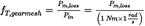
shall be added to receive the total torque dependent loss coefficient fT for the transmission system:
fT = fT,gearmesh + fT,bear
where:
=
Total torque dependent loss coefficient for the transmission system [-]
=
Torque dependent loss coefficient for the bearings [-]
=
Torque dependent loss coefficient for the gear meshes [-]
=
Fixed input power of the transmission; Pin = (1 Nm * 1 rad/s) [W]
3.1.1.14.The torque dependent losses on the input shaft for the specific gear shall be calculated by:U.K.
Tl,inT = fT * Tin
where:
=
Torque dependent loss related to input shaft [Nm]
=
Torque at the input shaft [Nm]
3.1.2.The torque independent losses shall be measured in accordance with the procedure described in the following.U.K.
3.1.2.1.General requirementsU.K.
The transmission used for the measurements shall be in accordance with the drawing specifications for series production transmissions and shall be new.
Modifications to the transmission to meet the testing requirements of this Annex, e.g. for the inclusion of measurement sensors or adaption of an external oil conditioning system are permitted.
The tolerance limits in this paragraph refer to measurement values without sensor uncertainty.
Total tested time per transmission individual and gear shall not exceed 2,5 times the actual testing time per gear (allowing re-testing of transmission if needed due to measuring or rig error).
The same transmission individual may be used for a maximum of 10 different tests, e.g. for tests of transmission torque losses for variants with and without retarder (with different temperature requirements) or with different oils. If the same transmission individual is used for tests of different oils, the recommended factory fill oil shall be tested first.
It is not permitted to run a certain test multiple times to choose a test series with the lowest results.
Upon request of the approval authority the applicant for a certificate shall specify and prove the conformity with the requirements defined in this Annex.
3.1.2.2.Differential measurementsU.K.
To subtract influences caused by the test rig setup (e.g. bearings, clutches) from the measured torque losses, differential measurements are permitted to determine these parasitic torques. The measurements shall be performed at the same speed steps and same test rig bearing temperature(s) ± 3 K used for the testing. The torque sensor measurement uncertainty shall be below 0,3 Nm.
3.1.2.3.Run-inU.K.
On request of the applicant a run-in procedure may be applied to the transmission. The following provisions shall apply for a run-in procedure.
3.1.2.3.1.The procedure shall not exceed 30 hours per gear and 100 hours in total.U.K.
3.1.2.3.2.The application of the input torque shall be limited to 100 % of maximum input torque.U.K.
3.1.2.3.3.The maximum input speed shall be limited by the specified maximum speed for the transmission.U.K.
3.1.2.3.4.The speed and torque profile for the run-in procedure shall be specified by the manufacturer.U.K.
3.1.2.3.5.The run-in procedure shall be documented by the manufacturer with regard to run-time, speed, torque and oil temperature and reported to the Approval authority.U.K.
3.1.2.3.6.The requirements for the ambient temperature (3.1.2.5.1.), measurement accuracy (3.1.4.), test set-up (3.1.8.) and installation angle (3.1.3.2) shall not apply for the run-in procedure.U.K.
3.1.2.4.Pre-conditioningU.K.
3.1.2.4.1.Pre-conditioning of the transmission and the test rig equipment to achieve correct and stable temperatures before the run-in and testing procedures is allowed.U.K.
3.1.2.4.2.The pre-conditioning shall be performed on the direct drive gear without applied torque to the output shaft. If the transmission is not equipped with a direct drive gear, the gear with the ratio closest to 1:1 shall be used.U.K.
3.1.2.4.3.The maximum input speed shall be limited by the specified maximum speed for the transmission.U.K.
3.1.2.4.4.The maximum combined time for the pre-conditioning shall not exceed 50 hours in total for one transmission. Since the complete testing of a transmission may be divided into multiple test sequences (e.g. each gear tested with a separate sequence), the pre-conditioning may be split into several sequences. Each of the single pre-conditioning sequences shall not exceed 60 minutes.U.K.
3.1.2.4.5.The pre-conditioning time shall not be accounted to the time span allocated for the run-in or test procedures.U.K.
3.1.2.5.Test conditionsU.K.
3.1.2.5.1.Ambient temperatureU.K.
The ambient temperature during the test shall be in a range of 25 °C ± 10 K.
The ambient temperature shall be measured 1 m laterally from the transmission.
The ambient temperature limit shall not apply for the run-in procedure.
3.1.2.5.2.Oil temperatureU.K.
Except for the oil, no external heating is allowed.
During measurement (except stabilization) the following temperature limits shall apply:
For SMT/AMT/DCT transmissions, the drain plug oil temperature shall not exceed 83 °C when measuring without retarder and 87 °C with retarder mounted to the transmission. If measurements of a transmission without retarder are to be combined with separate measurements of a retarder, the lower temperature limit shall apply to compensate for the retarder drive mechanism and step-up gear and for the clutch in case of a disengageable retarder.
For torque converter planetary transmissions and for transmissions having more than two friction clutches, the drain plug oil temperature shall not exceed 93 °C without retarder and 97 °C with retarder.
To apply the above defined increased temperature limits for testing with retarder, the retarder shall be integrated in the transmission or have an integrated cooling or oil system with the transmission.
During the run-in, the same oil temperature specifications as for regular testing shall apply.
Exceptional oil temperature peaks up to 110 °C are allowed for the following conditions:
during run-in procedure up to maximum of 10 % of the applied run-in time,
during stabilization time.
The oil temperature shall be measured at the drain plug or in the oil sump.
3.1.2.5.3.Oil qualityU.K.
New, recommended first fill oil for the European market shall be used in the test. The same oil fill may be used for run-in and torque measurement.
3.1.2.5.4.Oil viscosityU.K.
If multiple oils are recommended for first fill, they are considered to be equal if the oils have a kinematic viscosity within 10 % of each other at the same temperature (within the specified tolerance band for KV100). Any oil with lower viscosity than the oil used in the test shall be considered to result in lower losses for the tests performed within this option. Any additional first fill oil must fall either in the 10 % tolerance band or have lower viscosity than the oil in the test to be covered by the same certificate.
3.1.2.5.5.Oil level and conditioningU.K.
The oil level shall meet the nominal specifications for the transmission.
If an external oil conditioning system is used, the oil inside the transmission shall be kept to the specified volume that corresponds to the specified oil level.
To guarantee that the external oil conditioning system is not influencing the test, one test point shall be measured with the conditioning system both on and off. The deviation between the two measurements of the torque loss (= input torque) shall be less than 5 %. The test point is specified as follows:
gear = highest indirect gear,
input speed = 1 600 rpm,
temperatures as specified under 3.1.2.5.
For transmissions with hydraulic pressure control or a smart lubrication system, the measurement of torque independent losses shall be performed with two different settings: first with the transmission system pressure set to at least the minimum value for conditions with engaged gear and a second time with the maximum possible hydraulic pressure (see 3.1.6.3.1).
3.1.3.InstallationU.K.
3.1.3.1.The electric machine and the torque sensor shall be mounted to the input side of the transmission. The output shaft shall rotate freely.U.K.
3.1.3.2.The installation of the transmission shall be done with an angle of inclination as for installation in the vehicle according to the homologation drawing ± 1° or at 0° ± 1°.U.K.
3.1.3.3.The internal oil pump shall be included in the transmission.U.K.
3.1.3.4.If an oil cooler is either optional or required with the transmission, the oil cooler may be excluded in the test or any oil cooler may be used in the test.U.K.
3.1.3.5Transmission testing can be done with or without power take-off drive mechanism and/or power take-off. For establishing the power losses of power take-offs and /or power take-off drive mechanism, the values in Annex VII to this regulation are applied. These values assume that the transmission is tested without power take-off drive mechanism and /or power take-off.U.K.
3.1.3.6.Measuring the transmission may be performed with or without single dry clutch (with one or two plates) installed. Clutches of any other type shall be installed during the test.U.K.
3.1.3.7.The individual influence of parasitic loads shall be calculated for each specific test rig setup and torque sensor as described in 3.1.8.U.K.
3.1.4.Measurement equipmentU.K.
The calibration laboratory facilities shall comply with the requirements of either ISO/TS 16949, ISO 9000 series or ISO/IEC 17025. All laboratory reference measurement equipment, used for calibration and/or verification, shall be traceable to national (international) standards.
3.1.4.1.TorqueU.K.
The torque sensor measurement uncertainty shall be below 0,3 Nm.
The use of torque sensors with higher measurement uncertainties is allowed if the part of the uncertainty exceeding 0,3 Nm can be calculated and is added to the measured torque loss as described in 3.1.8. Measurement uncertainty.
3.1.4.2.SpeedU.K.
The uncertainty of the speed sensors shall not exceed ± 1 rpm.
3.1.4.3.TemperatureU.K.
The uncertainty of the temperature sensors for the measurement of the ambient temperature shall not exceed ± 1,5 K.
The uncertainty of the temperature sensors for the measurement of the oil temperature shall not exceed ± 1,5 K.
3.1.4.4.PressureU.K.
The uncertainty of the pressure sensors shall not exceed 1 % of the maximum measured pressure.
3.1.4.5.VoltageU.K.
The uncertainty of the voltmeter shall not exceed 1 % of the maximum measured voltage.
3.1.4.6.Electric currentU.K.
The uncertainty of the amperemeter shall not exceed 1 % of the maximum measured current.
3.1.5.Measurement signals and data recordingU.K.
At least the following signals shall be recorded during the measurement:
Input torques [Nm]
Input rotational speeds [rpm]
Ambient temperature [°C]
Oil temperature [°C]
If the transmission is equipped with a shift and/or clutch system that is controlled by hydraulic pressure or with a mechanically driven smart lubrication system, additionally to be recorded:
Oil pressure [kPa]
If the transmission is equipped with transmission electric auxiliary, additionally to be recorded:
Voltage of transmission electric auxiliary [V]
Current of transmission electric auxiliary [A]
For differential measurements for the compensation of influences caused by the test rig setup, additionally shall be recorded:
Test rig bearing temperature [°C]
The sampling and recording rate shall be 100 Hz or higher.
A low pass filter shall be applied to reduce measurement errors.
3.1.6.Test procedureU.K.
3.1.6.1.Zero torque signal compensation:U.K.
The zero-signal of the torque sensor(s) shall be measured. For the measurement the sensor(s) shall be installed in the test rig. The drivetrain of the test rig (input & output) shall be free of load. The measured signal deviation from zero shall be compensated.
3.1.6.2.Speed range:U.K.
The torque loss shall be measured for the following speed steps (speed of the input shaft): 600, 900, 1 200, 1 600, 2 000, 2 500, 3 000, […] rpm up to the maximum speed per gear according to the specifications of the transmission or the last speed step before the defined maximum speed.
The speed ramp (time for the change between two speed steps) shall not extend 20 seconds.
3.1.6.3.Measurement sequence:U.K.
If the transmission is equipped with smart lubrication systems and/or transmission electric auxiliaries, the measurement shall be conducted with two measurement settings of of these systems:
A first measurement sequence (3.1.6.3.2. to 3.1.6.3.4.) shall be performed with the lowest power consumption by hydraulical and electrical systems when operated in the vehicle (low loss level).
The second measurement sequence shall be performed with the systems set to work with the highest possible power consumption when operated in the vehicle (high loss level).
The measurements shall be performed beginning with the lowest up to the highest speed.
For each speed step a minimum of 5 seconds stabilization time within the temperature limits defined in 3.1.2.5 is required. If needed, the stabilization time may be extended by the manufacturer to maximum 60 seconds. Oil and ambient temperatures shall be recorded during the stabilization.
After the stabilization time, the measurement signals listed in 3.1.5. shall be recorded for the test point for 05-15 seconds.
Each measurement shall be performed two times per measurement setting.
3.1.7.Measurement validationU.K.
3.1.7.1.The arithmetic mean values of torque, speed, (if applicable) voltage and current for the 05-15 seconds measurement shall be calculated for each of the measurements.U.K.
3.1.7.2.The averaged speed deviation shall be below ± 5 rpm of the speed set point for each measured point for the complete torque loss series.U.K.
3.1.7.3.The mechanical torque losses and (if applicable) electrical power consumption shall be calculated for each of the measurements as followed:U.K.
Tloss = Tin
Pel = I * U
It is allowed to subtract influences caused by the test rig setup from the torque losses (3.1.2.2.).
3.1.7.4.The mechanical torque losses and (if applicable) electrical power consumption from the two sets shall be averaged (arithmetic mean values).U.K.
3.1.7.5.The deviation between the averaged torque losses of the two measurement points for each setting shall be below ± 5 % of the average or ± 1 Nm, whichever value is larger. Then, the arithmetic average of the two averaged power values shall be taken.U.K.
3.1.7.6.If the deviation is higher, the largest averaged torque loss value shall be taken or the test shall be repeated for the gear.U.K.
3.1.7.7.The deviation between the averaged electric power consumption (voltage * current) values of the two measurements for each measurement setting shall be below ± 10 % of the average or ± 5 W, whichever value is larger. Then, the arithmetic average of the two averaged power values shall be taken.U.K.
3.1.7.8.If the deviation is higher, the set of averaged voltage and current values giving the largest averaged power consumption shall be taken, or the test shall be repeated for the gear.U.K.
3.1.8.Measurement uncertaintyU.K.
The part of the calculated total uncertainty UT,loss exceeding 0,3 Nm shall be added to Tloss for the reported torque loss Tloss,rep . If UT,loss is smaller than 0,3 Nm, then Tloss,rep = Tloss .
Tloss,rep = Tloss + MAX (0, (UT,loss – 0,3 Nm))
The total uncertainty UT,loss of the torque loss shall be calculated based on the following parameters:
Temperature effect
Parasitic loads
Calibration error (incl. sensitivity tolerance, linearity, hysteresis and repeatability)
The total uncertainty of the torque loss (UT,loss ) is based on the uncertainties of the sensors at 95 % confidence level. The calculation shall be done as the square root of the sum of squares (‘Gaussian law of error propagation’).
wpara = senspara * ipara


where:
=
Measured torque loss (uncorrected) [Nm]
=
Reported torque loss (after uncertainty correction) [Nm]
=
Total expanded uncertainty of torque loss measurement at 95 % confidence level [Nm]
=
Uncertainty of input torque loss measurement [Nm]
=
Uncertainty by temperature influence on current torque signal [Nm]
=
Temperature influence on current torque signal per Kref, declared by sensor manufacturer [%]
=
Uncertainty by temperature influence on zero torque signal (related to nominal torque) [Nm]
=
Temperature influence on zero torque signal per Kref (related to nominal torque), declared by sensor manufacturer [%]
=
Reference temperature span for uTKC and uTK0, wtk0 and wtkc, declared by sensor manufacturer [K]
=
Difference in sensor temperature between calibration and measurement [K]. If the sensor temperature cannot be measured, a default value of ΔK = 15 K shall be used.
=
Current/measured torque value at torque sensor [Nm]
=
Nominal torque value of torque sensor [Nm]
=
Uncertainty by torque sensor calibration [Nm]
=
Relative calibration uncertainty (related to nominal torque) [%]
=
Calibration advancement factor (if declared by sensor manufacturer, otherwise = 1)
=
Uncertainty by parasitic loads [Nm]
=
senspara * ipara
Relative influence of forces and bending torques caused by misalignment
=
Maximum influence of parasitic loads for specific torque sensor declared by sensor manufacturer [%]; if no specific value for parasitic loads is declared by the sensor manufacturer, the value shall be set to 1,0 %
=
Maximum influence of parasitic loads for specific torque sensor depending on test setup (A/B/C, as defined below).
=
A) 10 % in case of bearings isolating the parasitic forces in front of and behind the sensor and a flexible coupling (or cardan shaft) installed functionally next to the sensor (downstream or upstream); furthermore, these bearings can be integrated in a driving/braking machine (e.g. electric machine) and/or in the transmission as long as the forces in the machine and/or transmission are isolated from the sensor. See figure 1.

=
B) 50 % in case of bearings isolating the parasitic forces in front of and behind the sensor and no flexible coupling installed functionally next to the sensor; furthermore, these bearings can be integrated in a driving/braking machine (e.g. electric machine) and/or in the transmission as long as the forces in the machine and/or transmission are isolated from the sensor. See figure 2.

=
C) 100 % for other setups
3.2.Option 2: Measurement of the torque independent losses, measurement of the torque loss at maximum torque and interpolation of the torque dependent losses based on a linear modelU.K.
Option 2 describes the determination of the torque loss by a combination of measurements and linear interpolation. Measurements shall be performed for the torque independent losses of the transmission and for one load point of the torque dependent losses (maximum input torque). Based on the torque losses at no load and at maximum input torque, the torque losses for the input torques in between shall be calculated with the torque loss coefficient fTlimo .
The torque loss Tl,in on the input shaft of the transmission shall be calculated by
Tl,in (nin , Tin , gear) = Tl,in,min_loss + fTlimo * Tin + T l,in,min_el + fel_corr * Tin
The torque loss coefficient based on the linear model fTlimo shall be calculated by

where:
=
Torque loss related to input shaft [Nm]
=
Drag torque loss at transmission input, measured with free rotating output shaft from testing without load [Nm]
=
Speed at the input shaft [rpm]
=
Torque loss coefficient based on linear model [-]
=
Torque at the input shaft [Nm]
=
Maximum tested torque at the input shaft (normally 100 % input torque, refer to 3.2.5.2. and 3.4.4.) [Nm]
=
Torque loss related to input shaft with Tin = Tin,maxT
=
Loss correction for electric power loss level depending on input torque [-]
=
Additional torque loss on input shaft by electric consumers [Nm]
=
Additional torque loss on input shaft by electric consumers corresponding to minimum electric power [Nm]
The correction factor for the torque dependent electric torque losses fel_corr and the torque loss at the input shaft of the transmission caused by the power consumption of transmission electric auxiliary Tl,in,el shall be calculated as described in paragraph 3.1.
3.2.1.The torque losses shall be measured in accordance with the procedure described in the following.U.K.
3.2.1.1.General requirements:U.K.
As specified for Option 1 in 3.1.2.1.
3.2.1.2.Differential measurements:U.K.
As specified for Option 1 in 3.1.2.2.
3.2.1.3.Run-inU.K.
As specified for Option 1 in 3.1.2.3.
3.2.1.4.Pre-conditioningU.K.
As specified for Option 3 in 3.3.2.1.
3.2.1.5.Test conditionsU.K.
3.2.1.5.1.Ambient temperatureU.K.
As specified for Option 1 in 3.1.2.5.1.
3.2.1.5.2.Oil temperatureU.K.
As specified for Option 1 in 3.1.2.5.2.
3.2.1.5.3.Oil quality / Oil viscosityU.K.
As specified for Option 1 in 3.1.2.5.3 and 3.1.2.5.4.
3.2.1.5.4.Oil level and conditioningU.K.
As specified for Option 3 in 3.3.3.4.
3.2.2.InstallationU.K.
As specified for Option 1 in 3.1.3. for the measurement of the torque independent losses.
As specified for Option 3 in 3.3.4. for the measurement of the torque dependent losses.
3.2.3.Measurement equipmentU.K.
As specified for Option 1 in 3.1.4. for the measurement of the torque independent losses.
As specified for Option 3 in 3.3.5. for the measurement of the torque dependent losses.
3.2.4.Measurement signals and data recordingU.K.
As specified for Option 1 in 3.1.5 for the measurement of the torque independent losses.
As specified for Option 3 in 3.3.7 for the measurement of the torque dependent losses.
3.2.5.Test procedureU.K.
The torque loss map to be applied to the simulation tool contains the torque loss values of a transmission depending on rotational input speed and input torque.
To determine the torque loss map for a transmission, the basic torque loss map data shall be measured and calculated as specified in this paragraph. The torque loss results shall be complemented in accordance with 3.4 and formatted in accordance with Appendix 12 for the further processing by the simulation tool.
3.2.5.1.The torque independent losses shall be determined by the procedure described in 3.1.1. for the torque independent losses for Option 1 only for the low loss level setting of electric and hydraulic consumers.U.K.
3.2.5.2.Determine the torque dependent losses for each of the gears using the procedure described for Option 3 in 3.3.6., diverging in the applicable torque range:U.K.
Torque range:
The torque losses for each gear shall be measured at 100 % of the maximum transmission input torque per gear.
In the case the output torque exceeds 10 kNm (for a theoretical loss free transmission) or the input power exceeds the specified maximum input power, point 3.4.4. shall apply.
3.2.6.Measurement validationU.K.
As specified for Option 3 in 3.3.8.
3.2.7.Measurement uncertaintyU.K.
As specified for Option 1 in 3.1.8. for the measurement of the torque independent losses.
As specified for Option 3 in 3.3.9. for the measurement of the torque dependent loss.
3.3.Option 3: Measurement of the total torque loss.U.K.
Option 3 describes the determination of the torque loss by full measurement of the torque dependent losses including the torque independent losses of the transmission.
3.3.1.General requirementsU.K.
As specified for Option 1 in 3.1.2.1.
3.3.1.1Differential measurements:U.K.
As specified for Option 1 in 3.1.2.2.
3.3.2.Run-inU.K.
As specified for Option 1 in 3.1.2.3.
3.3.2.1Pre-conditioningU.K.
As specified for Option 1 in 3.1.2.4. with an exception for the following:
The pre-conditioning shall be performed on the direct drive gear without applied torque to the output shaft or target torque on the output shaft set to zero. If the transmission is not equipped with a direct drive gear, the gear with the ratio closest to 1:1 shall be used.
or
The requirements as specified in 3.1.2.4. shall apply, with an exception for the following:
The pre-conditioning shall be performed on the direct drive gear without applied torque to the output shaft or the torque on the output shaft being within +/- 50 Nm. If the transmission is not equipped with a direct drive gear, the gear with the ratio closest to 1:1 shall be used.
or, if the test rig includes a (master friction) clutch at the input shaft:
The requirements as specified in 3.1.2.4. shall apply, with an exception for the following:
The pre-conditioning shall be performed on the direct drive gear without applied torque to the output shaft or without applied torque to the input shaft. If the transmission is not equipped with a direct drive gear, the gear with the ratio closest to 1:1 shall be used.
The transmission would then be driven from the output side. Those proposals could also be combined.
3.3.3.Test conditionsU.K.
3.3.3.1.Ambient temperatureU.K.
As specified for Option 1 in 3.1.2.5.1.
3.3.3.2.Oil temperatureU.K.
As specified for Option 1 in 3.1.2.5.2.
3.3.3.3.Oil quality / Oil viscosityU.K.
As specified for Option 1 in 3.1.2.5.3 and 3.1.2.5.4.
3.3.3.4.Oil level and conditioningU.K.
The requirements as specified in 3.1.2.5.5. shall apply, diverging in the following:
The test point for the external oil conditioning system is specified as follows:
highest indirect gear,
input speed = 1 600 rpm,
input torque = maximum input torque for the highest indirect gear
3.3.4.InstallationU.K.
The test rig shall be driven by electric machines (input and output).
Torque sensors shall be installed at the input and output side of the transmission.
Other requirements as specified in 3.1.3. shall apply.
3.3.5.Measurement equipmentU.K.
For the measurement of the torque independent losses, the measurement equipment requirements as specified for Option 1 in 3.1.4. shall apply.
For the measurement of the torque dependent losses, the following requirements shall apply:
The torque sensor measurement uncertainty shall be below 5 % of the measured torque loss or 1 Nm (whichever value is larger).
The use of torque sensors with higher measurement uncertainties is allowed if the parts of the uncertainty exceeding 5 % or 1 Nm can be calculated and the smaller of those parts is added to the measured torque loss.
The torque measurement uncertainty shall be calculated and included as described under 3.3.9.
Other measurement equipment requirements as specified for Option 1 in 3.1.4. shall apply.
3.3.6.Test procedureU.K.
3.3.6.1.Zero torque signal compensation:U.K.
As specified in 3.1.6.1.
3.3.6.2.Speed rangeU.K.
The torque loss shall be measured for the following speed steps (speed of the input shaft): 600, 900, 1 200, 1 600, 2 000, 2 500, 3 000, […] rpm up to the maximum speed per gear according to the specifications of the transmission or the last speed step before the defined maximum speed.
The speed ramp (time for the change between two speed steps) shall not exceed 20 seconds.
3.3.6.3.Torque rangeU.K.
For each speed step the torque loss shall be measured for the following input torques: 0 (free rotating output shaft), 200, 400, 600, 900, 1 200, 1 600, 2 000, 2 500, 3 000, 3 500, 4 000, […] Nm up to the maximum input torque per gear according to the specifications of the transmission or the last torque step before the defined maximum torque and/or the last torque step before the output torque of 10 kNm.
In the case the output torque exceeds 10 kNm (for a theoretical loss free transmission) or the input power exceeds the specified maximum input power, point 3.4.4. shall apply.
The torque ramp (time for the change between two torque steps) shall not exceed 15 seconds (180 seconds for option 2).
To cover the complete torque range of a transmission in the above defined map, different torque sensors with limited measurement ranges may be used on the input/output side. Therefore the measurement may be divided into sections using the same set of torque sensors. The overall torque loss map shall be composed of these measurement sections.
3.3.6.4.Measurement sequenceU.K.
3.3.6.4.1.The measurements shall be performed beginning with the lowest up to the highest speed.U.K.
3.3.6.4.2.The input torque shall be varied according to the above defined torque steps from the lowest to the highest torque which is covered by the current torque sensors for each speed step.U.K.
3.3.6.4.3.For each speed and torque step a minimum of 5 seconds stabilization time within the temperature limits defined in 3.3.3. is required. If needed, the stabilization time may be extended by the manufacturer to maximum 60 seconds (maximum 180 seconds for option 2). Oil and ambient temperatures shall be recorded during the stabilization.U.K.
3.3.6.4.4.The measurement set shall be performed two times in total. For that purpose, sequenced repetition of sections using the same set of torque sensors is allowed.U.K.
3.3.7.Measurement signals and data recordingU.K.
At least the following signals shall be recorded during the measurement:
Input and output torques [Nm]
Input and output rotational speeds [rpm]
Ambient temperature [°C]
Oil temperature [°C]
If the transmission is equipped with a shift and/or clutch system that is controlled by hydraulic pressure or with a mechanically driven smart lubrication system, additionally to be recorded:
Oil pressure [kPa]
If the transmission is equipped with transmission electric auxiliary, additionally to be recorded:
Voltage of transmission electric auxiliary [V]
Current of transmission electric auxiliary [A]
For differential measurements for compensation of influences by test rig setup, additionally to be recorded:
Test rig bearing temperature [°C]
The sampling and recording rate shall be 100 Hz or higher.
A low pass filter shall be applied to avoid measurement errors.
3.3.8.Measurement validationU.K.
3.3.8.1.The arithmetic mean values of torque, speed, if applicable voltage and current for the 05-15 seconds measurement shall be calculated for each of the two measurements.U.K.
3.3.8.2.The measured and averaged speed at the input shaft shall be below ± 5 rpm of the speed set point for each measured operating point for the complete torque loss series. The measured and averaged torque at the input shaft shall be below ± 5 Nm or ± 5 % of the torque set point whichever value is larger for each measured operating point for the complete torque loss series.U.K.
3.3.8.3.The mechanical torque losses and (if applicable) electrical power consumption shall be calculated for each of the measurements as followed:U.K.
Pel = I * U

It is allowed to subtract influences caused by the test rig setup from the torque losses (3.3.2.2.).
3.3.8.4.The mechanical torque losses and (if applicable) electrical power consumption from the two sets shall be averaged (arithmetic mean values).U.K.
3.3.8.5.The deviation between the averaged torque losses of the two measurement sets shall be below ± 5 % of the average or ± 1 Nm (whichever value is larger). The arithmetic average of the two averaged torque loss values shall be taken. If the deviation is higher, the largest averaged torque loss value shall be taken or the test shall be repeated for the gear.U.K.
3.3.8.6.The deviation between the averaged electric power consumption (voltage*current) values of the two measurement sets shall be below ± 10 % of the average or ± 5 W, whichever value is larger. Then, the arithmetic average of the two averaged power values shall be taken.U.K.
3.3.8.7.If the deviation is higher, the set of averaged voltage and current values giving the largest averaged power consumption shall be taken, or the test shall be repeated for the gear.U.K.
3.3.9.Measurement uncertaintyU.K.
The part of the calculated total uncertainty UT,loss exceeding 5 % of Tloss or 1 Nm (ΔUT,loss ), whichever value of ΔUT,loss is smaller, shall be added to Tloss for the reported torque loss Tloss,rep . If UT,loss is smaller than 5 % of Tloss or 1 Nm, then Tloss,rep = Tloss .
Tloss,rep = Tloss + MAX (0, ΔUT,loss )
ΔUT,loss = MIN ((UT,loss – 5 % * Tloss ), (UT,loss – 1 Nm))
For each measurement set, the total uncertainty UT,loss of the torque loss shall be calculated based on the following parameters:
Temperature effect
Parasitic loads
Calibration error (incl. sensitivity tolerance, linearity, hysteresis and repeatability)
The total uncertainty of the torque loss (UT,loss ) is based on the uncertainties of the sensors at 95 % confidence level. The calculation shall be done as the square root of the sum of squares (‘Gaussian law of error propagation’).
wpara = senspara * ipara


where:
=
Measured torque loss (uncorrected) [Nm]
=
Reported torque loss (after uncertainty correction) [Nm]
=
Total expanded uncertainty of torque loss measurement at 95 % confidence level [Nm]
=
Uncertainty of input/output torque loss measurement separately for input and output torque sensor[Nm]
=
Gear ratio [-]
=
Uncertainty by temperature influence on current torque signal [Nm]
=
Temperature influence on current torque signal per Kref, declared by sensor manufacturer [%]
=
Uncertainty by temperature influence on zero torque signal (related to nominal torque) [Nm]
=
Temperature influence on zero torque signal per Kref (related to nominal torque), declared by sensor manufacturer [%]
=
Reference temperature span for uTKC and uTK0, wtk0 and wtkc, declared by sensor manufacturer [K]
=
Difference in sensor temperature between calibration and measurement [K]. If the sensor temperature cannot be measured, a default value of ΔK = 15 K shall be used.
=
Current/measured torque value at torque sensor [Nm]
=
Nominal torque value of torque sensor [Nm]
=
Uncertainty by torque sensor calibration [Nm]
=
Relative calibration uncertainty (related to nominal torque) [%]
=
calibration advancement factor (if declared by sensor manufacturer, otherwise = 1)
=
Uncertainty by parasitic loads [Nm]
=
senspara * ipara
Relative influence of forces and bending torques caused by misalignment [%]
=
Maximum influence of parasitic loads for specific torque sensor declared by sensor manufacturer [%]; if no specific value for parasitic loads is declared by the sensor manufacturer, the value shall be set to 1,0 %
=
Maximum influence of parasitic loads for specific torque sensor depending on test setup (A/B/C, as defined below).
=
A) 10 % in case of bearings isolating the parasitic forces in front of and behind the sensor and a flexible coupling (or cardan shaft) installed functionally next to the sensor (downstream or upstream); furthermore, these bearings can be integrated in a driving/braking machine (e.g. electric machine) and/or in the transmission as long as the forces in the machine and/or transmission are isolated from the sensor. See figure 3.

=
B) 50 % in case of bearings isolating the parasitic forces in front of and behind the sensor and no flexible coupling installed functionally next to the sensor; furthermore, these bearings can be integrated in a driving/braking machine (e.g. electric machine) and/or in the transmission as long as the forces in the machine and/or transmission are isolated from the sensor. See figure 4.

=
C) 100 % for other setups
3.4.Complement of input files for the simulation toolU.K.
For each gear a torque loss map covering the defined input speed and input torque steps shall be determined with one of the specified testing options or standard torque loss values. For the input file for the simulation tool, this basic torque loss map shall be complemented as described in the following:
3.4.1.In the cases the highest tested input speed was the last speed step below the defined maximum permissible transmission speed, an extrapolation of the torque loss shall be applied up to the maximum speed with linear regression based on the two last measured speed steps.U.K.
3.4.2.In the cases the highest tested input torque was the last torque step below the defined maximum permissible transmission torque, an extrapolation of the torque loss shall be applied up to the maximum torque with linear regression based on the two last measured torque steps for the corresponding speed step. In order to handle engine torque tolerances, etc., the simulation tool will, if required, perform an extrapolation of the torque loss for input torques up to 10 % above said defined maximum permissible transmission torque.U.K.
3.4.3.In the case of extrapolation of the torque loss values for maximum input speed and maximum input torque at the same time, the torque loss for the combined point of highest speed and highest torque shall be calculated with two-dimensional linear extrapolation.U.K.
3.4.4.If the maximum output torque exceeds 10 kNm (for a theoretical loss free transmission), and/or for all speed and torque points with input power higher than the specified maximum input power, the manufacturer may choose to take the torque loss values for all torques higher than 10 kNm, and/or for all speed and torque points with input power higher than the specified maximum input power, respectively, from one of:U.K.
Calculated fallback values (Appendix 8)
Option 1
Option 2 or 3 in combination with a torque sensor for higher output torques (if required)
For cases (i) and (ii) in Option 2, the torque losses at load shall be measured at the input torque that corresponds to output torque 10 kNm and/or the specified maximum input power.
3.4.5.For speeds below the defined minimum speed and the additional input speed step of 0 rpm, the reported torque losses determined for the minimum speed step shall be copied.U.K.
3.4.6.To cover the range of negative input torques during vehicle coasting conditions, the torque loss values for positive input torques shall be copied for the related negative input torques.U.K.
3.4.7.Upon agreement of an approval authority, the torque losses for the input speeds below 1 000 rpm may be replaced by the torque losses at 1 000 rpm when the measurement is technically not possible.U.K.
3.4.8.If the measurement of speed points is technically not possible (e.g. due to natural frequency), the manufacturer may, in agreement with the approval authority, calculate the torque losses by interpolation or extrapolation (limited to max. 1 speed step per gear).U.K.
3.4.9.The torque loss map data shall be formatted and saved as specified in Appendix 12 to this Annex.U.K.
4.Torque converter (TC)U.K.
The torque converter characteristics to be determined for the simulation tool input consist of Tpum 1000 (the reference torque at 1 000 rpm input speed) and μ (the torque ratio of the torque converter). Both are depending on the speed ratio v (= output (turbine) speed / input (pump) speed for the torque converter) of the torque converter.
For determination of the characteristics of the TC, the applicant for a certificate shall apply the following method, irrespective of the chosen option for the assessment of the transmission torque losses.
To take the two possible arrangements of the TC and the mechanical transmission parts into account, the following differentiation between case S and P shall apply:
:
TC and mechanical transmission parts in serial arrangement
:
TC and mechanical transmission parts in parallel arrangement (power split installation)
For case S arrangements the TC characteristics may be evaluated either separate from the mechanical transmission or in combination with the mechanical transmission. For case P arrangements the evaluation of TC characteristic is only possible in combination with the mechanical transmission. However, in this case and for the hydromechanical gears subject to measurement the whole arrangement, torque converter and mechanical transmission, is considered as a TC with similar characteristic curves as a sole torque converter.
For the determination of the torque converter characteristics two measurement options may be applied:
Option A: measurement at constant input speed
Option B: measurement at constant input torque according to SAE J643
The manufacturer may choose option A or B for case S and case P arrangements.
For the input to the simulation tool, the torque ratio μ and reference torque Tpum of the torque converter shall be measured for a range of v ≤ 0,95 (= vehicle propulsion mode). The range of v ≥ 1,00 (= vehicle coasting mode) may either be measured or covered by using the standard values of Table 1.
In case of measurements together with a mechanical transmission the overrun point may be different from v = 1,00 and therefor the range of measured speed ratios shall be adjusted accordingly.
In case of use of standard values the data on torque converter characteristics provided to the simulation tool shall only cover the range of v ≤ 0,95 (or the adjusted speed ratio). The simulation tool automatically adds the standard values for overrun conditions.
Table 1
Default values for v ≥ 1,00
| v | μ | Tpum 1000 |
|---|---|---|
| 1,000 | 1,0000 | 0,00 |
| 1,100 | 0,9999 | – 40,34 |
| 1,222 | 0,9998 | – 80,34 |
| 1,375 | 0,9997 | – 136,11 |
| 1,571 | 0,9996 | – 216,52 |
| 1,833 | 0,9995 | – 335,19 |
| 2,200 | 0,9994 | – 528,77 |
| 2,500 | 0,9993 | – 721,00 |
| 3,000 | 0,9992 | – 1 122,0 |
| 3,500 | 0,9991 | – 1 648,0 |
| 4,000 | 0,9990 | – 2 326,0 |
| 4,500 | 0,9989 | – 3 182,0 |
| 5,000 | 0,9988 | – 4 242,0 |
4.1.Option A: Measured torque converter characteristics at constant speedU.K.
4.1.1.General requirementsU.K.
The torque converter used for the measurements shall be in accordance with the drawing specifications for series production torque converters.
Modifications to the TC to meet the testing requirements of this Annex, e.g. for the inclusion of measurement sensors are permitted.
Upon request of the approval authority the applicant for a certificate shall specify and prove the conformity with the requirements defined in this Annex.
4.1.2.Oil temperatureU.K.
The input oil temperature to the TC shall meet the following requirements:
The oil temperature for measurements of the TC separate from the transmission shall be 90 °C + 7/– 3 K.
The oil temperature for measurements of the TC together with the transmission (case S and case P) shall be 90 °C + 20/– 3 K.
The oil temperature shall be measured at the drain plug or in the oil sump.
In case the TC characteristics are measured separately form the transmission, the oil temperature shall be measured prior to entering the converter test drum/bench.
4.1.3.Oil flow rate and pressureU.K.
The input TC oil flow rate and output oil pressure of the TC shall be kept within the specified operational limits for the torque converter, depending on the related transmission type and the tested maximum input speed.
4.1.4.Oil quality/Oil viscosityU.K.
As specified for transmission testing in 3.1.2.5.3 and 3.1.2.5.4.
4.1.5.InstallationU.K.
The torque converter shall be installed on a testbed with a torque sensor, speed sensor and an electric machine installed at the input and output shaft of the TC.
4.1.6.Measurement equipmentU.K.
The calibration laboratory facilities shall comply with the requirements of either ISO/TS 16949, ISO 9000 series or ISO/IEC 17025. All laboratory reference measurement equipment, used for calibration and/or verification, shall be traceable to national (international) standards.
4.1.6.1.TorqueU.K.
The torque sensor measurement uncertainty shall be below 1 % of the measured torque value.
The use of torque sensors with higher measurement uncertainties is allowed if the part of the uncertainty exceeding 1 % of the measured torque can be calculated and is added to the measured torque loss as described in 4.1.7.
4.1.6.2.SpeedU.K.
The uncertainty of the speed sensors shall not exceed ± 1 rpm.
4.1.6.3.TemperatureU.K.
The uncertainty of the temperature sensors for the measurement of the ambient temperature shall not exceed ± 1,5 K.
The uncertainty of the temperature sensors for the measurement of the oil temperature shall not exceed ± 1,5 K.
4.1.7.Test procedureU.K.
4.1.7.1.Zero torque signal compensationU.K.
As specified in 3.1.6.1.
4.1.7.2.Measurement sequenceU.K.
4.1.7.2.1.The input speed npum of the TC shall be fixed to a constant speed within the range of:U.K.
1 000 rpm ≤ npum ≤ 2 000 rpm
4.1.7.2.2.The speed ratio v shall be adjusted by increasing the output speed ntur from 0 rpm up to the set value of npum .U.K.
4.1.7.2.3.The step width shall be 0,1 for the speed ratio range of 0 to 0,6 and 0,05 for the range of 0,6 to 0,95.U.K.
4.1.7.2.4.The upper limit of the speed ratio may be limited to a value below 0,95 by the manufacturer. In this case at least seven evenly distributed points between v = 0 and a value of v < 0,95 have to be covered by the measurement.U.K.
4.1.7.2.5.For each step a minimum of 3 seconds stabilization time within the temperature limits defined in 4.1.2. is required. If needed, the stabilization time may be extended by the manufacturer to maximum 60 seconds. The oil temperature shall be recorded during the stabilization.U.K.
4.1.7.2.6.For each step the signals specified in 4.1.8. shall be recorded for the test point for 3-15 seconds.U.K.
4.1.7.2.7.The measurement sequence (4.1.7.2.1. to 4.1.7.2.6.) shall be performed two times in total.U.K.
4.1.8.Measurement signals and data recordingU.K.
At least the following signals shall be recorded during the measurement:
Input (pump) torque Tc,pum [Nm]
Output (turbine) torque Tc,tur [Nm]
Input rotational (pump) speed npum [rpm]
Output rotational (turbine) speed ntur [rpm]
TC input oil temperature KTCin [°C]
The sampling and recording rate shall be 100 Hz or higher.
A low pass filter shall be applied to avoid measurement errors.
4.1.9.Measurement validationU.K.
4.1.9.1.The arithmetic mean values of torque and speed for the 03-15 seconds measurement shall be calculated for each of the two measurements.U.K.
4.1.9.2.The measured torques and speeds from the two sets shall be averaged (arithmetic mean values).U.K.
4.1.9.3.The deviation between the averaged torque of the two measurement sets shall be below ± 5 % of the average or ± 1 Nm (whichever value is larger). The arithmetic average of the two averaged torque values shall be taken. If the deviation is higher, the following value shall be taken for point 4.1.10. and 4.1.11. or the test shall be repeated for the TC.U.K.
for the calculation of ΔUT,pum/tur: smallest averaged torque value for Tc,pum/tur
for the calculation of torque ratio μ: largest averaged torque value for Tc,pum
for the calculation of torque ratio μ: smallest averaged torque value for Tc,tur
for the calculation of reference torque Tpum1000: smallest averaged torque value for Tc,pum
4.1.9.4.The measured and averaged speed and torque at the input shaft shall be below ± 5 rpm and ± 5 Nm of the speed and torque set point for each measured operating point for the complete speed ratio series.U.K.
4.1.10.Measurement uncertaintyU.K.
The part of the calculated measurement uncertainty UT,pum/tur exceeding 1 % of the measured torque Tc,pum/tur shall be used to correct the characteristic value of the TC as defined below.
ΔUT,pum/tur = MAX (0, (UT,pum/tur – 0,01 * Tc,pum/tur))
The uncertainty UT,pum/tur of the torque measurement shall be calculated based on the following parameter:
Calibration error (incl. sensitivity tolerance, linearity, hysteresis and repeatability)
The uncertainty UT,pum/tur of the torque measurement is based on the uncertainties of the sensors at 95 % confidence level.
UT,pum/tur = 2 * ucal

where:
=
Current / measured torque value at input/output torque sensor (uncorrected) [Nm]
=
Input (pump) torque (after uncertainty correction) [Nm]
=
Uncertainty of input / output torque measurement at 95 % confidence level separately for input and output torque sensor[Nm]
=
Nominal torque value of torque sensor [Nm]
=
Uncertainty by torque sensor calibration [Nm]
=
Relative calibration uncertainty (related to nominal torque) [%]
=
Calibration advancement factor (if declared by sensor manufacturer, otherwise = 1)
4.1.11.Calculation of TC characteristicsU.K.
For each measurement point, the following calculations shall be applied to the measurement data:
The torque ratio of the TC shall be calculated by
The speed ratio of the TC shall be calculated by
The reference torque at 1 000 rpm shall be calculated by


where:
=
Torque ratio of the TC [-]
=
Speed ratio of the TC [-]
=
Input (pump) torque (corrected) [Nm]
=
Input rotational (pump) speed [rpm]
=
Output rotational (turbine) speed [rpm]
=
Reference torque at 1 000 rpm [Nm]
4.2.Option B: Measurement at constant input torque (in accordance with SAE J643)U.K.
4.2.1.General requirementsU.K.
As specified in 4.1.1.
4.2.2.Oil temperatureU.K.
As specified in 4.1.2.
4.2.3.Oil flow rate and pressureU.K.
As specified in 4.1.3.
4.2.4.Oil qualityU.K.
As specified in 4.1.4.
4.2.5.InstallationU.K.
As specified in 4.1.5.
4.2.6.Measurement equipmentU.K.
As specified in 4.1.6.
4.2.7.Test procedureU.K.
4.2.7.1.Zero torque signal compensationU.K.
As specified in 3.1.6.1.
4.1.7.2.Measurement sequenceU.K.
4.2.7.2.1.The input torque Tpum shall be set to a positive level at npum = 1 000 rpm with the output shaft of the TC held non-rotating (output speed ntur = 0 rpm).U.K.
4.2.7.2.2.The speed ratio v shall be adjusted by increasing the output speed ntur from 0 rpm up to a value of ntur covering the usable range of v with at least seven evenly distributed speed points.U.K.
4.2.7.2.3.The step width shall be 0.1 for the speed ratio range of 0 to 0,6 and 0,05 for the range of 0,6 to 0,95.U.K.
4.2.7.2.4.The upper limit of the speed ratio may be limited to a value below 0,95 by the manufacturer.U.K.
4.2.7.2.5.For each step a minimum of 5 seconds stabilization time within the temperature limits defined in 4.2.2. is required. If needed, the stabilization time may be extended by the manufacturer to maximum 60 seconds. The oil temperature shall be recorded during the stabilization.U.K.
4.2.7.2.6.For each step the values specified in 4.2.8. shall be shall be recorded for the test point for 05-15 seconds.U.K.
4.2.7.2.7.The measurement sequence (4.2.7.2.1. to 4.2.7.2.6.) shall be performed two times in total.U.K.
4.2.8.Measurement signals and data recordingU.K.
As specified in 4.1.8.
4.2.9.Measurement validationU.K.
As specified in 4.1.9.
4.2.10.Measurement uncertaintyU.K.
As specified in 4.1.9.
4.2.11.Calculation of TC characteristicsU.K.
As specified in 4.1.11.
5.Other torque transferring components (OTTC)U.K.
The scope of this section includes engine retarders, transmission retarders, driveline retarders, and components that are treated in the simulation tool as a retarder. These components include vehicle starting devices like a single wet transmission input clutch or hydro-dynamic clutch.
5.1.Methods for establishing retarder drag lossesU.K.
The retarder drag torque loss is a function of the retarder rotor speed. Since the retarder can be integrated in different parts of the vehicle driveline, the retarder rotor speed depends on the drive part (= speed reference) and step-up ratio between drive part and retarder rotor as shown in Table 2.
Table 2
Retarder rotor speeds
where:
=
step-up ratio = retarder rotor speed/drive part speed
=
transmission ratio = transmission input speed/transmission output speed
Retarder configurations that are integrated in the engine and cannot be separated from the engine shall be tested in combination with the engine. This section does not cover these non-separable engine integrated retarders.
Retarders that can be disconnected from the driveline or the engine by any kind of clutch are considered to have zero rotor speed in disconnected condition and therefore have no power losses.
The retarder drag losses shall be measured with one of the following two methods:
Measurement on the retarder as a stand-alone unit
Measurement in combination with the transmission
5.1.1.General requirementsU.K.
In case the losses are measured on the retarder as stand-alone unit, the results are affected by the torque losses in the bearings of the test setup. It is permitted to measure these bearing losses and subtract them from the retarder drag loss measurements.
The manufacturer shall guarantee that the retarder used for the measurements is in accordance with the drawing specifications for series production retarders.
Modifications to the retarder to meet the testing requirements of this Annex, e.g. for the inclusion of measurement sensors or the adaption of an external oil conditioning systems are permitted.
Based on the family described in Appendix 6 to this Annex, measured drag losses for transmissions with retarder can be used for the same (equivalent) transmission without retarder.
The use of the same transmission unit for measuring the torque losses of variants with and without retarder is permitted.
Upon request of the approval authority the applicant for a certificate shall specify and prove the conformity with the requirements defined in this Annex.
5.1.2.Run-inU.K.
On request of the applicant a run-in procedure may be applied to the retarder. The following provisions shall apply for a run-in procedure.
5.1.2.1If the manufacturer applies a run-in procedure to the retarder, the run-in time for the retarder shall not exceed 100 hours at zero retarder apply torque. Optionally a share of a maximum of 6 hours with retarder apply torque may be included.U.K.
5.1.3.Test conditionsU.K.
5.1.3.1.Ambient temperatureU.K.
The ambient temperature during the test shall be in a range of 25 °C ± 10 K.
The ambient temperature shall be measured 1 m laterally from the retarder.
5.1.3.2.Ambient pressureU.K.
For magnetic retarders the minimum ambient pressure shall be 899 hPa according to International Standard Atmosphere (ISA) ISO 2533.
5.1.3.3.Oil or water temperatureU.K.
For hydrodynamic retarders:
Except for the fluid, no external heating is allowed.
In case of testing as stand-alone unit, the retarder fluid temperature (oil or water) shall not exceed 87 °C.
In case of testing in combination with transmission, the oil temperature limits for transmission testing shall apply.
5.1.3.4.Oil or water qualityU.K.
New, recommended first fill oil for the European market shall be used in the test.
For water retarders the water quality shall meet the specifications set out by the manufacturer for the retarder. The water pressure shall be set to a fixed value close to vehicle condition (1 ± 0,2 bar relative pressure at retarder input hose).
5.1.3.5.Oil viscosityU.K.
If several oils are recommended for first fill, they are considered to be equal if the oils have a kinematic viscosity within 50 % of each other at the same temperature (within the specified tolerance band for KV100).
5.1.3.6.Oil or water levelU.K.
The oil/water level shall meet the nominal specifications for the retarder.
5.1.4.InstallationU.K.
The electric machine, the torque sensor, and speed sensor shall be mounted at the input side of the retarder or transmission.
The installation of the retarder (and transmission) shall be done with an inclination angle as for installation in the vehicle according to the homologation drawing ± 1° or at 0° ± 1°.
5.1.5.Measurement equipmentU.K.
As specified for transmission testing in 3.1.4.
5.1.6.Test procedureU.K.
5.1.6.1.Zero torque signal compensation:U.K.
As specified for transmission testing in 3.1.6.1.
5.1.6.2.Measurement sequenceU.K.
The torque loss measurement sequence for the retarder testing shall follow the provisions for the transmission testing defined in 3.1.6.3.2. to 3.1.6.3.5.
5.1.6.2.1.Measurement on the retarder as stand-alone unitU.K.
When the retarder is tested as stand-alone unit, torque loss measurements shall be conducted using the following speed points:
200, 400, 600, 900, 1 200, 1 600, 2 000, 2 500, 3 000, 3 500, 4 000, 4 500, 5 000, continued up to the maximum retarder rotor speed.
5.1.6.2.2.Measurement in combination with the transmissionU.K.
5.1.6.2.2.1.In case the retarder is tested in combination with a transmission, the selected transmission gear shall allow the retarder to operate at its maximum rotor speed.U.K.
5.1.6.2.2.The torque loss shall be measured at the operating speeds as indicated for the related transmission testing.U.K.
5.1.6.2.2.3.Measurement points may be added for transmission input speeds below 600 rpm if requested by the manufacturer.U.K.
5.1.6.2.2.4.The manufacturer may separate the retarder losses from the total transmission losses by testing in the order as described below:U.K.
The load-independent torque loss for the complete transmission including retarder shall be measured as defined in point 3.1.2. for transmission testing in one of the higher transmission gears
= Tl,in,withret
The retarder and related parts shall be replaced with parts required for the equivalent transmission variant without retarder. The measurement of point (1) shall be repeated.
= Tl,in,withoutret
The load-independent torque loss for the retarder system shall be determined by calculating the differences between the two test data sets
= Tl,in,retsys = Tl,in,withret – Tl,in,withoutret
5.1.7.Measurement signals and data recordingU.K.
As specified for transmission testing in 3.1.5.
5.1.8.Measurement validationU.K.
All recorded data shall be checked and processed as defined for transmission testing in 3.1.7.
5.2.Complement of input files for the simulation toolU.K.
5.2.1Retarder torque losses for speeds below the lowest measurement speed shall be set equal to the measured torque loss at this lowest measurement speed.U.K.
5.2.2In case the retarder losses were separated out from the total losses by calculating the difference in data sets of testing with and without a retarder (see 5.1.6.2.2.4.), the actual retarder rotor speeds depend on the retarder location, and/or selected gear ratio and retarder step-up ratio and thereby may differ from the measured transmission input shaft speeds. The actual retarder rotor speeds relative to the measured drag loss data shall be calculated as described in 5.1. Table 2.U.K.
5.2.3The torque loss map data shall be formatted and saved as specified in Appendix 12 to this Annex.U.K.
6.Additional driveline components (ADC) / angle driveU.K.
6.1.Methods for establishing angle drive lossesU.K.
The angle drive losses shall be determined using one of the following cases:
6.1.1.Case A: Measurement on a separate angle driveU.K.
For the torque loss measurement of a separate angle drive, the three options as defined for the determination of the transmission losses shall apply:
:
Measured torque independent losses and calculated torque dependent losses (Transmission test option 1)
:
Measured torque independent losses and measured torque dependent losses at full load (Transmission test option 2)
:
Measurement under full load points (Transmission test option 3)
The measurement of the angle drive losses shall follow the procedure described for the related transmission test option in paragraph 3 diverging in the following requirements:
6.1.1.1Applicable speed range:U.K.
From 200 rpm (at the shaft to which the angle drive is connected) up to the maximum speed according to specifications of the angle drive or the last speed step before the defined maximum speed.
6.1.1.2Speed step size: 200 rpmU.K.
6.1.2.Case B: Individual measurement of an angle drive connected to a transmissionU.K.
In case the angle drive is tested in combination with a transmission, the testing shall follow one of the defined options for transmission testing:
:
Measured torque independent losses and calculated torque dependent losses (Transmission test option 1)
:
Measured torque independent losses and measured torque dependent losses at full load (Transmission test option 2)
:
Measurement under full load points (Transmission test option 3)
6.1.2.1The manufacturer may separate the angle drive losses from the total transmission losses by testing in the order as described below:U.K.
The torque loss for the complete transmission including angle drive shall be measured as defined for the applicable transmission testing option
= Tl,in,withad
The angle drive and related parts shall be replaced with parts required for the equivalent transmission variant without angle drive. The measurement of point (1) shall be repeated.
= Tl,in,withoutad
The torque loss for the angle drive system shall be determined by calculating the differences between the two test data sets
= Tl,in,adsys = Tl,in,withad – Tl,in,withoutad
6.2.Complement of input files for the simulation toolU.K.
6.2.1.Torque losses for speeds below the above defined minimum speed shall be set equal to the torque loss at the minimum speed.U.K.
6.2.2.In the cases the highest tested angle drive input speed was the last speed step below the defined maximum permissible angle drive speed, an extrapolation of the torque loss shall be applied up to the maximum speed with linear regression based on the two last measured speed steps.U.K.
6.2.3.To calculate the torque loss data for the input shaft of the transmission the angle drive is to be combined with, linear interpolation and extrapolation shall be used.U.K.
7.Conformity of the certified CO2 emissions and fuel consumption related propertiesU.K.
7.1.Every transmission, torque converter (TC), other torque transferring components (OTTC) and additional driveline components (ADC) shall be so manufactured as to conform to the approved type with regard to the description as given in the certificate and its annexes. The conformity of the certified CO2 emissions and fuel consumption related properties procedures shall comply with those set out in Article 12 of Directive 2007/46/EC.U.K.
7.2Torque converter (TC), other torque transferring components (OTTC) and additional driveline components (ADC) shall be excluded from the production conformity testing provisions of section 8 to this annex.U.K.
7.3Conformity of the certified CO2 emissions and fuel consumption related properties shall be checked on the basis of the description in the certificates set out in Appendix 1 to this Annex.U.K.
7.4Conformity of the certified CO2 emissions and fuel consumption related properties shall be assessed in accordance with the specific conditions laid down in this paragraph.U.K.
7.5The manufacturer shall test annually at least the number of transmissions indicated in Table 3 based on the total annual production number of the transmissions produced by the manufacturer. For the purpose of establishing the production numbers, only transmissions which fall under the requirements of this Regulation shall be considered.U.K.
7.6Each transmission which is tested by the manufacturer shall be representative for a specific family. Notwithstanding provisions of the point 7.10., only one transmission per family shall be tested.U.K.
7.7For the total annual production volumes between 1 001 and 10 000 transmissions, the choice of the family for which the tests shall be performed shall be agreed between the manufacturer and the approval authority.U.K.
7.8For the total annual production volumes above 10 000 transmissions, the transmission family with the highest production volume shall always be tested. The manufacturer shall justify (ex. by showing sales numbers) to the approval authority the number of tests which has been performed and the choice of the families. The remaining families for which the tests are to be performed shall be agreed between the manufacturer and the approval authority.U.K.
Table 3
Sample size conformity testing
| Total annual production of transmissions | Number of tests |
|---|---|
| 0 – 1 000 | 0 |
| > 1 000-10 000 | 1 |
| > 10 000-30 000 | 2 |
| > 30 000 | 3 |
| > 100 000 | 4 |
7.9.For the purpose of the conformity of the certified CO2 emissions and fuel consumption related properties testing the approval authority shall identify together with the manufacturer the transmission type(s) to be tested. The approval authority shall ensure that the selected transmission type(s) is manufactured to the same standards as for serial production..U.K.
7.10If the result of a test performed in accordance with point 8 is higher than the one specified in point 8.1.3., 3 additional transmissions from the same family shall be tested. If at least one of them fails, provisions of Article 23 shall apply.U.K.
8.Production conformity testingU.K.
For conformity of the certified CO2 emissions and fuel consumption related properties testing the following method shall apply upon prior agreement between an approval authority and the applicant for a certificate:
8.1Conformity testing of transmissionsU.K.
8.1.1The transmission efficiency shall be determined following the simplified procedure described in this paragraph.U.K.
8.1.2.1All boundary conditions as specified in this Annex for the certification testing shall apply.U.K.
If other boundary conditions for oil type, oil temperature and inclination angle are used, the manufacturer shall clearly show the influence of these conditions and those used for certification regarding efficiency.
8.1.2.2For the measurement the same testing option shall be used as for the certification testing, limited to the operating points specified in this paragraph.U.K.
8.1.2.2.1.In the case Option 1 was used for certification testing, the torque independent losses for the two speeds defined in point 3 of 8.1.2.2.2. shall be measured and used for the calculation of the torque losses at the three highest torque steps.U.K.
In the case Option 2 was used for certification testing, the torque independent losses for the two speeds defined in point 3 of 8.1.2.2.2. shall be measured. The torque dependent losses at maximum torque shall be measured at the same two speeds. The torque losses at the three highest torque steps shall be interpolated as described by the certification procedure.
In the case Option 3 was used for certification testing, the torque losses for the 18 operating points defined in 8.1.2.2.2. shall be measured.
8.1.2.2.2.The efficiency of the transmission shall be determined for 18 operating points defined by the following requirements:U.K.
Gears to use:
The 3 highest gears of the transmission shall be used for testing.
Torque range:
The 3 highest torque steps as reported for certification shall be tested.
Speed range:
The two transmission input speeds of 1 200 rpm and 1 600 rpm shall be tested.
8.1.2.3For each of the 18 operating points, the efficiency of the transmission shall be calculated with:U.K.

where:
=
Efficiency of each operation point 1 to 18
=
Output torque [Nm]
=
Input torque [Nm]
=
Input speed [rpm]
=
Output speed [rpm]
8.1.2.4The total efficiency during conformity of the certified CO2 emissions and fuel consumption related properties testing ηA,CoP shall be calculated by the arithmetic mean value of the efficiency of all 18 operating points.U.K.

8.1.3The conformity of the certified CO2 emissions and fuel consumption related properties test is passed when the following condition applies:U.K.
The efficiency of the tested transmission during conformity of the certified CO2 emissions and fuel consumption related properties test ηA,CoP shall not be lower than X % of the type approved transmission efficiency ηA,TA .
ηA,TA – ηA,CoP ≤ X
X shall be replaced by 1,5 % for MT/AMT/DCT transmissions and 3 % for AT transmissions or transmission with more than 2 friction shift clutches.
Appendix 1 MODEL OF A CERTIFICATE OF A COMPONENT, SEPARATE TECHNICAL UNIT OR SYSTEM
Maximum format: A4 (210 × 297 mm)U.K.
CERTIFICATE ON CO2 EMISSIONS AND FUEL CONSUMPTION RELATED PROPERTIES OF A TRANSMISSON / TORQUE CONVERTER / OTHER TORQUE TRANSFERRING COMPONENT/ ADDITIONAL DRIVELINE COMPONENT (4) FAMILY U.K.
| Communication concerning:
| Administration stamp |
of a certificate with regard to Regulation (EC) No 595/2009 as implemented by Regulation (EU) 2017/2400.
Regulation (EC) No XXXXX and Regulation (EU) 2017/2400 as last amended by ….
certification number:
Hash:
Reason for extension:
SECTION IU.K.
0.1Make (trade name of manufacturer):U.K.
0.2Type:U.K.
0.3Means of identification of type, if marked on the componentU.K.
0.3.1Location of the marking:U.K.
0.4Name and address of manufacturer:U.K.
0.5In the case of components and separate technical units, location and method of affixing of the EC approval mark:U.K.
0.6Name(s) and address(es) of assembly plant(s):U.K.
0.7Name and address of the manufacturer's representative (if any)U.K.
SECTION IIU.K.
1.Additional information (where applicable): see AddendumU.K.
1.1.Option used for the determination of the torque lossesU.K.
1.1.1In case of transmission: specify for both output torque ranges 0-10 kNm and > 10 kNm separately for each transmission gearU.K.
2.Approval authority responsible for carrying out the tests:U.K.
3.Date of test reportU.K.
4.Number of test reportU.K.
5.Remarks (if any): see AddendumU.K.
6.PlaceU.K.
7.DateU.K.
8.SignatureU.K.
Attachments:
Information document
Test report
Appendix 2 Transmission information document
| Information document no.: | Issue: Date of issue: Date of Amendment: |
pursuant to …
Transmission type:
…
0.GENERALU.K.
0.1.Name and address of manufacturerU.K.
0.2.Make (trade name of manufacturer):U.K.
0.3.Transmission type:U.K.
0.4.Transmission family:U.K.
0.5.Transmission type as separate technical unit/Transmission family as separate technical unitU.K.
0.6.Commercial name(s) (if available):U.K.
0.7.Means of identification of model, if marked on the transmission:U.K.
0.8.In the case of components and separate technical units, location and method of affixing of the EC approval mark:U.K.
0.9.Name(s) and address(es) of assembly plant(s):U.K.
0.10.Name and address of the manufacturer's representative:U.K.
PART 1U.K. ESSENTIAL CHARACTERISTICS OF THE (PARENT) TRANSMISSION AND THE TRANSMISSION TYPES WITHIN A TRANSMISSION FAMILY
| Parent transmission | Family members | ||||
| or transmission type | |||||
| #1 | #2 | #3 | |||
0.0GENERALU.K.
0.1Make (trade name of manufacturer)U.K.
0.2TypeU.K.
0.3Commercial name(s) (if available)U.K.
0.4Means of identification of typeU.K.
0.5Location of that markingU.K.
0.6Name and address of manufacturerU.K.
0.7Location and method of affixing of the approval markU.K.
0.8Name(s) and address (es) of assembly plant(s)U.K.
0.9Name and address of the manufacturer's representative (if any)U.K.
1.0SPECIFIC TRANSMISSION/TRANSMISSION FAMILY INFORMATIONU.K.
1.1Gear ratio. Gearscheme and powerflowU.K.
1.2Center distance for countershaft transmissionsU.K.
1.3Type of bearings at corresponding positions (if fitted)U.K.
1.4Type of shift elements (tooth clutches, including synchronisers or friction clutches) at corresponding positions (where fitted)U.K.
1.5Single gear width for Option 1 or Single gear width ± 1 mm for Option 2 or Option 3U.K.
1.6Total number of forward gearsU.K.
1.7Number of tooth shift clutchesU.K.
1.8Number of synchronizersU.K.
1.9Number of friction clutch plates (except for single dry clutch with 1 or 2 plates)U.K.
1.10Outer diameter of friction clutch plates (except for single dry clutch with 1 or 2 plates)U.K.
1.11Surface roughness of the teeth (incl. drawings)U.K.
1.12Number of dynamic shaft sealsU.K.
1.13Oil flow for lubrication and cooling per transmission input shaft revolutionU.K.
1.14Oil viscosity at 100 °C (± 10 %)U.K.
1.15System pressure for hydraulically controlled gearboxesU.K.
1.16Specified oil level in reference to central axis and in accordance with the drawing specification (based on average value between lower and upper tolerance) in static or running condition. The oil level is considered as equal if all rotating transmission parts (except for the oil pump and the drive thereof) are located above the specified oil levelU.K.
1.17Specified oil level (± 1 mm)U.K.
1.18Gear ratios [-] and maximum input torque [Nm], maximum input power (kW) and maximum input speed [rpm]U.K.
1 gear
2 gear
3 gear
4 gear
5 gear
6 gear
7 gear
8 gear
9 gear
10 gear
11 gear
12 gear
n gear
LIST OF ATTACHMENTSU.K.
| No.: | Description: | Date of issue: |
|---|---|---|
| 1 | Information on Transmission test conditions | … |
| 2 | … |
Attachment 1 to Transmission information documentInformation on test conditions (if applicable)
Appendix 3 Hydrodynamic torque converter (TC) information document
| Information document no.: | Issue: Date of issue: Date of Amendment: |
pursuant to …
TC type:
…
0.GENERALU.K.
0.1Name and address of manufacturerU.K.
0.2Make (trade name of manufacturer):U.K.
0.3TC type:U.K.
0.4TC family:U.K.
0.5TC type as separate technical unit / TC family as separate technical unitU.K.
0.6Commercial name(s) (if available):U.K.
0.7Means of identification of model, if marked on the TC:U.K.
0.8In the case of components and separate technical units, location and method of affixing of the EC approval mark:U.K.
0.9Name(s) and address(es) of assembly plant(s):U.K.
0.10Name and address of the manufacturer's representative:U.K.
PART 1U.K. ESSENTIAL CHARACTERISTICS OF THE (PARENT) TC AND THE TC TYPES WITHIN A TC FAMILY
| Parent TC or | Family members | ||||
| TC type | #1 | #2 | #3 | ||
0.0GENERALU.K.
0.1Make (trade name of manufacturer)U.K.
0.2TypeU.K.
0.3Commercial name(s) (if available)U.K.
0.4Means of identification of typeU.K.
0.5Location of that markingU.K.
0.6Name and address of manufacturerU.K.
0.7Location and method of affixing of the approval markU.K.
0.8.Name(s) and address (es) of assembly plant(s)U.K.
0.9.Name and address of the manufacturer's representative (if any)U.K.
1.0SPECIFIC TORQUE CONVERTER/TORQUE CONVERTER FAMILY INFORMATIONU.K.
1.1For hydrodynamic torque converter without mechanical transmission (serial arrangement).U.K.
1.1.1Outer torus diameterU.K.
1.1.2Inner torus diameterU.K.
1.1.3Arrangement of pump (P), turbine (T) and stator (S) in flow directionU.K.
1.1.4Torus widthU.K.
1.1.5Oil type according to test specificationU.K.
1.1.6Blade designU.K.
1.2For hydrodynamic torque converter with mechanical transmission (parallel arrangement).U.K.
1.2.1Outer torus diameterU.K.
1.2.2Inner torus diameterU.K.
1.2.3Arrangement of pump (P), turbine (T) and stator (S) in flow directionU.K.
1.2.4Torus widthU.K.
1.2.5Oil type according to test specificationU.K.
1.2.6Blade designU.K.
1.2.7Gear scheme and power flow in torque converter modeU.K.
1.2.8Type of bearings at corresponding positions (if fitted)U.K.
1.2.9Type of cooling/lubrication pump (referring to parts list)U.K.
1.2.10Type of shift elements (tooth clutches (including synchronisers) OR friction clutches) at corresponding positions where fittedU.K.
1.2.11Oil level according to drawing in reference to central axisU.K.
LIST OF ATTACHMENTSU.K.
| No.: | Description: | Date of issue: |
|---|---|---|
| 1 | Information on Torque Converter test conditions | … |
| 2 | … |
Attachment 1 to Torque Converter information documentInformation on test conditions (if applicable)
1.Method of measurementU.K.
1.1TC with mechanical transmissionU.K.
yes/no
1.2TC as separate unitU.K.
yes/no
Appendix 4 Other torque transferring components (OTTC) information document
| Information document no.: | Issue: Date of issue: Date of Amendment: |
pursuant to …
OTTC type:
…
0.GENERALU.K.
0.1Name and address of manufacturerU.K.
0.2Make (trade name of manufacturer):U.K.
0.3OTTC type:U.K.
0.4OTTC family:U.K.
0.5OTTC type as separate technical unit/OTTC family as separate technical unitU.K.
0.6Commercial name(s) (if available):U.K.
0.7Means of identification of model, if marked on the OTTC:U.K.
0.8In the case of components and separate technical units, location and method of affixing of the EC approval mark:U.K.
0.9Name(s) and address(es) of assembly plant(s):U.K.
0.10Name and address of the manufacturer's representative:U.K.
PART 1U.K. ESSENTIAL CHARACTERISTICS OF THE (PARENT) OTTC AND THE OTTC TYPES WITHIN AN OTTC FAMILY
| Parent OTTC | Family member | ||||
| #1 | #2 | #3 | |||
0.0GENERALU.K.
0.1Make (trade name of manufacturer)U.K.
0.2TypeU.K.
0.3Commercial name(s) (if available)U.K.
0.4Means of identification of typeU.K.
0.5Location of that markingU.K.
0.6Name and address of manufacturerU.K.
0.7Location and method of affixing of the approval markU.K.
0.8.Name(s) and address (es) of assembly plant(s)U.K.
0.9.Name and address of the manufacturer's representative (if any)U.K.
1.0SPECIFIC OTTC INFORMATIONU.K.
1.1For hydrodynamic torque transferring components (OTTC) / retarderU.K.
1.1.1Outer torus diameterU.K.
1.1.2Torus widthU.K.
1.1.3Blade designU.K.
1.1.4Operating fluidU.K.
1.1.5Outer torus diameter - inner torus diameter (OD-ID)U.K.
1.1.6Number of bladesU.K.
1.1.7Operating fluid viscosityU.K.
1.2For magnetic torque transferring components (OTTC) / RetarderU.K.
1.2.1Drum design (electro magnetic retarder or permanent magnetic retarder)U.K.
1.2.2Outer rotor diameterU.K.
1.2.3Cooling blade designU.K.
1.2.4Blade designU.K.
1.2.5Operating fluidU.K.
1.2.6Outer rotor diameter - inner rotor diameter (OD-ID)U.K.
1.2.7Number of rotorsU.K.
1.2.8Number of cooling blades/bladesU.K.
1.2.9Operating fluid viscosityU.K.
1.2.10Number of armsU.K.
1.3For torque transferring components (OTTC)/hydrodynamic clutchU.K.
1.3.1Outer torus diameterU.K.
1.3.2Torus widthU.K.
1.3.3Blade design.U.K.
1.3.4Operating fluid viscosityU.K.
1.3.5Outer torus diameter - inner torus diameter (OD-ID)U.K.
1.3.6Number of bladesU.K.
LIST OF ATTACHMENTSU.K.
| No.: | Description: | Date of issue: |
|---|---|---|
| 1 | Information on OTTC test conditions | … |
| 2 | … |
Attachment 1 to OTTC information documentInformation on test conditions (if applicable)
1.Method of measurementU.K.
with transmission
yes/no
with engine
yes/no
drive mechanism
yes/no
direct
yes/no
2.Maximum test speed of OTTC main torque absorber e.g. retarder rotor [rpm]U.K.
Appendix 5 Additional driveline components (ADC) information document
| Information document no.: | Issue: Date of issue: Date of Amendment: |
pursuant to …
ADC type:
…
0.GENERALU.K.
0.1Name and address of manufacturerU.K.
0.2Make (trade name of manufacturer):U.K.
0.3ADC type:U.K.
0.4ADC family:U.K.
0.5ADC type as separate technical unit/ADC family as separate technical unitU.K.
0.6Commercial name(s) (if available):U.K.
0.7Means of identification of model, if marked on the ADC:U.K.
0.8In the case of components and separate technical units, location and method of affixing of the EC approval mark:U.K.
0.9Name(s) and address(es) of assembly plant(s):U.K.
0.10Name and address of the manufacturer's representative:U.K.
PART 1U.K. ESSENTIAL CHARACTERISTICS OF THE (PARENT) ADC AND THE ADC TYPES WITHIN AN ADC FAMILY
| Parent-ADC | Family member | ||||
| #1 | #2 | #3 | |||
0.0GENERALU.K.
0.1Make (trade name of manufacturer)U.K.
0.2TypeU.K.
0.3Commercial name(s) (if available)U.K.
0.4Means of identification of typeU.K.
0.5Location of that markingU.K.
0.6Name and address of manufacturerU.K.
0.7Location and method of affixing of the approval markU.K.
0.8.Name(s) and address (es) of assembly plant(s)U.K.
0.9.Name and address of the manufacturer's representative (if any)U.K.
1.0SPECIFIC ADC/ANGLE DRIVE INFORMATIONU.K.
1.1Gear ratio and gearschemeU.K.
1.2Angle between input/output shaftU.K.
1.3Type of bearings at corresponding positionsU.K.
1.4Number of teeth per gearwheelU.K.
1.5Single gear widthU.K.
1.6Number of dynamic shaft sealsU.K.
1.7Oil viscosity (± 10 %)U.K.
1.8Surface roughness of the teethU.K.
1.9Specified oil level in reference to central axis and in accordance with the drawing specification (based on average value between lower and upper tolerance) in static or running condition. The oil level is considered as equal if all rotating transmission parts (except for the oil pump and the drive thereof) are located above the specified oil levelU.K.
1.10Oil level within (± 1mm).U.K.
LIST OF ATTACHMENTSU.K.
| No.: | Description: | Date of issue: |
|---|---|---|
| 1 | Information on ADC test conditions | … |
| 2 | … |
Attachment 1 to ADC information documentInformation on test conditions (if applicable)
1.Method of measurementU.K.
| with transmission | yes/no |
| drive mechanism | yes/no |
| direct | yes/no |
2.Maximum test speed at ADC input [rpm]U.K.
Appendix 6 Family Concept
1.GeneralU.K.
A transmission, torque converter, other torque transferring components or additional driveline components family is characterized by design and performance parameters. These shall be common to all members within the family. The manufacturer may decide which transmission, torque converter, other torque transferring components or additional driveline components belong to a family, as long as the membership criteria listed in this Appendix are respected. The related family shall be approved by the Approval Authority. The manufacturer shall provide to the Approval Authority the appropriate information relating to the members of the family.
1.1Special casesU.K.
In some cases there may be interaction between parameters. This shall be taken into consideration to ensure that only transmissions, torque converter, other torque transferring components or additional driveline components with similar characteristics are included within the same family. These cases shall be identified by the manufacturer and notified to the Approval Authority. It shall then be taken into account as a criterion for creating a new transmission, torque converter, other torque transferring components or additional driveline components family.
In case of devices or features, which are not listed in paragraph 9. and which have a strong influence on the level of performance, this equipment shall be identified by the manufacturer on the basis of good engineering practice, and shall be notified to the Approval Authority. It shall then be taken into account as a criterion for creating a new transmission, torque converter, other torque transferring components or additional driveline components family.
1.2The family concept defines criteria and parameters enabling the manufacturer to group transmission, torque converter, other torque transferring components or additional driveline components into families and types with similar or equal CO2-relevant data.U.K.
2.The Approval Authority may conclude that the highest torque loss of the transmission, torque converter, other torque transferring components or additional driveline components family can best be characterized by additional testing. In this case, the manufacturer shall submit the appropriate information to determine the transmission, torque converter, other torque transferring components or additional driveline components within the family likely to have the highest torque loss level.U.K.
If members within a family incorporate other features which may be considered to affect the torque losses, these features shall also be identified and taken into account in the selection of the parent.
3.Parameters defining the transmission familyU.K.
3.1The following criteria shall be the same to all members within a transmission family.U.K.
Gear ratio, gearscheme and powerflow (for forward gears only, crawler gears excluded);
Center distance for countershaft transmissions;
Type of bearings at corresponding positions (if fitted);
Type of shift elements (tooth clutches, including synchronisers or friction clutches) at corresponding positions (where fitted).
3.2The following criteria shall be common to all members within a transmission family. The application of a specific range to the parameters listed below is permitted after approval of the Approval AuthorityU.K.
Single gear width ± 1 mm;
Total number of forward gears;
Number of tooth shift clutches;
Number of synchronizers;
Number of friction clutch plates (except for single dry clutch with 1 or 2 plates);
Outer diameter of friction clutch plates (except for single dry clutch with 1 or 2 plates);
Surface roughness of the teeth;
Number of dynamic shaft seals;
Oil flow for lubrication and cooling per input shaft revolution;
Oil viscosity (± 10 %);
System pressure for hydraulically controlled gearboxes;
Specified oil level in reference to central axis and in accordance with the drawing specification (based on average value between lower and upper tolerance) in static or running condition. The oil level is considered as equal if all rotating transmission parts (except for the oil pump and the drive thereof) are located above the specified oil level;
Specified oil level (± 1mm).
4.Choice of the parent transmissionU.K.
The parent transmission shall be selected using the following criteria listed below.
Highest single gear width for Option 1 or highest Single gear width ± 1 mm for Option 2 or Option 3;
Highest total number of gears;
Highest number of tooth shift clutches;
Highest number of synchronizers;
Highest number of friction clutch plates (except for single dry clutch with 1 or 2 plates);
Highest value of the outer diameter of friction clutch plates (except for single dry clutch with 1 or 2 plates);
Highest value for the surface roughness of the teeth;
Highest number of dynamic shaft seals;
Highest oil flow for lubrication and cooling per input shaft revolution;
Highest oil viscosity;
Highest system pressure for hydraulically controlled gearboxes;
Highest specified oil level in reference to central axis and in accordance with the drawing specification (based on average value between lower and upper tolerance) in static or running condition. The oil level is considered as equal if all rotating transmission parts (except for the oil pump and the drive thereof) are located above the specified oil level;
Highest specified oil level (± 1 mm).
5.Parameters defining the torque converter familyU.K.
5.1The following criteria shall be the same to all members within a torque converter (TC) family.U.K.
5.1.1For hydrodynamic torque converter without mechanical transmission (serial arrangement).U.K.
Outer torus diameter;
Inner torus diameter;
Arrangement of pump (P), turbine (T) and stator (S) in flow direction;
Torus width;
Oil type according to test specification;
Blade design;
5.1.2For hydrodynamic torque converter with mechanical transmission (parallel arrangement).U.K.
Outer torus diameter;
Inner torus diameter;
Arrangement of pump (P), turbine (T) and stator (S) in flow direction;
Torus width;
Oil type according to test specification;
Blade design
Gear scheme and power flow in torque converter mode
Type of bearings at corresponding positions (if fitted)
Type of cooling/lubrication pump (referring to parts list)
Type of shift elements (tooth clutches (including synchronisers) or friction clutches) at corresponding positions where fitted
5.1.3The following criteria shall be common to all members within a hydrodynamic torque converter with mechanical transmission (parallel arrangement) family. The application of a specific range to the parameters listed below is permitted after approval of the Approval AuthorityU.K.
Oil level according to drawing in reference to central axis.
6.Choice of the parent torque converterU.K.
6.1For hydrodynamic torque converter without mechanical (serial arrangement) transmission.U.K.
As long as all criteria listed in 5.1.1 are identical every member of the torque converter without mechanical transmission family can be selected as parent.
6.2For hydrodynamic torque converter with mechanical transmission.U.K.
The parent hydrodynamic torque converter with mechanical transmission (parallel arrangement) shall be selected using the following criteria listed below.
Highest oil level according to drawing in reference to central axis.
7.Parameters defining the other torque transferring components (OTTC) familyU.K.
7.1The following criteria shall be the same to all members within a hydrodynamic torque transferring components / retarder family.U.K.
Outer torus diameter;
Torus width;
Blade design;
Operating fluid.
7.2The following criteria shall be the same to all members within a magnetic torque transferring components/retarder family.U.K.
Drum design (electro magnetic retarder or permanent magnetic retarder);
Outer rotor diameter;
Cooling blade design;
Blade design.
7.3The following criteria shall be the same to all members within a torque transferring components / hydrodynamic clutch family.U.K.
Outer torus diameter;
Torus width;
Blade design.
7.4The following criteria shall be common to all members within a hydrodynamic torque transferring components/retarder family. The application of a specific range to the parameters listed below is permitted after approval of the Approval Authority.U.K.
Outer torus diameter - inner torus diameter (OD-ID);
Number of blades;
Operating fluid viscosity (± 50 %).
7.5The following criteria shall be common to all members within a magnetic torque transferring components / retarder family. The application of a specific range to the parameters listed below is permitted after approval of the Approval Authority.U.K.
Outer rotor diameter - inner rotor diameter (OD-ID);
Number of rotors;
Number of cooling blades / blades;
Number of arms.
7.6The following criteria shall be common to all members within a torque transferring components / hydrodynamic clutch family. The application of a specific range to the parameters listed below is permitted after approval of the Approval Authority.U.K.
Operating fluid viscosity (± 10 %);
Outer torus diameter - inner torus diameter (OD-ID);
Number of blades.
8.Choice of the parent torque transferring componentU.K.
8.1The parent hydrodynamic torque transferring component/retarder shall be selected using the following criteria listed below.U.K.
Highest value: outer torus diameter – inner torus diameter (OD-ID);
Highest number of blades;
Highest operating fluid viscosity.
8.2The parent magnetic torque transferring component / retarder shall be selected using the following criteria listed below.U.K.
Highest outer rotor diameter – highest inner rotor diameter (OD-ID);
Highest number of rotors;
Highest number of cooling blades/blades;
Highest number of arms.
8.3The parent torque transferring component/hydrodynamic clutch shall be selected using the following criteria listed below.U.K.
Highest operating fluid viscosity (± 10 %);
Highest outer torus diameter – highest inner torus diameter (OD-ID);
Highest number of blades.
9.Parameters defining the additional driveline components familyU.K.
9.1The following criteria shall be the same to all members within an additional driveline components/angle drive family family.U.K.
Gear ratio and gearscheme;
Angle between input/output shaft;
Type of bearings at corresponding positions
9.2The following criteria shall be common to all members within an additional driveline components/angle family. The application of a specific range to the parameters listed below is permitted after approval of the Approval Authority.U.K.
Single gear width;
Number of dynamic shaft seals;
Oil viscosity (± 10 %);
Surface roughness of the teeth;
Specified oil level in reference to central axis and in accordance with the drawing specification (based on average value between lower and upper tolerance) in static or running condition. The oil level is considered as equal if all rotating transmission parts (except for the oil pump and the drive thereof) are located above the specified oil level.
10.Choice of the parent additional driveline componentU.K.
10.1The parent additional driveline component / angle drive shall be selected using the following criteria listed below.U.K.
Highest single gear width;
Highest number of dynamic shaft seals;
Highest oil viscosity (± 10 %);
Highest surface roughness of the teeth;
Highest specified oil level in reference to central axis and in accordance with the drawing specification (based on average value between lower and upper tolerance) in static or running condition. The oil level is considered as equal if all rotating transmission parts (except for the oil pump and the drive thereof) are located above the specified oil level.
Appendix 7 Markings and numbering
1.MarkingsU.K.
In the case of a component being certified in accordance with this Annex, the component shall bear:
1.1The manufacturer's name and trade markU.K.
1.2The make and identifying type indication as recorded in the information referred to in paragraph 0.2 and 0.3 of Part 1 of Appendices 2 - 5 to this AnnexU.K.
1.3The certification mark (if applicable) as a rectangle surrounding the lower-case letter ‘e’ followed by the distinguishing number of the Member State which has granted the certificate:U.K.
1 for Germany;
2 for France;
3 for Italy;
4 for the Netherlands;
5 for Sweden;
6 for Belgium;
7 for Hungary;
8 for the Czech Republic;
9 for Spain;
11 for the United Kingdom;
12 for Austria;
13 for Luxembourg;
17 for Finland;
18 for Denmark;
19 for Romania;
20 for Poland;
21 for Portugal;
23 for Greece;
24 for Ireland;
25 for Croatia;
26 for Slovenia;
27 for Slovakia;
29 for Estonia;
32 for Latvia;
34 for Bulgaria;
36 for Lithuania;
49 for Cyprus;
50 for Malta
1.4The certification mark shall also include in the vicinity of the rectangle the ‘base approval number’ as specified for Section 4 of the type-approval number set out in Annex VII to Directive 2007/46/EC, preceded by the two figures indicating the sequence number assigned to the latest technical amendment to this Regulation and by an alphabetical character indicating the part for which the certificate has been granted.U.K.
For this Regulation, the sequence number shall be 00.
For this Regulation, the alphabetical character shall be the one laid down in Table 1.
Table 1
| T | Transmission |
| C | Torque Converter (TC) |
| O | Other torque transferring component (OTTC) |
| D | Additional driveline component (ADC) |
1.5Example of the certification markU.K.

The above certification mark affixed to a transmission, torque converter (TC), other torque transferring component (OTTC) or additional driveline component (ADC) shows that the type concerned has been certified in Poland (e20), pursuant to this Regulation. The first two digits (00) are indicating the sequence number assigned to the latest technical amendment to this Regulation. The following digit indicates that the certification was granted for a transmission (T). The last four digits (0004) are those allocated by the type-approval authority to the transmission, as the base approval number.
1.6On request of the applicant for certificate and after prior agreement with the approval authority other type sizes than indicated in 1.5 may be used. Those other type sizes shall remain clearly legible.U.K.
1.7The markings, labels, plates or stickers must be durable for the useful life of the transmission, torque converter (TC), other torque transferring components (OTTC) or additional driveline components (ADC) and must be clearly legible and indelible. The manufacturer shall ensure that the markings, labels, plates or sticker cannot be removed without destroying or defacing them.U.K.
1.8In the case separate certifications are granted by the same approval authority for a transmission, a torque converter, other torque transferring components or additional driveline components and those parts are installed in combination, the indication of one certification mark referred to in point 1.3 is sufficient. This certification mark shall be followed by the applicable markings specified in point 1.4 for the respective transmission, torque converter, other torque transferring component or additional driveline component separated by ‘/’.U.K.
1.9.The certification mark shall be visible when the transmission, torque converter, other torque transferring component or additional driveline component is installed on the vehicle and shall be affixed to a part necessary for normal operation and not normally requiring replacement during component life.U.K.
1.10In the case that torque converter or other torque transferring components are constructed in such a way that they are not accessible and / or visible after being assembled with a transmission the certification mark of the torque converter or other torque transferring component shall be placed on the transmission.U.K.
In the case described in first paragraph, if a torque converter or other torque transferring component have not been certified, ‘–’ instead of the certification number shall be indicated on the transmission next to the alphabetical character specified in point 1.4.
2.NumberingU.K.
2.1.Certification number for transmissions, torque converter, other torque transferring component and additional driveline component shall comprise the following:U.K.
eX*YYY/YYYY*ZZZ/ZZZZ*X*0000*00
| section 1 | section 2 | section 3 | Additional letter to section 3 | section 4 | section 5 |
|---|---|---|---|---|---|
| Indication of country issuing the certificate | CO2 certification act (…/2017) | Latest amending act (zzz/zzzz) | See Table 1 of this appendix | Base certification number 0000 | Extension 00 |
Appendix 8 Standard torque loss values - Transmission
Calculated fallback values based on the maximum rated torque of the transmission:
The torque loss Tl,in related to the input shaft of the transmission shall be calculated by
where:
Tl,in=
Torque loss related to the input shaft [Nm]
Tdx=
Drag torque at x rpm [Nm]
Taddx=
Additional angle drive gear drag torque at x rpm [Nm]
(if applicable)
nin=
Speed at the input shaft [rpm]
fT=
1-η
η=
efficiency
fT=
0,01 for direct gear, 0,04 for indirect gears
fT_add=
0,04 for angle drive gear (if applicable)
Tin=
Torque at the input shaft [Nm]
For transmissions with tooth shift clutches (Synchronised Manual Transmissions (SMT), Automated Manual Transmissions or Automatic Mechanically engaged Transmissions (AMT) and Dual Clutch Transmissions (DCT)) the drag torque Tdx is calculated by
where:
Tmax,in=
Maximum allowed input torque in any forward gear of transmission [Nm]
=
max(Tmax,in,gear)
Tmax,in,gear=
Maximum allowed input torque in gear, where gear = 1, 2, 3,… top gear). For transmissions with hydrodynamic torque converter this input torque shall be the torque at transmission input before torque converter.
For transmissions with friction shift clutches (> 2 friction clutches) the drag torque Tdx is calculated by
Here, ‘friction clutch’ is used in the context of a clutch or brake that operates with friction, and is required for sustained torque transfer in at least one gear.
For transmissions including an angle drive (e.g. bevel gear), the additional angle drive drag torque Taddx shall be included in the calculation of Tdx :
(only if applicable)


Appendix 9 Generic model – torque converter
Generic torque converter model based on standard technology:
For the determination of the torque converter characteristics a generic torque converter model depending on specific engine characteristics may be applied.
The generic TC model is based on the following characteristic engine data:
=
Maximum engine speed at maximum power (determined from the engine full-load curve as calculated by the engine pre-processing tool) [rpm]
=
Maximum engine torque (determined from the engine full-load curve as calculated by the engine pre-processing tool) [Nm]
Thereby the generic TC characteristics are valid only for a combination of the TC with an engine sharing the same specific characteristic engine data.
Description of the four-point model for the torque capacity of the TC:
Generic torque capacity and generic torque ratio:


where:


=
Speed ratio at overrun point; 
For TC with rotating housing (Trilock-Type) vs typically is 1. For other TC concepts, especially power split concepts, vs may have values different from 1.

=
Stall point; v 0 = 0 [rpm]

The model requires the following definitions for the calculation of the generic torque capacity:
Stall point:
Stall point at 70 % nominal engine speed.
Engine torque in stall point at 80 % maximum engine torque.
Engine/Pump reference torque in stall point:
Intermediate point:
Intermediate speed ratio vm = 0,6 * vs
Engine/pump reference torque in intermediate point at 80 % of reference torque in stall point:
Coupling point:
Coupling point at 90 % overrun conditions: vc = 0,90 * vs
Engine/pump reference torque in clutch point at 50 % of reference torque in stall point:
Overrun point:
Reference torque at overrun conditions = vs :


The model requires the following definitions for the calculation of the generic torque ratio:
Stall point:
Torque ratio at stall point v0 = vs = 0:
Intermediate point:
Linear interpolation between stall point and coupling point
Coupling point:
Torque ratio at coupling point vc = 0,9 * vs :
Overrun point:
Torque ratio at overrun conditions = vs :
Efficiency:
n = μ * v


Linear interpolation between the calculated specific points shall be used.
Appendix 10 Standard torque loss values – other torque transferring components
Calculated standard torque loss values for other torque transferring components:
For hydrodynamic retarders (oil or water), the retarder drag torque shall be calculated by
For magnetic retarders (permanent or electro-magnetic), the retarder drag torque shall be calculated by:

where:
=
Retarder drag loss [Nm]
=
Retarder rotor speed [rpm] (see paragraph 5.1 of this Annex)
=
Step-up ratio = retarder rotor speed/drive component speed (see paragraph 5.1 of this Annex)
Appendix 11 Standard torque loss values – geared angle drive
Consistent with the standard torque loss values for the combination of a transmission with a geared angle drive in Appendix 8, the standard torque losses of a geared angle drive without transmission shall be calculated from:

where:
=
Torque loss related to the input shaft of transmission [Nm]
=
Additional angle drive gear drag torque at x rpm [Nm]
(if applicable)
=
Speed at the input shaft of transmission [rpm]
=
1-η;
=
efficiency
=
0,04 for angle drive gear
=
Torque at the input shaft of transmission [Nm]
=
Maximum allowed input torque in any forward gear of transmission [Nm]
=
max(Tmax,in,gear)
=
Maximum allowed input torque in gear, where gear = 1, 2, 3,… top gear)

The standard torque losses obtained by the calculations above may be added to the torque losses of a transmission obtained by Options 1-3 in order to obtain the torque losses for the combination of the specific transmission with an angle drive.
Appendix 12 Input parameters for the simulation tool
IntroductionU.K.
This Appendix describes the list of parameters to be provided by the transmission, torque converter (TC), other torque transferring components (OTTC) and additional driveline components (ADC) manufacturer as input to the simulation tool. The applicable XML schema as well as example data are available at the dedicated electronic distribution platform.
DefinitionsU.K.
Unique identifier as used in ‘Simulation tool’ for a specific input parameter or set of input data
Data type of the parameter
sequence of characters in ISO8859-1 encoding
sequence of characters in ISO8859-1 encoding, no leading/trailing whitespace
date and time in UTC time in the format: YYYY-MM-DDTHH:MM:SSZ with italic letters denoting fixed characters e.g. ‘2002-05-30T09:30:10Z’
value with an integral data type, no leading zeros, e.g. ‘1800’
fractional number with exactly X digits after the decimal sign (‘.’) and no leading zeros e.g. for ‘double, 2’: ‘2345.67’; for ‘double, 4’: ‘45.6780’
physical unit of the parameter
Set of input parametersU.K.
Table 1
Input parameters ‘Transmission/General’
| Parameter name | Parameter ID | Type | Unit | Description/Reference |
|---|---|---|---|---|
| Manufacturer | P205 | token | [-] | |
| Model | P206 | token | [-] | |
| TechnicalReportId | P207 | token | [-] | |
| Date | P208 | dateTime | [-] | Date and time when the component-hash is created |
| AppVersion | P209 | token | [-] | |
| TransmissionType | P076 | string | [-] | Allowed values: ‘SMT’, ‘AMT’, ‘APT-S’, ‘APT-P’ |
| MainCertificationMethod | P254 | string | [-] | Allowed values: ‘Option 1’, ‘Option 2’, ‘Option 3’, ‘Standard values’ |
Table 2
Input parameters ‘Transmission/Gears’ per gear
| Parameter name | Parameter ID | Type | Unit | Description/Reference |
|---|---|---|---|---|
| GearNumber | P199 | integer | [-] | |
| Ratio | P078 | double, 3 | [-] | |
| MaxTorque | P157 | integer | [Nm] | optional |
| MaxSpeed | P194 | integer | [1/min] | optional |
Table 3
Input parameters ‘Transmission/LossMap’ per gear and for each grid point in the loss map
| Parameter name | Parameter ID | Type | Unit | Description/Reference |
|---|---|---|---|---|
| InputSpeed | P096 | double, 2 | [1/min] | |
| InputTorque | P097 | double, 2 | [Nm] | |
| TorqueLoss | P098 | double, 2 | [Nm] |
Table 4
Input parameters ‘TorqueConverter/General’
| Parameter name | Parameter ID | Type | Unit | Description/Reference |
|---|---|---|---|---|
| Manufacturer | P210 | token | [-] | |
| Model | P211 | token | [-] | |
| TechnicalReportId | P212 | token | [-] | |
| Date | P213 | dateTime | [-] | Date and time when the component-hash is created |
| AppVersion | P214 | string | [-] | |
| CertificationMethod | P257 | string | [-] | Allowed values: ‘Measured’, ‘Standard values’ |
Table 5
Input parameters ‘TorqueConverter/Characteristics’ for each grid point in the characteristic curve
| Parameter name | Parameter ID | Type | Unit | Description/Reference |
|---|---|---|---|---|
| SpeedRatio | P099 | double, 4 | [-] | |
| TorqueRatio | P100 | double, 4 | [-] | |
| InputTorqueRef | P101 | double, 2 | [Nm] |
Table 6
Input parameters ‘Angledrive/General’ (only required if component applicable)
| Parameter name | Parameter ID | Type | Unit | Description/Reference |
|---|---|---|---|---|
| Manufacturer | P220 | token | [-] | |
| Model | P221 | token | [-] | |
| TechnicalReportId | P222 | token | [-] | |
| Date | P223 | dateTime | [-] | Date and time when the component-hash is created |
| AppVersion | P224 | string | [-] | |
| Ratio | P176 | double, 3 | [-] | |
| CertificationMethod | P258 | string | [-] | Allowed values: ‘Option 1’, ‘Option 2’, ‘Option 3’, ‘Standard values’ |
Table 7
Input parameters ‘Angledrive/LossMap’ for each grid point in the loss map (only required if component applicable)
| Parameter name | Parameter ID | Type | Unit | Description/Reference |
|---|---|---|---|---|
| InputSpeed | P173 | double, 2 | [1/min] | |
| InputTorque | P174 | double, 2 | [Nm] | |
| TorqueLoss | P175 | double, 2 | [Nm] |
Table 8
Input parameters ‘Retarder/General’ (only required if component applicable)
| Parameter name | Parameter ID | Type | Unit | Description/Reference |
|---|---|---|---|---|
| Manufacturer | P225 | token | [-] | |
| Model | P226 | token | [-] | |
| TechnicalReportId | P227 | token | [-] | |
| Date | P228 | dateTime | [-] | Date and time when the component-hash is created |
| AppVersion | P229 | string | [-] | |
| CertificationMethod | P255 | string | [-] | Allowed values: ‘Measured’, ‘Standard values’ |
Table 9
Input parameters ‘Retarder/LossMap’ for each grid point in the characteristic curve (only required if component applicable)
| Parameter name | Parameter ID | Type | Unit | Description/Reference |
|---|---|---|---|---|
| RetarderSpeed | P057 | double, 2 | [1/min] | |
| TorqueLoss | P058 | double, 2 | [Nm] |
ANNEX VIIU.K. VERIFYING AXLE DATA
1.IntroductionU.K.
This Annex describes the certification provisions regarding the torque losses of propulsion axles for heavy duty vehicles. Alternatively to the certification of axles the calculation procedure for the standard torque loss as defined in Appendix 3 to this Annex can be applied for the purpose of the determination of vehicle specific CO2 emissions.
2.DefinitionsU.K.
For the purposes of this Annex the following definitions shall apply:
‘Single reduction axle (SR)’ means a driven axle with only one gear reduction, typically a bevel gear set with or without hypoid offset.
‘Single portal axle (SP)’ means an axle, that has typically a vertical offset between the rotating axis of the crown gear and the rotating axis of the wheel due to the demand of a higher ground clearance or a lowered floor to allow a low floor concept for inner city buses. Typically, the first reduction is a bevel gear set, the second one a spur gear set with vertical offset close to the wheels.
‘Hub reduction axle (HR)’ means a driven axle with two gear reductions. The first is typically a bevel gear set with or without hypoid offset. The other is a planetary gear set, what is typically placed in the area of the wheel hubs.
‘Single reduction tandem axle (SRT)’ means a driven axle that is basically similar to a single driven axle, but has also the purpose to transfer torque from the input flange over an output flange to a further axle. The torque can be transferred with a spur gear set close at the input flange to generate a vertical offset for the output flange. Another possibility is to use a second pinion at the bevel gear set, what takes off torque at the crown wheel.
‘Hub reduction tandem axle (HRT)’ means a hub reduction axle, what has the possibility to transfer torque to the rear as described under single reduction tandem axle (SRT).
‘Axle housing’ means the housing parts that are needed for structural capability as well as for carrying the driveline parts, bearings and sealings of the axle.
‘Pinion’ means a part of a bevel gear set which usually consists of two gears. The pinion is the driving gear which is connected with the input flange. In case of a SRT / HRT, a second pinion can be installed to take off torque from the crown wheel.
‘Crown wheel’ means a part of a bevel gear set which usually consists of two gears. The crown wheel is the driven gear and is connected with the differential cage.
‘Hub reduction’ means the planetary gear set that is installed commonly outside the planetary bearing at hub reduction axles. The gear set consists of three different gears. The sun, the planetary gears and the ring gear. The sun is in the centre, the planetary gears are rotating around the sun and are mounted to the planetary carrier that is fixed to the hub. Typically, the number of planetary gears is between three and five. The ring gear is not rotating and fixed to the axle beam.
‘Planetary gear wheels’ means the gears that rotate around the sun within the ring gear of a planetary gear set. They are assembled with bearings on a planetary carrier, what is joined to a hub.
‘Oil type viscosity grade’ means a viscosity grade as defined by SAE J306.
‘Factory fill oil’ means the oil type viscosity grade that is used for the oil fill in the factory and which is intended to stay in the axle for the first service interval.
‘Axle line’ means a group of axles that share the same basic axle-function as defined in the family concept.
‘Axle family’ means a manufacturer's grouping of axles which through their design, as defined in Appendix 4 of this Annex, have similar design characteristics and CO2 and fuel consumption properties.
‘Drag torque’ means the required torque to overcome the inner friction of an axle when the wheel ends are rotating freely with 0 Nm output torque.
‘Mirror inverted axle casing’ means the axle casing is mirrored regarding to the vertical plane.
‘Axle input’ means the side of the axle on which the torque is delivered to the axle.
‘Axle output’ means the side(s) of the axle where the torque is delivered to the wheels.
3.General requirementsU.K.
The axle gears and all bearings, except wheel end bearings used for the measurements, shall not be used.
On request of the applicant different gear ratios can be tested in one axle housing using the same wheel ends.
Different axle ratios of hub reduction axles and single portal axles (HR, HRT, SP) may be measured by exchanging the hub reduction only. The provisions as specified in Appendix 4 to this Annex shall apply.
The total run-time for the optional run-in and the measurement of an individual axle (except for the axle housing and wheel-ends) shall not exceed 120 hours.
For testing the losses of an axle the torque loss map for each ratio of an individual axle shall be measured, however axles can be grouped in axle families following the provisions of Appendix 4 to this Annex.
3.1Run-inU.K.
On request of the applicant a run-in procedure may be applied to the axle. The following provisions shall apply for a run-in procedure.
3.1.1Only factory fill oil shall be used for the run-in procedure. The oil used for the run-in shall not be used for the testing described in paragraph 4.U.K.
3.1.2The speed and torque profile for the run-in procedure shall be specified by the manufacturer.U.K.
3.1.3The run-in procedure shall be documented by the manufacturer with regard to run-time, speed, torque and oil temperature and reported to the approval authority.U.K.
3.1.4The requirements for the oil temperature (4.3.1), measurement accuracy (4.4.7) and test set-up (4.2) do not apply for the run-in procedure.U.K.
4.Testing procedure for axlesU.K.
4.1Test conditionsU.K.
4.1.1Ambient temperatureU.K.
The temperature in the test cell shall be maintained to 25 °C ± 10 °C. The ambient temperature shall be measured within a distance of 1 m to the axle housing. Forced heating of the axle may only be applied by an external oil conditioning system as described in 4.1.5.
4.1.2Oil temperatureU.K.
The oil temperature shall be measured at the centre of the oil sump or at any other suitable point in accordance with good engineering practice. In case of external oil conditioning, alternatively the oil temperature can be measured in the outlet line from the axle housing to the conditioning system within 5 cm downstream the outlet. In both cases the oil temperature shall not exceed 70 °C.
4.1.3Oil qualityU.K.
Only recommended factory fill oils as specified by the axle manufacturer shall be used for the measurement. In the case of testing different gear ratio variants with one axle housing, new oil shall be filled in for each single measurement.
4.1.4Oil viscosityU.K.
If different oils with multiple viscosity grades are specified for the factory fill, the manufacturer shall choose the oil with the highest viscosity grade for performing the measurements on the parent axle.
If more than one oil within the same viscosity grade is specified within one axle family as factory fill oil, the applicant may choose one oil of these for the measurement related to certification.
4.1.5Oil level and conditioningU.K.
The oil level or filling volume shall be set to the maximum level as defined in the manufacturer's maintenance specifications.
An external oil conditioning and filtering system is permitted. The axle housing may be modified for the inclusion of the oil conditioning system.
The oil conditioning system shall not be installed in a way which would enable changing oil levels of the axle in order to raise efficiency or to generate propulsion torques in accordance with good engineering practice.
4.2Test set-upU.K.
For the purpose of the torque loss measurement different test set-ups are permitted as described in paragraph 4.2.3 and 4.2.4.
4.2.1Axle installationU.K.
In case of a tandem axle, each axle shall be measured separately. The first axle with longitudinal differential shall be locked. The output shaft of drive-through axles shall be installed freely rotatable.
4.2.2Installation of torque metersU.K.
4.2.2.1For a test setup with two electric machines, the torque meters shall be installed on the input flange and on one wheel end while the other one is locked.U.K.
4.2.2.2For a test setup with three electric machines, the torque meters shall be installed on the input flange and on each wheel end.U.K.
4.2.2.3Half shafts of different lengths are permitted in a two machine set-up in order to lock the differential and to ensure that both wheel ends are turning.U.K.
4.2.3Test set-up ‘Type A’U.K.
A test set-up considered ‘Type A’ consists of a dynamometer on the axle input side and at least one dynamometer on the axle output side(s). Torque measuring devices shall be installed on the axle input- and output- side(s). For type A set-ups with only one dynamometer on the output side, the free rotating end of the axle shall be locked.
To avoid parasitic losses, the torque measuring devices shall be positioned as close as possible to the axle input- and output- side(s) being supported by appropriate bearings.
Additionally mechanical isolation of the torque sensors from parasitic loads of the shafts, for example by installation of additional bearings and a flexible coupling or lightweight cardan shaft between the sensors and one of these bearings can be applied. Figure 1 shows an example for a test test-up of Type A in a two dynamometer lay-out.
For Type A test set-up configurations the manufacturer shall provide an analysis of the parasitic loads. Based on this analysis the approval authority shall decide about the maximum influence of parasitic loads. However the value ipara cannot be lower than 10 %.
Figure 1 Example of Test set-up ‘Type A’ U.K.

4.2.4Test set-up ‘Type B’U.K.
Any other test set-up configuration is called test set-up Type B. The maximum influence of parasitic loads ipara for those configurations shall be set to 100 %.
Lower values for ipara may be used in agreement with the approval authority.
4.3Test procedureU.K.
To determine the torque loss map for an axle, the basic torque loss map data shall be measured and calculated as specified in paragraph 4.4. The torque loss results shall be complemented in accordance with 4.4.8 and formatted in accordance with Appendix 6 for the further processing by Vehicle Energy Consumption calculation Tool.
4.3.1Measurement equipmentU.K.
The calibration laboratory facilities shall comply with the requirements of either ISO/TS 16949, ISO 9000 series or ISO/IEC 17025. All laboratory reference measurement equipment, used for calibration and/or verification, shall be traceable to national (international) standards.
4.3.1.1Torque measurementU.K.
The torque measurement uncertainty shall be calculated and included as described in paragraph 4.4.7.
The sample rate of the torque sensors shall be in accordance with 4.3.2.1.
4.3.1.2Rotational speedU.K.
The uncertainty of the rotational speed sensors for the measurement of input and output speed shall not exceed ± 2 rpm.
4.3.1.3TemperaturesU.K.
The uncertainty of the temperature sensors for the measurement of the ambient temperature shall not exceed ± 1 °C.
The uncertainty of the temperature sensors for the measurement of the oil temperature shall not exceed ± 0,5 °C.
4.3.2Measurement signals and data recordingU.K.
The following signals shall be recorded for the purpose of the calculation of the torque losses:
Input and output torques [Nm]
Input and/or output rotational speeds [rpm]
Ambient temperature [°C]
Oil temperature [°C]
Temperature at the torque sensor
4.3.2.1The following minimum sampling frequencies of the sensors shall be applied:U.K.
Torque: 1 kHz
Rotational speed: 200 Hz
Temperatures: 10 Hz
4.3.2.2The recording rate of the data used to determine the arithmetic mean values of each grid point shall be 10 Hz or higher. The raw data do not need to be reported.U.K.
Signal filtering may be applied in agreement with the approval authority. Any aliasing effect shall be avoided.
4.3.3Torque range:U.K.
The extent of the torque loss map to be measured is limited to:
either an output torque of 10 kNm
or an input torque of 5 kNm
or the maximum engine power tolerated by the manufacturer for a specific axle or in case of multiple driven axles according to the nominal power distribution.
4.3.3.1The manufacturer may extend the measurement up to 20 kNm output torque by means of linear extrapolation of torque losses or by performing measurements up to 20 kNm output torque with steps of 2 000 Nm. For this additional torque range another torque sensor at the output side with a maximum torque of 20 kNm (2-machine layout) or two 10 kNm sensors (3-machine layout) shall be used.U.K.
If the radius of the smallest tire is reduced (e.g. product development) after completing the measurement of an axle or when the physic boundaries of the test stand are reached (e.g. by product development changes), the missing points may be extrapolated by the manufacturer out of the existing map. The extrapolated points shall not exceed more than 10 % of all points in the map and the penalty for these points is 5 % torque loss to be added on the extrapolated points.
4.3.3.2Output torque steps to be measured:U.K.
:
250 Nm steps
:
500 Nm steps
:
1 000 Nm steps
:
2 000 Nm steps
If the maximum input torque is limited by the manufacturer, the last torque step to be measured is the one below this maximum without consideration of any losses. In that case an extrapolation of the torque loss shall be applied up to the torque corresponding to the manufacturer's limitation with the linear regression based on the torque steps of the corresponding speed step.
4.3.4Speed rangeU.K.
The range of test speeds shall comprise from 50 rpm wheel speed to the maximum speed. The maximum test speed to be measured is defined by either the maximum axle input speed or the maximum wheel speed, whichever of the following conditions is reached first:
The maximum applicable axle input speed may be limited to design specification of the axle.
The maximum wheel speed is measured under consideration of the smallest applicable tire diameter at a vehicle speed of 90 km/h for trucks and 110 km/h for coaches. If the smallest applicable tire diameter is not defined, paragraph 4.3.4.1 shall apply.
4.3.5Wheel speed steps to be measuredU.K.
The wheel speed step width for testing shall be 50 rpm.
4.4Measurement of torque loss maps for axlesU.K.
4.4.1Testing sequence of the torque loss mapU.K.
For each speed step the torque loss shall be measured for each output torque step starting from 250 Nm upward to the maximum and downward to the minimum. The speed steps can be run in any order.
Interruptions of the sequence for cooling or heating purposes are permitted.
4.4.2Measurement durationU.K.
The measurement duration for each single grid point shall be 5-15 seconds.
4.4.3Averaging of grid pointsU.K.
The recorded values for each grid point within the 5-15 seconds interval according to point 4.4.2. shall be averaged to an arithmetic mean.
All four averaged intervals of corresponding speed and torque grid points from both sequences measured each upward and downward shall be averaged to an arithmetic mean and result into one torque loss value.
4.4.4The torque loss (at input side) of the axle shall be calculated byU.K.

where:
=
Torque loss of the axle at the input side [Nm]
=
Input torque [Nm]
=
Axle gear ratio [-]
=
Output torque [Nm]
4.4.5Measurement validationU.K.
4.4.5.1The averaged speed values per grid point (20 s interval) shall not deviate from the setting values by more than ± 5 rpm for the output speed.U.K.
4.4.5.2The averaged output torque values as described under 4.4.3 for each grid point shall not deviate more than ± 20 Nm or ± 1 % from the torque set point for the according grid point, whichever is the higher value.U.K.
4.4.5.3If the above specified criteria are not met the measurement is void. In this case, the measurement for the entire affected speed step shall be repeated. After passing the repeated measurement, the data shall be consolidated.U.K.
4.4.6Uncertainty calculationU.K.
The total uncertainty UT,loss of the torque loss shall be calculated based on the following parameters:
Temperature effect
Parasitic loads
Uncertainty (incl. sensitivity tolerance, linearity, hysteresis and repeatability)
The total uncertainty of the torque loss (UT,loss) is based on the uncertainties of the sensors at 95 % confidence level. The calculation shall be done for each applied sensor (e.g. three machine lay out: UT,in, UT,out,1, UTout,2) as the square root of the sum of squares (‘Gaussian law of error propagation’).


wpara = senspara * ipara
where:
=
Uncertainty of input/output torque loss measurement separately for input and output torque; [Nm]
=
Axle gear ratio [-]
=
Uncertainty by temperature influence on current torque signal; [Nm]
=
Temperature influence on current torque signal per Kref, declared by sensor manufacturer; [%]
=
Uncertainty by temperature influence on zero torque signal (related to nominal torque) [Nm]
=
Temperature influence on zero torque signal per Kref (related to nominal torque), declared by sensor manufacturer; [%]
=
Reference temperature span for tkc and tk0, declared by sensor manufacturer; [°C]
=
Absolute difference in sensor temperature measured at torque sensor between calibration and measurement; If the sensor temperature cannot be measured, a default value of ΔK = 15 K shall be used [°C]
=
Current/measured torque value at torque sensor; [Nm]
=
Nominal torque value of torque sensor; [Nm]
=
Uncertainty by torque sensor calibration; [Nm]
=
Relative calibration uncertainty (related to nominal torque); [%]
=
calibration advancement factor (if declared by sensor manufacturer, otherwise = 1)
=
Uncertainty by parasitic loads; [Nm]
=
senspara * ipara
Relative influence of forces and bending torques caused by misalignment
=
Maximum influence of parasitic loads for specific torque sensor declared by sensor manufacturer [%]; if no specific value for parasitic loads is declared by the sensor manufacturer, the value shall be set to 1,0 %
=
Maximum influence of parasitic loads for specific torque sensor depending on test set-up as indicated in section 4.2.3 and 4.2.4 of this annex.
4.4.7Assessment of total uncertainty of the torque lossU.K.
In the case the calculated uncertainties UT,in/out are below the following limits, the reported torque loss Tloss,rep shall be regarded as equal to the measured torque loss Tloss .
UT,in : 7,5 Nm or 0,25 % of the measured torque, whichever allowed uncertainty value is higher
UT,out : 15 Nm or 0,25 % of the measured torque, whichever allowed uncertainty value is higher
In the case of higher calculated uncertainties, the part of the calculated uncertainty exceeding the above specified limits shall be added to Tloss for the reported torque loss Tloss,rep as follows:
If the limits of UT,in are exceeded:
Tloss,rep = Tloss + ΔUTin
ΔUT,in = MIN((UT,in – 0,25 % * Tc) or (UT,in – 7,5 Nm))
If limits of UT,out out are exceeded:
Tloss,rep = Tloss + ΔUT,out/igear
ΔUT,out = MIN((UT,out – 0,25 % * Tc) or (UT,out – 15Nm))
where:
=
Uncertainty of input/output torque loss measurement separately for input and output torque; [Nm]
=
Axle gear ratio [-]
=
The part of the calculated uncertainty exceeding the specified limits
4.4.8Complement of torque loss map dataU.K.
4.4.8.1If the torque values exceed the upper range limit linear extrapolation shall be applied. For the extrapolation the slope of linear regression based on all measured torque points for the corresponding speed step shall be applied.U.K.
4.4.8.2For the output torque range values below 250 Nm the torque loss values of the 250 Nm point shall be applied.U.K.
4.4.8.3For 0 rpm wheel speed rpm the torque loss values of the 50 rpm speed step shall be applied.U.K.
4.4.8.4For negative input torques (e.g. overrun, free rolling), the torque loss value measured for the related positive input torque shall be applied.U.K.
4.4.8.5In case of a tandem axle, the combined torque loss map for both axles shall be calculated out of the test results for the single axles.U.K.
Tloss,rep,tdm = Tloss,rep, 1 + Tloss,rep, 2
5.Conformity of the certified CO2 emissions and fuel consumption related propertiesU.K.
5.1.Every axle type approved in accordance with this Annex shall be so manufactured as to conform, with regard to the description as given in the certification form and its annexes, to the approved type. The conformity of the certified CO2 emissions and fuel consumption related properties procedures shall comply with those set out in Article 12 of Directive 2007/46/EC.U.K.
5.2.Conformity of the certified CO2 emissions and fuel consumption related properties shall be checked on the basis of the description in the certificate set out in Appendix 1 to this Annex and the specific conditions laid down in this paragraph.U.K.
5.3.The manufacturer shall test annually at least the number of axles indicated in Table 1 based on the annual production numbers. For the purpose of establishing the production numbers, only axles which fall under the requirements of this Regulation shall be considered.U.K.
5.4.Each axle which is tested by the manufacturer shall be representative for a specific family.U.K.
5.5.The number of families of single reduction (SR) axles and other axles for which the tests shall be conducted is shown in Table 1.U.K.
Table 1
Sample size for conformity testing
| Production number | Number of test for SR axles | Number of tests for other axles than SR axles |
|---|---|---|
| 0 – 40 000 | 2 | 1 |
| 40 001 – 50 000 | 2 | 2 |
| 50 001 – 60 000 | 3 | 2 |
| 60 001 – 70 000 | 4 | 2 |
| 70 001 – 80 000 | 5 | 2 |
| 80 001 and more | 5 | 3 |
5.6.The two axle families with the highest production volumes shall always be tested. The manufacturer shall justify (e.g. by showing sales numbers) to the approval authority the number of tests which has been performed and the choice of the families. The remaining families for which the tests are to be performed shall be agreed between the manufacturer and the approval authority.U.K.
5.7.For the purpose of the conformity of the certified CO2 emissions and fuel consumption related properties testing the approval authority shall identify together with the manufacturer the axle type(s) to be tested. The approval authority shall ensure that the selected axle type(s) are manufactured according to the same standards as for serial production.U.K.
5.8.If the result of a test performed in accordance with point 6 is higher than the one specified in point 6.4, three additional axles from the same family shall be tested. If at least one of them fails, provisions of Article 23 shall apply.U.K.
6.Production conformity testingU.K.
6.1For conformity of the certified CO2 emissions and fuel consumption related properties testing, one of the following methods shall apply upon prior agreement between the approval authority and the applicant for a certificate:U.K.
Torque loss measurement according to this Annex by following the full procedure limited to the grid points described in 6.2.
Torque loss measurement according to this Annex by following the full procedure limited to the grid points described in 6.2, with exception of the run-in procedure. In order to consider the run-in characteristic of an axle, a corrective factor may be applied. This factor shall be determined according to good engineering judgement and with agreement of the approval authority.
Measurement of drag torque according to paragraph 6.3. The manufacturer may choose a run-in procedure according to good engineering judgement up to 100 h.
6.2If the conformity of the certified CO2 emissions and fuel consumption related properties assessment is performed according to 6.1. a) or b) the grid points for this measurement are limited to 4 grid points from the approved torque loss map.U.K.
6.2.1For that purpose the full torque loss map of the axle to be tested for conformity of the certified CO2 emissions and fuel consumption related properties shall be segmented into three equidistant speed ranges and three torque ranges in order to define nine control areas as shown in figure 2.U.K.
Figure 2 Speed and torque range for conformity of the certified CO2 emissions and fuel consumption related properties testing U.K.

6.2.2For four control areas one point shall be selected, measured and evaluated according to the full procedure as described in section 4.4. Each control point shall be selected in the following manner:U.K.
The control areas shall be selected depending on the axle line:
SR axles including tandem combinations: Control areas 5, 6, 8 and 9
HR axles including tandem combinations: Control areas 2, 3, 4 and 5
The selected point shall be located in the centre of the area referring to the speed range and the applicable torque range for the according speed.
In order to have a corresponding point for comparison with the loss map measured for certification, the selected point shall be moved to the closest measured point from the approved map.
6.2.3For each measured point of the conformity of the certified CO2 emissions and fuel consumption related properties test and its corresponding point of the type approved map, the efficiency shall be calculated with:U.K.

where:
=
Efficiency of the grid point from each single control area 1 to 9
=
Output torque [Nm]
=
Input torque [Nm]
=
axle ratio [-]
6.2.4The average efficiency of the control area shall be calculated as follows:U.K.
For SR axles:
For HR axles:


where:
=
average efficiency for low speed
=
average efficiency for mid speed
=
average efficiency for high speed
=
simplified averaged efficiency for axle
6.2.5If the conformity of the certified CO2 emissions and fuel consumption related properties assessment is performed in accordance with 6.1. c), the drag torque of the parent axle of the family to which the tested axle belongs shall be determined during the certification. This can be done prior to the run-in procedure or after the run-in procedure according to paragraph 3.1 or by linear extrapolation of all the torque map values for each speed step downwards to 0 Nm.U.K.
6.3Determination of drag torqueU.K.
6.3.1For determination of the drag torque of an axle a simplified test set-up with one electric machine and one torque sensor on the input side is required.U.K.
6.3.2The test conditions according to paragraph 4.1 shall apply. The uncertainty calculation regarding torque may be omitted.U.K.
6.3.3The drag torque shall be measured in the speed range of the approved type according to paragraph 4.3.4 under consideration of the speed steps according to 4.3.5.U.K.
6.4.Conformity of the certified CO2 emissions and fuel consumption related properties test assessmentU.K.
6.4.1A conformity of the certified CO2 emissions and fuel consumption related properties test is passed when one of the following conditions apply:U.K.
If a torque loss measurement according to 6.1(a) or (b) is conducted, the average efficiency of the tested axle during conformity of the certified CO2 emissions and fuel consumption related properties procedure shall not deviate more than 1,5 % for SR axles and 2,0 % for all other axles lines from corresponding average efficiency the type approved axle.
If a measurement of drag torque according to 6.1(c) is conducted, the deviation of the drag torque of the tested axle during conformity of the certified CO2 emissions and fuel consumption related properties procedure shall not be higher than indicated in table 2
Table 2
| Axleline | Tolerances for axles measured in CoP after run-inComparison to Td0 | Tolerances for axles measured in CoP without run inComparison to Td0 | ||||||
|---|---|---|---|---|---|---|---|---|
| for i | tolerance Td0_input [Nm] | for i | tolerance Td0_input [Nm] | for i | tolerance Td0_input Nm] | for i | tolerance Td0_input [Nm] | |
| SR | ≤ 3 | 15 | > 3 | 12 | ≤ 3 | 25 | > 3 | 20 |
| SRT | ≤ 3 | 16 | > 3 | 13 | ≤ 3 | 27 | > 3 | 21 |
| SP | ≤ 6 | 11 | > 6 | 10 | ≤ 6 | 18 | > 6 | 16 |
| HR | ≤ 7 | 10 | > 7 | 9 | ≤ 7 | 16 | > 7 | 15 |
| HRT | ≤ 7 | 11 | > 7 | 10 | ≤ 7 | 18 | > 7 | 16 |
=
gear ratio.
Appendix 1 MODEL OF A CERTIFICATE OF A COMPONENT, SEPARATE TECHNICAL UNIT OR SYSTEM
Maximum format: A4 (210 × 297 mm)U.K.
CERTIFICATE ON CO2 EMISSIONS AND FUEL CONSUMPTION RELATED PROPERTIES OF AN AXLE FAMILY U.K.
of a certificate on CO2 emission and fuel consumption related properties of an axle family in accordance with Commission Regulation (EU) 2017/2400.
Commission Regulation (EU) 2017/2400 as last amended by …
Certification number:
Hash:
Reason for extension:
SECTION IU.K.
0.1Make (trade name of manufacturer):U.K.
0.2Type:U.K.
0.3Means of identification of type, if marked on the axleU.K.
0.3.1Location of the marking:U.K.
0.4Name and address of manufacturer:U.K.
0.5In the case of components and separate technical units, location and method of affixing of the EC certification mark:U.K.
0.6Name(s) and address(es) of assembly plant(s):U.K.
0.7Name and address of the manufacturer's representative (if any)U.K.
SECTION IIU.K.
1.Additional information (where applicable): see AddendumU.K.
2.Approval authority responsible for carrying out the tests:U.K.
3.Date of test reportU.K.
4.Number of test reportU.K.
5.Remarks (if any): see AddendumU.K.
6.PlaceU.K.
7.DateU.K.
8.SignatureU.K.
Attachments:
Information document
Test report
Appendix 2 Axle information document
| Information document no.: | Issue: Date of issue: Date of Amendment: |
pursuant to …
Axle type:
…
0.GENERALU.K.
0.1Name and address of manufacturerU.K.
0.2Make (trade name of manufacturer):U.K.
0.3Axle type:U.K.
0.4Axle family (if applicable):U.K.
0.5Axle type as separate technical unit / Axle family as separate technical unitU.K.
0.6Commercial name(s) (if available):U.K.
0.7Means of identification of type, if marked on the axle:U.K.
0.8In the case of components and separate technical units, location and method of affixing of the certification mark:U.K.
0.9Name(s) and address(es) of assembly plant(s):U.K.
0.10Name and address of the manufacturer's representative:U.K.
PART 1U.K. ESSENTIAL CHARACTERISTICS OF THE (PARENT) AXLE AND THE AXLE TYPES WITHIN AN AXLE FAMILY
| Parent axle | Family member | ||||
| or axle type | #1 | #2 | #3 | ||
0.0GENERALU.K.
0.1Make (trade name of manufacturer)U.K.
0.2TypeU.K.
0.3Commercial name(s) (if available)U.K.
0.4Means of identification of typeU.K.
0.5Location of that markingU.K.
0.6Name and address of manufacturerU.K.
0.7Location and method of affixing of the certification markU.K.
0.8.Name(s) and address (es) of assembly plant(s)U.K.
0.9.Name and address of the manufacturer's representative (if any)U.K.
1.0SPECIFIC AXLE INFORMATIONU.K.
| 1.1 | Axle line (SR, HR, SP, SRT, HRT) | … | … | … | … | ||
| 1.2 | Axle gear ratio | … | … | … | … | ||
| 1.3 | Axle housing (number/ID/drawing) | … | … | … | … | ||
| 1.4 | Gear specifications | … | … | … | |||
| 1.4.1 | Crown wheel diameter; [mm] | … | … | ||||
| 1.4.2 | Vertical offset pinion/crown wheel; [mm] | … |
1.4.3Pinion angle with respect to horizontal plane; [°]U.K.
1.4.4For portal axles only:U.K.
Angle between pinion axle and crown wheel axle; [°]
1.4.5Teeth number of pinionU.K.
1.4.6Teeth number of crown gearU.K.
1.4.7Horizontal offset of pinion; [mm]U.K.
1.4.8Horizontal offset of crown wheel; [mm]U.K.
1.5Oil volume; [cm3]U.K.
1.6Oil level; [mm]U.K.
1.7Oil specificationU.K.
1.8Bearing type (number/ID/drawing)U.K.
1.9Seal type (main diameter, lip number); [mm]U.K.
1.10.Wheel ends (number/ID/drawing)U.K.
1.10.1Bearing type (number/ID/drawing)U.K.
1.10.2Seal type (main diameter, lip number); [mm]U.K.
1.10.3Grease typeU.K.
1.11.Number of planetary/spur gearsU.K.
1.12Smallest width of planetary/spur gears; [mm]U.K.
1.13Gear ratio of hub reductionU.K.
LIST OF ATTACHMENTSU.K.
| No.: | Description: | Date of issue: |
|---|---|---|
| 1 | … | … |
| 2 | … |
Appendix 3 Calculation of the standard torque loss
The standard torque losses for axles are shown in Table 1. The standard table values consist of the sum of a generic constant efficiency value covering the load dependent losses and a generic basic drag torque loss to cover the drag losses at low loads.
Tandem axles shall be calculated using a combined efficiency for an axle including drive-thru (SRT, HRT) plus the matching single axle (SR, HR).
Table 1
Generic efficiency and drag loss
| Basic function | Generic efficiencyη | Drag torque(wheel side)Td0 = T0 + T1 * igear |
|---|---|---|
| Single reduction axle (SR) | 0,98 | T0 = 70 Nm T1 = 20 Nm |
| Single reduction tandem axle (SRT) / single portal axle (SP) | 0,96 | T0 = 80 Nm T1 = 20 Nm |
| Hub reduction axle (HR) | 0,97 | T0 = 70 Nm T1 = 20 Nm |
| Hub reduction tandem axle (HRT) | 0,95 | T0 = 90 Nm T1 = 20 Nm |
The basic drag torque (wheel side) Td0 is calculated by
Td0 = T0 + T1 * igear
using the values from Table 1.
The standard torque loss Tloss,std on the wheel side of the axle is calculated by

where:
=
Standard torque loss at the wheel side [Nm]
=
Basis drag torque over the complete speed range [Nm]
=
Axle gear ratio [-]
=
Generic efficiency for load dependent losses [-]
=
Output torque [Nm]
Appendix 4 Family Concept
1.The applicant for a certificate shall submit to the approval authority an application for a certificate for an axle family based on the family criteria as indicated in paragraph 3.U.K.
An axle family is characterized by design and performance parameters. These shall be common to all axles within the family. The axle manufacturer may decide which axle belongs to an axle family, as long as the family criteria of paragraph 4 are respected. In addition to the parameters listed in paragraph 4, the axle manufacturer may introduce additional criteria allowing the definition of families of more restricted size. These parameters are not necessarily parameters that have an influence on the level of performance. The axle family shall be approved by the approval authority. The manufacturer shall provide to the approval authority the appropriate information relating to the performance of the members of the axle family.
2.Special casesU.K.
In some cases there may be interaction between parameters. This shall be taken into consideration to ensure that only axles with similar characteristics are included within the same axle family. These cases shall be identified by the manufacturer and notified to the approval authority. It shall then be taken into account as a criterion for creating a new axle family.
In case of parameters, which are not listed in paragraph 3 and which have a strong influence on the level of performance, this parameters shall be identified by the manufacturer on the basis of good engineering practice, and shall be notified to the approval authority.
3.Parameters defining an axle family:U.K.
3.1Axle categoryU.K.
Single reduction axle (SR)
Hub reduction axle (HR)
Single portal axle (SP)
Single reduction tandem axle (SRT)
Hub reduction tandem axle (HRT)
Same inner axle housing geometry between differential bearings and horizontal plane of centre of pinion shaft according to drawing specification (Exception for single portal axles (SP)). Geometry changes due to an optional integration of a differential lock are permitted within the same axle family. In case of mirror inverted axle casings of axles, the mirror inverted axles can be combined in the same axle family as the origin axles, under the premise, that the bevel gear sets are adapted to the other running direction (change of spiral direction).
Crown wheel diameter (+ 1,5/– 8 % ref. to the largest drawing diameter)
Vertical hypoid offset pinion/crown wheel within ± 2 mm
In case of single portal axles (SP): Pinion angle with respect to horizontal plane within ± 5°
In case of single portal axles (SP): Angle between pinion axle and crown wheel axle within ± 3,5°
In case of hub reduction and single portal axles (HR, HRT, FHR, SP): Same number of planetary gear and spur wheels
Gear ratio of every gear step within an axle in a range of 1, as long as only one gear set is changed
Oil level within ± 10 mm or oil volume ± 0,5 litre referring to drawing specification and the installation position in the vehicle
Same oil type viscosity grade (recommended factory fill)
For all bearings: same bearing rolling/sliding circle diameter (inner/outer) and width within ± 2 mm ref. to drawing
Same seal type (main diameters, oil lip number) within ± 0,5 mm ref. to drawing
4.Choice of the parent axle:U.K.
4.1The parent axle within an axle family is determined as the axle with the highest axle ratio. In case of more than two axles having the same axle ratio, the manufacturer shall provide an analysis in order to determine the worst-case axle as parent axle.U.K.
4.2.The approval authority may conclude that the worst-case torque loss of the family can best be characterized by testing additional axles. In this case, the axle manufacturer shall submit the appropriate information to determine the axle within the family likely to have the highest torque loss level.U.K.
4.3.If axles within the family incorporate other features which may be considered to affect the torque losses, these features shall also be identified and taken into account in the selection of the parent axle.U.K.
Appendix 5 Markings and numbering
1.MarkingsU.K.
In the case of an axle being type approved accordant to this Annex, the axle shall bear:
The manufacturer's name and trade mark
The make and identifying type indication as recorded in the information referred to in paragraph 0.2 and 0.3 of Appendix 2 to this Annex
The certification mark as a rectangle surrounding the lower-case letter ‘e’ followed by the distinguishing number of the Member State which has granted the certificate:
1 for Germany;
2 for France;
3 for Italy;
4 for the Netherlands;
5 for Sweden;
6 for Belgium;
7 for Hungary;
8 for the Czech Republic;
9 for Spain;
11 for the United Kingdom;
12 for Austria;
13 for Luxembourg;
17 for Finland;
18 for Denmark;
19 for Romania;
20 for Poland;
21 for Portugal;
23 for Greece;
24 for Ireland;
25 for Croatia;
26 for Slovenia;
27 for Slovakia;
29 for Estonia;
32 for Latvia;
34 for Bulgaria;
36 for Lithuania;
49 for Cyprus;
50 for Malta
1.4The certification mark shall also include in the vicinity of the rectangle the ‘base certification number’ as specified for Section 4 of the type-approval number set out in Annex VII to Directive 2007/46/EC, preceded by the two figures indicating the sequence number assigned to the latest technical amendment to this Regulation and by a character ‘L’ indicating that the certificate has been granted for an axle.U.K.
For this Regulation, the sequence number shall be 00.
1.4.1Example and dimensions of the certification markU.K.

The above certification mark affixed to an axle shows that the type concerned has been approved in Poland (e20), pursuant to this Regulation. The first two digits (00) are indicating the sequence number assigned to the latest technical amendment to this Regulation. The following letter indicates that the certificate was granted for an axle (L). The last four digits (0004) are those allocated by the type-approval authority to the axle as the base certification number.
1.5Upon request of the applicant for a certificate and after prior agreement with the type-approval authority other type sizes than indicated in 1.4.1 may be used. Those other type sizes shall remain clearly legible.U.K.
1.6The markings, labels, plates or stickers must be durable for the useful life of the axle and must be clearly legible and indelible. The manufacturer shall ensure that the markings, labels, plates or sticker cannot be removed without destroying or defacing them.U.K.
1.7The certification number shall be visible when the axle is installed on the vehicle and shall be affixed to a part necessary for normal operation and not normally requiring replacement during component life.U.K.
2.Numbering:U.K.
2.1.Certification number for axles shall comprise the following:U.K.
eX*YYY/YYYY*ZZZ/ZZZZ*L*0000*00
| Section 1 | Section 2 | Section 3 | Additional letter to section 3 | Section 4 | Section 5 |
|---|---|---|---|---|---|
| Indication of country issuing the certificate | CO2 certification act (…/2017) | Latest amending act (zzz/zzzz) | L = Axle | Base certification number 0000 | Extension 00 |
Appendix 6 Input parameters for the simulation tool
IntroductionU.K.
This Appendix describes the list of parameters to be provided by the component manufacturer as input to the simulation tool. The applicable XML schema as well as example data are available at the dedicated electronic distribution platform.
DefinitionsU.K.
Unique identifier as used in ‘Vehicle Energy Consumption calculation Tool’ for a specific input parameter or set of input data
Data type of the parameter
sequence of characters in ISO8859-1 encoding
sequence of characters in ISO8859-1 encoding, no leading/trailing whitespace
date and time in UTC time in the format: YYYY-MM-DD T HH:MM:SS Z with italic letters denoting fixed characters e.g. ‘2002-05-30T09:30:10Z’
value with an integral data type, no leading zeros, e.g. ‘1800’
fractional number with exactly X digits after the decimal sign (‘.’) and no leading zeros e.g. for ‘double, 2’: ‘2345.67’; for ‘double, 4’: ‘45.6780’
physical unit of the parameter
Set of input parametersU.K.
Table 1
Input parameters ‘Axlegear/General’
| Parameter name | Param ID | Type | Unit | Description/Reference |
|---|---|---|---|---|
| Manufacturer | P215 | token | [-] | |
| Model | P216 | token | [-] | |
| TechnicalReportId | P217 | token | [-] | |
| Date | P218 | dateTime | [-] | Date and time when the component-hash is created |
| AppVersion | P219 | token | [-] | |
| LineType | P253 | string | [-] | Allowed values: ‘Single reduction axle’, ‘Single portal axle’, ‘Hub reduction axle’, ‘Single reduction tandem axle’, ‘Hub reduction tandem axle’ |
| Ratio | P150 | double, 3 | [-] | |
| CertificationMethod | P256 | string | [-] | Allowed values: ‘Measured’, ‘Standard values’ |
Table 2
Input parameters ‘Axlegear/LossMap’ for each grid point in the loss map
| Parameter name | Param ID | Type | Unit | Description/Reference |
|---|---|---|---|---|
| InputSpeed | P151 | double, 2 | [1/min] | |
| InputTorque | P152 | double, 2 | [Nm] | |
| TorqueLoss | P153 | double, 2 | [Nm] |
ANNEX VIIIU.K. VERIFYING AIR DRAG DATA
1.IntroductionU.K.
This Annex sets out the test procedure for verifying air drag data.
2.DefinitionsU.K.
For the purposes of this Annex the following definitions shall apply:
‘Active aero device’ means measures which are activated by a control unit to reduce the air drag of the total vehicle.
‘Aero accessories’ mean optional devices which have the purpose to influence the air flow around the total vehicle.
‘A-pillar’ means the connection by a supporting structure between the cabin roof and the front bulkhead.
‘Body in white geometry’ means the supporting structure incl. the windshield of the cabin.
‘B-pillar’ means the connection by a supporting structure between the cabin floor and the cabin roof in the middle of the cabin.
‘Cab bottom’ means the supporting structure of the cabin floor.
‘Cabin over frame’ means distance from frame to cabin reference point in vertical Z. Distance is measured from top of horizontal frame to cabin reference point in vertical Z.
‘Cabin reference point’ means the reference point (X/Y/Z = 0/0/0) from the CAD coordinate system of the cabin or a clearly defined point of the cabin package e.g. heel point.
‘Cabin width’ means the horizontal distance of the left and right B-pillar of the cabin.
‘Constant speed test’ means measurement procedure to be carried out on a test track in order to determine the air drag.
‘Dataset’ means the data recorded during a single passing of a measurement section.
‘EMS’ means the European Modular System (EMS) in accordance with Council Directive 96/53/EC.
‘Frame height’ means distance of wheel center to top of horizontal frame in Z.
‘Heel point’ means the point which is representing the heel of shoe location on the depressed floor covering, when the bottom of shoe is in contact with the undepressed accelerator pedal and the ankle angle is at 87°. (ISO 20176:2011)
‘Measurement area(s)’ means designated part(s) of the test track consisting of at least one measurement section and a preceded stabilisation section.
‘Measurement section’ means a designated part of the test track which is relevant for data recording and data evaluation.
‘Roof height’ means distance in vertical Z from cabin reference point to highest point of roof w/o sunroof
3.Determination of air dragU.K.
The constant speed test procedure shall be applied to determine the air drag characteristics. During the constant speed test the main measurement signals driving torque, vehicle speed, air flow velocity and yaw angle shall be measured at two different constant vehicle speeds (low and high speed) under defined conditions on a test track. The measurement data recorded during the constant speed test shall be entered into the air drag pre-processing tool which determines product of drag coefficient by cross sectional area for zero crosswind conditions Cd · Acr (0) as input for the simulation tool. The applicant for a certificate shall declare a value Cd · Adeclared in a range from equal up to a maximum of + 0,2 m2 higher than Cd · Acr (0). The value Cd · Adeclared shall be the input for the simulation tool CO2 simulation tool and the reference value for conformity of the certified CO2 emissions and fuel consumption related properties testing.
Vehicles which are not measured by the constant speed test shall use the standard values for Cd · Adeclared as described in Appendix 7 to this Annex. In this case no input data on air drag shall be provided. The allocation of standard values is done automatically by the simulation tool.
3.1.Test track requirementsU.K.
3.1.1.The geometry of test track shall be either a:U.K.
Circuit track (drivable in one direction (*)):
with two measurement areas, one on each straight part, with maximum deviation of less than 20 degrees);
(*)At least for the misalignment correction of the mobile anemometer (see 3.6) the test track has to be driven in both directionsU.K.
or
Circuit or straight line track (drivable in both directions):
with one measurement area (or two with the above named maximum deviation); two options: alternating driving direction after each test section; or after a selectable set of test sections e.g. ten times driving direction 1 followed by ten times driving direction 2.
3.1.2.Measurement sectionsU.K.
On the test track measurement section(s) of a length of 250 m with a tolerance of ± 3 m shall be defined.
3.1.3.Measurement areasU.K.
A measurement area shall consist of at least one measurement section and a stabilisation section. The first measurement section of a measurement area shall be preceded by a stabilisation section to stabilise the speed and torque. The stabilisation section shall have a length of minimum 25 m. The test track layout shall enable that the vehicle enters the stabilisation section already with the intended maximum vehicle speed during the test.
Latitude and longitude of start and end point of each measurement section shall be determined with an accuracy of better or equal 0,15 m 95 % Circular Error Probable (DGPS accuracy).
3.1.4.Shape of the measurement sectionsU.K.
The measurement section and the stabilization section have to be a straight line.
3.1.5.Longitudinal slope of the measurement sectionsU.K.
The average longitudinal slope of each measurement and the stabilisation section shall not exceed ± 1 per cent. Slope variations on the measurement section shall not lead to velocity and torque variations above the thresholds specified in 3.10.1.1 items vii. and viii. of this Annex.
3.1.6.Track surfaceU.K.
The test track shall consist of asphalt or concrete. The measurement sections shall have one surface. Different measurement sections are allowed to have different surfaces.
3.1.7.Standstill areaU.K.
There shall be a standstill area on the test track where the vehicle can be stopped to perform the zeroing and the drift check of the torque measurement system.
3.1.8.Distance to roadside obstacles and vertical clearanceU.K.
There shall be no obstacles within 5 m distance to both sides of the vehicle. Safety barriers up to a height of 1 m with more than 2,5 m distance to the vehicle are permitted. Any bridges or similar constructions over the measurement sections are not allowed. The test track shall have enough vertical clearance to allow the anemometer installation on the vehicle as specified in 3.4.7 of this Annex.
3.1.9.Altitude profileU.K.
The manufacturer shall define whether the altitude correction shall be applied in the test evaluation. In case an altitude correction is applied, for each measurement section the altitude profile shall be made available. The data shall meet the following requirements:
The altitude profile shall be measured at a grid distance of lower or equal than 50 m in driving direction.
For each grid point the longitude, the latitude and the altitude shall be measured at least at one point (‘altitude measurement point’) on each side of the centre line of the lane and then be processed to an average value for the grid point.
The grid points as provided to the air drag pre-processing tool shall have a distance to the centre line of the measurement section of less than 1 m.
The positioning of the altitude measurement points to the centre line of the lane (perpendicular distance, number of points) shall be chosen in a way that the resulting altitude profile is representative for the gradient driven by the test vehicle.
The altitude profile shall have an accuracy of ± 1cm or better.
The measurement data shall not be older than 10 years. A renewal of the surface in the measurement area requires a new altitude profile measurement.
3.2.Requirements for ambient conditionsU.K.
3.2.1.The ambient conditions shall be measured with the equipment specified in 3.4.U.K.
3.2.2.The ambient temperature shall be in the range of 0 °C to 25 °C. This criterion is checked by the air drag pre-processing tool based on the signal for ambient temperature measured on the vehicle. This criterion only applies to the datasets recorded in the low speed - high speed – low speed sequence and not to the misalignment test and the warm-up phases.U.K.
3.2.3.The ground temperature shall not exceed 40 °C. This criterion is checked by the air drag pre-processing tool based on the signal for ground temperature measured on the vehicle by an IR Sensor. This criterion only applies to the datasets recorded in the low speed - high speed – low speed sequence and not to the misalignment test and the warm-up phases.U.K.
3.2.4.The road surface shall be dry during the low speed – high speed - low speed sequence to provide comparable rolling resistance coefficients.U.K.
3.2.5.The wind conditions shall be within the following range:U.K.
Average wind speed: ≤ 5 m/s
Gust wind speed (1s central moving average): ≤ 8 m/s
Items i. and ii. are applicable for the datasets recorded in the high speed test and the misalignment calibration test but not for the low speed tests.
Average yaw angle (β):
≤ 3 degrees for datasets recorded in the high speed test
≤ 5 degrees for datasets recorded during misalignment calibration test
The validity of wind conditions is checked by the air drag pre-processing based on the signals recorded at the vehicle after application of the boundary layer correction. Measurement data collected under conditions exceeding the above named limits are automatically excluded from the calculation.
3.3.Installation of the vehicleU.K.
3.3.1.The vehicle chassis shall fit to the dimensions of the standard body or semi-trailer as defined in Appendix 5 of this Annex.U.K.
3.3.2.The vehicle height determined according to 3.5.3.1 item vii. shall be within the limits as specified in Appendix 4 to this Annex.U.K.
3.3.3.The minimal distance between cabin and the box or semi-trailer shall be in accordance with manufacturer requirements and body builder instructions of the manufacturer.U.K.
3.3.4.The cabin and the aero accessories (e.g. spoilers) shall be adapted to best fit to the defined standard body or semi-trailer.U.K.
3.3.5.The vehicle shall fulfil the legal requirements for a whole vehicle type approval. Equipment which is necessary to execute the constant speed test (e.g. overall vehicle height including anemometer is excluded from this provision).U.K.
3.3.6.The setup of the semi-trailer shall be as defined in Appendix 4 to this Annex.U.K.
3.3.7.The vehicle shall be equipped with tyres meeting the following demands:U.K.
Best or second best label for rolling resistance which is available at the moment the test is performed
Maximum tread depth of 10 mm on the complete vehicle including trailer
Tyres inflated to the highest allowable pressure of the tire manufacturer
3.3.8.The axle alignment shall be within the manufacturer specifications.U.K.
3.3.9.No active tyre pressure control systems are allowed to be used during the measurements of the low speed - high speed - low speed tests.U.K.
3.3.10.If the vehicle is equipped with an active aero device it has to be demonstrated to the approval authority thatU.K.
The device is always activated and effective to reduce the air drag at vehicle speed over 60 km/h
The device is installed and effective in a similar manner on all vehicles of the family.
If i. and ii. are not applicable the active aero device has to be fully deactivated during the constant speed test.
3.3.11.The vehicle shall not have any provisional features, modifications or devices that are aimed only to reduce the air drag value, e.g. sealed gaps. Modifications which aim to align the aerodynamic characteristics of the tested vehicle to the defined conditions for the parent vehicle (e.g. sealing of mounting-holes for sun-roofs) are allowed.U.K.
3.3.12.All different removable add on parts like sun visors, horns, additional head lights, signal lights or bull bars are not considered in the air drag for the CO2 regulation. Any such removable add on parts shall be removed from the vehicle before the air drag measurementU.K.
3.3.13.The vehicle shall be measured without payload.U.K.
3.4.Measurement equipmentU.K.
The calibration laboratory shall comply with the requirements of either ISO/TS 16949, ISO 9000 series or ISO/IEC 17025. All laboratory reference measurement equipment, used for calibration and/or verification, shall be traceable to national (international) standards.
3.4.1.TorqueU.K.
3.4.1.1.The direct torque at all driven axles shall be measured with one of the following measurement systems:U.K.
Hub torque meter
Rim torque meter
Half shaft torque meter
3.4.1.2.The following system requirements shall be met by a single torque meter by calibration:U.K.
Non linearity: < ± 6 Nm
Repeatability: < ± 6 Nm
Crosstalk: < ± 1 % FSO (only applicable for rim torque meters)
Measurement rate: ≥ 20 Hz
where:
‘Non linearity’ means the maximum deviation between ideal and actual output signal characteristics in relation to the measurand in a specific measuring range.
‘Repeatability’ means closeness of the agreement between the results of successive measurements of the same measurand carried out under the same conditions of measurement.
‘Crosstalk’ means signal at the main output of a sensor (My), produced by a measurand (Fz) acting on the sensor, which is different from the measurand assigned to this output. Coordinate system assignment is defined according to ISO 4130.
‘FSO’ means full scale output of calibrated range.
The recorded torque data shall be corrected for the instrument error determined by the supplier.
3.4.2.Vehicle speedU.K.
The vehicle speed is determined by the air drag pre-processing tool based on the CAN-bus front axle signal which is calibrated based on either:
:
a reference speed calculated by a delta-time from two fixed opto-electronic barriers (see 3.4.4 of this Annex) and the known length(s) of the measurement section(s) or
:
a delta-time determined speed signal from the position signal of a DGPS and the known length(s) of the measurement section(s), derived by the DGPS coordinates
For the vehicle speed calibration the data recorded during the high speed test are used.
3.4.3.Reference signal for calculation of rotational speed of the wheels at the driven axleU.K.
For the calculation of rotational speed of the wheels at the driven axle the CAN engine speed signal together with the transmission ratios (gears for low speed test and high speed test, axle ratio) shall be made available. For the CAN engine speed signal it shall be demonstrated that the signal provided to the air drag pre-processing tool is identical to the signal to be used for in-service testing as set out in Annex I of Regulation (EU) No 582/2011.
For vehicles with torque converter which are not able to drive the low speed test with closed lockup clutch additionally the cardan shaft speed signal and the axle ratio or the average wheel speed signal for the driven axle shall be provided to the air drag pre-processing tool. It shall be demonstrated that the engine speed calculated from this additional signal is within 1 % range compared to the CAN engine speed. This shall be demonstrated for the average value over a measurement section driven at the lowest possible vehicle speed in the torque converter locked mode and at the applicable vehicle speed for the high speed test.
3.4.4.Opto-electronic barriersU.K.
The signal of the barriers shall be made available to the air drag pre-processing tool for triggering begin and end of the measurement section and the calibration of the vehicle speed signal. The measurement rate of the trigger signal shall be greater or equal to 100 Hz. Alternatively a DGPS system can be used.
3.4.5.(D)GPS systemU.K.
Option a) for position measurement only: GPSU.K.
Required accuracy:
:
< 3 m 95 % Circular Error Probable
:
≥ 4 Hz
Option b) for vehicle speed calibration and position measurement: Differential GPS system (DGPS)U.K.
Required accuracy:
:
0,15 m 95 % Circular Error Probable
:
≥ 100 Hz
3.4.6.Stationary weather stationU.K.
Ambient pressure and humidity of the ambient air are determined from a stationary weather station. This meteorological instrumentation shall be positioned in a distance less than 2 000 m to one of the measurement areas, and shall be positioned at an altitude exceeding or equal that of the measurement areas.
Required accuracy:
:
± 1 °C
:
± 5 % RH
:
± 1 mbar
:
≤ 6 minutes
3.4.7.Mobile anemometerU.K.
A mobile anemometer shall be used to measure air flow conditions, i.e. air flow velocity and yaw angle (β) between total air flow and vehicle longitudinal axis.
3.4.7.1.Accuracy requirementsU.K.
The anemometer shall be calibrated in facility according to ISO 16622. The accuracy requirements according to Table 1 have to be fulfilled:
Table 1
Anemometer accuracy requirements
| Air speed range[m/s] | Accuracy air speed[m/s] | Accuracy yaw angle in yaw angle range of 180 ± 7 degrees[degrees] |
|---|---|---|
| 20 ± 1 | ± 0,7 | ± 1,0 |
| 27 ± 1 | ± 0,9 | ± 1,0 |
| 35 ± 1 | ± 1,2 | ± 1,0 |
3.4.7.2.Installation positionU.K.
The mobile anemometer shall be installed on the vehicle in the prescribed position:
X position:
truck: front face ± 0,3 m of the semi-trailer or box-body
Y position: plane of symmetry within a tolerance ± 0,1 m
Z position:
The installation height above the vehicle shall be one third of total vehicle height with in a tolerance of 0,0 m to + 0,2 m.
The instrumentation shall be done as exact as possible using geometrical/optical aids. Any remaining misalignment is subject to the misalignment calibration to be performed in accordance with 3.6 of this Annex.
3.4.7.3.The update rate of the anemometer shall be 4 Hz or higher.U.K.
3.4.8.Temperature transducer for ambient temperature on vehicleU.K.
The ambient air temperature shall be measured on the pole of the mobile anemometer. The installation height shall be maximum 600 mm below the mobile anemometer. The sensor shall be shielded to the sun.
Required accuracy: ± 1 °C
Update rate: ≥ 1 Hz
3.4.9.Proving ground temperatureU.K.
The temperature of the proving ground shall be recorded on vehicle by means of a contactless IR sensor by wideband (8 to 14 μm). For tarmac and concrete an emissivity factor of 0,90 shall be used. The IR sensor shall be calibrated according to ASTM E2847.
Required accuracy at calibration: Temperature: ± 2,5 °C
Update rate: ≥ 1 Hz
3.5.Constant speed test procedureU.K.
On each applicable combination of measurement section and driving direction the constant speed test procedure consisting of the low speed, high speed and low speed test sequence as specified below shall be performed in the same direction.
3.5.1.The average speed within a measurement section in the low speed test shall be a in the range of 10 to 15 km/h.U.K.
3.5.2.The average speed within a measurement section in the high speed test shall be in the following range:U.K.
maximum speed: 95 km/h;
minimum speed: 85 km/h or 3 km/h less than the maximum vehicle speed the vehicle can be operated at the test track, whichever value is lower.
3.5.3.The testing shall be performed strictly according to the sequence as specified in 3.5.3.1 to 3.5.3.9 of this Annex.U.K.
3.5.3.1.Preparation of vehicle and measurement systemsU.K.
Installation of torque meters on the driven axles of the test vehicle and check of installation and signal data according to the manufacturer specification.
Documentation of relevant general vehicle data for the official testing template in accordance with 3.7 of this Annex.
For the calculation of the acceleration correction by the air drag pre-processing tool the actual vehicle weight shall be determined before the test within a range of ± 500 kg.
Check of tyres for the maximum allowable inflation pressure and documentation of tyre pressure values.
Preparation of opto-electronic barriers at the measurement section(s) or check of proper function of the DGPS system.
Installation of mobile anemometer on the vehicle and/or control of the installation, position and orientation. A misalignment calibration test has to be performed every time the anemometer has been mounted newly on the vehicle.
Check of vehicle setup regarding the maximum height and geometry, with running engine. The maximum height of the vehicle shall be determined by measuring at the four corners of the box/semi-trailer.
Adjustment the height of the semi-trailer to the target value and redo determination of maximum vehicle height if necessary.
Mirrors or optical systems, roof fairing or other aerodynamic devices shall be in their regular driving condition.
3.5.3.2.Warm-up phaseU.K.
Drive the vehicle minimum 90 minutes at the target speed of the high speed test to warm-up the system. A repeated warm up (e.g. after a configuration change, an invalid test etc.) shall be at least as long as the standstill time. The warm-up phase can be used to perform the misalignment calibration test as specified in 3.6 of this Annex.
3.5.3.3.Zeroing of torque metersU.K.
The zeroing of the torque meters shall be performed as follows:
Bring the vehicle to a standstill
Lift the instrumented wheels off the ground
Perform the zeroing of the amplifier reading of the torque meters
The standstill phase shall not exceed 10 minutes.
3.5.3.4.Drive another warm-up phase of minimum 10 minutes at the target speed of the high speed test.U.K.
3.5.3.5.First low speed testU.K.
Perform the first measurement at low speed. It shall be ensured that:
the vehicle is driven through the measurement section along a straight line as straight as possible
the average driving speed is in accordance with 3.5.1 of this Annex for the measurement section and the preceding stabilisation section
the stability of the driving speed inside the measurement sections and the stabilisation sections is in accordance with 3.10.1.1 item vii. of this Annex
the stability of the measured torque inside the measurement sections and the stabilisation sections is in accordance with 3.10.1.1 item viii. of this Annex
the beginning and the end of the measurement sections are clearly recognizable in the measurement data via a recorded trigger signal (opto-electronic barriers plus recorded GPS data) or via use of a DGPS system
driving at the parts of the test track outside the measurement sections and the preceding stabilisation sections shall be performed without any delay. Any unnecessary manoeuvres shall be avoided during these phases (e.g. driving in sinuous lines)
the maximum time for the low speed test shall not exceed 20 minutes in order to prevent cool down of the tires.
3.5.3.6.Drive another warm-up phase of minimum 5 minutes at the target speed of the high speed test.U.K.
3.5.3.7.High speed testU.K.
Perform the measurement at the high speed. It shall be ensured that:
the vehicle is driven through the measurement section along a straight line as straight as possible
the average driving speed is in accordance with 3.5.2 of this Annex for the measurement section and the preceding stabilisation section
the stability of the driving speed inside the measurement sections and the stabilisation sections is in accordance with 3.10.1.1 item vii. of this Annex
the stability of the measured torque inside the measurement sections and the stabilisation sections is in accordance with 3.10.1.1 item viii. of this Annex
the beginning and the end of the measurement sections are clearly recognizable in the measurement data via a recorded trigger signal (opto-electronic barriers plus recorded GPS data) or via use of a DGPS system
in the driving phases outside the measurement sections and the preceding stabilization sections any unnecessary manoeuvres shall be avoided (e.g. driving in sinuous lines, unnecessary accelerations or decelerations)
the distance between the measured vehicle to another driven vehicle on the test track shall be at least 500 m.
at least 10 valid passings per heading are recorded
The high speed test can be used to determine the misalignment of the anemometer if the provisions stated in 3.6 are fulfilled.
3.5.3.8.Second low speed testU.K.
Perform the second measurement at the low speed directly after the high speed test. Similar provisions as for the first low speed test shall be fulfilled.
3.5.3.9.Drift check of torque metersU.K.
Directly after the finalisation of the second low speed test the drift check of the torque meters shall be performed in accordance to the following procedure:
Bring the vehicle to standstill
Lift the instrumented wheels off the ground
The drift of each torque meter calculated from the average of the minimum sequence of 10 seconds shall be less than 25 Nm.
Exceeding this limit leads to an invalid test.
3.6.Misalignment calibration testU.K.
The misalignment of the anemometer shall be determined by a misalignment calibration test on the test track.
3.6.1.At least 5 valid passings of a 250 ± 3 m straight section driven in each direction at high vehicle speed shall be performed.U.K.
3.6.2.The validity criteria for wind conditions as specified in section 3.2.5 of this Annex and the test track criteria as specified in section 3.1 of this Annex are applicable.U.K.
3.6.3.The data recorded during the misalignment calibration test shall be used by the air drag pre-processing tool to calculate the misalignment error and perform the according correction. The signals for wheel torques and engine speed are not used in the evaluation.U.K.
3.6.4.The misalignment calibration test can be performed independently from the constant speed test procedure. If the misalignment calibration test is performed separately it shall be executed as follows:U.K.
Prepare the opto-electronic barriers at the 250 m ± 3 m section, or check the proper function of the DGPS System.
Check the vehicle setup regarding the height and geometry in accordance with 3.5.3.1 of this Annex. Adjust the height of the semi-trailer to the requirements as specified in appendix 4 to this Annex if necessary
No prescriptions for warm-up are applicable
Perform the misalignment calibration test by at least 5 valid passings as described above.
3.6.5.A new misalignment test shall be performed in the following cases:U.K.
the anemometer has been dismounted from the vehicle
the anemometer has been moved
a different tractor or truck is used
the cab family has been changed
3.7.Testing TemplateU.K.
In addition to the recording of the modal measurement data, the testing shall be documented in a template which contains at least the following data:
General vehicle description (specifications see Appendix 2 - Information Document)
Actual maximum vehicle height as determined according to 3.5.3.1 item vii.
Start time and date of the test
Vehicle mass within a range of ± 500 kg
Tyre pressures
Filenames of measurement data
Documentation of extraordinary events (with time and number of measurement sections), e.g.
close passing of another vehicle
manoeuvres to avoid accidents, driving errors
technical errors
measurement errors
3.8.Data processingU.K.
3.8.1.The recorded data shall be synchronised and aligned to 100 Hz temporal resolution, either by arithmetical average, nearest neighbour or linear interpolation.U.K.
3.8.2.All recorded data shall be checked for any errors. Measurement data shall be excluded from further consideration in the following cases:U.K.
Datasets became invalid due to events during the measurement (see 3.7 item vii)
Instrument saturation during the measurement sections (e.g. high wind gusts which might have led to anemometer signal saturation)
Measurements in which the permitted limits for the torque meter drift were exceeded
3.8.3.For the evaluation of the constant speed tests the application of the latest available version of the air drag pre-processing tool shall be obligatory. Besides the above mentioned data processing, all evaluation steps including validity checks (with exception of the list as specified above) are performed by the air drag pre-processing tool.U.K.
3.9.Input data for Vehicle Energy Consumption calculation Tool Air Drag toolU.K.
The following tables show the requirements for the measurement data recording and the preparatory data processing for the input into the air drag pre-processing tool:
Table 2 for the vehicle data file
Table 3 for the ambient conditions file
Table 4 for the measurement section configuration file
Table 5 for the measurement data file
Table 6 for the altitude profile files (optional input data)
A detailed description of the requested data formats, the input files and the evaluation principles can be found in the technical documentation of the Vehicle Energy Consumption calculation Tool Air Drag tool. The data processing shall be applied as specified in section 3.8 of this Annex.
Table 2
Input data for the air drag pre-processing tool – vehicle data file
| a Specification of transmission ratios with at least 3 digits after decimal separator | ||
| b If the wheel speed signal is provided to the air drag pre-processing tool (option for vehicles with torque converters, see section 3.4.3 the axle ratio shall be set to ‘1.000’. | ||
| c Input only required if value is lower than 88 km/h. | ||
| Input data | Unit | Remarks |
|---|---|---|
| Vehicle group code | [-] | 1 - 17 for trucks |
| Vehicle configuration with trailer | [-] | if the vehicle was measured without trailer (input ‘No’) or with trailer i.e. as a truck/trailer or tractor semitrailer combination (input ‘Yes’) |
| Vehicle test mass | [kg] | actual mass during measurements |
| Gross vehicle mass | [kg] | gross vehicle mass of the rigid or tractor (w/o trailer or semitrailer) |
| Axle ratio | [-] | axle transmission ratioa b |
| Gear ratio high speed | [-] | transmission ratio of gear engaged during high speed testa |
| Gear ratio low speed | [-] | transmission ratio of gear engaged during low speed testa |
| Anemometer height | [m] | height above ground of the measurement point of installed anemometer |
| Vehicle height | [m] | maximum vehicle height according to 3.5.3.1 item vii. |
| Gear box type | [-] | manual or automated transmission: ‘MT_AMT’ automatic transmission with torque converter: ‘AT’ |
| Vehicle maximum speed | [km/h] | maximum speed the vehicle can be practically operated at the test trackc |
Table 3
Input data for the air drag pre-processing tool – ambient conditions file
| Signal | Column identifier in input file | Unit | Measurement rate | Remarks |
|---|---|---|---|---|
| Time | <t> | [s] since day start (first day) | — | — |
| Ambient temperature | <t_amb_stat> | [°C] | At least 1 averaged value per 6 minutes | Stationary weather station |
| Ambient pressure | <p_amb_stat> | [mbar] | Stationary weather station | |
| Relative air humidity | <rh_stat> | [%] | Stationary weather station |
Table 4
Input data for Vehicle Energy Consumption calculation Tool Air Drag – measurement section configuration file
| Input data | Unit | Remarks |
|---|---|---|
| Trigger signal used | [-] | 1 = trigger signal used; 0 = no trigger signal used |
| Measurement section ID | [-] | user defined ID number |
| Driving direction ID | [-] | user defined ID number |
| Heading | [°] | heading of the measurement section |
| Length of the measurement section | [m] | — |
| Latitude start point of section | decimal degrees or decimal minutes | standard GPS, unit decimal degrees: minimum 5 digits after decimal separator |
| Longitude start point of section | standard GPS, unit decimal minutes: minimum 3 digits after decimal separator | |
| Latitude end point of section | DGPS, unit decimal degrees: minimum 7 digits after decimal separator | |
| Longitude end point of section | DGPS, unit decimal minutes: minimum 5 digits after decimal separator | |
| Path and/or filename of altitude file | [-] | only required for the constant speed tests (not the misalignment test) and if the altitude correction is enabled. |
Table 5
Input data for the air drag pre-processing tool – measurement data file
| Signal | Column identifier in input file | Unit | Measurement rate | Remarks |
|---|---|---|---|---|
| Time | <t> | [s] since day start (of first day) | 100 Hz | rate fixed to 100 Hz; time signal used for correlation with weather data and for check of frequency |
| (D)GPS latitude | <lat> | decimal degrees or decimal minutes | GPS: ≥ 4 Hz DGPS: ≥ 100 Hz | standard GPS, unit decimal degrees: minimum 5 digits after decimal separator |
| (D)GPS longitude | <long> | standard GPS, unit decimal minutes: minimum 3 digits after decimal separator DGPS, unit decimal degrees: minimum 7 digits after decimal separator DGPS, unit decimal minutes: minimum 5 digits after decimal separator | ||
| (D)GPS heading | <hdg> | [°] | ≥ 4Hz | |
| DGPS velocity | <v_veh_GPS> | [km/h] | ≥ 20 Hz | |
| Vehicle velocity | <v_veh_CAN> | [km/h] | ≥ 20 Hz | raw CAN bus front axle signal |
| Air speed | <v_air> | [m/s] | ≥ 4 Hz | raw data (instrument reading) |
| Inflow angle (beta) | <beta> | [°] | ≥ 4 Hz | raw data (instrument reading); ‘180°’ refers to air flow from front |
| Engine speed or cardan speed | <n_eng> or <n_card> | [rpm] | ≥ 20 Hz | cardan speed for vehicles with torque converter not locked during low speed test |
| Torque meter (left wheel) | <tq_l> | [Nm] | ≥ 20 Hz | — |
| Torque meter (right wheel) | <tq_r> | [Nm] | ≥ 20 Hz | |
| Ambient temperature on vehicle | <t_amb_veh> | [°C] | ≥ 1 Hz | |
| Trigger signal | <trigger> | [-] | 100 Hz | optional signal; required if measurement sections are identified by opto electronic barriers (option ‘trigger_used=1’) |
| Proving ground temperature | <t_ground> | [°C] | ≥ 1 Hz | |
| Validity | <valid> | [-] | — | optional signal (1=valid; 0=invalid); |
Table 6
Input data for the air drag pre-processing tool – altitude profile file
| Input data | Unit | Remarks |
|---|---|---|
| Latitude | decimal degrees or decimal minutes | unit decimal degrees: minimum 7 digits after decimal separator |
| Longitude | unit decimal minutes: minimum 5 digits after decimal separator | |
| Altitude | [m] | minimum 2 digits after decimal separator |
3.10.Validity criteriaU.K.
This sections sets out the criteria to obtain valid results in the air drag pre-processing tool.
3.10.1.Validity criteria for the constant speed testU.K.
3.10.1.1.The air drag pre-processing tool accepts datasets as recorded during the constant speed test in case the following validity criteria are met:U.K.
the average vehicle speed is inside the criteria as defined in 3.5.2
the ambient temperature is inside the range as described in 3.2.2. This criterion is checked by the air drag pre-processing tool based on the ambient temperature measured on the vehicle.
the proving ground temperature is in the range as described in 3.2.3
valid average wind speed conditions according to point 3.2.5 item i
valid gust wind speed conditions according to point 3.2.5 item ii
valid average yaw angle conditions according to point 3.2.5 item iii
stability criteria for vehicle speed met:
Low speed test:
where:
vlms,avrg=
average of vehicle speed per measurement section [km/h]
vlm,avrg=
central moving average of vehicle speed with Xms seconds time base [km/h]
Xms=
time needed to drive 25 m distance at actual vehicle speed [s]
High speed test:
where:
vhms,avrg=
average of vehicle speed per measurement section [km/h]
vhm,avrg=
1 s central moving average of vehicle speed [km/h]


stability criteria for vehicle torque met:
Low speed test:
where:
Tlms,avrg=
average of Tsum per measurement section
Tgrd=
average torque from gradient force
Fgrd,avrg=
average gradient force over measurement section
rdyn,avrg=
average effective rolling radius over measurement section (formula see item ix.) [m]
Tsum=
TL+TR ; sum of corrected torque values left and right wheel [Nm]
Tlm,avrg=
central moving average of Tsum with Xms seconds time base
Xms=
time needed to drive 25 m distance at actual vehicle speed [s]
High speed test
where:
Thms,avrg=
average of Tsum per measurement section [Nm]
Tgrd=
average torque from gradient force (see Low speed test) [Nm]
Tsum=
TL+TR ; sum of corrected torque values left and right wheel [Nm]
Thm,avrg=
1 s central moving average of Tsum [Nm]


valid heading of the vehicle passing a measurement section (< 10° deviation from target heading applicable for low speed test, high speed test and misalignment test)
driven distance inside measurement section calculated from the calibrated vehicle speed does not differ from target distance by more than 3 meters (applicable for low speed test and high speed test)
plausibility check for engine speed or cardan speed whichever is applicable passed:
Engine speed check for high speed test:
where:
igear=
transmission ratio of the gear selected in high speed test [-]
iaxle=
axle transmission ratio [-]
vhms,avrg=
average vehicle speed (high speed measurement section) [km/h]
neng,1s=
1 s central moving average of engine speed (high speed measurement section) [rpm]
rdyn,avrg=
average effective rolling radius for a single high speed measurement section [m]
rdyn,ref,HS=
reference effective rolling radius calculated from all valid high speed measurement sections (number = n) [m]
Engine speed check for low speed test:
where:
igear=
transmission ratio of the gear selected in low speed test [-]
iaxle=
axle transmission ratio [-]
vlms,avrg=
average vehicle speed (low speed measurement section) [km/h]
neng,float=
central moving average of engine speed with Xms seconds time base (low speed measurement section) [rpm]
Xms=
time needed to drive 25 meter distance at low speed [s]
rdyn,avrg=
average effective rolling radius for a single low speed measurement section [m]
rdyn,ref,LS1/LS2=
reference effective rolling radius calculated from all valid measurement sections for low speed test 1 or low speed test 2 (number = n) [m]


The plausibility check for cardan speed is performed in an analogue way with neng,1s replaced by ncard,1s (1 s central moving average of cardan speed in the high speed measurement section) and neng,float replaced by ncard,float (moving average of cardan speed with Xms seconds time base in the low speed measurement section) and igear set to a value of 1.
the particular part of the measurement data was not marked as ‘invalid’ in the air drag pre-processing tool input file.
3.10.1.2.The air drag pre-processing tool excludes single datasets from the evaluation in the case of unequal number of datasets for a particular combination of measurement section and driving direction for the first and the second low speed test. In this case the first datasets from the low speed run with the higher number of datasets are excluded.U.K.
3.10.1.3.The air drag pre-processing tool excludes single combinations of measurement sections and driving directions from the evaluation if:U.K.
no valid dataset is available from low speed test 1 or/and low speed test 2
less than two valid datasets from the high speed test are available
3.10.1.4.The air drag pre-processing tool considers the complete constant speed test invalid in the following cases:U.K.
test track requirements as described in 3.1.1 not met
less than 10 datasets per heading available (high speed test)
less than 5 valid datasets per heading available (misalignment calibration test)
the rolling resistance coefficients (RRC) for the first and the second low speed test differ more than 0,40 kg/t. This criterion is checked for each combination of measurement section and driving direction separately.
3.10.2.Validity criteria for the misalignment testU.K.
3.10.2.1.The air drag pre-processing tool accepts datasets as recorded during the misalignment test in case the following validity criteria are met:U.K.
the average vehicle speed is inside the criteria as defined in 3.5.2 for the high speed test
valid average wind speed conditions according to point 3.2.5 item i
valid gust wind speed conditions according to point 3.2.5 item ii
valid average yaw angle conditions according to point 3.2.5 item iii

3.10.2.2.The air drag pre-processing tool considers the data from a single measurement section invalid in the following cases:U.K.
the average vehicle speeds from all valid datasets from each driving directions differ by more than 2 km/h.
less than 5 datasets per heading available
3.10.2.3.The air drag pre-processing tool considers the complete misalignment test invalid in case no valid result for a single measurement section is available.U.K.
3.11.Declaration of air drag valueU.K.
Base value for the declaration of the air drag value is the final result for Cd · Acr (0) as calculated by the air drag pre-processing tool. The applicant for a certificate shall declare a value Cd · Adeclared in a range from equal up to a maximum of + 0,2 m2 higher than Cd · Acr (0). This tolerance shall take into account uncertainties in the selection of the parent vehicles as the worst case for all testable members of the family. The value Cd · Adeclared shall be the input for the simulation tool and the reference value for conformity of the certified CO2 emissions and fuel consumption related properties testing.
More families with different declared values Cd · Adeclared can be created based on a single measured Cd · Acr (0) as long as the family provisions according to point 4 of Appendix 5 are fulfilled.
Appendix 1 MODEL OF A CERTIFICATE OF A COMPONENT, SEPARATE TECHNICAL UNIT OR SYSTEM
Maximum format: A4 (210 × 297 mm)U.K.
CERTIFICATE ON CO2 EMISSIONS AND FUEL CONSUMPTION RELATED PROPERTIES OF AN AIR DRAG FAMILY U.K.
| Communication concerning:
| Administration stamp |
of a certificate on CO2 emission and fuel consumption related properties of an air drag family in accordance with Commission Regulation (EU) 2017/2400.
Commission Regulation (EU) 2017/2400 as last amended by …
Certification number:
Hash:
Reason for extension:
SECTION IU.K.
0.1.Make (trade name of manufacturer):U.K.
0.2.Vehicle body and air drag type/family (if applicable):U.K.
0.3.Vehicle body and air drag family member (in case of family)U.K.
0.3.1.Vehicle body and air drag parentU.K.
0.3.2.Vehicle body and air drag types within the familyU.K.
0.4.Means of identification of type, if markedU.K.
0.4.1.Location of the marking:U.K.
0.5.Name and address of manufacturer:U.K.
0.6.In the case of components and separate technical units, location and method of affixing of the EC certification mark:U.K.
0.7.Name(s) and address(es) of assembly plant(s):U.K.
0.9.Name and address of the manufacturer's representative (if any)U.K.
SECTION IIU.K.
1.Additional information (where applicable): see AddendumU.K.
2.Approval authority responsible for carrying out the tests:U.K.
3.Date of test report:U.K.
4.Number of test report:U.K.
5.Remarks (if any): see AddendumU.K.
6.Place:U.K.
7.Date:U.K.
8.Signature:U.K.
Attachments:
Information package. Test report.
Appendix 2 Vehicle body and air drag information document
| Description sheet no.: | Issue: from: Amendment: |
pursuant to … Vehicle Body and Air Drag type or family (if applicable): U.K.
General remark: For Vehicle Energy Consumption calculation Tool input data an electronic file format need to be defined which can be used for data import to the Vehicle Energy Consumption calculation Tool. The Vehicle Energy Consumption calculation Tool input data may differ from the data requested in the information document and vice versa (to be defined). A data file is especially necessary wherever large data such as efficiency maps need to be handled (no manual transfer / input necessary).
…
0.0.GENERALU.K.
0.1.Name and address of manufacturerU.K.
0.2.Make (trade name of manufacturer):U.K.
0.3.Vehicle body and air drag type (family if applicable):U.K.
0.4.Commercial name(s) (if available):U.K.
0.5.Means of identification of type, if marked on the vehicle:U.K.
0.6.In the case of components and separate technical units, location and method of affixing of the certification mark:U.K.
0.7.Name(s) and address(es) of assembly plant(s):U.K.
0.8.Name and address of the manufacturer's representative:U.K.
PART 1U.K. ESSENTIAL CHARACTERISTICS OF THE (PARENT) VEHICLE MODY AND AIR DRAG
Types within a vehicle body and air drag family U.K.
| Parent vehicle configuration | ||
|---|---|---|
| 1.0. | SPECIFIC AIR DRAG INFORMATION | |
| 1.1.0 | VEHICLE | |
| 1.1.1 | HDV group according to HDV CO2 scheme | |
| 1.2.0. | Vehicle Model | |
| 1.2.1. | Axle configuration | |
| 1.2.2. | Max. gross vehicle weight | |
| 1.2.3. | Cabin line | |
| 1.2.4. | Cabin width (max. value in Y direction) | |
| 1.2.5. | Cabin length (max. value in X direction) | |
| 1.2.6. | Roof height | |
| 1.2.7. | Wheel base | |
| 1.2.8. | Height cabin over frame | |
| 1.2.9. | Frame height | |
| 1.2.10. | Aerodynamic accessories or add-ons (e.g. roof spoiler, side extender, side skirts, corner vanes) | |
| 1.2.11. | Tire dimensions front axle | |
| 1.2.12. | Tire dimensions driven axles(s) | |
| 1.3. | Body specifications (according to standard body definition) | |
| 1.4. | (Semi-) Trailer specifications (according to (semi-) trailer specification by standard body) | |
| 1.5. | Parameter defining the family in accordance with the description of the applicant (parent criteria and deviated family criteria) | |
LIST OF ATTACHMENTSU.K.
| No. | Description | Date of issue |
|---|---|---|
| 1 | Information on test conditions | |
Attachment 1 to Information Document U.K.
Information on test conditions (if applicable)
Test track on which tests have been conducted:
Total vehicle mass during measurement [kg]:
Maximum vehicle height during measurement [m]:
Average ambient conditions during first low speed test [°C]:
Average vehicle speed during high speed tests [km/h]:
Product of drag coefficient (Cd ) by cross sectional area (Ac r) for zero crosswind conditions CdAcr(0) [m2]:
Product of drag coefficient (Cd ) by cross sectional area (Acr ) for average crosswind conditions during constant speed test CdAcr(β) [m2]:
Average yaw angle during constant speed test β [°]:
Declared air drag value Cd ·Adeclared [m2]:
Appendix 3 Vehicle height requirements
1.Vehicles measured in the constant speed test according to section 3 of this Annex have to meet the vehicle height requirements as shown in Table 7.U.K.
2.The vehicle height has to be determined as described in 3.5.3.1 item viiU.K.
3.Vehicles of vehicles groups not shown in Table 7 are not subject to constant speed testing.U.K.
Table 7
Vehicle Height Requirements
| Vehicle group | Minimum vehicle height [m] | Maximum vehicle height [m] |
|---|---|---|
| 1 | 3,40 | 3,60 |
| 2 | 3,50 | 3,75 |
| 3 | 3,70 | 3,90 |
| 4 | 3,85 | 4,00 |
| 5 | 3,90 | 4,00 |
| 9 | similar values as for rigid with same maximum gross vehicle weight (group 1, 2, 3 or 4) | |
| 10 | 3,90 | 4,00 |
Appendix 4 Standard body and semitrailer configurations
1.Vehicles measured in the constant speed test according to section 3 of this Annex have to fulfill the requirements on standard bodies and standard semitrailer as described in this Appendix.U.K.
2.The applicable standard body or semitrailer shall be determined from Table 8.U.K.
| Table 8 | |
| Allocation of standard bodies and semitrailer for constant speed testing | |
| Vehicle group | Standard body or trailer |
|---|---|
| 1 | B1 |
| 2 | B2 |
| 3 | B3 |
| 4 | B4 |
| 5 | ST1 |
| 9 | depending on maximum gross vehicle weight:
|
| 10 | ST1 |
3.The standard bodies B1, B2, B3, B4 and B5 shall be constructed as a hard shell body in dry-out box design. They shall be equipped with two rear doors and without any side doors. The standard bodies shall not be equipped with tail lifts, front spoilers or side fairings for reduction of aerodynamic drag. The specifications of the standard bodies are given in:U.K.
Table 9 for standard body ‘B1’
Table 10 for standard body ‘B2’
Table 11 for standard body ‘B3’
Table 12 for standard body ‘B4’
Table 13 for standard body ‘B5’
Mass indications as given in Table 9 to Table 13 are not subject to inspection for air drag testing.
4.The type and chassis requirements for the standard semitrailer ST1 are listed in Table 14. The specifications are given in Table 15.U.K.
5.All dimensions and masses without tolerances mentioned explicitly shall be in line with Regulation (EC) No 1230/2012, Annex 1, Appendix 2 (i.e. in the range of ± 3 % of the target value).U.K.
| Table 9 | |||
| Specifications of standard body ‘B1’ | |||
| Specification | Unit | External dimension(tolerance) | Remarks |
|---|---|---|---|
| Length | [mm] | 6 200 | |
| Width | [mm] | 2 550 (– 10) | |
| Height | [mm] | 2 680 (± 10) | box: external height: 2 560 longitudinal beam: 120 |
| Corner radius side & roof with front panel | [mm] | 50 - 80 | |
| Corner radius side with roof panel | [mm] | 50 - 80 | |
| Remaining corners | [mm] | broken with radius ≤ 10 | |
| Mass | [kg] | 1 600 | has not be verified during air drag testing |
| Table 10 | |||
| Specifications of standard body ‘B2’ | |||
| Specification | Unit | External dimension(tolerance) | Remarks |
|---|---|---|---|
| Length | [mm] | 7 400 | |
| Width | [mm] | 2 550 (– 10) | |
| Height | [mm] | 2 760 (± 10) | box: external height: 2 640 longitudinal beam: 120 |
| Corner radius side & roof with front panel | [mm] | 50 - 80 | |
| Corner radius side with roof panel | [mm] | 50 - 80 | |
| Remaining corners | [mm] | broken with radius ≤ 10 | |
| Mass | [kg] | 1 900 | has not be verified during air drag testing |
| Table 11 | |||
| Specifications of standard body ‘B3’ | |||
| Specification | Unit | External dimension(tolerance) | Remarks |
|---|---|---|---|
| Length | [mm] | 7 450 | |
| Width | [mm] | 2 550 (– 10) | legal limit (96/53/EC), internal ≥ 2 480 |
| Height | [mm] | 2 880 (± 10) | box: external height: 2 760 longitudinal beam: 120 |
| Corner radius side & roof with front panel | [mm] | 50 - 80 | |
| Corner radius side with roof panel | [mm] | 50 - 80 | |
| Remaining corners | [mm] | broken with radius ≤ 10 | |
| Mass | [kg] | 2 000 | has not be verified during air drag testing |
| Table 12 | |||
| Specifications of standard body ‘B4’ | |||
| Specification | Unit | External dimension(tolerance) | Remarks |
|---|---|---|---|
| Length | [mm] | 7 450 | |
| Width | [mm] | 2 550 (– 10) | |
| Height | [mm] | 2 980 (± 10) | box: external height: 2 860 longitudinal beam: 120 |
| Corner radius side & roof with front panel | [mm] | 50 - 80 | |
| Corner radius side with roof panel | [mm] | 50 - 80 | |
| Remaining corners | [mm] | broken with radius ≤ 10 | |
| Mass | [kg] | 2 100 | has not be verified during air drag testing |
| Table 13 | |||
| Specifications of standard body ‘B5’ | |||
| Specification | Unit | External dimension(tolerance) | Remarks |
|---|---|---|---|
| Length | [mm] | 7 820 | internal ≥ 7 650 |
| Width | [mm] | 2 550 (– 10) | legal limit (96/53/EC), internal ≥ 2 460 |
| Height | [mm] | 2 980 (± 10) | box: external height: 2 860 longitudinal beam: 120 |
| Corner radius side & roof with front panel | [mm] | 50 - 80 | |
| Corner radius side with roof panel | [mm] | 50 - 80 | |
| Remaining corners | [mm] | broken with radius ≤ 10 | |
| Mass | [kg] | 2 200 | has not be verified during air drag testing |
| Table 14 | |
| Type and chassis configuration of standard semitrailer ‘ST1’ | |
| Type of trailer | 3-axle semi-trailer w/o steering axle(s) |
|---|---|
| Chassis configuration |
|
| Table 15 | |||
| Specifications standard trailer ‘ST1’ | |||
| Specification | Unit | External dimension(tolerance) | Remarks |
|---|---|---|---|
| Total length | [mm] | 13 685 | |
| Total width (Body width) | [mm] | 2 550 (– 10) | |
| Body height | [mm] | 2 850 (± 10) | max. full height: 4 000 (96/53/EC) |
| Full height, unloaded | [mm] | 4 000 (– 10) | height over the complete length specification for semi-trailer, not relevant for checking of vehicle height during constant speed test |
| Trailer coupling height, unloaded | [mm] | 1 150 | specification for semitrailer, not subject to inspection during constant speed test |
| Wheelbase | [mm] | 7 700 | |
| Axle distance | [mm] | 1 310 | 3-axle assembly, 24t (96/53/EC) |
| Front overhang | [mm] | 1 685 | radius: 2 040 (legal limit, 96/53/EC) |
| Front wall | flat wall with attachments for compressed air and electricity | ||
| Corner front/side panel | [mm] | broken with a strip and edge radii ≤ 5 | secant of a circle with the kingpin as centre and a radius of 2 040 (legal limit, 96/53/EC) |
| Remaining corners | [mm] | broken with radius ≤ 10 | |
| Toolbox dimension vehicle x-axis | [mm] | 655 | Tolerance: ± 10 % of target value |
| Toolbox dimension vehicle y-axis | [mm] | 445 | Tolerance: ± 5 % of target value |
| Toolbox dimension vehicle z-axis | [mm] | 495 | Tolerance: ± 5 % of target value |
| Side underride protection length | [mm] | 3 045 | 2 stripes at each side, acc. ECE- R 73, Amendment 01 (2010), +/– 100 depending on wheelbase |
| Stripe profile | [mm2] | 100 × 30 | ECE- R 73, Amendment 01 (2010) |
| Technical gross vehicle weight | [kg] | 39 000 | legal GVWR: 24 000 (96/53/EC) |
| Vehicle curb weight | [kg] | 7 500 | has not be verified during air drag testing |
| Allowable axle load | [kg] | 24 000 | legal limit (96/53/EC) |
| Technical axle load | [kg] | 27 000 | 3 × 9 000 |
Appendix 5 Air drag family for trucks
1.GeneralU.K.
An air drag family is characterized by design and performance parameters. These shall be common to all vehicles within the family. The manufacturer may decide which vehicles belong to an air drag family as long as the membership criteria listed in paragraph 4 are respected. The air drag family shall be approved by the approval authority. The manufacturer shall provide to the approval authority the appropriate information relating to the air drag of the members of the air drag family.
2.Special casesU.K.
In some cases there may be interaction between parameters. This shall be taken into consideration to ensure that only vehicles with similar characteristics are included within the same air drag family. These cases shall be identified by the manufacturer and notified to the approval authority. It shall then be taken into account as a criterion for creating a new air drag family.
In addition to the parameters listed in paragraph 4, the manufacturer may introduce additional criteria allowing the definition of families of more restricted size.
3.All vehicles within a family get the same air drag value than the corresponding ‘parent vehicle’ of the family. This air drag value has to be measured on the parent vehicle according to the constant speed test procedure as described in section 3 of the main part of this Annex.U.K.
4.Parameter defining the air drag family:U.K.
4.1.Vehicles are allowed to be grouped within a family if the following criteria are fulfilled:U.K.
Same cabin width and body in white geometry up to B-pillar and above the heel point excluding the cab bottom (e.g. engine tunnel). All members of the family stay within a range of ± 10 mm to the parent vehicle.
Same roof height in vertical Z. All members of the family stay within a range of ± 10 mm to the parent vehicle.
Same height of cabin over frame. This criterion is fulfilled if the height difference of the cabins over frame stays within Z < 175mm.
The fulfillment of the family concept requirements shall be demonstrated by CAD (computer-aided design) data.
Figure 1 Family definition U.K.
4.2.An air drag family consist of testable members and vehicle configurations which can not be tested in accordance with this regulation.U.K.
4.3.Testable members of a family are vehicle configurations, which fulfil the installation requirements as defined in 3.3 in the main part of this Annex.U.K.
5.Choice of the air drag parent vehicleU.K.
5.1.The parent vehicle of each family shall be selected according to the following criteria:U.K.
5.2.The vehicle chassis shall fit to the dimensions of the standard body or semi-trailer as defined in Appendix 4 of this Annex.U.K.
5.3.All testable members of the family shall have an equal or lower air drag value than the value Cd · Adeclared declared for the parent vehicle.U.K.
5.4.The applicant for a certificate shall be able to demonstrate that the selection of the parent vehicle meets the provisions as stated in 5.3 based on scientific methods e.g. CFD, wind tunnel results or good engineering practice. This provision applies for all vehicle variants which can be tested by the constant speed procedure as described in this Annex. Other vehicle configurations (e.g. vehicle heights not in accordance with the provisions in Appendix 4, wheel bases not compatible with the standard body dimensions of Appendix 5) shall get the same air drag value as the testable parent within the family without any further demonstration. As tires are considered as part of the measurement equipment, their influence shall be excluded in proving the worst case scenario.U.K.
5.5.Air drag values can be used for creation of families in other vehicle classes if the family criteria in accordance with point 5 of this Appendix are met based on the provisions given in Table 16.U.K.
Table 16
Provisions for transfer of air drag values to other vehicle classes
| Vehicle group | Transfer formula | Remarks |
|---|---|---|
| 1 | Vehicle group 2 – 0,2 m2 | Only allowed if value for related family in group 2 was measured |
| 2 | Vehicle group 3 – 0,2 m2 | Only allowed if value for related family in group 3 was measured |
| 3 | Vehicle group 4 – 0,2 m2 | |
| 4 | No transfer allowed | |
| 5 | No transfer allowed | |
| 9 | Vehicle group 1,2,3,4 + 0,1 m2 | Applicable group for transfer has to match with gross vehicle weight. Transfer of already transferred values allowed. |
| 10 | Vehicle group 1,2,3,5 + 0,1 m2 | |
| 11 | Vehicle group 9 | Transfer of already transferred values allowed |
| 12 | Vehicle group 10 | Transfer of already transferred values allowed |
| 16 | No transfer allowed | Only table value applicable |
Appendix 6 Conformity of the certified CO2 emissions and fuel consumption related properties
1.The conformity of the certified CO2 emissions and fuel consumption related properties shall be verified by constant speed tests as laid down in section 3 of the main part of this Annex. For conformity of the certified CO2 emissions and fuel consumption related properties the following additional provisions apply:U.K.
The ambient temperature of the constant speed test shall be within a range of ± 5 °C to the value from the certification measurement. This criterion is verified based on the average temperature from the first low speed tests as calculated by the air drag pre-processing tool.
The high speed test shall be performed in a vehicle speed range within ± 2 km/h to the value from the certification measurement.
All conformity of the certified CO2 emissions and fuel consumption related properties tests shall be supervised by the approval authority.
2.A vehicle fails the conformity of the certified CO2 emissions and fuel consumption related properties test if the measured Cd Acr (0) value is higher than the Cd · Adeclared value declared for the parent vehicle plus 7,5 % tolerance margin. If a first test fails, up to two additional tests at different days with the same vehicle may be performed. Where the average measured Cd Acr (0) value of all performed tests is higher than the Cd · Adeclared value declared for the parent vehicle plus 7,5 % tolerance margin, Article 23 of this Regulation shall apply.U.K.
3.The number of vehicles to be tested for conformity with the certified CO2 emissions and fuel consumption related properties per year of production shall be determined based on Table 17.U.K.
| Table 17 | |
| Number of vehicles to be tested for conformity with the certified CO2 emissions and fuel consumption related properties per year of production | |
| Number of CoP tested vehicles | Number of CoP relevant vehicles produced the year before |
|---|---|
| 2 | ≤ 25 000 |
| 3 | ≤ 50 000 |
| 4 | ≤ 75 000 |
| 5 | ≤ 100 000 |
| 6 | 100 001 and more |
For the purpose of establishing the production numbers, only air drag data which fall under the requirements of this Regulation and which did not get standard air drag values according to Appendix 8 of this Annex shall be considered.
4.For the selection of vehicles for conformity of the certified CO2 emissions and fuel consumption related properties testing the following provisions apply:U.K.
Only vehicles from the production line shall be tested.
Only vehicles which fulfil the provisions for constant speed testing as laid down in section 3.3 of the main part of this Annex shall be selected.
Tires are considered part of the measurement equipment and can be selected by the manufacturer.
Vehicles in families where the air drag value has been determined via transfer from other vehicles according to Appendix 5 point 5 are not subject to conformity of the certified CO2 emissions and fuel consumption related properties testing.
Vehicles which use standard values for air drag according to Appendix 8 are not subject to conformity of the certified CO2 emissions and fuel consumption related properties testing.
The first two vehicles per manufacturer to be tested for conformity with the certified CO2 emissions and fuel consumption related properties tested shall be selected from the two biggest families in terms of vehicle production. Additional vehicles shall be selected by the approval authority.
5.After a vehicle was selected for conformity of the certified CO2 emissions and fuel consumption related properties the manufacturer has to verify the conformity of the certified CO2 emissions and fuel consumption related properties within a time period of 12 month. The manufacturer may request the approval authority for an extension of that period for up to 6 months if he can prove that the verification was not possible within the required period due to weather conditions.U.K.
Appendix 7 Standard values
1.Standard values for the declared air drag value Cd · Adeclared are defined according to Table 18. In case standard values shall be applied, no input data on air drag shall be provided to the simulation tool. In this case the standard values are allocated automatically by the simulation tool.U.K.
| Table 18 | |
| Standard values for Cd · Adeclared | |
| Vehicle group | Standard valueCd · Adeclared [m2] |
|---|---|
| 1 | 7,1 |
| 2 | 7,2 |
| 3 | 7,4 |
| 4 | 8,4 |
| 5 | 8,7 |
| 9 | 8,5 |
| 10 | 8,8 |
| 11 | 8,5 |
| 12 | 8,8 |
| 16 | 9,0 |
2.For vehicle configurations ‘rigid + trailer’ the overall air drag value is calculated by the simulation tool by adding standard delta values for trailer influence as specified in Table 19 to the Cd · Adeclared value for the rigid.U.K.
| Table 19 | |
| Standard delta air drag values for trailer influence | |
| Trailer | Standard delta air drag values for trailer influence [m2] |
|---|---|
| T1 | 1,3 |
| T2 | 1,5 |
3.For EMS vehicle configurations the air drag value of the overall vehicle configuration is calculated by the simulation tool by adding the standard delta values for EMS influence as specified in Table 20 to the air drag value for the baseline vehicle configuration.U.K.
| Table 20 | |
| Standard delta Cd Acr (0) values for EMS influence | |
| EMS configuration | Standard delta air drag values for EMS influence [m2] |
|---|---|
| (Class 5 tractor + ST1) + T2 | 1,5 |
| (Class 9/11 truck) + dolly + ST 1 | 2,1 |
| (Class 10/12 tractor + ST1) + T2 | 1,5 |
Appendix 8 Markings
In the case of a vehicle being type approved accordant to this Annex, the cabin shall bear:
The manufacturer's name and trade mark
The make and identifying type indication as recorded in the information referred to in paragraph 0.2 and 0.3 of Appendix 2 to this Annex
The certification mark as a rectangle surrounding the lower-case letter ‘e’ followed by the distinguishing number of the Member State which has granted the certificate:
1 for Germany;
2 for France;
3 for Italy;
4 for the Netherlands;
5 for Sweden;
6 for Belgium;
7 for Hungary;
8 for the Czech Republic;
9 for Spain;
11 for the United Kingdom;
12 for Austria;
13 for Luxembourg;
17 for Finland;
18 for Denmark;
19 for Romania;
20 for Poland;
21 for Portugal;
23 for Greece;
24 for Ireland;
25 for Croatia;
26 for Slovenia;
27 for Slovakia;
29 for Estonia;
32 for Latvia;
34 for Bulgaria;
36 for Lithuania;
49 for Cyprus;
50 for Malta
The certification mark shall also include in the vicinity of the rectangle the ‘base certification number’ as specified for Section 4 of the type-approval number set out in Annex VII to Directive 2007/46/EC, preceded by the two figures indicating the sequence number assigned to the latest technical amendment to this Regulation and by a character ‘P’ indicating that the approval has been granted for an air drag.
For this Regulation, the sequence number shall be 00.
1.4.1Example and dimensions of the certification markU.K.

The above certification mark affixed to a cabin shows that the type concerned has been approved in Poland (e20), pursuant to this Regulation. The first two digits (00) are indicating the sequence number assigned to the latest technical amendment to this Regulation. The following letter indicates that the certificate was granted for an air drag (P). The last four digits (0004) are those allocated by the type-approval authority to the engine as the base certification number.
The certification mark shall be affixed to the cabin in such a way as to be indelible and clearly legible. It shall be visible when the cabin is installed on the vehicle and shall be affixed to a part necessary for normal cabin operation and not normally requiring replacement during cabin life. The markings, labels, plates or stickers must be durable for the useful life of the air drag and must be clearly legible and indelible. The manufacturer shall ensure that the markings, labels, plates or sticker cannot be removed without destroying or defacing them.
2NumberingU.K.
2.1Certification number for air drag shall comprise the following:U.K.
eX*YYY/YYYY*ZZZ/ZZZZ*P*0000*00
| Section 1 | Section 2 | Section 3 | Additional letter to section 3 | Section 4 | Section 5 |
|---|---|---|---|---|---|
| Indication of country issuing the certificate | CO2 certification act (…/2017) | Latest amending act (zzz/zzzz) | P = Air drag | Base certification number 0000 | Extension 00 |
Appendix 9 Input parameters for the vehicle energy consumption calculation tool
IntroductionU.K.
This Appendix describes the list of parameters to be provided by the vehicle manufacturer as input to the simulation tool. The applicable XML schema as well as example data are available at the dedicated electronic distribution platform.
The XML is automatically generated by the ‘Vehicle Energy Consumption calculation Tool’ Air Drag Tool.
DefinitionsU.K.
Unique identifier as used in ‘Vehicle Energy Consumption calculation Tool’ for a specific input parameter or set of input data
Data type of the parameter
sequence of characters in ISO8859-1 encoding
sequence of characters in ISO8859-1 encoding, no leading/trailing whitespace
date and time in UTC time in the format: YYYY-MM-DD T HH:MM:SS Z with italic letters denoting fixed characters e.g. ‘2002-05-30T09:30:10Z’
value with an integral data type, no leading zeros, e.g. ‘1800’
fractional number with exactly X digits after the decimal sign (‘.’) and no leading zeros e.g. for ‘double, 2’: ‘2345.67’; for ‘double, 4’: ‘45.6780’
physical unit of the parameter.
Set of input parametersU.K.
Table 1
Input parameters ‘AirDrag’
| Parameter name | Param ID | Type | Unit | Description/Reference |
|---|---|---|---|---|
| Manufacturer | P240 | token | ||
| Model | P241 | token | ||
| TechnicalReportId | P242 | token | Identifier of the component as used in the certification process | |
| Date | P243 | date | Date and time when the component hash is created. | |
| AppVersion | P244 | token | Number identifying the version of the air drag pre-processing tool | |
| CdxA_0 | P245 | double, 2 | [m2] | Final result of the air drag pre-processing tool. |
| TransferredCdxA | P246 | double, 2 | [m2] | CdxA_0 transferred to related families in other vehicle groups according to Table 18 of Appendix 5. In case no transfer rule was applied CdxA_0 shall be provided. |
| DeclaredCdxA | P146 | double, 2 | [m2] | Declared value for air drag family |
In case standard values according to Appendix 7 shall be used in ‘Vehicle Energy Consumption calculation Tool’, no input data for air drag component shall be provided. The standard values are allocated automatically according to the vehicle group scheme.
ANNEX IXU.K. VERIFYING TRUCK AUXILIARY DATA
1.IntroductionU.K.
This Annex describes the provisions regarding the power consumption of auxiliaries for heavy duty vehicles for the purpose of the determination of vehicle specific CO2 emissions.
The power consumption of the following auxiliaries shall be considered within the Vehicle Energy Consumption calculation tool by using technology specific average standard power values:
Fan
Steering system
Electric system
Pneumatic system
Air Conditioning (AC) system
Transmission Power Take Off (PTO)
The standard values are integrated in the Vehicle Energy Consumption calculation Tool and automatically used by choosing the corresponding technology.
2.DefinitionsU.K.
For the purposes of this Annex the following definitions shall apply:
‘Crankshaft mounted fan’ means a fan installation where the fan is driven in the prolongation of the crankshaft, often by a flange;
‘Belt or transmission driven fan’ means a fan that is installed in a position where additional belt, tension system or transmission is needed;
‘Hydraulic driven fan’ means a fan propelled by hydraulic oil, often installed away from the engine. A hydraulic system with oil system, pump and valves are influencing losses and efficiencies in the system;
‘Electrically driven fan’ means a fan propelled by an electric motor. The efficiency for complete energy conversion, included in/out from battery, is considered;
‘Electronically controlled visco clutch’ means a clutch in which a number of sensor inputs together with SW logic are used to electronically actuate the fluid flow in the visco clutch;
‘Bimetallic controlled visco clutch’ means a clutch in which a bimetallic connection is used to convert a temperature change into mechanical displacement. The mechanical displacement is then working as an actuator for the visco clutch;
‘Discrete step clutch’ means a mechanical device where the grade of actuation can be made in distinct steps only (not continuous variable).
‘On/off clutch’ means a mechanical clutch which is either fully engaged or fully disengaged;
‘Variable displacement pump’ means a device that converts mechanical energy to hydraulic fluid energy. The amount of fluid pumped per revolution of the pump can be varied while the pump is running;
‘Constant displacement pump’ means a device that converts mechanical energy to hydraulic fluid energy. The amount of fluid pumped per revolution of the pump cannot be varied while the pump is running;
‘Electric motor control’ means the use of an electric motor to propel the fan. The electrical machine converts electrical energy into mechanical energy. Power and speed are controlled by conventional technology for electric motors;
‘Fixed displacement pump (default technology)’ means a pump having an internal limitation of the flow rate;
‘Fixed displacement pump with electronic control’ means a pump using an electronic control of the flow rate;
‘Dual displacement pump’ means a pump with two chambers (with the same or different displacement) which can be combined or only one of these is used. It is characterised by an internal limitation of flow rate;
‘Variable displacement pump mech. controlled’ means a pump where the displacement is mechanically controlled internally (internal pressure scales);
‘Variable displacement pump elec. controlled’ means a pump where the displacement is mechanically controlled internally (internal pressure scales). Additionally, the flow rate is elec. controlled by a valve;
‘Electric steering pump’ means a pump using an electric system without fluid;
‘Baseline air compressor’ means a conventional air compressor without any fuel saving technology;
‘Air compressor with Energy Saving System (ESS)’ means a compressor reducing the power consumption during blow off, e.g. by closing intake side, ESS is controlled by system air pressure;
‘Compressor clutch (visco)’ means a disengageable compressor where the clutch is controlled by the system air pressure (no smart strategy), minor losses during disengaged state caused by visco clutch;
‘Compressor clutch (mechanically)’ means a disengageable compressor where the clutch is controlled by the system air pressure (no smart strategy);
‘Air Management System with optimal regeneration (AMS)’ means an electronic air processing unit that combines an electronically controlled air dryer for optimized air regeneration and an air delivery preferred during overrun conditions (requires a clutch or ESS).
‘Light Emitting Diodes (LED)’ mean semiconductor devices that emit visible light when an electrical current passes through them.
‘Air conditioning system’ means a system consisting of a refrigerant circuit with compressor and heat exchangers to cool down the interior of a truck cab or bus body.
‘Power take-off (PTO)’ means a device on a transmission or an engine to which an auxiliary driven device, e.g., a hydraulic pump, can be connected; a power take-off is usually optional;
‘Power take-off drive mechanism’ means a device in a transmission that allows the installation of a power take-off (PTO);
‘Tooth clutch’ means a (manoeuvrable) clutch where torque is transferred mainly by normal forces between mating teeth. A tooth clutch can either be engaged or disengaged. It is operated in load-free conditions only (e.g. at gear shifts in a manual transmission);
‘Synchroniser’ means a type of tooth clutch where a friction device is used to equalise the speeds of the rotating parts to be engaged;
‘Multi-disc clutch’ means a clutch where several friction linings are arranged in parallel whereby all friction pairs get the same pressing force. Multi-disc clutches are compact and can be engaged and disengaged under load. They may be designed as dry or wet clutches;
‘Sliding wheel’ means a gearwheel used as shift element where the shifting is realized by moving the gearwheel on its shaft into or out of the gear mesh of the mating gear.
3.Determination of technology specific average standard power valuesU.K.
3.1FanU.K.
For the fan power the standard values shown in Table 1 shall be used depending on mission profile and technology:
Table 1
Mechanical power demand of the fan
| Fan drive cluster | Fan control | Fan power consumption [W] | ||||
|---|---|---|---|---|---|---|
| Long haul | Regional delivery | Urban delivery | Municipal utility | Construction | ||
| Crankshaft mounted | Electronically controlled visco clutch | 618 | 671 | 516 | 566 | 1 037 |
| Bimetallic controlled visco clutch | 818 | 871 | 676 | 766 | 1 277 | |
| Discrete step clutch | 668 | 721 | 616 | 616 | 1 157 | |
| On/off cluch | 718 | 771 | 666 | 666 | 1 237 | |
| Belt driven or driven via transmission | Electronic controlled visco clutch | 989 | 1 044 | 833 | 933 | 1 478 |
| Bimetallic controlled visco clutch | 1 189 | 1 244 | 993 | 1 133 | 1 718 | |
| Discrete step clutch | 1 039 | 1 094 | 983 | 983 | 1 598 | |
| On/off cluch | 1 089 | 1 144 | 1 033 | 1 033 | 1 678 | |
| Hydraulically driven | Variable displacement pump | 938 | 1 155 | 832 | 917 | 1 872 |
| Constant displacement pump | 1 200 | 1 400 | 1 000 | 1 100 | 2 300 | |
| Electrically driven | Electronically | 700 | 800 | 600 | 600 | 1 400 |
If a new technology within a fan drive cluster (e.g. crankshaft mounted) cannot be found in the list the highest power values within that cluster shall be taken. If a new technology cannot be found in any cluster the values of the worst technology at all shall be taken (hydraulic driven constant displacement pump)
3.2Steering SystemU.K.
For the steering pump power the standard values [W] shown in Table 2 shall be used depending on the application in combination with correction factors:
Table 2
Mechanical power demand of steering pump
| Identification of vehicle configuration | Steering power consumption P [W] | ||||||||||||||||||
|---|---|---|---|---|---|---|---|---|---|---|---|---|---|---|---|---|---|---|---|
| Number of axles | Axle configuration | Chassis configuration | Technically permissible maximum laden mass (tons) | Vehicle class | Long haul | Regional delivery | Urban delivery | Municipal utility | Construction | ||||||||||
| U+F | B | S | U+F | B | S | U+F | B | S | U+F | B | S | U+F | B | S | |||||
| 2 | 4 × 2 | Rigid + (Tractor) | 7,5 t - 10 t | 1 | 240 | 20 | 20 | 220 | 20 | 30 | |||||||||
| Rigid + (Tractor) | > 10 t - 12 t | 2 | 340 | 30 | 0 | 290 | 30 | 20 | 260 | 20 | 30 | ||||||||
| Rigid + (Tractor) | > 12 t - 16 t | 3 | 310 | 30 | 30 | 280 | 30 | 40 | |||||||||||
| Rigid | > 16 t | 4 | 510 | 100 | 0 | 490 | 40 | 40 | 430 | 30 | 50 | ||||||||
| Tractor | > 16 t | 5 | 600 | 120 | 0 | 540 | 90 | 40 | 480 | 80 | 60 | ||||||||
| 4 × 4 | Rigid | 7,5 - 16 t | 6 | — | |||||||||||||||
| Rigid | > 16 t | 7 | — | ||||||||||||||||
| Tractor | > 16 t | 8 | — | ||||||||||||||||
| 3 | 6 × 2/2-4 | Rigid | all | 9 | 600 | 120 | 0 | 490 | 60 | 40 | 430 | 30 | 50 | ||||||
| Tractor | all | 10 | 450 | 120 | 0 | 440 | 90 | 40 | |||||||||||
| 6 × 4 | Rigid | all | 11 | 600 | 120 | 0 | 490 | 60 | 40 | 430 | 30 | 50 | 640 | 50 | 80 | ||||
| Tractor | all | 12 | 450 | 120 | 0 | 440 | 90 | 40 | 640 | 50 | 80 | ||||||||
| 6 × 6 | Rigid | all | 13 | — | |||||||||||||||
| Tractor | all | 14 | |||||||||||||||||
| 4 | 8 × 2 | Rigid | all | 15 | — | ||||||||||||||
| 8 × 4 | Rigid | all | 16 | 640 | 50 | 80 | |||||||||||||
| 8 × 6/8 × 8 | Rigid | all | 17 | — | |||||||||||||||
where:
=
Unloaded – pumping oil without steering pressure demand
=
Friction – friction in the pump
=
Banking – steer correction due to banking of the road or side wind
=
Steering – steer pump power demand due to cornering and manoeuvring
To consider the effect of different technologies, technology depending scaling factors as shown in Table 3 and Table 4 shall be applied.
Table 3
Scaling factors depending on technology
| Factor c1 depending on technology | |||
|---|---|---|---|
| Technology | c1,U + F | c1,B | c1,S |
| Fixed displacement | 1 | 1 | 1 |
| Fixed displacement with electronical control | 0,95 | 1 | 1 |
| Dual displacement | 0,85 | 0,85 | 0,85 |
| Variable displacement, mech. controlled | 0,75 | 0,75 | 0,75 |
| Variable displacement, elec. controlled | 0,6 | 0,6 | 0,6 |
| Electric | 0 | 1,5/ηalt | 1/ηalt |
with ηalt = alternator efficiency = const. = 0,7
If a new technology is not listed, the technology ‘fixed displacement’ shall be considered in the Vehicle Energy Consumption calculation Tool.
Table 4
Scaling factor depending on number of steered axles
| Factor c2 depending on number of steered axles | |||||||||||||||
|---|---|---|---|---|---|---|---|---|---|---|---|---|---|---|---|
| Number of steered axles | Long haul | Regional delivery | Urban delivery | Municipal utility | Construction | ||||||||||
| c2,U+F | c2,B | c2,S | c2,U+F | c2,B | c2,S | c2,U+F | c2,B | c2,S | c2,U+F | c2,B | c2,S | c2,U+F | c2,B | c2,S | |
| 1 | 1 | 1 | 1 | 1 | 1 | 1 | 1 | 1 | 1 | 1 | 1 | 1 | 1 | 1 | 1 |
| 2 | 1 | 0,7 | 0,7 | 1,0 | 0,7 | 0,7 | 1,0 | 0,7 | 0,7 | 1,0 | 0,7 | 0,7 | 1,0 | 0,7 | 0,7 |
| 3 | 1 | 0,5 | 0,5 | 1,0 | 0,5 | 0,5 | 1,0 | 0,5 | 0,5 | 1,0 | 0,5 | 0,5 | 1,0 | 0,5 | 0,5 |
| 4 | 1,0 | 0,5 | 0,5 | 1,0 | 0,5 | 0,5 | 1,0 | 0,5 | 0,5 | 1,0 | 0,5 | 0,5 | 1,0 | 0,5 | 0,5 |
The final power demand is calculated by:
If different technologies are used for multi-steered axles, the mean values of the corresponding factors c1 shall be used.
The final power demand is calculated by:
Ptot = Σi(PU + F * mean(c1,U +F ) * (c2i,U + F)) + Σi(PB * mean(c1,B) * (c2i,B)) + Σi(PS * mean(c1,S) * (c2i,S))
where:
=
Total power demand [W]
=
Power demand [W]
=
Correction factor depending on technology
=
Correction factor depending on number of steered axles
=
Unloaded + friction [-]
=
Banking [-]
=
Steering [-]
=
Number of steered axles [-]
3.3Electric systemU.K.
For the electric system power the standard values [W] as shown in Table 5 shall be used depending on the application and technology in combination with the alternator efficiencies:
Table 5
Electrical power demand of electric system
| Technologies influencing electric power consumption | Electric power consumption [W] | ||||
|---|---|---|---|---|---|
| Long haul | Regional delivery | Urban delivery | Municipal utility | Construction | |
| Standard technology electric power [W] | 1 200 | 1 000 | 1 000 | 1 000 | 1 000 |
| LED main front headlights | – 50 | – 50 | – 50 | – 50 | – 50 |
To derive the mechanical power, an alternator technology dependent efficiency factor as shown in Table 6 shall be applied.
Table 6
Alternator efficiency factor
| Alternator (power conversion) technologiesGeneric efficiency values for specific technologies | Efficiency ηalt | ||||
|---|---|---|---|---|---|
| Long haul | Regional delivery | Urban delivery | Municipal utility | Construction | |
| Standard alternator | 0,7 | 0,7 | 0,7 | 0,7 | 0,7 |
If the technology used in the vehicle is not listed, the technology ‘standard alternator’ shall be considered in the Vehicle Energy Consumption calculation Tool.
The final power demand is calculated by:

where:
=
Total power demand [W]
=
Electrical power demand [W]
=
Alternator efficiency [-]
3.4Pneumatic systemU.K.
For pneumatic systems working with over pressure the standard power values [W] as shown in Table 7 shall be used depending on application and technology.
Table 7
Mechanical power demand of pneumatic systems (over pressure)
| Size of air supply | Technology | Long Haul | Regional Delivery | Urban Delivery | Municipal Utility | Construction |
|---|---|---|---|---|---|---|
| Pmean | Pmean | Pmean | Pmean | Pmean | ||
| [W] | [W] | [W] | [W] | [W] | ||
| small displ. ≤ 250 cm3 1 cyl./2 cyl. | Baseline | 1 400 | 1 300 | 1 200 | 1 200 | 1 300 |
| + ESS | – 500 | – 500 | – 400 | – 400 | – 500 | |
| + visco clutch | – 600 | – 600 | – 500 | – 500 | – 600 | |
| + mech. clutch | – 800 | – 700 | – 550 | – 550 | – 700 | |
| + AMS | – 400 | – 400 | – 300 | – 300 | – 400 | |
| medium 250 cm3 < displ. ≤ 500 cm3 1 cyl./2 cyl. 1-stage | Baseline | 1 600 | 1 400 | 1 350 | 1 350 | 1 500 |
| + ESS | – 600 | – 500 | – 450 | – 450 | – 600 | |
| + visco clutch | – 750 | – 600 | – 550 | – 550 | – 750 | |
| + mech. clutch | – 1 000 | – 850 | – 800 | – 800 | – 900 | |
| + AMS | – 400 | – 200 | – 200 | – 200 | – 400 | |
| medium 250 cm3 < displ. ≤ 500 cm3 1 cyl./2 cyl. 2-stage | Baseline | 2 100 | 1 750 | 1 700 | 1 700 | 2 100 |
| + ESS | – 1 000 | – 700 | – 700 | – 700 | – 1 100 | |
| + visco clutch | – 1 100 | – 900 | – 900 | – 900 | – 1 200 | |
| + mech. clutch | – 1 400 | – 1 100 | – 1 100 | – 1 100 | – 1 300 | |
| + AMS | – 400 | – 200 | – 200 | – 200 | – 500 | |
| large displ. > 500 cm3 1 cyl./2 cyl. 1-stage/2-stage | Baseline | 4 300 | 3 600 | 3 500 | 3 500 | 4 100 |
| + ESS | – 2 700 | – 2 300 | – 2 300 | – 2 300 | – 2 600 | |
| + visco clutch | – 3 000 | – 2 500 | – 2 500 | – 2 500 | – 2 900 | |
| + mech. clutch | – 3 500 | – 2 800 | – 2 800 | – 2 800 | – 3 200 | |
| + AMS | – 500 | – 300 | – 200 | – 200 | – 500 |
For pneumatic systems working with vacuum (negative pressure) the standard power values [W] as shown in Table 8 shall be used.
Table 8
Mechanical power demand of pneumatic systems (vacuum pressure)
| Long Haul | Regional Delivery | Urban Delivery | Municipal Utility | Construction | |
|---|---|---|---|---|---|
| Pmean | Pmean | Pmean | Pmean | Pmean | |
| [W] | [W] | [W] | [W] | [W] | |
| Vacuum pump | 190 | 160 | 130 | 130 | 130 |
Fuel saving technologies can be considered by subtracting the corresponding power demand from the power demand of the baseline compressor.
The following combinations of technologies are not considered:
ESS and clutches
Visco clutch and mechanical clutch
In case of a two-stage compressor, the displacement of the first stage shall be used to describe the size of the air compressor system
3.5Air Conditioning systemU.K.
For vehicles having an air conditioning system, the standard values [W] as shown in Table 9 shall be used depending on the application.
Table 9
Mechanical power demand of AC system
| Identification of vehicle configuration | AC power consumption [W] | ||||||||
|---|---|---|---|---|---|---|---|---|---|
| Number of axles | Axle configuration | Chassis configuration | Technically permissible maximum laden mass (tons) | Vehicle class | Long haul | Regional delivery | Urban delivery | Municipal utility | Construction |
| 2 | 4×2 | Rigid + (Tractor) | 7,5 t - 10 t | 1 | 150 | 150 | |||
| Rigid + (Tractor) | > 10 t - 12 t | 2 | 200 | 200 | 150 | ||||
| Rigid + (Tractor) | > 12 t - 16 t | 3 | 200 | 150 | |||||
| Rigid | > 16 t | 4 | 350 | 200 | 300 | ||||
| Tractor | > 16 t | 5 | 350 | 200 | |||||
| 4×4 | Rigid | 7,5 - 16 t | 6 | — | |||||
| Rigid | > 16 t | 7 | — | ||||||
| Tractor | > 16 t | 8 | — | ||||||
| 3 | 6×2/2-4 | Rigid | all | 9 | 350 | 200 | 300 | ||
| Tractor | all | 10 | 350 | 200 | |||||
| 6×4 | Rigid | all | 11 | 350 | 200 | 300 | 200 | ||
| Tractor | all | 12 | 350 | 200 | 200 | ||||
| 6×6 | Rigid | all | 13 | — | |||||
| Tractor | all | 14 | |||||||
| 4 | 8×2 | Rigid | all | 15 | — | ||||
| 8×4 | Rigid | all | 16 | 200 | |||||
| 8×6/8×8 | Rigid | all | 17 | — | |||||
3.6Transmission Power Take-Off (PTO)U.K.
For vehicles with PTO and/or PTO drive mechanism installed on the transmission, the power consumption shall be considered by determined standard values. The corresponding standard values represent these power losses in usual drive mode when the PTO is switched off/disengaged. Application related power consumptions at engaged PTO are added by the Vehicle Energy Consumption calculation Tool and are not described in the following.
Table 10
Mechanical power demand of switched off/disengaged power take-off
| Design variants regarding power losses (in comparison to a transmission without PTO and / or PTO drive mechanism) | |||
|---|---|---|---|
| Additional drag loss relevant parts | PTO incl. drive mechanism | only PTO drive mechanism | |
| Shafts / gear wheels | Other elements | Power loss [W] | Power loss [W] |
| only one engaged gearwheel positioned above the specified oil level (no additional gearmesh) | — | — | 0 |
| only the drive shaft of the PTO | tooth clutch (incl. synchroniser) or sliding gearwheel | 50 | 50 |
| only the drive shaft of the PTO | multi-disc clutch | 1 000 | 1 000 |
| only the drive shaft of the PTO | multi-disc clutch and oil pump | 2 000 | 2 000 |
| drive shaft and/or up to 2 engaged gearwheels | tooth clutch (incl. synchroniser) or sliding gearwheel | 300 | 300 |
| drive shaft and/or up to 2 engaged gearwheels | multi-disc clutch | 1 500 | 1 500 |
| drive shaft and/or up to 2 engaged gearwheels | multi-disc clutch and oil pump | 3 000 | 3 000 |
| drive shaft and/or more than 2 engaged gearwheels | tooth clutch (incl. synchroniser) or sliding gearwheel | 600 | 600 |
| drive shaft and/or more than 2 engaged gearwheels | multi-disc clutch | 2 000 | 2 000 |
| drive shaft and/or more than 2 engaged gearwheels | multi-disc clutch and oil pump | 4 000 | 4 000 |
ANNEX XU.K. CERTIFICATION PROCEDURE FOR PNEUMATIC TYRES
1.IntroductionU.K.
This Annex describes the certification provisions for tyre with regard to its rolling resistance coefficient. For the calculation of the vehicle rolling resistance to be used as the simulation tool input, the applicable tyre rolling resistance coefficient Cr for each tyre supplied to the original equipment manufacturers and the related tyre test load FZTYRE shall be declared by the applicant for pneumatic tyre approval.
2.DefinitionsU.K.
For the purposes of this Annex, in addition to the definitions contained in UN/ECE Regulation No. 54 and in UN/ECE Regulation No.117, the following definitions shall apply:
‘Rolling resistance coefficient Cr’ means a ratio of the rolling resistance to the load on the tyre
‘The load on the tyre FZTYRE’ means a load applied to the tyre during the rolling resistance test.
‘Type of tyre’ means a range of tyres which do not differ in such characteristics as:
Manufacturer's name;
Brand name or trade mark
Tyre class (in accordance with Regulation (EC) No 661/2009)
Tyre-size designation;
Tyre structure (diagonal (bias-ply), radial);
Category of use (normal tyre, snow tyre, special use tyre) as defined in UN/ECE Regulation No.117;
Speed category (categories);
Load-capacity index (indices);
Trade description/commercial name;
Declared tyre rolling resistance coefficient
3.General requirementsU.K.
3.1.The tyre manufacturer plant shall be certified to ISO/TS 16949.U.K.
3.2.Tyre rolling resistance coefficientU.K.
The tyre rolling resistance coefficient shall be the value measured and aligned in accordance with Regulation (EC) No 1222/2009, Annex I part A, expressed in N/kN and rounded to the first decimal place, according to ISO 80000-1 Appendix B, section B.3, rule B (example 1).
3.3.Measurement provisionsU.K.
The tyre manufacturer shall test either in a laboratory of Technical Services as defined in Article 41 of Directive 2007/46/EC which carry out in its own facility the test referred to in paragraph 3.2, or in its own facilities in the case:
of the presence and responsibility of a representative of a Technical Service designated by an approval authority, or
the tyre manufacturer is designated as a technical service of Category A in accordance with Directive 2007/46/EC Art.41.
3.4.Marking and traceabilityU.K.
3.4.1.The tyre shall be clearly identifiable in respect to the certificate covering it for the corresponding rolling resistance coefficient by means of regular tyre markings affixed to the side wall of the tyre as described in Appendix 1 to this Annex.U.K.
3.4.2.In the case a unique identification of the rolling resistance coefficient is not possible with the markings referred to in point 3.4.1, the tyre manufacturer shall affix an additional identifier to the tyre. The additional identification shall ensure a unique link of the tyre and its rolling resistance coefficient. It may take a form of:U.K.
quick response (QR) code,
barcode,
radio-frequency identification (RFID),
an additional marking, or
other tool fulfilling the requirements of 3.4.1.
3.4.3.If an additional identifier is used it shall remain readable until the moment of sales of the vehicle.U.K.
3.4.4.In line with Article 19(2) of Directive 2007/46/EC, no type-approval mark is required for tyre certified in accordance with this Regulation.U.K.
4.Conformity of the certified CO2 emissions and fuel consumption related propertiesU.K.
4.1.Any tyre certified under this Regulation shall be in conformity to the declared rolling resistance value as per paragraph 3.2 of this Annex.U.K.
4.2.In order to verify conformity of the certified CO2 emissions and fuel consumption related properties, production samples shall be taken randomly from series production and tested in accordance with the provisions set out in paragraph 3.2.U.K.
4.3.Frequency of the testsU.K.
4.3.1The tyre rolling resistance of at least one tyre of a specific type intended for the sales to the original equipment manufacturers shall be tested every 20 000 units of this type per year (e.g. 2 conformity verifications per year of the type whose annual sales volume to the original equipment manufacturers is between 20 001 and 40 000 units).U.K.
4.3.2In case the deliveries of a specific tyre type intended for the sales to the original equipment manufacturers is between 500 and 20 000 units per year, at least one conformity verification of the type shall be carried out per year.U.K.
4.3.3In case the deliveries of a specific tyre type intended for the sales to the original equipment manufacturers is below 500 units, at least one conformity verification as described in paragraph 4.4 shall be applied every second year.U.K.
4.3.4If the volume of tyres delivered to the original equipment manufacturers indicated in 4.3.1 is met within 31 calendar days the maximum number of conformity verifications as described in paragraph 4.3 is limited to one per 31 calendar days.U.K.
4.3.5The manufacturer shall justify (ex. by showing sales numbers) to the approval authority the number of tests which has been performedU.K.
4.4Verification procedureU.K.
4.4.1A single tyre shall be tested in accordance with paragraph 3.2. By default, the machine alignment equation shall be the one valid at the date of verification testing. Tyre manufacturer may request the application of the alignment equation that was used during the certification testing and reported in the information document.U.K.
4.4.2In the case the value measured is lower or equal to the declared value plus 0,3 N/kN, the tyre is considered compliant.U.K.
4.4.3.In the case, the value measured exceeds the declared value by more than 0,3 N/kN, three additional tyres shall be tested. If the value of the rolling resistance of at least one of the three tyres exceeds the declared value by more than 0,4 N/kN, provisions of Article 23 shall apply.U.K.
Appendix 1 MODEL OF A CERTIFICATE OF A COMPONENT, SEPARATE TECHNICAL UNIT OR SYSTEM
Maximum format: A4 (210 × 297 mm)U.K.
CERTIFICATE ON CO2 EMISSIONS AND FUEL CONSUMPTION RELATED PROPERTIES OF A TYRE FAMILY U.K.
of a certificate on CO2 emission and fuel consumption related properties of an tyre family in accordance with Commission Regulation (EU) 2017/2400.
Certification number: …
Reason for extension: ….
Manufacturer's name and address: …
If applicable, name and address of manufacturer's representative: ….
Brand name/trade mark: …
Tyre type description: …
Manufacturer's name …
Brand name or trade mark
Tyre class (in accordance with Regulation (EC) 661/2009) …
Tyre-size designation …
Tyre structure (diagonal (bias-ply); radial) …
Category of use (normal tyre, snow tyre, special use tyre) …
Speed category (categories) …
Load-capacity index (indices) …
Trade description/commercial name …
Declared tyre rolling resistance coefficient …
Tyre identification code(s) and technology(ies) used to provide identification code(s), if applicable:
| Technology: | Code: |
| … | … |
Technical Service and, where appropriate, test laboratory approved for purposes of approval or of verification of conformity tests: ….
Declared values:
declared rolling resistance level of the tyre (in N/kN rounded to the first decimal place, according to ISO 80000-1 Appendix B, section B.3, rule B (example 1))
Cr, … [N/kN]
tyre test load according to Regulation (EC) No 1222/2009 Annex I part A (85 % of single load, or 85 % of maximum load capacity for single application specified in applicable tyre standards manuals if not marked on tyre.)
FZTYRE … [N]
Alignment equation: ….
Any remarks: ….
Place: …
Date: …
Signature: ….
Annexed to this communication are: ….
Appendix 2 Tyre rolling resistance coefficient information document
SECTION IU.K.
0.1.Name and address of manufacturerU.K.
0.2Make (trade name of manufacturer)U.K.
0.3Name and address of applicant:U.K.
0.4Brand name/ trade description:U.K.
0.5Tyre class (in accordance with Regulation (EC) No 661/2009)U.K.
0.6Tyre-size designation;U.K.
0.7Tyre structure (diagonal (bias-ply); radial);U.K.
0.8Category of use (normal tyre, snow tyre, special use tyre);U.K.
0.9Speed category (categories);U.K.
0.10Load-capacity index (indices);U.K.
0.11Trade description/commercial name;U.K.
0.12Declared rolling resistance coefficient;U.K.
0.13Tool(s) to provide additional rolling resistance coefficient identification code (if any);U.K.
0.14.Rolling resistance level of the tyre (in N/kN rounded to the first decimal place, according to ISO80000-1 Appendix B, section B.3, rule B (example 1)) Cr, … [N/kN]U.K.
0.15Load FZTYRE: … [N]U.K.
0.16Alignment equation: ….U.K.
SECTION IIU.K.
1.Approval Authority or Technical Service [or Accredited Lab]:U.K.
2.Test report No.:U.K.
3.Comments (if any):U.K.
4.Date of test:U.K.
5.Test machine identification and drum diameter/surface:U.K.
6.Test tyre details:U.K.
Tyre size designation and service description:
Tyre brand/ trade description:
Reference inflation pressure: kPa
7.Test data:U.K.
Measurement method:
Test speed: km/h
Load FZTYRE : N
Test inflation pressure, initial: kPa
Distance from the tyre axis to the drum outer surface under steady state conditions, rL: m
Test rim width and material:
Ambient temperature: °C
Skim test load (except deceleration method): N
8.Rolling resistance coefficient:U.K.
Initial value (or average in the case of more than 1): N/kN
Temperature corrected: … N/kN
Temperature and drum diameter corrected: N/kN
Temperature and drum diameter corrected and aligned to EU network of laboratories, Cr E : N/kN
9.Date of test:U.K.
Appendix 3 Input parameters for the vehicle energy consumption calculation tool
IntroductionU.K.
This Appendix describes the list of parameters to be provided by the component manufacturer as input to the simulation tool. The applicable XML schema as well as example data are available at the dedicated electronic distribution platform.
DefinitionsU.K.
Unique identifier as used in ‘Vehicle Energy Consumption calculation Tool’ for a specific input parameter or set of input data
Data type of the parameter
sequence of characters in ISO8859-1 encoding
sequence of characters in ISO8859-1 encoding, no leading/trailing whitespace
date and time in UTC time in the format: YYYY-MM-DD T HH:MM:SS Z with italic letters denoting fixed characters e.g. ‘2002-05-30T09:30:10Z’
value with an integral data type, no leading zeros, e.g. ‘1800’
fractional number with exactly X digits after the decimal sign (‘.’) and no leading zeros e.g. for ‘double, 2’: ‘2345.67’; for ‘double, 4’: ‘45.6780’
physical unit of the parameter
Set of input parametersU.K.
Table 1
Input parameters ‘Tyre’
| Parameter name | Param ID | Type | Unit | Description/Reference |
|---|---|---|---|---|
| Manufacturer | P230 | token | ||
| Model | P231 | token | Trade name of manufacturer | |
| TechnicalReportId | P232 | token | ||
| Date | P233 | date | Date and time when the component hash is created. | |
| AppVersion | P234 | token | Version number identifying the evaluation tool | |
| RRCDeclared | P046 | double, 4 | [N/N] | |
| FzISO | P047 | integer | [N] | |
| Dimension | P108 | string | [-] | Allowed values: ‘9.00 R20’, ‘9 R22.5’, ‘9.5 R17.5’, ‘10 R17.5’, ‘10 R22.5’, ‘10.00 R20’, ‘11 R22.5’, ‘11.00 R20’, ‘11.00 R22.5’, ‘12 R22.5’, ‘12.00 R20’, ‘12.00 R24’, ‘12.5 R20’, ‘13 R22.5’, ‘14.00 R20’, ‘14.5 R20’, ‘16.00 R20’, ‘205/75 R17.5’, ‘215/75 R17.5’, ‘225/70 R17.5’, ‘225/75 R17.5’, ‘235/75 R17.5’, ‘245/70 R17.5’, ‘245/70 R19.5’, ‘255/70 R22.5’, ‘265/70 R17.5’, ‘265/70 R19.5’, ‘275/70 R22.5’, ‘275/80 R22.5’, ‘285/60 R22.5’, ‘285/70 R19.5’, ‘295/55 R22.5’, ‘295/60 R22.5’, ‘295/80 R22.5’, ‘305/60 R22.5’, ‘305/70 R19.5’, ‘305/70 R22.5’, ‘305/75 R24.5’, ‘315/45 R22.5’, ‘315/60 R22.5’, ‘315/70 R22.5’, ‘315/80 R22.5’, ‘325/95 R24’, ‘335/80 R20’, ‘355/50 R22.5’, ‘365/70 R22.5’, ‘365/80 R20’, ‘365/85 R20’, ‘375/45 R22.5’, ‘375/50 R22.5’, ‘375/90 R22.5’, ‘385/55 R22.5’, ‘385/65 R22.5’, ‘395/85 R20’, ‘425/65 R22.5’, ‘495/45 R22.5’, ‘525/65 R20.5’ |
Appendix 4 Numbering
1.Numbering:U.K.
2.1.Certification number for tyres shall comprise the following:U.K.
eX*YYY/YYYY*ZZZ/ZZZZ*T*0000*00
| Section 1 | Section 2 | Section 3 | Additional letter to section 3 | Section 4 | Section 5 |
|---|---|---|---|---|---|
| Indication of country issuing the certificate | CO2 certification act (…/2017) | Latest amending act (zzz/zzzz) | T = Tyre | Base certification number 0000 | Extension 00 |
ANNEX XIU.K. AMENDMENTS TO DIRECTIVE 2007/46/EC
(1)In Annex I the following point 3.5.7 is inserted:U.K.
‘3.5.7CO2 emissions and fuel consumption certification (for heavy-duty vehicles, as specified in Article 6 of Commission Regulation (EU) 2017/2400)
3.5.7.1Simulation tool license number:’
(2)In Annex III, in Part I, A (Categories M and N), the following points 3.5.7. and 3.5.7.1. are inserted:U.K.
‘3.5.7CO2 emissions and fuel consumption certification (for heavy-duty vehicles, as specified in Article 6 of Commission Regulation (EU) 2017/2400)
3.5.7.1Simulation tool licence number:’
(3)In Annex IV, Part I, is amended as follows:U.K.
the row 41A is replaced by the following:
| ‘41A | Emissions (Euro VI) heavy duty vehicles/access to information | Regulation (EC) No 595/2009 Regulation (EU) No 582/2011 | X (9) | X (9) | X | X (9) | X (9) | X’ |
the following row 41B is inserted:
| ‘41B | CO2 simulation tool licence (heavy-duty vehicles) | Regulation (EC) 595/2009 Regulation (EU) 2017/2400 | X (16) | X’ |
(4)Annex IX is amended as follows:U.K.
(5)in Annex XV, in point 2, the following row is inserted:U.K.
| ‘46B | Rolling resistance determination | Regulation (EU) 2017/2400, Annex X’ |
Commission Regulation (EU) No 1230/2012 of 12 December 2012 implementing Regulation (EC) No 661/2009 of the European Parliament and of the Council with regard to type-approval requirements for masses and dimensions of motor vehicles and their trailers and amending Directive 2007/46/EC of the European Parliament and of the Council (OJ L 353, 21.12.2012, p. 31).
Regulation (EC) No 661/2009 of the European Parliament and of the Council of 13 July 2009 concerning type-approval requirements for the general safety of motor vehicles, their trailers and systems, components and separate technical units intended therefor (OJ L 200 31.7.2009, p. 1)
Specify the tolerance; to be within ± 3 % of the values declared by the manufacturer.
Delete where not applicable (there are cases where nothing needs to be deleted when more than one entry is applicable)