- Latest available (Revised)
- Point in Time (01/07/2009)
- Original (As adopted by EU)
Commission Decision of 28 July 2006 concerning the technical specification of interoperability relating to the subsystem ‘rolling stock — freight wagons’ of the trans-European conventional rail system (notified under document number C(2006) 3345) (Text with EEA relevance) (2006/861/EC) (repealed)
You are here:

What Version
Advanced Features
- Show Geographical Extent(e.g. England, Wales, Scotland and Northern Ireland)
- Show Timeline of Changes
More Resources
Revised version PDFs
- Revised 01/01/20140.46 MB
- Revised 24/01/201332.14 MB
- Revised 01/07/20095.26 MB
Legislation originating from the EU
When the UK left the EU, legislation.gov.uk published EU legislation that had been published by the EU up to IP completion day (31 December 2020 11.00 p.m.). On legislation.gov.uk, these items of legislation are kept up-to-date with any amendments made by the UK since then.


This item of legislation originated from the EU
Legislation.gov.uk publishes the UK version. EUR-Lex publishes the EU version. The EU Exit Web Archive holds a snapshot of EUR-Lex’s version from IP completion day (31 December 2020 11.00 p.m.).
Changes over time for: ANNEX W
Version Superseded: 01/01/2014
Status:
Point in time view as at 01/07/2009.
Changes to legislation:
There are currently no known outstanding effects for the Commission Decision of 28 July 2006 concerning the technical specification of interoperability relating to the subsystem ‘rolling stock — freight wagons’ of the trans-European conventional rail system (notified under document number C(2006) 3345) (Text with EEA relevance) (2006/861/EC) (repealed), ANNEX W.
Changes to Legislation
Revised legislation carried on this site may not be fully up to date. At the current time any known changes or effects made by subsequent legislation have been applied to the text of the legislation you are viewing by the editorial team. Please see ‘Frequently Asked Questions’ for details regarding the timescales for which new effects are identified and recorded on this site.
ANNEX WSPECIFIC CASESKinematic gaugeFINLAND, STATIC GAUGE FIN1
W.1.GENERAL RULESU.K.
1.1.The vehicle gauge determines the space where the vehicle should be inside when it is in middle position on a straight track. The reference contour (FIN1) is given in Appendix A.U.K.
1.2.To define the lowest position of the various parts of the vehicle (lower part, parts in the proximity of the flanges) in relation to the track, the displacements hereafter should be considered:U.K.
Maximum wears
Flexibility of suspensions up to the buffers. For grounds which will be made clear, the flexibility of springs has to be taken into account according to the ranking of the UIC Leaflet 505-1.
Static deflection of the frame
Mounting and construction tolerances
1.3.For the definition of the highest location of the various parts of the vehicle, the vehicle is supposed empty, not worn and with mounting and construction tolerances.U.K.
W.2.LOWER PART OF THE VEHICLEU.K.
The minimum height allowed for the lower parts should be increased according to Appendix B1 for vehicles able to pass over marshalling yard humps and rail brakes.
The vehicles not allowed passing over marshalling yard humps and rail brakes can have a minimum height increased according to Appendix B2.
W.3.VEHICLE PARTS IN PROXIMITY OF THE WHEEL FLANGESU.K.
3.1.The minimum vertical distance allowed for vehicle parts located in the vicinity of the wheel flanges, except the wheel themselves, is 55 mm from the running surface. In curves those parts should remain inside the zone occupied by the wheels.U.K.
This distance of 55 mm does not apply to the flexible parts of the sanding system or to the flexible brushes.
3.2.In exception for the point 3.1, the minimum vertical distance allowed for parts beyond end axles is 125 mm, for vehicles which are retarded by a movable, manually on the rail placed drag shoe.U.K.
3.3.The minimum distance of brake components which should come in contact with the rail can be smaller than 55 mm from the rail when the components are stationary. They should be located inside the zone between axles and even in curves remain inside the zone occupied by the wheels. The components should not affect operation on shunting devices.U.K.
W.4.VEHICLE WIDTHU.K.
4.1Transverse half-width dimensions allowed on straight track and in curve should be reduced according to Appendix C.U.K.
W.5.LOWER STEP AND ACCESS DOORS OPENING OUTWARDS FOR COACHES AND MULTIPLE UNITSU.K.
5.1The gauge of the lower step of coaches and multiple units is given in Appendix D1.U.K.
5.2.The gauge in open position of access doors opening outwards on coaches and multiple units is given in Appendix D2.U.K.
W.6.PANTOGRAPHS AND NON-INSULATED LIVE PARTS ON THE ROOFU.K.
6.1.The lowered pantograph in middle position on a straight track should not protrude out the vehicle gauge.U.K.
6.2.The raised pantograph in middle position on a straight track should not protrude out the vehicle gauge given in Appendix E.U.K.
The transverse displacements of a pantograph due to oscillations and track inclination and tolerances should be separately taken into account at the time of the installation of the electric line.
6.3.If the pantograph is not above the centre of the bogie, the lateral displacement due to the curves should also be taken into account.U.K.
6.4.Non-insulated parts (25 kV) on the roof should not penetrate the zone indicated in Appendix E.U.K.
W.7.RULES AND LATER INSTRUCTIONSU.K.
7.1.Besides items W.1-W.6, the vehicles designed for the western traffic also comply with prescriptions of UIC Leaflets 505-1 or 506.U.K.
The lower part of the vehicles able to board ferries should later comply with UIC Leaflet 507 (wagons) or 569 (coaches and vans).
7.2.Besides items W.1-W.6, the vehicles designed for the traffic with Russia also comply with prescriptions of norm GOST 9238-83. In any case, the usual gauge should be complied with.U.K.
7.3.A separate regulation is used for gauging trainsets made up of vehicle with tilting body systems.U.K.
7.4.Loading gauges are dealt with by a separate regulation.U.K.
VEHICLE GAUGESFIN1/Appendix A

1)Lower part of the vehicles able to pass over marshalling humps and rail brakes.U.K.
2)Lower part of the vehicles unable to pass over marshalling humps and rail brakes except for bogies of powered units, see note 3).U.K.
3)Lower part of the bogies of powered units unable to pass over marshalling humps and rail brakes.U.K.
4)Gauge of the vehicles able to run on lines individuated in Jtt (technical specifications related to Finnish Railway's safety standards), where the obstacle gauge has been accordingly widened.U.K.
FIN1/Appendix B1Increase of the minimum height of the lower part of the vehicle able to pass over marshalling humps and rail brakes
The height of the lower part of vehicles should be increased by Eas and Eau so that:
if the vehicle runs on the top of a hump, no part between bogie pivots or between end axles could penetrate the running surface of a hump the vertical curvature radius of which is 250 m;
if the vehicle runs in the concavity of the hump, no part beyond bogie pivots or beyond end axles could penetrate the gauge of rail brakes of a concavity the vertical curvature radius of which is 300 m.
The formulae to(1) to calculate the height increase, are (values in metres):


at a distance up to 1,445 m from the centreline of the track

at a distance greater than 1,445 m from the centreline of the track
Notations:
Eas =
height increase of the lower part of the vehicle in cross sections between bogie pivots or between end axles. Eas should not be taken into account unless its value is positive;
Eau =
height increase of the lower part of the vehicle in cross sections beyond bogie pivots or beyond end axles. Eau should not be taken into account unless its value is positive;
a =
distance between bogie pivots or between end axles;
n =
distance from the cross section considered to the nearest bogie pivot (or the nearest end axle);
h =
height of the lower part of the vehicles above the running surface (see Appendix A).
FIN1/Appendix B2Increase of the minimum height of the lower part of the vehicle unable to pass over marshalling humps and rail brakes
The height of the lower part of vehicles should be increased by E′as and E′au so that:
if the vehicle runs over a concave track transition, no part between bogie pivots or between end axles could penetrate the running surface of the track transition the vertical curvature radius of which is 500 m;
if the vehicle runs over a concave track transition, no part beyond bogie pivots or beyond end axles could penetrate the running surface of the track transition the vertical curvature radius of which is 500 m.
The formulae(2) to calculate the height increase are (values in metres)


Notations:
E′as=
Height increase of the lower part of the vehicle in cross sections between bogie pivots or between end axles. E′as should not be taken into account unless its value is positive.
E′au =
Height increase of the lower part of the vehicle in cross sections between bogie pivots or between end axles. E′au should not be taken into account unless its value is positive.
a =
distance between bogie pivots or between end axles;
n =
distance from the cross section considered to the nearest bogie pivot (or the nearest end axle)
h =
height of the lower part of the vehicles above the running surface (see Appendix A).
FIN1/Appendix B3LOCATION OF THE RAIL BRAKES AND OTHER SHUNTING DEVICES OF MARSHALLING HUMPS
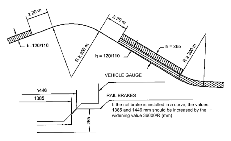
PASSING TRACKS:U.K.
On the passing tracks of marshalling humps Rmin = 500 m, and the height of obstacle gauge above the running surface is h = 0 mm across the whole vehicle gauge width (= 1 700 mm from track centreline). The longitudinal area where h = 0 spreads from the point of 20 m before the convex area on the top of the hump to the point of 20 m after the concave area at the valley of the hump. The obstacle gauge for the marshalling yard is valid outside this area (RAMO item 2.9 and RAMO 2 Annex 2, related to the gauge of marshalling yards, and also RAMO 2 Annex 5 related to the points of crossings).
FIN1/Appendix CReduction of the half-width according to the vehicle gauge FIN1, (reduction formulae)
1.General rulesU.K.
The cross dimensions of the vehicles computed according to the vehicle gauge (Appendix A) should be decreased by the quantities Es or Eu, so that, when the vehicle is in its least favourable position (without inclination on its suspension) and on a track of radius R = 150 m, with a track gauge of 1,544 m, no part of the vehicle protrude the half-width of the vehicle gauge FIN1 by more than (36/R + k) from the track centreline.
The centreline of the vehicle gauge coincides with the track centreline, this one being inclined if the track is canted.
Reductions are calculated according to formulae given in chapter 2.
2.Reduction formulae (in metres)U.K.
2.1Sections between bogie pivots or between end axlesU.K.


2.2Sections beyond bogie pivots or beyond end axles (vehicles with a overhang)U.K.


Notations:
Es, Es ∞ =
reduction of the gauge half-width for cross sections between bogie pivots or between end axles. Es and Es∞ should not be taken into account unless their values are positive;
Eu, Eu∞ =
reduction of the gauge half-width for cross sections beyond bogie pivots or beyond end axles. Eu and Eu∞ should not be taken into account unless their values are positive;
a =
distance between bogie pivots or between end axles(3);
n =
distance between the cross section considered and the nearest bogie pivot, or the nearest end axle or the fictional pivot if the vehicle has no fixed pivot;
p =
bogie wheelbase;
q =
is the sum of the play between the axle box and the axle itself and of the possible play between the axle box and the bogie frame measured from the middle position with ultimately worn components;
wiR =
possible transverse displacement of the bogie pivot, and the cradle in relation to the bogie frame or, for vehicles without bogie pivot, possible displacement of the bogie frame in relation to the vehicle frame measured from the middle position towards the internal side of the curve (varies according to the curve radius);
waR =
comme wiR, but towards the outside of the curve;
w∞ =
as wiR, but on a straight track, from the middle position and towards both side;
l =
maximum track gauge in straight and in considered curved track = 1,544 m;
d =
distance between ultimately worn wheel flanges, measured 10 mm outwards the running circle = 1,492 m;
R =
curve radius;
If w is constant or varies linearly according to 1/R, the radius to be considered is 150 m.
In exceptional cases, the actual value of R ≥ 150 m should be used.
k =
allowable gauge protrusion (to be increased by the 36/R widening of obstacle gauge) without the inclination due to the suspension flexibility;
= 0 for h < 330 mm for vehicles able to run over rail brakes (see Appendix B1),
= 0,06 m for h < 600 mm,
= 0,075 m for h ≥ 600 mm.
h =
height above the running surface at the considered location, the vehicle being in its lowest position.
3.Reduction valuesU.K.
The half-width of vehicle cross-sections should be decreased:
3.1For sections between bogie pivots;U.K.
By the greater of values Es and Es∞ .
3.2For sections beyond bogie pivots;U.K.
By the greater of values Eu and Eu∞.
FIN1/Appendix D1GAUGE OF THE VEHICLE LOWER STEP
1.This norm concerns the step used either for high (550/1 800) or for low platforms (265/1 600).U.K.
To avoid a uselessly wide gap between the step and the platform edge and taking account of the lower vehicle step and of high platforms (550/1 800 mm), the value 1,7 - E can be exceeded in compliance with Appendix C, if a fixed step is concerned. In such a case, the calculations hereafter should be applied which allow checking that, in spite of the protrusion, the step will not reach the platform. The coach should be examined in its lowest position in relation to the running surface.
2.Distance between the track centreline and the platform:U.K.
3.Room required for the step:  U.K.
U.K.
3.1Step located between bogie pivots:  U.K.
U.K.
3.2Step located beyond bogie pivots:U.K.

4.Notations (values in metres):U.K.
As, Au =
distance between the track centreline and the outer edge of a step;
B =
distance between the vehicle centreline and the outer edge of the step;
a =
distance between bogie pivots or between end axles;
n =
distance of the step cross section most remote from the bogie pivot;
p =
bogie wheel base;
q =
possible transverse displacement due to the play between the axle and the axle box added with the play between the axle box and the bogie frame measured from the middle position with ultimately worn components;
wiR =
possible transverse displacement of the bogie pivot and the cradle, measured from the middle position towards the internal side of the curve;
waR =
comme wiR, but towards the outside of the curve;
wiR/aR =
maximum value in considered curved track (for fixed steps);
= 0,005 m (for controlled steps which for v ≤ 5 km/h unfurl automatically);
l =
maximum track gauge in straight and in considered curved track = 1,544 m;
d =
distance between ultimately worn wheel flanges, measured 10 mm outwards the running circle = 1,492 m;
R =
Curve radius =500 m …. ∞;
t =
allowed tolerance (0,02 m) for the displacement of the rail towards the platform between two maintenance actions.
5.Rules related to the transverse distance between the step and the platform:U.K.
5.1Distance AV = L - As/u should be at least 0,02 m.U.K.
5.2On a straight track, with a coach in its middle position and a platform in its nominal location, a 150 mm distance between vehicle and platform is considered as sufficiently small. Anyway the smallest value should be sought for this distance. In the opposite case, the check is made on a straight and on a curved track where As/u is maximum.U.K.
6.Gauge checkU.K.
Gauge check for the lower steps should be carried out on a straight track and on a 500 m curve, if value w is constant or varies linearly according to 1/R. Otherwise, the check should be carried out on a straight track and on curve where As/u is maximum.
7.Display of the outputsU.K.
Formulae used, inserted and resulting values should be displayed in an easily understood manner.
FIN1/Appendix D2Gauge of outwards opening doors and of opened steps for coaches and multiple units
1.To avoid a uselessly wide gap between the step and the platform edge, the value 1,7 — E (see UIC Leaflet 560 § 1.1.4.2) can be exceeded in compliance with Appendix C, in the design of an outwards opening door with a step in open or closed position, or when the door and the step are moving between open and closed positions. In this case the checks hereafter should be carried out, among others to evidence that, in spite of the additional displacement, neither the door nor the step interfere with the fixed equipment (RAMO item 2.9 Annex 2). In the calculations the coach should be examined in its lowest position in relation to the running surface.U.K.
Hereafter, the word door includes the step as well.
NOTE: Appendix D2 may also be used to check the outer rear-view mirror of a loco and motor car the mirror being in open position. During normal line traffic the mirror is closed in a position recessed inside the body gauge.
2.The distance between the track centreline and the fixed equipment is:  ;U.K.
;U.K.
AT =
1,8 m when h < 600 mm,
AT =
1,92 m when 600 < h ≤ 1 300 mm,
AT =
2,0 m when h > 1 300 mm.
3.Room required for to the door:U.K.
3.1.Door located between bogie pivots: 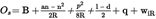 U.K.
U.K.
3.2Door located beyond bogie pivots:  U.K.
U.K.
4.Notations (values in metres):U.K.
AT =
nominal distance between the track centreline and the fixed equipment (on a straight track);
h =
height above the running surface at the considered location, the vehicle being in its lowest position;
Os, Ou =
distance allowed between the track centreline and the door edge, when the door is in its most protruding position;
B =
distance between the vehicle centreline and the door edge, when the door is in its most protruding position;
a =
distance between bogie pivots or between end axles;
n =
distance of the door cross section most remote from the bogie pivot;
p =
bogie wheel base;
q =
possible transverse displacement due to the play between the axle and the axle box added with the play between the axle box and the bogie frame measured from the middle position with ultimately worn components;
wiR =
possible transverse displacement of the bogie pivot and the cradle, measured from the middle position towards the internal side of the curve;
waR =
as wiR, but towards the outside of the curve;
wiR/aR =
0,02 m, maximum value for speeds less than 30 km/h (UIC 560);
l =
maximum track gauge in straight and in considered curved track = 1,544 m;
d =
distance between ultimately worn wheel flanges, measured 10mm outwards the running circle =1,492 m
R =
Curve radius:
for h < 600 mm, R = 500 m,
for h ≥ 600 mm, R = 150 m.
t =
allowed tolerance (0,02 m) for the displacement of the rail towards the fixed equipment between two maintenance actions.
5.Rules related to the transverse distance between the door and the fixed equipment:U.K.
Distance OV = L - Os/u should be at least 0,02 m.
6.Gauge checkU.K.
Door gauge check should be carried out on a straight track and on a 500/150-m curve, if value w varies linearly according to 1/R. Otherwise, the check should be carried out on a straight track and on curve where Os/u is maximum.
7.Display of the outputsU.K.
Formulae used, inserted and resulting values should be displayed in an easily understood manner.
FIN1/Appendix EPantograph and non-insulated live parts

Any non-insulated live part cannot be placed in the dashed area (25 kV).
1)Es or Eu must be added in the transversal direction according to Appendix C.U.K.
(1)
Formulae are based on the position of a rail brake and other shunting devices of marshalling humps shown in Appendix B3.
(2)
Formulae are based on the vehicle gauge for tracks on marshalling humps as shown in Appendix B3
(3)
If the vehicle has no actual bogie pivot, a and n should be determined on the base of a fictional pivot located at the intersection of the longitudinal centrelines of the bogie and of the frame, the vehicle being in middle position (0,026 + q + w = 0) on a curved track of radius 150 m. If the distance between the pivot calculated by this manner and the bogie centre point is denoted y, the term p2 should be replaced by p2 - y2 in reduction formulae.
Options/Help
Print Options
PrintThe Whole Decision
PrintThe Whole Annex
You have chosen to open the Whole Decision
The Whole Decision you have selected contains over 200 provisions and might take some time to download. You may also experience some issues with your browser, such as an alert box that a script is taking a long time to run.
Would you like to continue?
You have chosen to open Schedules only
The Schedules you have selected contains over 200 provisions and might take some time to download. You may also experience some issues with your browser, such as an alert box that a script is taking a long time to run.
Would you like to continue?
Legislation is available in different versions:
Latest Available (revised):The latest available updated version of the legislation incorporating changes made by subsequent legislation and applied by our editorial team. Changes we have not yet applied to the text, can be found in the ‘Changes to Legislation’ area.
Original (As adopted by EU): The original version of the legislation as it stood when it was first adopted in the EU. No changes have been applied to the text.
Point in Time: This becomes available after navigating to view revised legislation as it stood at a certain point in time via Advanced Features > Show Timeline of Changes or via a point in time advanced search.
See additional information alongside the content
Geographical Extent: Indicates the geographical area that this provision applies to. For further information see ‘Frequently Asked Questions’.
Show Timeline of Changes: See how this legislation has or could change over time. Turning this feature on will show extra navigation options to go to these specific points in time. Return to the latest available version by using the controls above in the What Version box.
Opening Options
Different options to open legislation in order to view more content on screen at once
More Resources
Access essential accompanying documents and information for this legislation item from this tab. Dependent on the legislation item being viewed this may include:
- the original print PDF of the as adopted version that was used for the EU Official Journal
- lists of changes made by and/or affecting this legislation item
- all formats of all associated documents
- correction slips
- links to related legislation and further information resources
Timeline of Changes
This timeline shows the different versions taken from EUR-Lex before exit day and during the implementation period as well as any subsequent versions created after the implementation period as a result of changes made by UK legislation.
The dates for the EU versions are taken from the document dates on EUR-Lex and may not always coincide with when the changes came into force for the document.
For any versions created after the implementation period as a result of changes made by UK legislation the date will coincide with the earliest date on which the change (e.g an insertion, a repeal or a substitution) that was applied came into force. For further information see our guide to revised legislation on Understanding Legislation.
More Resources
Use this menu to access essential accompanying documents and information for this legislation item. Dependent on the legislation item being viewed this may include:
- the original print PDF of the as adopted version that was used for the print copy
- correction slips
Click 'View More' or select 'More Resources' tab for additional information including:
- lists of changes made by and/or affecting this legislation item
- confers power and blanket amendment details
- all formats of all associated documents
- links to related legislation and further information resources
 All content is available under the Open Government Licence v3.0 except where otherwise stated. This site additionally contains content derived from EUR-Lex, reused under the terms of the Commission Decision 2011/833/EU on the reuse of documents from the EU institutions. For more information see the EUR-Lex public statement on re-use.