
[F1ANNEX VII U.K. METHOD OF MEASUREMENT OF RADIATED BROADBAND ELECTROMAGNETIC EMISSIONS FROM ELECTRICAL/ELECTRONIC SUB-ASSEMBLIES
Textual Amendments
F1 Substituted by Commission Directive 95/54/EC of 31 October 1995 adapting to technical progress Council Directive 72/245/EEC on the approximation of the laws of the Member States relating to the suppression of radio interference produced by spark-ignition engines fitted to motor vehicles and amending Directive 70/156/EEC on the approximation of the laws of the Member States relating to the type-approval of motor vehicles and their trailers.
1. General U.K.
1.1. The test method described in this Annex may be applied to ESAs which may be subsequently fitted to vehicles which comply with Annex IV. U.K.
1.2. Measuring apparatus U.K.
The measuring equipment shall comply with the requirements of publication No 16-1 (93) of the International Special Committee on Radio Interference (CISPR).
A quasi-peak detector shall be used for the measurement of broadband electromagnetic emissions in this Annex, or if a peak detector is used an appropriate correction factor shall be used depending on the interference pulse rate.
1.3. Test method U.K.
This test is intended to measure broadband electromagnetic emissions from ESAs.
2. Expression of results U.K.
The results of measurements shall be expressed in dB microvolts/m (microvolts/m), for 120 kHz band width. If the actual band width B (expressed in kHz) of the measuring apparatus differs from 120 kHz, the readings taken in microvolts/m shall be converted to 120 kHz band width through multiplication by a factor 120/B.
3. Measuring location U.K.
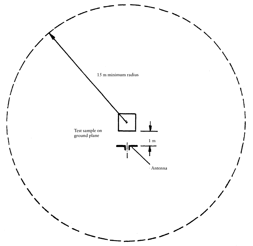
3.1. The test site shall comply with the requirements of publication No 16-1 (93) of the International Special Committee on Radio Interference (CISPR) (see Appendix 1 to this Annex). U.K.
3.2. The measuring set, test hut or vehicle in which the measurement set is located shall be outside the boundary shown in Appendix 1 to this Annex. U.K.
3.3. Enclosed test facilities may be used if correlation can be shown between the enclosed test facility and an approved outdoor site. Enclosed test facilities do not need to meet the dimensional requirements of Appendix 1 to this Annex other than the distance from the antenna to the ESA under test and the height of the antenna (see Figures 1 and 2 of Appendix 2 to this Annex). U.K.
3.4. Ambient U.K.
To ensure that there is no extraneous noise or signal of a magnitude sufficient to affect materially the measurement, measurements hall be taken before and after the main test. In both of these measurements, the extraneous noise or signal shall be at least 10 dB below the limits of interference given in paragraph 6.5.2.1 of Annex I, except for international narrowband ambient transmissions.
4. ESA state during tests U.K.
4.1. The ESA under test shall be in normal operation mode. U.K.
4.2. Measurements shall not be made while rain of other precipitation is falling on the ESA under test or within 10 minutes after such rain or other precipitation has stopped. U.K.
4.3. Test arrangements U.K.
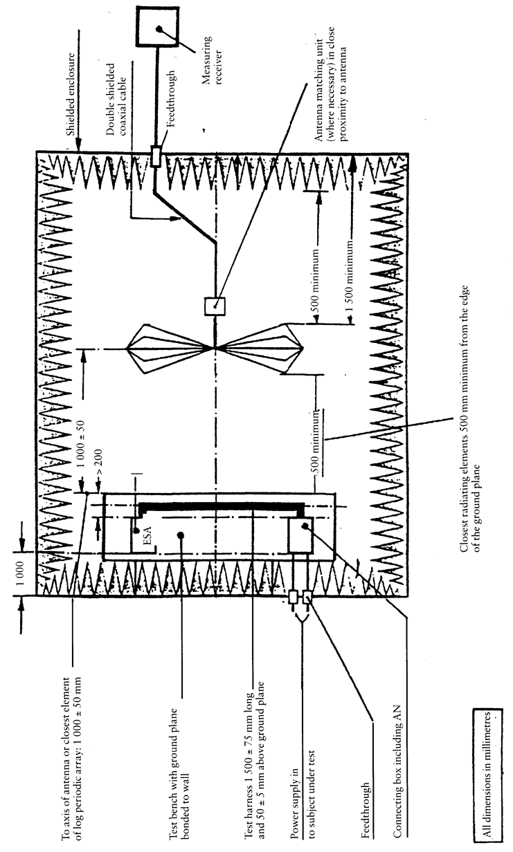
4.3.1. The ESA under test and its wiring harnesses shall be supported 50 ± 5 mm above a wooden or equivalent non-conducting table. However, if any part of the ESA under test is intended to be electrically bonded to a vehicle's metal bodywork, that part shall be placed on a ground plane and shall be electrically bonded to the ground plane. The ground plane shall be a metallic sheet with a minimum thickness of 0,5 mm. The minimum size of the ground plane depends on the size of the ESA under test but shall allow for the distribution of the ESA's wiring harness and components. The ground plane shall be connected to the protective conductor of the earthing system. The ground plane shall be situated at a height of 1,0 ± 0,1 m above the test facility floor and shall be parallel to it. U.K.
4.3.2. The ESA under test shall be arranged and connected according to its requirements. The power supply harness shall be positioned along, and within 100 mm of, the edge of the ground plane/table closest to the antenna. U.K.
4.3.3. The ESA under test shall be connected to the grounding system according to the manufacturer's installation specification, no additional grounding connections shall be permitted. U.K.
4.3.4. The minimum distance between the ESA under test and all other conductive structures, such as walls of a shielded ares (with the exception of the ground plane/table underneath the test object) must be 1,0 m. U.K.
4.4. Power shall be applied to the ESA under test via a 5 μH/50 Ω artificial network (AN) which shall be electrically bonded to the ground plane. The electrical supply voltage shall be maintained to ± 10 % of its nominal system operating voltage. Any ripple voltage shall be less than 1,5 % of the nominal system operating voltage measured at the AN monitoring port. U.K.
4.5. If the ESA under test consists of more than one unit, the interconnecting cables should ideally be the wiring harness as intended for use in the vehicle. If these are not available, the length between the electronic control unit and the AN shall be 1 500 ± 75 mm. All cables in the loom should be terminated as realistically as possible and preferably with real loads and actuators. If extraneous equipment is required for the correct operation of the ESA under test, compensation shall be made for the contribution it makes to the emissions measured. U.K.
5. Antenna type, position and orientation U.K.
5.1. Antenna type U.K.
Any linearly polarized antenna may be used provided it can be normalized to the reference antenna.
5.2. Height and distance of measurement U.K.
5.2.1. Height U.K.
The phase centre of the antenna shall be 150 ± 10 mm above ground plane.
5.2.2. Distance of measurement U.K.
The horizontal distance from the phase centre of tip of the antenna as appropriate, to the edge of the ground plane shall be 1,00 ± 0,05 m. No part of the antenna shall be closer than 0,5 m to the ground plane.
The antenna shall be placed parallel to a plane which is perpendicular to the ground plane and coincident with the edge of the ground plane along which the principal portion of the harness runs.
5.2.3. If the test is carried out in a facility enclosed for radio frequency electromagnetic screening purposes, the antenna's receiving elements shall be no closer than 0,5 m to any radio absorbent material and no closer than 1,5 m to the wall of the enclosed facility. There must be no absorbent material between the receiving antenna and the ESA under test. U.K.
5.3. Antenna orientation and polarization U.K.
At the measuring point, readings shall be taken both with the antenna in a vertical and in a horizontal polarization.
5.4. Readings U.K.
The maximum of the two readings taken (in accordance with paragraph 5.3) at each spot frequency shall be taken as the characteristic reading at the frequency at which the measurements were made.
6. Frequencies U.K.
6.1. Measurements U.K.
Measurements shall be made throughout the 30 to 1 000 MHz frequency range. An ESA is considered as very likely to satisfy the required limits over the whole frequency range if it satisfies them at the following 13 frequencies in the range, e.g.: 45, 65, 90, 120, 150, 190, 230, 280, 380, 450, 600, 750 and 900 MHz.
In the event that the limit is exceeded during the test, investigations shall be made to ensure that this is due to the ESA and not to background radiation.
6.1.1. The limits apply thorughout the frequency range 30 to 1 000 MHz. U.K.
6.1.2. Measurements can be performed with either quasi-peak or peak detectors. The limits given in paragraphs 6.2 and 6.5 are for quasi-peak. If peak is used, add 38 dB for 1 MHz band width or subtract 22 dB for 1 kHz band width. U.K.
6.2. Tolerances U.K.
| Spot frequency (MHz) | Tolerance (MHz) |
|---|---|
| 45, 65, 90, 120, 150, 190 and 230 | ± 5 |
| 280, 380, 450, 600, 750 and 900 | ± 20 |
The tolerances apply to frequencies quoted and are intended to avoid interference from transmissions operating on or near the nominal spot frequencies during the time of measurement.
Appendix 1 Figure 1 Electrical/electronic sub-assembly test area boundary
Appendix 2
Radiated electromagnetic emissions from an ESA test layout (General plan view) U.K.
Appendix 2

Radiated electromagnetic emissions from an ESA view of test bench plane of longitudinal symmetry] U.K.