- Latest available (Revised)
- Point in Time (01/07/2013)
- Original (As adopted by EU)
Directive 95/28/EC of the European Parliament and of the Council (repealed)Show full title
Directive 95/28/EC of the European Parliament and of the Council of 24 October 1995 relating to the burning behaviour of materials used in the interior construction of certain categories of motor vehicle (repealed)
You are here:
- Directives originating from the EU
- 1995 No. 28
- Whole Directive
- Previous
- Next

What Version
Advanced Features
- Show Geographical Extent(e.g. England, Wales, Scotland and Northern Ireland)
- Show Timeline of Changes
More Resources
Revised version PDFs
- Revised 01/11/20140.44 MB
- Revised 01/07/20131.10 MB
- Revised 01/01/20070.45 MB
- Revised 01/05/20040.45 MB
Legislation originating from the EU
When the UK left the EU, legislation.gov.uk published EU legislation that had been published by the EU up to IP completion day (31 December 2020 11.00 p.m.). On legislation.gov.uk, these items of legislation are kept up-to-date with any amendments made by the UK since then.


This item of legislation originated from the EU
Legislation.gov.uk publishes the UK version. EUR-Lex publishes the EU version. The EU Exit Web Archive holds a snapshot of EUR-Lex’s version from IP completion day (31 December 2020 11.00 p.m.).
Changes over time for: Directive 95/28/EC of the European Parliament and of the Council (repealed)
Version Superseded: 01/11/2014
Status:
EU Directives are published on this site to aid cross referencing from UK legislation. Since IP completion day (31 December 2020 11.00 p.m.) no amendments have been applied to this version.
Directive 95/28/EC of the European Parliament and of the Council
of 24 October 1995
relating to the burning behaviour of materials used in the interior construction of certain categories of motor vehicle (repealed)
THE EUROPEAN PARLIAMENT AND THE COUNCIL OF THE EUROPEAN UNION,
Having regard to the Treaty establishing the European Community, and in particular Article 100a thereof,
Having regard to the proposal from the Commission(1),
Having regard to the opinion of the Economic and Social Committee(2),
Acting in accordance with the procedure laid down in Article 189b of the Treaty(3),
Whereas the internal market comprises an area without internal frontiers in which the free movement of goods, persons, services and capital is ensured; whereas it is important to adopt measures to that end;
Whereas the technical requirements which certain vehicle categories must satisfy pursuant to national law relate, inter alia, to the burning behaviour of materials used in the interior construction of certain categories of motor vehicle;
Whereas these requirements differ from one Member State to another;
Whereas it is therefore necessary that all Member States adopt the same requirements either in addition to or in place of their existing rules in order, in particular, to allow the EEC type-approval procedure which was the subject of Council Directive 70/156/EEC of 6 February 1970 on the approximation of the laws of the Member States relating to the type-approval of motor vehicles and their trailers(4), to be further implemented;
Whereas this Directive will be one of the separate Directives of the EEC type-approval procedure which has been established by Directive 70/156/EEC; whereas, consequently, the provisions laid down in Directive 70/156/EEC relating to vehicle systems, components and separate technical units shall apply for the purposes of this Directive;
Whereas it is appropriate to refer to Council Directive 77/649/EEC(5), which contains the procedure for determining the position of the seating reference point (the ‘R-point’);
Whereas, with a view to ensuring occupant and road safety, it is important that the materials used in the construction of the inside of bus and coach bodywork satisfy minimum requirements in order to avoid or at least retard development of flames such that it allows occupants to evacuate the vehicle in the event of fire;
Whereas it is desirable to introduce alternative routes for the type-approval of vehicles as systems pursuant to this Directive, i. e. either on the basis of tests of the burning behaviour of the interior materials used in motor vehicles or on the basis of an EEC component type-approval for each material and/or equipment such as seats, curtains, etc. to be fitted in the interior construction of these vehicles whereby the correct installation of such approved materials and/or equipment has to be checked,
HAVE ADOPTED THIS DIRECTIVE:
Article 1U.K.
For the purposes of this Directive:
‘vehicle’: means any vehicle as defined in Article 2 of Directive 70/156/EEC,
‘component’: means a device as defined in Article 2 of Directive 70/156/EEC.
Article 2U.K.
Member States may not refuse:
EEC type-approval or national type-approval for a vehicle or refuse or prohibit the sale, registration, entry into service or use of a vehicle on grounds relating to the burning behaviour of materials used in the interior construction of its bodywork,
EEC type-approval or national type-approval for a component used in the interior construction of the vehicle bodywork or prohibit its sale or use on grounds relating to the burning behaviour of the materials used in its construction,
if the relevant requirements set out in Annexes I, IV, V and VI to this Directive are satisfied.
Article 3U.K.
1.Member States shall adopt and publish the laws, regulations are administrative provisions necessary to comply with this Directive within 18 months of the date of its adoption. They shall forthwith inform the Commission thereof.
From the abovementioned date, Member States may no longer prohibit the initial entry into service of vehicles or the sale or use of components complying with this Directive.
They shall apply these provisions 48 months following the date of adoption of this Directive.
2.When Member States adopt these measures, they shall contain a reference to this Directive or shall be accompanied by such reference on the occasion of their official publication. The method of making such reference shall be laid down by Member States.
Article 4U.K.
This Directive is addressed to the Member States.
ANNEX IU.K.SCOPE, DEFINITIONS, APPLICATION FOR EEC TYPE-APPROVAL, GRANTING OF EEC-TYPE-APPROVAL, SPECIFICATIONS, MODIFICATIONS OF THE TYPE, CONFORMITY OF PRODUCTION, REQUIREMENTS CONCERNING INSTALLATION IN THE VEHICLE
1.ScopeU.K.
This Directive applies to the burning behaviour (ignitability, burning rate and melting behaviour) of interior materials used in vehicles of category M3 carrying more than 22 passengers, not being designed for standing passengers and urban use (city buses).
Member States which, prior to the date mentioned in Article 3 (1), third subparagraph of the Directive, had legislation applying to vehicle categories other than that mentioned above may continue to apply that legislation provided that they accept type-approval for other vehicle categories which comply with the provisions of this Directive.
2.DefinitionsU.K.
For the purpose of this Directive:
2.1.‘Approval of a vehicle’ means the approval of a vehicle type such as defined in point 2.2 with regard to the burning behaviour of the interior components used in the passenger compartment.U.K.
2.2.‘Vehicle type’ means vehicles which do not differ in such essential respects as:U.K.
2.2.1.The devices such as materials, seats, curtains, separation walls, etc. used in the passenger compartment.U.K.
2.2.2.The mass of the devices used, in so far as they have an effect on the performance prescribed in this Directive.U.K.
2.2.3.The optional arrangements or fittings in so far as they have no detrimental effect on the performance prescribed in this Directive.U.K.
2.3.‘Approval of a component’ means an approval for devices, such as materials, seats, curtains, separation walls, etc.U.K.
2.4.‘Type of a component’ means components which do not differ in such essential respects as:U.K.
2.4.1.the base material(s) (e. g. wool, plastic, rubber, blended materials).U.K.
2.4.2.the intended use (seat upholstery, roof lining, etc.).U.K.
2.4.3.the manufacturer's type designation.U.K.
2.4.4.the number of layers in the case of composite materials.U.K.
2.4.5.other characteristics in so far as they have an appreciable effect on the performance prescribed in this Directive.U.K.
2.5.‘Passenger compartment’ means the space for occupant accommodation (including bar, kitchen, toilet, etc.), bounded by:U.K.
the roof,
the floor,
the side walls,
the doors,
the outside glazing,
the rear compartment bulkhead, or the plane of the rear seat back support,
at the driver's side of the longitudinal vertical median plane of the vehicle, the vertical transversal plane through the driver's R-point as defined in Annex III to Directive 77/649/EEC,
at the opposite side of the longitudinal vertical median plane of the vehicle, the front bulkhead.
2.6.‘Seat’ means a structure which may or may not be integral with the vehicle structure, complete with trim, intended to seat one adult person. The term covers both an individual seat or part of a bench seat intended to seat one adult person.U.K.
2.7.‘Group of seats’ means either a bench-type seat, or seats which are separate but side by side (i. e. with the foremost anchorages of one seat in line with or forward of the rearmost anchorages and in line with or behind the foremost anchorages of another seat) and which accommodate one or more seated adult persons.U.K.
2.8.‘Bench seat’ means a structure complete with trim, intended to seat more than one adult person.U.K.
2.9.‘Burning rate’ means the quotient of the burnt distance measured according to Annex IV and/or VI to this Directive and the time taken to burn this distance. It is expressed in millimetres per minute.U.K.
2.10.‘Composite material’ means a material composed of several layers of similar or different materials intimately held together at their surfaces by cementing, bonding, cladding, welding, etc.U.K.
When different materials are connected together intermittently (for example, by sewing, high-frequency welting, riveting), such materials shall not be considered as composite materials.
2.11.‘Exposed face’ means the side of a material which is facing towards the passenger compartment when the material is mounted in the vehicle.U.K.
2.12.‘Upholstery’ means the combination of interior padding and surface finish material which together constitute the cushioning of the seat frame.U.K.
2.13.‘Interior lining(s)’ means material(s) that (together) constitute(s) the surface finish and substrate of a roof, wall or floor.U.K.
3.Application for EEC vehicle type-approvalU.K.
3.1.The application for EEC type-approval pursuant to Article 3 (4) of Directive 70/156/EEC of a vehicle type with regard to the burning behaviour of the materials used in the passenger compartment shall be submitted by the vehicle manufacturer.U.K.
3.2.A model of the information document is given in Annex II, Appendix 1.U.K.
3.3.The following must be submitted to the technical service responsible for conducting the type-approval tests:U.K.
3.3.1.in the case of interior components without EEC type-approval: samples, the number of which is specified in items 7.2, 7.3 and 7.4 below, of the components used in the vehicles, which are representative of the type to be approved;U.K.
3.3.2.in the case of interior components already type-approved: the type approvals are to be enclosed in the application for the vehicle type-approval;U.K.
3.3.3.a vehicle representative of the type to be approved.U.K.
4.Application for EEC component type-approvalU.K.
4.1.The application of EEC component type-approval pursuant to Article 3 (4) of Directive 70/156/EEC for a type of interior material with regard to its burning behaviour shall be submitted by the manufacturer.U.K.
4.2.A model for the information document is given in Annex II, Appendix 2.U.K.
4.3.The following must be submitted to the technical service responsible for conducting the type-approval tests:U.K.
4.3.1.samples, the number of which is specified in items 7.2, 7.3 and 7.4 below. The samples shall be clearly and indelibly marked with the applicant's trade name or mark and the type designation;U.K.
4.3.2.for devices such as seats, curtains, separation walls, etc., the samples specified in 4.3.1 plus one complete device as mentioned above.U.K.
5.Granting of EEC type-approvalU.K.
5.1.If the relevant requirements are satisfied, EEC type-approval pursuant to Article 4 (3) and, if applicable, 4 (4), of Directive 70/156/EEC shall be granted.U.K.
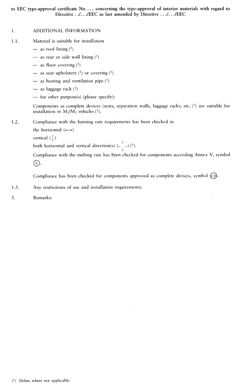
5.2.A model for the EEC type-approval certificate is given in:U.K.
5.2.1.Annex III, Appendix 1 for applications referred to in 3.1.U.K.
5.2.2.Annex III, Appendix 2 for applications referred to in 4.1.U.K.
5.3.An approval number in accordance with Annex VII to Directive 70/156/EEC shall be assigned to each type of vehicle and to each type of component approved. The same Member State shall not assign the same number to another type of vehicle or to another type of component.U.K.
6.MarkingU.K.
6.1.Every component conforming to a type approved under this Directive shall bear an EEC type-approval mark. This mark shall consist of:U.K.
6.1.1.a rectangle surrounding the lower case letter ‘e’ followed by the distinguishing number or letters of the Member State which has granted component type-approval:U.K.
| 1 | for Germany |
| 2 | for France |
| 3 | for Italy |
| 4 | for Netherlands |
| 5 | for Sweden |
| 6 | for Belgium |
| [F17 | for Hungary |
| 8 | for the Czech Republic] |
| 9 | for Spain |
| 11 | for the United Kingdom |
| 12 | for Austria |
| 13 | for Luxembourg |
| 17 | for Finland |
| 18 | for Denmark |
| [F219 | for Romania] |
| [F120 | for Poland] |
| 21 | for Portugal |
| 23 | for Greece |
| [F325 | for Croatia] |
| [F126 | for Slovenia |
| 27 | for Slovakia |
| 29 | for Estonia |
| 32 | for Latvia |
| [F234 | for Bulgaria] |
| 36 | for Lithuania |
| CY | for Cyprus] |
| IRL | for Ireland[F4;] |
| [F1MT | for Malta;] |
Textual Amendments
F1 Inserted by Act concerning the conditions of accession of the Czech Republic, the Republic of Estonia, the Republic of Cyprus, the Republic of Latvia, the Republic of Lithuania, the Republic of Hungary, the Republic of Malta, the Republic of Poland, the Republic of Slovenia and the Slovak Republic and the adjustments to the Treaties on which the European Union is founded.
F2 Inserted by Council Directive 2006/96/EC of 20 November 2006 adapting certain Directives in the field of free movement of goods, by reason of the accession of Bulgaria and Romania.
F3 Inserted by Council Directive 2013/15/EU of 13 May 2013 adapting certain directives in the field of free movement of goods, by reason of the accession of the Republic of Croatia.
F4 Deleted by Act concerning the conditions of accession of the Czech Republic, the Republic of Estonia, the Republic of Cyprus, the Republic of Latvia, the Republic of Lithuania, the Republic of Hungary, the Republic of Malta, the Republic of Poland, the Republic of Slovenia and the Slovak Republic and the adjustments to the Treaties on which the European Union is founded.
6.1.2.in the vicinity of the rectangle:U.K.
6.1.2.1.the base approval number contained in Section 4 of the type-approval number referred to in Annex VII to Directive 70/156/EEC preceded by the two figures indicating the sequence number assigned to the most recent major technical amendment to Directive …/…/EEC on the date EEC component type-approval was granted. In this Directive the sequence number is 00 (unamended form of the Directive);U.K.
6.1.2.2.symbols indicating the direction for which the burning rate has been determined:U.K.


6.1.2.3.the symbol  indicating that the component has been approved according to its melting behaviour (Annex V) and /or the symbol
  indicating that the component has been approved as a complete device, such as seats, separation walls, luggage racks, etc.U.K.
6.2.Where the seat has been approved as a component or where the cushion and the back of a seat or bench seat are covered with the same material, it is sufficient if the mark appears only once per seat or bench seat.U.K.
6.3.The mark must be affixed to the material in such a way as to be clearly legible and indelible even if the material is installed in a vehicle.U.K.
6.4.A model for the EEC component type-approval mark is shown in the Appendix of this Annex.U.K.
7.SpecificationsU.K.
7.1.The interior materials of the passenger compartment used in the vehicle to be type-approved shall undergo one or more of the tests mentioned in Annexes IV, V and VI.U.K.
7.2.From the following material(s) five samples in the case of an isotropic material or 10 samples in the case of a non-isotropic material (five for each direction), shall undergo the test described in Annex IV to this Directive:U.K.
material(s) used for the upholstery of any seat and its accessories (including the driver's seat),
material(s) used for the interior lining of the roof,
material(s) used for the interior lining of the side and rear walls, including separation walls,
material(s) with thermal and/or acoustic function,
material(s) used for the interior lining of the floor,
material(s) used for the interior lining of luggage-racks, heating and ventilation pipes,
material(s) used for the light fittings.
Furthermore, one sample shall be submitted to the technical service for future reference purposes.
7.2.1.The result of the test shall be considered satisfactory if, taking the worst test results into account, the horizontal burning rate is not more than 100 mm/minute or if the flame extinguishes before reaching the last measuring point.U.K.
7.3.From the following material(s) four samples, for both faces (if they are not identical), shall undergo the test described in Annex V:U.K.
material(s) used for the interior lining of the roof,
material(s) used for the interior lining of the luggage-racks, heating and ventilation pipes situated in the roof,
material(s) used for the lights situated in the luggage-racks and/or roof.
Furthermore, one sample shall be submitted to the technical services for future reference purposes.
7.3.1.The result of the test shall be considered satisfactory if, taking the worst test results into account, no drop is formed which ignites the cotton wool.U.K.
7.4.Three samples in the case of an isotropic material, or six samples in the case of a non-isotropic material, of the material(s) used for the curtains and blinds (and/or other hanging materials) shall undergo the test described in Annex VI.U.K.
Furthermore, one sample shall be submitted to the technical service for future reference purposes.
7.4.1.The result of the test shall be considered satisfactory if, taking the worst test results into account, the vertical burning rate is not more than 100 mm/minute.U.K.
7.5.Materials which are not required to undergo the tests described in Annexes IV to VI are:U.K.
7.5.1.parts made of metal or glass;U.K.
7.5.2.each individual seat accessory with a mass of non-metallic material less than 200 g. If the total mass of these accessories exceeds 400 g of non-metallic material per seat, then each material must be tested;U.K.
7.5.3.elements of which the surface area or the volume does not exceed respectively:U.K.
7.5.3.1.100 cm2 or 40 cm3 for the elements which are connected to an individual seating place;U.K.
7.5.3.2.300 cm2 or 120 cm3 per seat row and, at a maximum, per linear metre of the interior of the passenger compartment for these elements which are distributed in the vehicle and which are not connected to an individual seating place;U.K.
7.5.4.electric cables;U.K.
7.5.5.elements for which it is not possible to extract a sample in the prescribed dimensions as specified in paragraph 3.1 of Annex IV, paragraph 3 of Annex V and paragraph 3.1 of Annex VI.U.K.
8.Modification of the vehicle and material type and amendments to these approvalsU.K.
8.1.In the case of modifications of the type approved pursuant to this Directive, the provisions of Article 5 of Directive 70/156/EEC shall apply.U.K.
9.Conformity of productionU.K.
9.1.Measures to ensure the conformity of production shall be taken in accordance with the provisions laid down in Article 10 of Directive 70/156/EEC.U.K.
10.Requirements concerning installation of materials and equipment in the vehicle and/or in the devices approved as componentsU.K.
10.1.The materials and/or equipment used in the passenger compartment and/or in devices approved as components shall be so installed as to minimize the risk of flame development and flame propagation.U.K.
10.2.Such interior materials and/or equipment shall only be installed in accordance with their intended purposes and the test(s) which they have undergone (see 7.2, 7.3 and 7.4), especially in relation to their burning and melting behaviour (horizontal/vertical direction).U.K.
10.3.Any adhesive agent used to affix the interior material to its supporting structure shall not, as far as possible, exacerbate the burning behaviour of the material.U.K.
AppendixModel for the EEC component type-approval mark
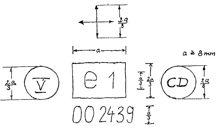
The above component type-approval mark shows that the interior material in question has been approved in Germany (e1) pursuant to this Directive (00) under the approval number 2439. The first two digits indicate that this component was approved according to the original form of this Directive. The additional symbol 
The symbols 

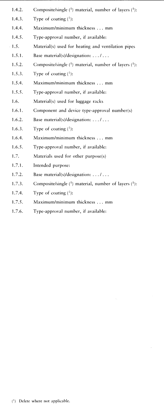
ANNEX IIU.K.INFORMATION DOCUMENTS
Appendix 1U.K.

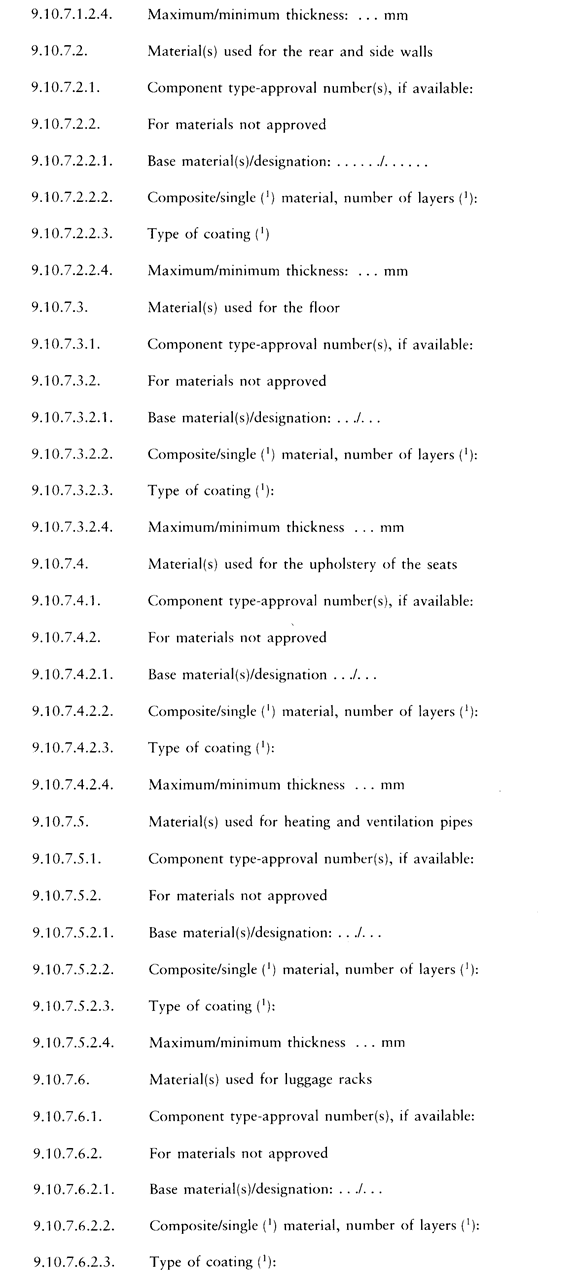
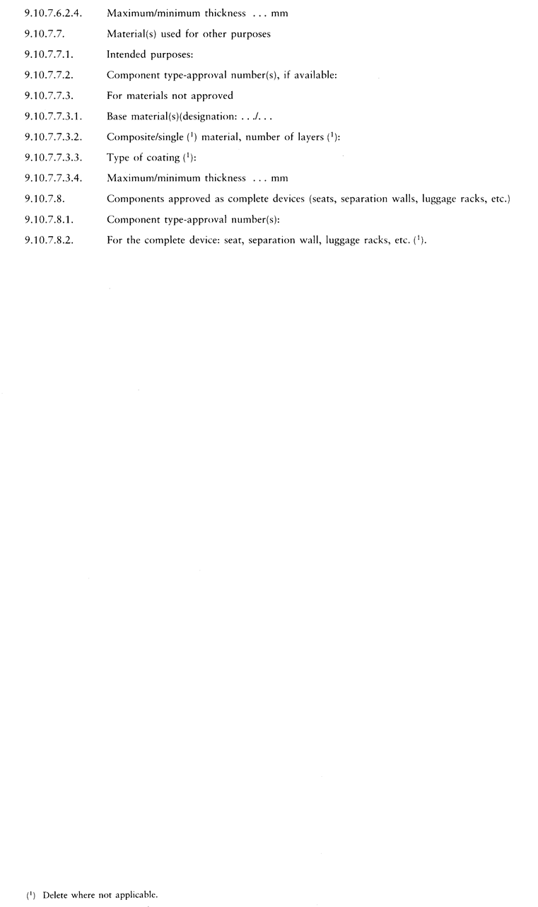
Appendix 2U.K.

ANNEX IIIU.K.EEC TYPE-APPROVAL CERTIFICATES
Appendix 1U.K.

AddendumU.K.

Appendix 2U.K.

AddendumU.K.
ANNEX IVU.K.TEST TO DETERMINE THE HORIZONTAL BURNING RATE OF MATERIALS
1.PrincipleU.K.
A sample is held horizontally in a U-shaped holder and is exposed to the action of a defined low-energy flame for 15 seconds in a combustion chamber, the flame acting on the free end of the sample. The test determines if and when the flame extinguishes or the time in which the flame passes a measured distance.
2.ApparatusU.K.
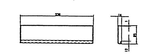
2.1.Combustion chamber (figure 1), preferably of stainless steel and having the dimensions given in figure 2. The front of the chamber contains a flame-resistant observation window, which may cover the front and which can be constructed as an access panel.U.K.
The bottom of the chamber has vent holes, and the top has a vent slot all around. The combustion chamber is placed on four feet, 10 mm high.
The chamber may have a hole at one end for the introduction of the sample holder containing the sample; in the opposite end, a hole is provided for the gas line. Melted material is caught in a pan (see figure 3) which is placed on the bottom of the chamber between vent holes without covering any vent hole area.


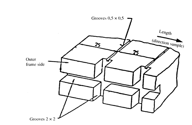
2.2.Sample holder, consisting of two U-shaped metal plates or frames of corrosion-proof material. Dimensions are given in figure 4.U.K.
The lower plate is equipped with pins, the upper one with corresponding holes in order to ensure a consistent holding of the sample. The pins also serve as the measuring points at the beginning and end of the burning distance.
A support shall be provided in the form of 0,25 mm diameter heat resistant wires spanning the frame at 25 mm intervals over the bottom U-shaped frame (see figure 5).
The plane of the lower side of samples shall be 178 mm above the floor plate. The distance of the front edge of the sample holder from the end of the chamber shall be 22 mm; the distance of the longitudinal sides of the sample holder from the sides of the chamber shall be 50 mm (all inside dimensions). (See figures 1 and 2).

2.3.Gas burner. The small ignition source is provided by a Bunsen burner having an inside diameter of 9,5 ± 0,5 mm. It is located in the test cabinet so that the centre of its nozzle is 19 mm below the centre of the bottom edge of the open end of the sample (see figure 2).U.K.
2.4.Test gas. The gas supplied to the burner shall have a calorific value near 38 MJ/m3 (for example natural gas).U.K.
2.5.Metal comb, at least 110 mm in length, with seven to eight smooth rounded teeth per 25 mm.U.K.
2.6.Stop-watch, accurate to 0,5 seconds.U.K.
2.7.Fume cupboard. The combustion chamber may be placed in a fume cupboard assembly provided that the internal volume is at least 20 times, but not more than 110 times, greater than the volume of the combustion chamber and provided that no single height, width, or length dimension of the fume cupboard is greater than 2 1/2 times either of the other two dimensions.U.K.
Before the test, the vertical velocity of the air through the fume cupboard shall be measured 100 mm in front of and behind the final position where the combustion chamber will be located. It shall be between 0,10 and 0,30 m/s in order to avoid possible discomfort, by combustion products, to the operator. It is possible to use a fume cupboard with a natural ventilation and an appropriate air velocity.
3.SamplesU.K.
3.1.Shape and dimensionsU.K.
3.1.1.The shape and dimensions of samples are given in figure 6. The thickness of the sample corresponds to the thickness of the product to be tested. It shall not be more than 13 mm. When taking the sample permits, the sample shall have a constant section over its entire length.U.K.

3.1.2.If the shape and dimensions of a product do not permit taking a sample of the given size, the following minimum dimensions shall be maintained:U.K.
(a)
for samples having a width of 3 to 60 mm, the length shall be 356 mm. In this case the material is tested in the product's width;
(b)
for samples having a width of 60 to 100 mm, the length shall be at least 138 mm. In this case the potential burning distance corresponds to the length of the sample, the measurement starting at the first measuring point.
3.2.SamplingU.K.
The samples shall be taken from the material under test. In materials having different burning rates in different material directions, each direction has to be tested. The samples are to be taken and placed in the test apparatus so that the highest burning rate will be measured.
When the material is supplied in widths, a length of at least 500 mm shall be cut covering the entire width. From this the samples shall be taken so as to be at least 100 mm from the material edge and equidistant from each other.
Samples shall be taken in the same way from finished products, when the shape of the product permits. When the thickness of the product is more than 13 mm, it shall be reduced to 13 mm by a mechanical process applied to the side which does not face the occupant compartment. If it is impossible, the test shall be carried out, in accordance with the Technical Service, on the initial width of the material which shall be mentioned in the test report.
Composite materials (see point 2.10 of Annex I) shall be tested as if they were of uniform construction.
In the case of materials made of superimposed layers of different composition which are not composite materials, all the layers of material included within a depth of 13 mm from the surface facing towards the passenger compartment shall be tested individually.
3.3.ConditioningU.K.
The samples shall be conditioned for at least 24 hours but not more than 7 days at a temperature of 23 ± 2 °C and a relative humidity of 50 ± 5 % and shall be maintained under these conditions until immediately prior to testing.
4.ProcedureU.K.
4.1.Place samples with napped or tufted surfaces on a flat surface and comb twice against the nap using the comb ( 2.5).U.K.
4.2.Place the sample in the sample holder (2.2) so that the exposed side will be downwards to the flame.U.K.
4.3.Adjust the gas flame to a height of 38 mm using the mark in the chamber, the air intake of the burner being closed. Before starting the first test, the flame shall burn at least for 1 min for stabilization.U.K.
4.4.Push the sample-holder into the combustion chamber so that the end of the sample is exposed to the flame, and after 15 seconds cut off the gas flow.U.K.
4.5.The measurement of the burning time starts at the moment when the foot of the flame passes the first measuring point. Observe the flame propagation on the side burning faster than the other (upper or lower side).U.K.
4.6.Measurement of burning time is completed when the flame has come to the last measuring point or when the flame extinguishes before coming to the last measuring point. If the flame does not reach the last measuring point, measure the burnt distance up to the point where the flame extinguished. Burnt distance is the decomposed part of the sample, which is destroyed on its surface or in the interior by burning.U.K.
4.7.In so far as the sample does not ignite or does not continue burning after the burner has been extinguished, or when the flame extinguishes before reaching the first measuring point, so that no burning time is measured note in the test report that the burning rate is 0 mm/min.U.K.
4.8.When running a series of tests or repeat tests, ensure that the combustion chamber and sample holder have a maximum temperature of 30 °C before starting the next test.U.K.
5.CalculationU.K.
The burning rate, B(6), in millimetres per minute, is given by the formula

where:
s is the burnt distance, in millimetres;
t is the time, in seconds, to burn distance s.
ANNEX VU.K.TEST TO DETERMINE THE MELTING BEHAVIOUR OF MATERIALS
1.PrincipleU.K.
A sample is placed in a horizontal position and is exposed to an electric radiator. A receptacle is positioned under the specimen to collect the resultant drops.
Some cotton wool is put in this receptacle in order to verify if any drop is flaming.
2.ApparatusU.K.
The apparatus shall consist of (figure 1):
(a)
an electric radiator;
(b)
a support for the sample with grill;
(c)
a receptacle (for resultant drops);
(d)
a support (for the apparatus).
2.1.The source of heat is an electric radiator with a useful output of 500 W. The radiating surface must be made of a transparent quartz plate with a diameter of 100 ± 5 mm.U.K.
The radiated heat from the apparatus, measured on a surface which is situated parallel to the surface of the radiator at a distance of 30 mm, shall be 3 W/cm2.
2.2.CalibrationU.K.
For calibration of the radiator, a heat flux meter (radiometer) of the Gardon (foil) type with a design range not exceeding 10 W/cm2 shall be used.
The target receiving radiation, and possibly to a small extent convection, shall be flat, circular, not more than 10 mm in diameter and coated with a durable matt black finish. The target shall be contained within a watercooled body the front face of which shall be of highly polished metal, flat, coinciding with the plane of the target and circular, with a diameter of about 25 mm.
Radiation shall not pass through any window before reaching the target. The instrument shall be robust, simple to set up and use, insensitive to draughts, and stable in calibration. The instrument shall have an accuracy of within ± 3 % and a repeatability within 0,5 %.
The calibration of the heat flux meter shall be checked whenever a recalibration of the radiator is carried out, by comparison with an instrument held as a reference standard and not used for any other purpose. The reference standard instrument shall be fully calibrated at yearly intervals in accordance with a national standard.
2.2.1.Calibration checkU.K.
The irradiance produced by the power input which the initial calibration has shown to correspond to an irradiance of 3 W/cm2 shall be frequently checked (at least once every 50 operating hours) and the apparatus shall be recalibrated if such a check reveals a deviation greater than 0,06 W/cm2.
2.2.2.Calibration procedureU.K.
The apparatus shall be placed in an environment essentially free of air currents (not more than 0,2 m/s).
Place the heat flux meter in the apparatus in the specimen position so that the target of the heat flux meter is located centrally within the radiator surface.
Switch on the electricity supply and establish the power input of the controller required to produce irradiance at the centre of the radiator surface of 3 W/cm2. Adjustment to the power unit to record 3 W/cm2 should be followed by a five minute-period without further adjustment to ensure equilibrium.
2.3.The support for the samples shall be a metallic ring (figure 1). On top of this support a grill, made of stainless steel-wire, is placed with the following dimensions:U.K.
interior diameter: 118 mm,
dimension of the holes: 2,10 mm square,
diameter of the steel-wire: 0,70 mm.
2.4.The receptacle shall consist of a cylindrical tube with an interior diameter of 118 mm and a depth of 12 mm.U.K.
The receptacle shall be filled with cotton wool.
2.5.A vertical column shall support the items specified in paragraph 2.1, 2.3 and 2.4.U.K.
The radiator is placed on top of the support in a manner such that the radiating surface is horizontal and the radiation is downwards.
A lever/pedal shall be provided in the column to lift the support of the radiator slowly. It shall also be provided with a catch in order to ensure that the radiator can be brought back in its normal position.
In their normal position, the axes of the radiator, the support for the sample and the receptacle must coincide.
3.SamplesU.K.
The test samples shall measure: 70 mm x 70 mm.
Samples shall be taken in the same way from finished products, when the shape of the product permits. When the thickness of the product is more than 13 mm, it shall be reduced to 13 mm by a mechanical process applied to the side which does not face the occupant compartment. If it is impossible, the test shall be carried out, in accordance with the Technical Service, on the initial width of the material which shall be mentioned in the test report.
Composite materials (see 2.8 of Annex I) shall be tested as if they were of uniform construction.
In the case of materials made of superimposed layers of different composition which are not composite materials, all the layers of material included within a depth of 13 mm from the surface facing towards the passenger compartment shall be tested individually.
The total mass of the sample to be tested shall be at least 2 g. If the mass of one sample is less, a sufficient number of samples shall be added.
If the two faces of the material differ, both faces must be tested, which means that eight samples are to be tested.
The samples and the cotton wool shall be conditioned for at least 24 hours at a temperature 23 ± 2 ° C and a relative humidity of 50 ± 5 % and shall be maintained under these conditions until immediately prior to testing.
4.ProcedureU.K.
The sample is placed on the support and the latter is so positioned that the distance between the surface of the radiator and the upperside of the sample is 30 mm.
The receptacle, including the cotton wool, is placed beneath the grill of the support at a distance of 300 mm.
The radiator is put aside, so that it cannot radiate on the sample, and switched on. When it is on full capacity it is positioned above the sample and timing is started.
If the material melts or deforms, the height of the radiator is modified to maintain the distance of 30 mm.
If the material ignites, the radiator is put aside three seconds afterwards. It is brought back in position when the flame has extinguished and the same procedure is repeated as frequently as necessary during the first five minutes of the test.
After the fifth minute of the test:
(i)
If the sample has extinguished (whether or not it has ignited during the first five minutes of the test) leave the radiator in position even if the sample reignites.
(ii)
If the material is flaming, await extinction before bringing the radiator into position again.
In either case, the test must be continued for an additional five minutes.
5.ResultsU.K.
Observed phenomena shall be noted in the test-report, such as:
the fall of drops, if any, whether flaming or not,
if ignition of the cotton wool has taken place

ANNEX VIU.K.TEST TO DETERMINE THE VERTICAL BURNING RATE OF MATERIALS
1.PrincipleU.K.
This test consists of exposing samples, held in a vertical position, to a flame and determining the speed of propagation of the flame over the material to be tested.
2.ApparatusU.K.
The apparatus shall consist of:
(a)
a specimen holder;
(b)
a burner;
(c)
a ventilation system to extract gas and combustion products;
(d)
a template;
(e)
marker threads of white mercerized cotton threads having a maximum linear density of 50 tex.
2.1.The specimen holder shall consist of a rectangular frame 560 mm high and shall have two rigidly connected parallel rods spaced 150 mm apart on which pins shall be fitted for mounting the test specimen which is located in a plane at least 20 mm from the frame. The mounting pins shall be not greater than 2 mm in diameter and at least 27 mm long. The pins shall be located on the parallel rods at locations shown in figure 1. The frame shall be fitted onto a suitable support to maintain the rods in a vertical orientation during testing. (For the purpose of locating the specimen on the pins in a plane away from the frame, spacer stubs 2 mm in diameter may be provided adjacent to the pins).U.K.
2.2.The burner is described in figure 3.U.K.
The gas supplied to the burner can be either commercial propane gas or commercial butane gas.
The burner shall be positioned in front of, but below, the specimen such that it lies in a plane passing through the vertical centreline of the specimen and perpendicular to its face (see figure 2), such that the longitudinal axis is inclined upwards at 30 ° to the vertical towards the lower edge of the specimen. The distance between the tip of the burner and the lower edge of the specimen shall be 20 mm.
2.3.The test apparatus may be placed in a fume cupboard assembly provided that the internal volume is at least 20 times, but not more than 110 times, greater than the volume of the test apparatus and provided that no single height, width, or length dimension of the fume cupboard is greater than 2 1/2 times either of the other two dimensions. Before the test, the vertical velocity of the air through the fume cupboard shall be measured 100 mm in front of and behind the final position where the test apparatus will be located. It shall be between 0,10 and 0,30 m/s in order to avoid possible discomfort, by combustion products, to the operator. It is possible to use a fume cupboard with a natural ventilation and an appropriate air velocity.U.K.
2.4.A flat rigid template made of suitable material and of a size corresponding to the size of the specimen shall be used. Holes approximately 2 mm in diameter shall be drilled in the template and positioned so that the distances between the centres of the holes correspond to the distances between the pins on the frames (see figure 1). The holes shall be located equidistant about the vertical centrelines of the template.U.K.
3.SamplesU.K.
3.1.The samples dimensions are: 560 × 170 mm.U.K.
3.2.The samples shall be conditioned for at least 24 hours at a temperature of 23 ± 2 °C and a relative humidity of 50 ± 5 % and shall be maintained under these conditions until immediately prior to testing.U.K.
4.ProcedureU.K.
4.1.The test shall be carried out in an atmosphere having a temperature between 10° and 30 °C and a relative humidity between 15 % and 80 %.U.K.
4.2.The burner shall be preheated for 2 minutes. The flame height shall be adjusted to 40 ± 2 mm measured as the distance between the top of the burner tube and the tip of the yellow part of the flame when the burner is vertically oriented and the flame is viewed in dim light.U.K.
4.3.The specimen shall be placed on the pins of the test frame, making certain that the pins pass through the points marked off from the template and that the specimen is at least 20 mm removed from the frame. The frame shall be fitted on the support so that the specimen is vertical.U.K.
4.4.The marker threads shall be attached horizontally in front of the specimen at the locations shown in figure 1. At each location, a loop of thread shall be mounted so that the two segments are spaced 1 mm and 5 mm from the plane of the front of the specimen.U.K.
Each loop shall be attached to a suitable timing device. Sufficient tension shall be imposed to the thread to maintain its position relative to the specimen.
4.5.The flame shall be applied to the specimen for 5 seconds. Ignition shall be deemed to have occurred if flaming of the specimen continues for 5 seconds after removal of the igniting flame. If ignition does not occur, the flame shall be applied for 15 seconds to another conditioned specimen.U.K.
4.6.If any result in any set of three specimens exceeds the minimum result by 50 %, another set of three specimens shall be tested for that direction or face. If one or two specimens in any set of three specimens fail to burn to the top marker thread, another set of three specimens shall be tested for that direction or face.U.K.
4.7.The following times, in seconds, shall be measured:U.K.
(a)
from the start of the application of the igniting flame to the severance of the first marker thread (t1);
(b)
from the start of the application of the igniting flame to the severance of the second marker thread (ts);
(c)
from the start of the application of the igniting flame to the severance of the third marker thread (t3).
5.ResultsU.K.
The observed phenomena shall be written down in the test-report, to include:
the durations of combustion: 1, t2 and t3 in seconds,
the corresponding burnt distances: d1, d2 and d3 in mm.
The burning rate V1 and the rates V2 and V3, if applicable, shall be calculated (for each sample if the flame reaches at least the first marker thread) as follows:
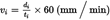
The highest burning rate of V1, V2 and V3 shall be taken into account.


(3)
Opinion of the European Parliament of 29 October 1992 (OJ No C 305, 23.11.1992, p. 109), Council common position of 8 December 1994 (OJ No C 384, 31.12.1994, p. 1) and Decision of the European Parliament of 15 June 1995 (OJ No C 166, 3.7.1995).
(4)
OJ No L 42, 23.2.1970, p. 1. Directive as last amended by Commission Directive 93/81/EEC (OJ No L 264, 23.10.1993, p. 49).
(5)
OJ No L 267, 19.10.1977, p. 1. Directive last amended by Commission Directive 90/630/EEC (OJ No L 341, 6.12.1990, p. 20).
(6)
The burning rate (B) for each sample is only calculated in the case where the flame reaches the last measuring point or the end of the sample.
Options/Help
Print Options
PrintThe Whole Directive
Legislation is available in different versions:
Latest Available (revised):The latest available updated version of the legislation incorporating changes made by subsequent legislation and applied by our editorial team. Changes we have not yet applied to the text, can be found in the ‘Changes to Legislation’ area.
Original (As adopted by EU): The original version of the legislation as it stood when it was first adopted in the EU. No changes have been applied to the text.
Point in Time: This becomes available after navigating to view revised legislation as it stood at a certain point in time via Advanced Features > Show Timeline of Changes or via a point in time advanced search.
See additional information alongside the content
Geographical Extent: Indicates the geographical area that this provision applies to. For further information see ‘Frequently Asked Questions’.
Show Timeline of Changes: See how this legislation has or could change over time. Turning this feature on will show extra navigation options to go to these specific points in time. Return to the latest available version by using the controls above in the What Version box.
Opening Options
Different options to open legislation in order to view more content on screen at once
More Resources
Access essential accompanying documents and information for this legislation item from this tab. Dependent on the legislation item being viewed this may include:
- the original print PDF of the as adopted version that was used for the EU Official Journal
- lists of changes made by and/or affecting this legislation item
- all formats of all associated documents
- correction slips
- links to related legislation and further information resources
Timeline of Changes
This timeline shows the different versions taken from EUR-Lex before exit day and during the implementation period as well as any subsequent versions created after the implementation period as a result of changes made by UK legislation.
The dates for the EU versions are taken from the document dates on EUR-Lex and may not always coincide with when the changes came into force for the document.
For any versions created after the implementation period as a result of changes made by UK legislation the date will coincide with the earliest date on which the change (e.g an insertion, a repeal or a substitution) that was applied came into force. For further information see our guide to revised legislation on Understanding Legislation.
More Resources
Use this menu to access essential accompanying documents and information for this legislation item. Dependent on the legislation item being viewed this may include:
- the original print PDF of the as adopted version that was used for the print copy
- correction slips
Click 'View More' or select 'More Resources' tab for additional information including:
- lists of changes made by and/or affecting this legislation item
- confers power and blanket amendment details
- all formats of all associated documents
- links to related legislation and further information resources
 All content is available under the Open Government Licence v3.0 except where otherwise stated. This site additionally contains content derived from EUR-Lex, reused under the terms of the Commission Decision 2011/833/EU on the reuse of documents from the EU institutions. For more information see the EUR-Lex public statement on re-use.