Appendix 1
[Type I test (for vehicles tested against the emission limits laid down in Row A of the Table in section 2.2.1.1.5 of this Annex)
(checking the average emission of pollutants)]
1.INTRODUCTIONU.K.
Procedure for Type I test specified in section 2.2.1.1 of Annex II.
1.1.The motorcycle or motor tricycle is placed on a dynamometer equipped with a brake and flywheel. A test lasting a total of 13 minutes and comprising four cycles is carried out without interruption. Each cycle comprises 15 operations (idling, acceleration, steady speed, deceleration, etc.). During the test the exhaust gases are diluted with air so that the flow volume of the mixture remains constant. Throughout the test a continous flow of samples of the mixture must be passed into a bag so that concentrations (average test values) of carbon monoxide, unburnt hydrocarbons, oxides of nitrogen and carbon dioxide can be determined in succession.U.K.
2.OPERATING CYCLE ON THE DYNAMOMETERU.K.
2.1.Description of cycleU.K.
The operating cycle on the dynamometer must be that indicated in the following table and plotted in Sub-appendix 1.
2.2.General conditions for carrying out the cycleU.K.
Preliminary test cycles must be carried out if necessary to determine how best to actuate the accelerator and brake controls so as to achieve a cycle approximating to the theoretical cycle within the prescribed limits.
2.3.Use of the gearboxU.K.
2.3.1.Use of the gearbox is determined as follows:U.K.
2.3.1.1.At constant speed, the engine speed must as far as possible remain between 50 % and 90 % of the maximum speed. If this speed can be achieved using more than one gear, the engine is tested using the highest gear.U.K.
2.3.1.2.During acceleration, the engine must be tested using the gear which allows maximum accleration. The next higher gear is engaged at the latest when the engine speed has reached 110 % of rated maximum output. If a motorcycle or motor tricycle reaches a speed of 20 km/h in first gear or 35 km/h in second gear, the next higher gear must be engaged at these speeds.U.K.
In these cases, no other change into higher gears is permitted. If, during the acceleration phase, the gears are changed at fixed motorcycle or motor tricycle speeds, the steady speed phase which follows must be performed with the gear which is engaged when the motorcycle or motor tricycle begins the steady speed phase, irrespective of the engine speed.
2.3.1.3.During deceleration, the next lower gear must be engaged before the engine reaches virtual idling speed and at the latest when the engine speed has fallen to 30 % of rated maximum output, whichever occurs earlier. First gear must not be engaged during deceleration.U.K.
2.3.2.Motorcycles or motor tricycles equipped with automatic gearboxes are tested with the highest gear engaged (‘drive’). The accelerator must be operated in such a way as to obtain as steady an acceleration as possible so that the transmission engages the different gears in the normal order. The tolerances specified in 2.4 apply.U.K.
2.4.TolerancesU.K.
2.4.1.A tolerance of ± 1 km/h above or below the theoretical speed is allowed during all phases. Speed tolerances greater than those prescribed are permitted during phase changes provided that the tolerances are never exceeded for more than 0,5 on any one occasion, in all cases subject to the provisions of 6.5.2 and 6.6.3.U.K.
2.4.2.A tolerance of ± 0,5 seconds above or below the theoretical times must be allowed.U.K.
2.4.3.The speed and time tolerances are combined as indicated in Sub-appendix 1.U.K.
2.4.4.The distance travelled during the cycle must be measured with a tolerance of ± 2 %.U.K.
Operating cycle on the dynamometerU.K.
| |
| No of ops | Operations | Phase | Acceleration(m/s2) | Speed(km/h) | Duration of each op. phase | Cum. time(sec) | Gear to be used in the case of a manual gearbox |
|---|
| (sec) | (sec) |
|---|
| 1 | Idling | 1 | | | 11 | 11 | 11 | 6 sec. PM/5 sec. K |
| 2 | Acceleration | 2 | 1,04 | 0—15 | 4 | 4 | 15 | See 2.3. |
| 3 | Steady speed | 3 | | 15 | 8 | 8 | 23 |
| 4 | Deceleration | 4 | -0,69 | 15—10 | 2 | 5 | 25 |
| 5 | Deceleration, clutch diseng. | - 0,92 | 10—0 | 3 | 28 | K |
| 6 | Idling | 5 | | | 21 | 21 | 49 | 16 sec. PM/5 sec. K |
| 7 | Acceleration | 6 | 0,74 | 0—32 | 12 | 12 | 61 | See 2.3. |
| 8 | Steady speed | 7 | | 32 | 24 | 24 | 85 |
| 9 | Deceleration | 8 | - 0,75 | 32—10 | 8 | 11 | 93 |
| 10 | Deceleration, clutch diseng. | - 0,92 | 10—0 | 3 | 96 | K |
| 11 | Idling | 9 | | | 21 | 21 | 117 | 16 sec. PM/5 sec. K |
| 12 | Acceleration | 10 | 0,53 | 0—50 | 26 | 26 | 143 | |
| 13 | Steady speed | 11 | | 50 | 12 | 12 | 155 | See 2.3. |
| 14 | Deceleration | 12 | - 0,52 | 50—35 | 8 | 8 | 163 |
| 15 | Steady speed | 13 | | 35 | 13 | 13 | 176 |
| 16 | Deceleration | 14 | - 0,68 | 35—10 | 9 | 12 | 185 | K |
| 17 | Deceleration, clutch diseng. | - 0,92 | 10—0 | 3 | 188 |
| 18 | Idling | 15 | | | 7 | 7 | 195 | 7 sec. PM |
3.MOTORCYCLE OR MOTOR TRICYCLE AND FUELU.K.
3.1.Test motorcycle or motor tricycleU.K.
3.1.1.The motorcycle or motor tricycle must be presented in good mechanical condition. It must have been run in and driven at least 1 000 km before the test. The laboratory may decide whether a motorcycle or motor tricycle which has travelled less than 1 000 km before the test may be accepted.U.K.
3.1.2.The exhaust device must not have any leaks likely to reduce the quantity of gases collected, which must equal the quantity of gases emerging from the engine.U.K.
[3.1.3. The tightness of the intake system may be checked to ensure the carburation is not affected by an accidental intake of air.] U.K.
3.1.4.The settings of the motorcycle or motor tricycle must be as prescribed by the manufacturer.U.K.
3.1.5.The laboratory may verify that the motorcycle or motor tricycle delivers the performance stated by the manufacturer, that it can be used for normal driving, and more particularly that it is capable of starting when cold and when hot.U.K.
3.2.FuelU.K.
The fuel used for the test must be the reference fuel as defined in Annex IV. If the engine is lubricated by a mixture, the oil added to the reference fuel must comply as to quality and quantity with the manufacturer's recommendations.
4.TEST EQUIPMENTU.K.
4.1.DynamometerU.K.
The main characteristics of the dynamometer are as follows:
Contact between roller and tyre of each driving wheel:
diameter of roller ≥ 400 mm;
Equation for power-absorption curve: from an initial speed of 12 km/h, the test bench must be able to reproduce, with a tolerance of ± 15 %, the power developed by the engine when the motorcycle or motor tricycle is travelling along a flat road with wind speed virtually zero. Either the power absorbed by the brakes and the internal friction of the bench must be calculated according to the provisions of section 11 of Sub-appendix 4 to Appendix 1, or the power absorbed by the brakes and the internal friction of the bench are:
K V3 ± 5 % of K V3 ± 5 % of PV50
Additional inertias: 10 kg and 10 kg().
4.1.1.The distance effectively travelled is measured using a revolution counter driven by the roller which drives the brake and the flywheels.U.K.
4.2.Equipment for sampling the gases and measuring their volumeU.K.
4.2.1.Sub-appendices 2 and 3 contain a diagram showing the principle for collecting, diluting, sampling and measuring the volume of exhaust gases during the test.U.K.
4.2.2.The following sections describe the components of the test equipment (against each component is given the abbreviation used in the sketch in Sub-appendices 2 and 3). The technical service may authorize the use of different equipment provided that it gives equivalent results:U.K.
4.2.2.1.a device to collect all the exhaust gases produced during the test; this is generally an open device, which maintains atmospheric pressure at the exhaust pipe(s). Nevertheless, a closed system may be used provided that the back-pressure conditions are complied with (with ± 1,25 kPa). The gases must be collected in such a way that there is not sufficient condensation to have a significant effect on the nature of the exhaust gases at the test temperature;U.K.
4.2.2.2.a tube (Tu) connecting the exhaust-gas collection equipment and the exhaust-gas sampling system. This connecting tube and the gas-collection equipment must be made of stainless steel, or of another material which will not affect the composition of the gases collected and will resist their temperature;U.K.
4.2.2.3.a heat exchanger (Sc) capable of limiting the variation in the temperature of the diluted gases at the pump inlet to within ± 5 oC for the duration of the test. This exchanger must be equipped with a pre-heating system capable of bringing the gases up to its operating temperature (with a tolerance of ± 5 oC) before the test commences;U.K.
4.2.2.4.a displacement pump (P1) to suck in the diluted gases driven by a motor which can operate at various rigorusly constant speeds. The pump must guarantee constant flow of a sufficient volume in order to ensure that all the exhaust gases are sucked in. A device which uses a critical float Venturi may also be used;U.K.
4.2.2.5.a device which can continually record the temperature of the diluted gases entering the pump;U.K.
4.2.2.6.a sampling probe (S3) attached to the outside of the gas-collection device which can collect a constant sample of the dilution air using a pump, a filter and a flow meter for the duration of the test;U.K.
4.2.2.7.a sampling probe S2, placed before the displacement pump and directed upstream of the flow of diluted gases to sample the mixture of diluted gases for the duration of the test at a constant rate of flow using, if necessary, a filter, a flow meter and a pump. The minimum rate of flow of the gases in the two sampling systems described above must be at least 150 l/h;U.K.
4.2.2.8.two filters (F2 and F3), placed after probes S2 and S3 respectively, designed to filter out the solid particles suspended in the flow of the sample collected in the bags. Particular care must be taken to ensure that they do not affect the concentrations of gaseous components in the samples;U.K.
4.2.2.9.two pumpes (P2 and P3) to take samples from probes S2 and S3 respectively and to fill bags Sa and Sb;U.K.
4.2.2.10.two hand-adjustable valves (V2 and V3) installed in series with pumps P2 and P3 respectively in order to regulate the flow of the sample sent into the bags;U.K.
4.2.2.11.two rotameters (R2 and R3) installed in series in the lines ‘probe, filter, pump, valve, bag’ (S2, F2, P2, V2, Sa and S3, F3, P3, V3 Sb respectively) so that instant visual checks can be made on the flow of the sample at any moment;U.K.
4.2.2.12.leak-tight sampling bags to collect the dilution air and mixture of diluted gases which are of sufficient capacity not to disrupt the normal flow of sampling. These sampling bags must have automatic sealing devices on the side of the bag which can be closed rapidly and tightly, either on the sampling circuit or on the analysis circuit at the end of the test;U.K.
4.2.2.13.two differential pressure manometers (g1 and g2) installed:U.K.
| g1: | before pump P1 in order to measure the difference in pressure between the mixture of exhaust gases and dilution air and the atmosphere; |
| g2: | before and after pump P1 in order to measure the increase in pressure exerted on the flow of gas; |
4.2.2.14.a revolution counter to count the number of revolutions made by the rotary displacement P1;U.K.
4.2.2.15.three-way valves on the sampling circuits described above to direct the flow of samples either to the atmosphere or to their respective sampling bags for the duration of the test. Rapid-action valves must be used. They must be manufactured from materials which do not affect the composition of the gases; they must also have discharge cross-sections and shapes which minimize load losses as far as technically possible.U.K.
4.3.Analytical equipmentU.K.
4.3.1.Measuring the concentration of hydrocarbonsU.K.
4.3.1.1.A flame-ionization analyser is used to measure the concentration of unburnt hydrocarbons in the samples collected in bags Sa and Sb, during the test.U.K.
4.3.2.Measuring the concentrations of CO and CO2 U.K.
4.3.2.1.A non-dispersive infra-red absorption analyser is used to measure the concentrations of carbon monoxide CO and carbon dioxide CO2 in the samples collected in bags Sa and Sb during the test.U.K.
4.3.3.Measuring the concentration of NOx U.K.
4.3.3.1.A chemiluminescent analyser is used to measure the concentrations of oxides of nitrogen (NOx) in the samples collected in bags Sa and Sb during the test.U.K.
4.4.Accuracy of instruments and measurementsU.K.
4.4.1.As the brake is calibrated in a separate test, it is not necessary to indicate the accuracy of the dynamometer. The total inertia of the rotating masses, including that of the rollers and the rotating part of the brake (see 5.2), must be given to within ± 2 %.U.K.
4.4.2.The speed of the motorcycle or motor tricycle is measured by the speed of rotation of the rollers connected to the brake and the flywheels. It must be measurable to within ± 2 km/h from 0 to 10 km/h and to within ± 1 km/h for speeds above 10 km/h.U.K.
4.4.3.The temperature referred to in 4.2.2.5 must be measurable to within ± 1 oC. The temperaure referred to in 6.1.1 must be measurable to within ± 2 oC.U.K.
4.4.4.The atmospheric pressure must be measurable to within ± 0,133 kPa.U.K.
4.4.5.The drop in pressure in the mixture of diluted gases entering pump P1 (see 4.2.2.13) compared with atmospheric pressure must be measurable to within ± 0,4 kPa. The difference in pressure of the diluted gases entering the sections before and after pump P1 (see 4.2.2.13) must be measurable to within ± 0,4 kPa.U.K.
4.4.6.The volume displaced at each complete rotation of pump P1 and the displacement value at the lowest possible pump speed, as recorded by the revolution counter, must make it possible to determine the overall volume of the mixture of exhaust gases and dilution air displaced by pump P1 during the test to within ± 2 %.U.K.
4.4.7.Irrespective of the accuracy with which the standard gases are determined, the measuring range of the analysers must be compatible with the accuracy required to measure the content of the various pollutants to within ± 3 %.U.K.
The flame-ionization analyser which measures the concentration of hydrocarbons must be capable of reaching 90 % of the full scale in less than one second.
4.4.8.The content of the standard (calibration) gases must not differ by more than ± 2 % from the reference value of each gas. The diluent must be nitrogen.U.K.
5.PREPARING THE TESTU.K.
5.1.Setting of brakeU.K.
5.1.1.The brake must be so adjusted that the speed of the motorcycle or motor tricycle during the steady speed phase is between 45 km/h and 55 km/h on a flat dry road.U.K.
5.1.2.The brake is adjusted as follows:U.K.
5.1.2.1.An adjustable stop to keep the maximum speed between 45 km/h and 55 km/h is fitted to the fuel supply device. The speed of the motorcycle or motor tricycle is measured by means of a precision tachometer or deduced from measuring the time over a given distance on a flat dry road in both directions with the stop closed.U.K.
The measurements must be repeated at least three times in both directions and must be made over a distance of at least 200 m with a sufficiently long acceleration distance. The average speed is calculated.
5.1.2.2.Other systems may also be used to measure the power required to propel the vehicle (e.g. measuring the torque on the transmission, measuring deceleration, etc.).U.K.
5.1.2.3.The motorcycle or motor tricycle must then be placed on the dynamometer and the brake adjusted so as to obtain the same speed as that attained in the road test (with the fuel-regulating device in the stop position and the same gear selected). This brake adjustment must be maintained throughout the test. Once the brake has been adjusted, the fuel-regulating device is removed.U.K.
5.1.2.4.Setting the brake on the basis of road tests is allowed only if the difference in barometric pressure between the road and the premises in which the dynamometer is housed, does not exceed ± 1,33 kPa and the difference in air temperature is not more than ± 8 oC.U.K.
5.1.3.If the above method is not applicable, the dynamometer must be set in accordance with the values in the table in 5.2. The table shows power values as a function of reference mass at a speed of 50 km/h. This power is determined using the method described in Sub-appendix 4.U.K.
5.2.Adjustment of equivalent inertias to the translatory inertias of the motorcycle or motor tricycle.U.K.
One or more flywheels are used enabling a total inertia of the rotating masses to be obtained proportional to the reference mass of the motorcycle or motor tricycle within the following limits:
| Reference mass (RM)(in kg) | Equivalent inertias(in kg) | Absorbed power(in kW) |
|---|
| RM ≤ 105 | 100 | 0,88 |
| 105 < RM ≤ 115 | 110 | 0,9 |
| 115 < RM ≤ 125 | 120 | 0,91 |
| 125 < RM ≤ 135 | 130 | 0,93 |
| 135 < RM ≤ 150 | 140 | 0,94 |
| 150 < RM ≤ 165 | 150 | 0,96 |
| 165 < RM ≤ 185 | 170 | 0,99 |
| 185 < RM ≤ 205 | 190 | 1,02 |
| 205 < RM ≤ 225 | 210 | 1,05 |
| 225 < RM ≤ 245 | 230 | 1,09 |
| 245 < RM ≤ 270 | 260 | 1,14 |
| 270 < RM ≤ 300 | 280 | 1,17 |
| 300 < RM ≤ 330 | 310 | 1,21 |
| 330 < RM ≤ 360 | 340 | 1,26 |
| 360 < RM ≤ 395 | 380 | 1,33 |
| 395 < RM ≤ 435 | 410 | 1,37 |
| 435 < RM ≤ 480 | 450 | 1,44 |
| 480 < RM ≤ 540 | 510 | 1,5 |
| 540 < RM ≤ 600 | 570 | 1,56 |
| 600 < RM ≤ 650 | 620 | 1,61 |
| 650 < RM ≤ 710 | 680 | 1,67 |
| 710 < RM ≤ 770 | 740 | 1,74 |
| 770 < RM ≤ 820 | 800 | 1,81 |
| 820 < RM ≤ 880 | 850 | 1,89 |
| 880 < RM ≤ 940 | 910 | 1,99 |
| 940 < RM ≤ 990 | 960 | 2,05 |
| 990 < RM ≤ 1 050 | 1020 | 2,11 |
| 1 050 < RM ≤ 1 110 | 1 080 | 2,18 |
| 1 110 < RM ≤ 1 160 | 1 130 | 2,24 |
| 1 160 < RM ≤ 1 220 | 1 190 | 2,3 |
| 1 220 < RM ≤ 1 280 | 1 250 | 2,37 |
| 1 280 < RM ≤ 1 330 | 1 300 | 2,42 |
| 1 330 < RM ≤ 1 390 | 1 360 | 2,49 |
| 1 390 < RM ≤ 1 450 | 1 420 | 2,54 |
| 1 450 < RM ≤ 1 500 | 1 470 | 2,57 |
| 1 500 < RM ≤ 1 560 | 1 530 | 2,62 |
| 1 560 < RM ≤ 1 620 | 1 590 | 2,67 |
| 1 620 < RM ≤ 1 670 | 1 640 | 2,72 |
| 1 670 < RM ≤ 1 730 | 1 700 | 2,77 |
| 1 730 < RM ≤ 1 790 | 1 760 | 2,83 |
| 1 790 < RM ≤ 1 870 | 1 810 | 2,88 |
| 1 870 < RM ≤ 1 980 | 1 930 | 2,97 |
| 1 980 < RM ≤ 2 100 | 2 040 | 3,06 |
| 2 100 < RM ≤ 2 210 | 2 150 | 3,13 |
| 2 210 < RM ≤ 2 320 | 2 270 | 3,2 |
| 2 320 < RM ≤ 2 440 | 2 380 | 3,34 |
| 2 440 < RM | 2 490 | 3,48 |
5.3.Conditioning of the motorcycle or motor tricycleU.K.
5.3.1.Before the test, the motorcycle or motor tricycle must be kept in a room in which the temperature remains relatively constant between 20 oC and 30 oC. This conditioning must be carried out until the engine oil temperature and coolant, if any, are within ± 2 K of the temperature of the room. [Two complete pre-conditioning cycles are performed before the exhaust gases are collected.] U.K.
5.3.2.The tyre pressure must be that indicated by the manufacturer for performance of the preliminary road test to set the brake. However, if the diameter of the rollers is less than 500 mm, the pressure in the tyres may be increased by 30 %-50 %.U.K.
5.3.3.The mass on the driven wheel is the same as when the motorcycle or motor tricycle is used under normal driving conditions with a driver weighing 75 kg.U.K.
5.4.Calibration of analytical apparatusU.K.
5.4.1.Calibration of analysersU.K.
The quantity of gas at the indicated pressure compatible with the correct functioning of the equipment is injected into the analyser by means of the flow meter and discharge gauge mounted on each bottle. The apparatus is adjusted to indicate as a stabilized value, the value shown on the standard gas bottle. Starting from the setting obtained with the maximum-content bottle, the curve of the analyser's deviations is drawn as a function of the content of the various standard gas bottles used. For the regular calibration of flame-ionization analysers, which should be done at least once a month, mixtures of air and propane (or hexane) with rated concentrations of hydrocarbon equal to 50 % and 90 % of the full scale are used. For regular calibration of non-dispersive infra-red absorption analysers, mixtures of nitrogen with CO and CO2 respectively are measured at rated concentrations of 10 %, 40 %, 60 %, 85 % and 90 % of the full scale. For calibration of the chemiluminescent NOx analyser, mixtures of nitrous oxide (N2O) diluted in nitrogen with a nominal concentration of 50 % and 90 % of the full scale are used. For the test calibration, which must be carried out before each series of tests, it is necessary, for all three types of analyser, to use mixtures containing the gases to be measured to a concentration equal to 80 % of the full scale. A dilution device can be used for diluting a 100 % calibration gas to the required concentration.
6.PROCEDURE FOR DYNAMOMETER TESTSU.K.
6.1.Special conditions for carrying out the cycleU.K.
6.1.1.The temperature in the premises where the dynamometer bench is situated must be between 20 o and 30 oC throughout the test, and must be as close as possible to the temperature of the premises where the motorcycle or motor tricycle were conditioned.U.K.
6.1.2.The motorcycle or motor tricycle must as far as possible be horizontal during the test so as to avoid any abnormal distribution of the fuel.U.K.
[6.1.3. Before initiation of the first pre-conditioning cycle, a flow of air of variable speed is directed at the motorcycle or motor tricycle. Two complete cycles are then performed during which no exhaust gases are collected. The ventilation system must include a mechanism controlled by the speed of the bench roller so that, in the range from 10 km/h to 50 km/h, the linear air speed at the blower outlet is equal to the relative speed of the roller with an approximation of 10 %. For roller speeds below 10 km/h, the air speed may be zero. The end section of the blower device must have the following characteristics: U.K.
(i)
surface area of at least 0,4 m 2 ;
(ii)
lower edge between 0,15 and 0,20 m above ground level;
(iii)
distance from the leading edge of the motorcycle or motor tricycle between 0,3 and 0,45 m.]
6.1.4.During the test, speed is plotted against time in order to check that the cycles have been performed correctly.U.K.
6.1.5.The temperatures of the cooling water and the crankcase oil may be recorded.U.K.
6.2.Starting up the engineU.K.
6.2.1.Once the preliminary operations on the equipment for collecting, diluting, analysing and measuring the gases have been carried out (see 7.1), the engine is started up by means of the devices provided for that purpose, such as the choke, the starter valve, etc., according to the manufacturer's instructions.U.K.
[6.2.2. The first cycle begins when the taking of samples and the measuring of the pump rotations commence.] U.K.
6.3.Use of the manual chokeU.K.
The choke must be cut out as soon as possible and in principle before acceleration from 0 to 50 km/h. If this requirement cannot be met, the moment of actual cut-out must be indicated. The choke must be adjusted in accordance with the manufacturer's instructions.
6.4.IdlingU.K.
6.4.1.Manual-shift gearbox:U.K.
6.4.1.1.During periods of idling the clutch must be engaged and the gears in neutral.U.K.
6.4.1.2.To enable the accelerations to be performed according to the normal cycle the vehicle must be put in first gear, with the clutch disengaged, five seconds before commencement of the acceleration following the idling period in question.U.K.
6.4.1.3.The first idling period at the beginning of the cycle consists of six seconds of idling in neutral with the clutch engaged and five seconds in first gear with the clutch disengaged.U.K.
6.4.1.4.For the idling periods during each cycle the corresponding times are 16 seconds in neutral and five seconds in first gear with the clutch disengaged.U.K.
6.4.1.5.The last idling period in the cycle consists of seven seconds in neutral with the clutch engaged.U.K.
6.4.2.Semi-automatic gearboxes:U.K.
the manufacturer's instructions for driving in town, or in their absence instructions applicable to manual gearboxes, must be followed.
6.4.3.Automatic gearboxes:U.K.
the selector must not be operated at any time during the test unless the manufacturer specifies otherwise. In the latter case the procedure for manual gearboxes applies.
6.5.AccelerationsU.K.
6.5.1.Accelerations must be effected so as to ensure that the rate of acceleration is as constant as possible throughout the operation.U.K.
6.5.2.If the acceleration capacities of the motorcycle or motor tricycle are not sufficient to perform the acceleration cycles within the prescribed tolerances, the motorcycle or motor tricycle must be driven with the throttle completely open until the speed prescribed for the cycle has been reached; the cycle may then continue normally.U.K.
6.6.DecelerationsU.K.
6.6.1.All decelerations must be effected by completely closing the throttle, the clutch remaining engaged. The engine must be disengaged at a speed of 10 km/h.U.K.
6.6.2.If the period of deceleration is longer than that prescribed for the corresponding phase, the vehicle's brakes are used to keep to the cycle.U.K.
6.6.3.If the period of deceleration is shorter than that prescribed for the corresponding phase, the timing of the theoretical cycle is restored by a steady-state or an idling period merging into the following steady-state or idling operation. In this case, section 2.4.3 is not applicable.U.K.
6.6.4.At the end of the deceleration period (stopping motorcycle or motor tricycle on the rollers) the gear is put into neutral and the clutch engaged.U.K.
6.7.Steady speedsU.K.
6.7.1.‘Pumping’ or the closing of the throttle must be avoided when passing from acceleration to the following steady speed.U.K.
6.7.2.Periods of constant speed must be achieved by keeping the accelerator position fixed.U.K.
7.PROCEDURE FOR SAMPLING, ANALYSING AND MEASURING THE VOLUME OF EMISSIONSU.K.
7.1.Operations to be carried out before the motorcycle or motor tricycle is started up.U.K.
7.1.1.The bags for collecting the samples. Sam and Sb, are emptied and sealed.U.K.
7.1.2.The rotary displacement pump P1 is activated without starting up the revolution counter.U.K.
7.1.3.The pumpes P2 and P3 for taking the samples are activated with the valves set to divert the gases produced into the atmosphere; the flow through valves V2 and V3 is regulated.U.K.
7.1.4.The recording devices for the temperature T and the pressure g1 and g2 are put into operation.U.K.
7.1.5.The revolution counter CT and the roller revolution counter are set to zero.U.K.
7.2.Beginning of sampling and volume measurement.U.K.
[7.2.1. After two pre-conditioning cycles (first moment of the first cycle), the operations specified in 7.2.2 to 7.2.5 are performed simultaneously.] U.K.
7.2.2.The diversion valves are set to collect the samples, which have previously been directed towards the atmosphere, continuously through probes S2 and S3 in bags Sa and Sb.U.K.
7.2.3.The moment at which the test begins is indicated on the analogue graphs which record results from the temperature gauge T and the differential pressure gauges g1 and g2.U.K.
7.2.4.The counter which records the total number of revolutions of pump P1 is started up.U.K.
7.2.5.The device referred to in 6.1.3 which directs a flow of air at the motorcycle or motor tricycle is started up.U.K.
7.3.End of sampling and measurement of volumeU.K.
7.3.1.At the end of the fourth test cycle the operations described in 7.3.2 to 7.3.5 are performed simultaneously.U.K.
7.3.2.The diversion valves must be set to close bags Sa and Sb and to discharge into the atmosphere the samples sucked in by pumps P2 and P3 through probes S2 and S3.U.K.
7.3.3.The moment at which the test finishes must be indicated on the analogue graphs referred to in 7.2.3.U.K.
7.3.4.The pump P1 revolution counter is stopped.U.K.
7.3.5.The device referred to in 6.1.3 which directs a flow of air at the motorcycle or motor tricycle is stopped.U.K.
[7.4. Analysis U.K.
7.4.1. The exhaust gases contained in the bag must be analysed as soon as possible and in any event not later than 20 minutes after the end of the test cycle. U.K.
7.4.2. Prior to each sample analysis the analyser range to be used for each pollutant must be set to zero with the appropriate zero gas. U.K.
7.4.3. The analysers are then set to the calibration curves by means of span gases of nominal concentrations of 70 to 100 % of the range. U.K.
7.4.4. The analysers' zeros are then rechecked. If the reading differs by more than 2 % of range from that set in 7.4.2, the procedure is repeated. U.K.
7.4.5. The samples are then analysed. U.K.
7.4.6. After the analysis, zero and span points are rechecked using the same gases. If these rechecks are within 2 % of those in 7.4.3, the analysis is considered acceptable. U.K.
7.4.7. At all points in this Section the flow-rates and pressures of the various gases must be the same as those used during calibration of the analysers. U.K.
7.4.8. The figure adopted for the concentration of each pollutant measured in the gases is that read off after stabilisation on the measuring device.] U.K.
7.5.Measuring the distance travelledU.K.
The distance S actually travelled, expressed in km, is obtained by multiplying the total number of revolutions shown on the revolution counter by the size of the roller (see 4.1.1).
8.DETERMINATION OF THE QUANTITY OF GASEOUS POLLUTANTS EMITTEDU.K.
8.1.The mass of carbon monoxide gas emitted during the test is determined by means of the formula:U.K.
where:
8.1.1.COM is the mass of carbon monoxide emitted during the test, expressed in g/km.U.K.
8.1.2.S is the distance defined 7.5;U.K.
8.1.3.dCO is the density of carbon monoxide at a temperature of 0 oC and at a pressure of 101,33 kPa (= 1,250 kg/m3);U.K.
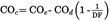
8.1.4.COc is the volume concentration of carbon monoxide in the diluted gases, expressed in parts per million and corrected to take account of pollution of the dilution air:U.K.
where:
8.1.4.1.COe is the concentration of carbon monoxide, measured in parts per million, in the sample of diluted gases collected in bag Sb;U.K.
8.1.4.2.COd is the concentration of carbon monoxide, measured in parts per million, in the sample of dilution air collected in bag Sa;U.K.
8.1.4.3.DF is the coefficient specified in 8.4.U.K.
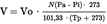
8.1.5.V is the total volume, expressed in m3/test, of diluted gases at reference temperature 0 oC (273 oK) and reference pressure 101,33 kPa,U.K.
where:
8.1.5.1.Vo is the volume of gas displaced by pump P1 during one rotation expressed in m3/revolution. This volume is a function of the differential pressures between the inlet and outlet sections of the group itself.U.K.
8.1.5.2.N is the number of rotations made by the pump P1 during the four test cycles.U.K.
8.1.5.3.Pa is the atmospheric pressure expressed in kPa;U.K.
8.1.5.4.Pi is the mean value, expressed in kPa, during performance of the four cycles of the drop in pressure in the inlet section of pump P1;U.K.
8.1.5.5.Tp is the value, during performance of the four cycles, of the temperature of the diluted gases measured in the inlet section of pump P1.U.K.
8.2.The mass of unburnt hydrocarbons emitted through the exhaust of the motorcycle or motor tricycle during the test is calculated by means of the formula:U.K.
where:
8.2.1.HCM is the mass of hydrocarbons emitted during the test, expressed in g/km;U.K.
8.2.2.S is the distance defined in 7.5;U.K.
8.2.3.dHC is the density of hydrocarbons at a temperature of 0 oC and a pressure of 101,33 kPa for an average ratio of carbon to hydrogen of 1:1,85 (= 0,619 kg/m3);U.K.
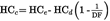
8.2.4.HCc is the concentration of the diluted gases expressed in parts per million carbon equivalent (for example: the concentration of propane multiplied by 3) and corrected to take account of the dilution air:U.K.
where:
8.2.4.1.HCe is the concentration of hydrocarbons, expressed in parts per million carbon equivalent, in the sample of diluted gases collected in bag Sb;U.K.
8.2.4.2.HCd is the concentration of hydrocarbons, expressed in parts per million carbon equivalent, in the sample of dilution air collected in bag Sa;U.K.
8.2.4.3.DF is the coefficient specified in 8.4;U.K.
8.2.5.V is the total volume (see 8.1.5).U.K.
8.3.The mass of oxides of nitrogen emitted through the exhaust of the motorcycle or motor tricycle during the test is calculated by means of the formula:U.K.
where:
8.3.1.NOxM is the mass of oxides of nitrogen emitted during the test, expressed in g/km;U.K.
8.3.2.S is the distance defined in 7.5;U.K.
8.3.3.dNO2 is the density of the oxides of nitrogen in the exhaust gases, in NO2 equivalent, at a temperature of 0 oC and a pressure of 101,33 kPa (= 2,05 kg/m3);U.K.
8.3.4.NOxc is the concentration of oxides of nitrogen in the diluted gases, expressed in parts per million and corrected to take account of the dilution air:U.K.
where:
8.3.4.1.NOxe is the concentration of oxides of nitrogen, expressed in parts per million, in the sample of diluted gases collected in bag Sa;U.K.
8.3.4.2.NOxd is the concentration of oxides of nitrogen, expressed in parts per million, in the sample of dilution air collected in bag Sb;U.K.
8.3.4.3.DF is the coefficient specified 8.4;U.K.
8.3.5.Kh is the correction factor for humidity:U.K.
where:
8.3.5.1.H is the absolute humidity in grams of water per kg of dry air:U.K.
where:
8.3.5.1.1.U is the humidity content expressed as a percentage;U.K.
8.3.5.1.2.Pd is the saturated-water-vapour pressure, expressed in kPa, at the test temperature;U.K.
8.3.5.1.3.Pa is the atmospheric pressure in kPa;U.K.
8.4.DF is a coefficient expressed by means of the formula:U.K.
where:
8.4.1.CO, CO2 and HC are concentrations of carbon monoxide, carbon dioxide and hydrocarbons expressed as a percentage of the sample of diluted gases contained in bag Sa.U.K.
Sub-appendix 1
Engine operating cycle for the Type I test
Sub-appendix 2
Example No 1 of an exhaust-gas collection system
Sub-appendix 3
Example No 2 of an exhaust-gas collection system
Sub-appendix 4
Method of calibrating the on-road power absorption by the dynamometer in the case of motorcycles or motor tricycles
This Sub-appendix describes a method used to determine on-road power absorption using a dynamometer.
The absorbed power measured on the road includes the power absorbed by friction and the power absorbed by the power absorption device. The dynamometer is operated above the range of test speeds. The device used to activate the dynamometer is then disconnected from the bench and the rotational speed of the roller(s) decreases.
The kinetic energy of the device is dissipated by the dynamometer power absorption unit and by the friction of the dynamometer. This method takes no account of variations in internal friction within the roller due to the rotating mass of the motorcycle or motor tricycle. The difference between the time the free rear-roller stops and the time the motor-driven front roller stops can be ignored in the case of a dynamometer with two rollers.
Procedures are as follows:
1.
The rotational speed of the roller is measured if this has not already been done. An additional measuring wheel, a revolution counter, or another method may be used.
2.
The motorcycle or motor tricycle is placed on the dynamometer or another method is used to make the dynamometer function.
3.
The flywheel, or any other of the inertia simulation systems most commonly used with the dynamometer for the particular category of motorcycle or motor tricycle mass, is engaged.
4.
The dynamometer is brought to a speed of 50 km/h.
5.
The power absorbed is recorded.
6.
The dynamometer is brought to a speed of 60 km/h.
7.
The device used to activate the dynamometer is disconnected.
8.
The time taken for the dynamometer to decrease from a speed of 55 km/h to a speed of 45 km/h is recorded.
9.
The power absorption device is set to a different level.
10.
Stages 4 to 9 above are repeated as often as required to cover the range of the on-road powers used.
11.
The absorbed power is calculated by means of the formula:
where:
M1
=
equivalent inertia in kg
V1
=
initial velocity in m/s (55 km/h = 15,28 m/s)
V2
=
final velocity in m/s (45 km/h = 12,50 m/s)
t
=
time taken by the roller to decelerate from 55 km/h to 45 km/h
12.
Diagram showing the power absorbed by the dynamometer according to the power indicated for the test speed of 50 km/h referred to in phase 4 below.

[Appendix 1a
Type I test (for vehicles tested against the emission limits laid down in Row B of the Table in section 2.2.1.1.5 of this Annex)
(checking the average emission of pollutants)
1. INTRODUCTION U.K.
Procedure for Type I test specified in section 2.2.1.1 of Annex II.
1.1. The motorcycle or motor tricycle is placed on a dynamometer equipped with a brake and flywheel. A test conducted over six elementary urban cycles lasting a total of 1 170 seconds for class I motorcycles or a test conducted over six elementary urban cycles plus one extra-urban cycle lasting a total of 1 570 seconds for class II motorcycles is carried out without interruption. U.K.
During the test the exhaust gases are diluted with air so that the flow volume of the mixture remains constant. Throughout the test a continuous flow of samples of the mixture must be passed into one or more bags so that concentrations (average test values) of carbon monoxide, unburnt hydrocarbons, oxides of nitrogen and carbon dioxide can be determined in succession.
2. OPERATING CYCLE ON THE DYNAMOMETER U.K.
2.1. Description of cycle U.K.
The operating cycles on the dynamometer are indicated in sub-Appendix 1.
2.2. General conditions for carrying out the cycle U.K.
Preliminary test cycles must be carried out if necessary to determine how best to actuate the accelerator and brake controls so as to achieve a cycle approximating to the theoretical cycle within the prescribed limits.
2.3. Use of the gearbox U.K.
2.3.1. Use of the gearbox is determined as follows: U.K.
2.3.1.1.
At constant speed, the engine speed must as far as possible remain between 50 % and 90 % of the maximum speed. If this speed can be achieved using more than one gear, the engine is tested using the highest gear.
2.3.1.2.
With respect to the urban cycle, during acceleration the engine must be tested using the gear which allows maximum acceleration. The next higher gear is engaged, at the latest, when the engine speed has reached 110 % of the speed at which the maximum rated power output occurs. If a motorcycle or motor tricycle reaches a speed of 20 km/h in first gear or 35 km/h in second gear, the next higher gear must be engaged at these speeds.
In these cases, no other change into higher gears is permitted. If, during the acceleration phase, the gears are changed at fixed motorcycle or motor tricycle speeds, the steady speed phase which follows must be performed with the gear which is engaged when the motorcycle or motor tricycle begins the steady speed phase, irrespective of the engine speed.
2.3.1.3.
During deceleration, the next lower gear must be engaged before the engine reaches virtual idling speed or when the engine speed has fallen to 30 % of the speed of the maximum rated output, whichever occurs first. First gear must not be engaged during deceleration.
2.3.2. Motorcycles or motor tricycles equipped with automatic gearboxes are tested with the highest gear engaged (drive). The accelerator must be operated in such a way as to obtain as steady an acceleration as possible so that the transmission engages the different gears in the normal order. The tolerances specified in section 2.4 apply. U.K.
2.3.3. For carrying out the extra-urban cycle, the gearbox shall be used according to the manufacturer's recommendations. U.K.
The gear change points shown in Appendix 1 to this Annex do not apply; acceleration must continue throughout the period represented by the straight line connecting the end of each period of idling with the beginning of the next following period of steady speed. The tolerances given in section 2.4 apply.
2.4. Tolerances U.K.
2.4.1. The theoretical speed shall be maintained to a tolerance of ± 2 km/h during all phases. Speed tolerances greater than those prescribed are permitted during phase changes provided that the tolerances are never exceeded for more than 0,5 seconds on any one occasion, in all cases subject to the provisions of sections 6.5.2 and 6.6.3. U.K.
2.4.2. A tolerance of ± 0,5 seconds above or below the theoretical times must be allowed. U.K.
2.4.3. The speed and time tolerances are combined as indicated in sub-Appendix 1. U.K.
2.4.4. The distance travelled during the cycle must be measured with a tolerance of ± 2 %. U.K.
3. MOTORCYCLE OR MOTOR TRICYCLE AND FUEL U.K.
3.1. Test motorcycle or motor tricycle U.K.
3.1.1. The motorcycle or motor tricycle must be presented in good mechanical condition. It should have been run in and driven at least 1 000 km before the test. The laboratory may decide whether a motorcycle or motor tricycle which has travelled less than 1 000 km before the test may be accepted. U.K.
3.1.2. The exhaust device must not have any leaks likely to reduce the quantity of gases collected, which must equal the quantity of gases emerging from the engine. U.K.
3.1.3. The tightness of the intake system may be checked to ensure the carburation is not affected by an accidental intake of air. U.K.
3.1.4. The settings of the motorcycle or motor tricycle must be as prescribed by the manufacturer. U.K.
3.1.5. The laboratory may verify that the motorcycle or motor tricycle delivers the performance stated by the manufacturer, that it can be used for normal driving, and more particularly that it is capable of starting when cold and when hot. U.K.
3.2. Fuel U.K.
The fuel used for the test must be the reference fuel as defined in Annex IV. If the engine is lubricated by a mixture, the oil added to the reference fuel must comply as to quality and quantity with the manufacturer's recommendations.
4. TEST EQUIPMENT U.K.
4.1. Dynamometer U.K.
The main characteristics of the dynamometer are as follows:
4.1.1. The distance effectively travelled is measured using a revolution counter driven by the roller which drives the brake and the flywheels. U.K.
4.2. Equipment for sampling the gases and measuring their volume U.K.
4.2.1. Sub-Appendices 2 and 3 of Appendix 1 contain a diagram showing the principle for collecting, diluting, sampling and measuring the volume of exhaust gases during the test. U.K.
4.2.2. The following sections describe the components of the test equipment (against each component is given the abbreviation used in the sketch in sub-Appendices 2 and 3 of Appendix 1). The technical service may authorise the use of different equipment provided that it gives equivalent results: U.K.
4.2.2.1. a device to collect all the exhaust gases produced during the test; this is generally an open device, which maintains atmospheric pressure at the exhaust pipe(s). Nevertheless, a closed system may be used provided that the back-pressure conditions are complied with (± 1,25 kPa). The gases must be collected in such a way that there is not sufficient condensation to have a significant effect on the nature of the exhaust gases at the test temperature; U.K.
4.2.2.2. a tube (Tu) connecting the exhaust-gas collection equipment and the exhaust-gas sampling system. This connecting tube and the gas-collection equipment must be made of stainless steel, or of another material which will not affect the composition of the gases collected and will resist their temperature; U.K.
4.2.2.3. a heat exchanger (S c ) capable of limiting the variation in the temperature of the diluted gases at the pump inlet to within ± 5 o C for the duration of the test. This exchanger must be equipped with a pre-heating system capable of bringing the gases up to operating temperature (± 5 o C) before the test commences; U.K.
4.2.2.4. a displacement pump (P 1 ) to suck in the diluted gases driven by a motor which can operate at various rigorously constant speeds. The pump must guarantee constant flow of a sufficient volume in order to ensure that all the exhaust gases are sucked in. A device which uses a critical flow venturi may also be used; U.K.
4.2.2.5. a device which can continually record the temperature of the diluted gases entering the pump; U.K.
4.2.2.6. a sampling probe (S 3 ) attached to the outside of the gas-collection device which can collect a constant sample of the dilution air using a pump, a filter and a flow meter for the duration of the test; U.K.
4.2.2.7. a sampling probe S 2 , placed before the displacement pump and directed upstream of the flow of diluted gases to sample the mixture of diluted gases for the duration of the test at a constant rate of flow using, if necessary, a filter, a flow meter and a pump. The minimum rate of flow of the gases in the two sampling systems described above must be at least 150 l/h; U.K.
4.2.2.8. two filters (F 2 and F 3 ), placed after probes S 2 and S 3 respectively, designed to filter out the solid particles suspended in the flow of the sample collected in the bags. Particular care must be taken to ensure that they do not affect the concentrations of gaseous components in the samples; U.K.
4.2.2.9. two pumps (P 2 and P 3 ) to take samples from probes S 2 and S 3 respectively and to fill bags S a and S b ; U.K.
4.2.2.10. two hand-adjustable valves (V 2 and V 3 ) installed in series with pumps P 2 and P 3 respectively in order to regulate the flow of the sample sent into the bags; U.K.
4.2.2.11. two rotameters (R 2 and R 3 ) installed in series in the lines ‘probe, filter, pump, valve, bag’ (S 2 , F 2 , P 2 , V 2 , S a and S 3 , F 3 , P 3 , V 3 , S b respectively) so that instant visual checks can be made on the flow of the sample at any moment; U.K.
4.2.2.12. leak-tight sampling bags to collect the dilution air and mixture of diluted gases which are of sufficient capacity not to disrupt the normal flow of sampling. These sampling bags must have automatic sealing devices on the side of the bag which can be closed rapidly and tightly, either on the sampling circuit or on the analysis circuit at the end of the test; U.K.
4.2.2.13. two differential pressure manometers (g U.K.
1 U.K.
and g U.K.
2 U.K.
) installed: U.K.
g 1
:
before pump P 1 in order to measure the difference in pressure between the mixture of exhaust gases and dilution air and the atmosphere;
g 2
:
before and after pump P 1 in order to measure the increase in pressure exerted on the flow of gas;
4.2.2.14. a revolution counter to count the number of revolutions made by the rotary displacement pump P 1 ; U.K.
4.2.2.15. three-way valves on the sampling circuits described above to direct the flow of samples either to the atmosphere or to their respective sampling bags for the duration of the test. Rapid-action valves must be used. They must be manufactured from materials which do not affect the composition of the gases; they must also have discharge cross-sections and shapes which minimise load losses as far as technically possible. U.K.
4.3. Analytical equipment U.K.
4.3.1. Measuring the concentration of hydrocarbons U.K.
4.3.1.1. A flame-ionisation analyser is used to measure the concentration of unburnt hydrocarbons in the samples collected in bags S a and S b , during the test. U.K.
4.3.2. Measuring the concentrations of CO and CO 2 U.K.
4.3.2.1. A non-dispersive infra-red absorption analyser is used to measure the concentrations of carbon monoxide CO and carbon dioxide CO 2 in the samples collected in bags S a and S b during the test. U.K.
4.3.3. Measuring the concentration of NO x U.K.
4.3.3.1. A chemiluminescent analyser is used to measure the concentrations of oxides of nitrogen (NO x ) in the samples collected in bags S a and S b during the test. U.K.
4.4. Accuracy of instruments and measurements U.K.
4.4.1. As the brake is calibrated in a separate test, it is not necessary to indicate the accuracy of the dynamometer. The total inertia of the rotating masses, including that of the rollers and the rotating part of the brake (see section 5.2), must be given to within ± 2 %. U.K.
4.4.2. The speed of the motorcycle or motor tricycle is measured by the speed of rotation of the rollers connected to the brake and the flywheels. It must be measurable to within ± 2 km/h from 0 to 10 km/h and to within ± 1 km/h for speeds above 10 km/h. U.K.
4.4.3. The temperature referred to in section 4.2.2.5 must be measurable to within ± 1 o C. The temperature referred to in section 6.1.1 must be measurable to within ± 2 o C. U.K.
4.4.4. The atmospheric pressure must be measurable to within ± 0,133 kPa. U.K.
4.4.5. The drop in pressure in the mixture of diluted gases entering pump P 1 (see section 4.2.2.13) compared with atmospheric pressure must be measurable to within ± 0,4 kPa. The difference in pressure of the diluted gases entering the sections before and after pump P 1 (see section 4.2.2.13) must be measurable to within ± 0,4 kPa. U.K.
4.4.6. The volume displaced at each complete rotation of pump P 1 and the displacement value at the lowest possible pump speed, as recorded by the revolution counter, must make it possible to determine the overall volume of the mixture of exhaust gases and dilution air displaced by pump P 1 during the test to within ± 2 %. U.K.
4.4.7. Irrespective of the accuracy with which the standard gases are determined, the measuring range of the analysers must be compatible with the accuracy required to measure the content of the various pollutants to within ± 3 %. U.K.
The flame-ionisation analyser which measures the concentration of hydrocarbons must be capable of reaching 90 % of the full scale in less than one second.
4.4.8. The content of the standard (calibration) gases must not differ by more than ± 2 % from the reference value of each gas. The diluent must be nitrogen. U.K.
5. PREPARING THE TEST U.K.
5.1. Road test U.K.
5.1.1. Requirement for road U.K.
The test road shall be flat, level, straight and smoothly paved. The road surface shall be dry and free of obstacles or wind barriers that might impede the measurement of the running resistance. The slope shall not exceed 0,5 % between any two points at least 2 m apart.
5.1.2. Ambient conditions for road test U.K.
During data collecting periods, the wind shall be steady. The wind speed and the direction of the wind shall be measured continuously or with adequate frequency at a location where the wind force during coastdown is representative.
The ambient conditions shall be within the following limits:
maximum wind speed: 3 m/s
maximum wind speed for gusts: 5 m/s
average wind speed, parallel: 3 m/s
average wind speed, perpendicular: 2 m/s
maximum relative humidity: 95 %
air temperature: 278 K to 308 K
Standard ambient conditions shall be as follows:
pressure, p 0 : 100 kPa
temperature, T 0 : 293 K
relative air density, d 0 : 0,9197
wind speed: no wind
air volumetric mass, ρ 0 : 1,189 kg/m 3
The relative air density when the motorcycle is tested, calculated in accordance with the formula below, shall not differ by more than 7,5 % from the air density under the standard conditions.
The relative air density, d T , shall be calculated by the formula:

where
d T
=
relative air density under test conditions;
p T
=
ambient pressure under test conditions, in kilopascals;
T T
=
absolute temperature during the test, in Kelvin.
5.1.3. Reference speed U.K.
The reference speed or speeds shall be as defined in the test cycle.
5.1.4. Specified speed U.K.
The specified speed, v, is required to prepare the running resistance curve. To determine the running resistance as a function of motorcycle speed in the vicinity of the reference speed v 0 , running resistances shall be measured using at least four specified speeds, including the reference speed(s). The range of specified speed points (the interval between the maximum and minimum points) shall extend either side of the reference speed or the reference speed range, if there is more than one reference speed, by at least Δv, as defined in 5.1.6. The specified speed points, including the reference speed point(s), shall be no greater than 20 km/h apart and the interval of specified speeds should be the same. From the running resistance curve the running resistance at the reference speed(s) can be calculated.
5.1.5. Coastdown starting speed U.K.
The coastdown starting speed shall be more than 5 km/h above the highest speed at which coastdown time measurement begins; since sufficient time is required, for example, to settle the positions of both the motorcycle and rider and to cut the transmitted engine power off before the speed is reduced to v 1 , the speed at which the measurement of the coastdown time is started.
5.1.6. Coastdown time measurement beginning speed and ending speed U.K.
To ensure accuracy in measuring the coastdown time Δt, and coastdown speed interval 2Δv, the beginning speed v 1 , and ending speed v 2 , in kilometres per hour, the following requirements shall be met:


Δv = 5 km/h for v < 60 km/h
Δv = 10 km/h for v ≥ 60 km/h
5.1.7. Preparation of test motorcycle U.K.
5.1.7.1. The motorcycle shall conform in all its components with the production series, or, if the motorcycle is different from the production series, a full description shall be given in the test report. U.K.
5.1.7.2. The engine, transmission and motorcycle shall be properly run in, in accordance with the manufacturer's requirements. U.K.
5.1.7.3. Motorcycle shall be adjusted in accordance with the manufacturer's requirements, e.g. the viscosity of the oils, tyre pressures, or, if the motorcycle is different from the production series, a full description shall be given in the test report. U.K.
5.1.7.4. The mass in running order of the motorcycle shall be as defined in section 1.2 of this Annex. U.K.
5.1.7.5. The total test mass including the masses of the rider and the instruments shall be measured before the beginning of the test. U.K.
5.1.7.6. The distribution of the load between the wheels shall be in conformity with the manufacturer's instructions. U.K.
5.1.7.7. When installing the measuring instruments on the test motorcycle, care shall be taken to minimise their effects on the distribution of the load between the wheels. When installing the speed sensor outside the motorcycle, care shall be taken to minimise the additional aerodynamic loss. U.K.
5.1.8. Rider and riding position U.K.
5.1.8.1. The rider shall wear a well-fitting suit (one-piece) or similar clothing, a protective helmet, eye protection, boots and gloves. U.K.
5.1.8.2. The rider in the conditions given in 5.1.8.1 shall have a mass of 75 kg ± 5 kg and be 1,75 m ± 0,05 m tall. U.K.
5.1.8.3. The rider shall be seated on the seat provided, with his feet on the footrests and his arms normally extended. This position shall allow the rider at all times to have proper control of the motorcycle during the coastdown test. U.K.
The position of the rider shall remain unchanged during the whole measurement.
5.1.9. Measurement of coastdown time U.K.
5.1.9.1. After a warm-up period, the motorcycle shall be accelerated to the coastdown starting speed, at which point the coastdown shall be started. U.K.
5.1.9.2. Since it can be dangerous and difficult from the viewpoint of its construction to have the transmission shifted to neutral, the coasting may be performed solely with the clutch disengaged. Further, the tractive method of using another motorcycle for traction shall be applied to those motorcycles that have no way of cutting the transmitted engine power off during coasting. When the coastdown test is reproduced on the chassis dynamometer, the transmission and clutch shall be in the same condition on the road test. U.K.
5.1.9.3. The motorcycle steering shall be altered as little as possible and the brakes shall not be operated until the end of the coastdown measurement. U.K.
5.1.9.4. The coastdown time Δt ai corresponding to the specified speed v j shall be measured as the elapsed time from the motorcycle speed v j +Δv to v j -Δv. U.K.
5.1.9.5. The procedure from 5.1.9.1 to 5.1.9.4 shall be repeated in the opposite direction to measure the coastdown time Δt bi . U.K.
5.1.9.6. The average ΔT i of the two coastdown times Δt ai and Δt bi shall be calculated by the following equation: U.K.
5.1.9.7. At least four tests shall be performed and the average coastdown time ΔT j calculated by the following equation: U.K.
Tests shall be performed until the statistical accuracy, P , is equal to or less than 3 % ( P ≤ 3 %). The statistical accuracy, P , as a percentage, is defined by:

where:
t
=
coefficient given in table 1;
s
=
standard deviation given by the formula

n
=
the number of the test.
| Table 1 |
| The coefficient for the statistical accuracy |
| n | t |  |
|---|
| 4 | 3,2 | 1,6 |
| 5 | 2,8 | 1,25 |
| 6 | 2,6 | 1,06 |
| 7 | 2,5 | 0,94 |
| 8 | 2,4 | 0,85 |
| 9 | 2,3 | 0,77 |
| 10 | 2,3 | 0,73 |
| 11 | 2,2 | 0,66 |
| 12 | 2,2 | 0,64 |
| 13 | 2,2 | 0,61 |
| 14 | 2,2 | 0,59 |
| 15 | 2,2 | 0,57 |
5.1.9.8. In repeating the test, care shall be taken to start the coastdown after observing the same warm-up conditions and at the same coastdown starting speed. U.K.
5.1.9.9. The measurement of coastdown time for multiple specified speeds may be made by a continuous coastdown. In this case, the coastdown shall be repeated always from the same coastdown starting speed. U.K.
5.2. Data processing U.K.
5.2.1. Calculation of running resistance force U.K.
5.2.1.1. The running resistance force F j , in Newton, at the specified speed v j is calculated as follows: U.K.
where:
m
=
test motorcycle mass, in kilograms, as tested including rider and instruments;
m r
=
equivalent inertia mass of all the wheels and motorcycle parts rotating with the wheels during coastdown on the road. m r should be measured or calculated as appropriate. As an alternative, m r may be estimated as 7 % of the unladen motorcycle mass.
5.2.1.2. The running resistance force F j shall be corrected in accordance with 5.2.2. U.K.
5.2.2. Running resistance curve fitting U.K.
The running resistance force, F, is calculated as follows:

This equation shall be fitted by linear regression to the data set of F j and v j obtained above to determine the coefficients f 0 and f 2 ,
where:
F
=
running resistance force, including wind velocity resistance, if appropriate, in Newton;
f 0
=
rolling resistance, in Newton;
f 2
=
coefficient of aerodynamic drag, in Newton-hours squared per square kilometre [N/(km/h) 2 ].
The coefficients f 0 and f 2 determined shall be corrected to the standard ambient conditions by the following equations:


where:
f* 0
=
corrected rolling resistance at standard ambient conditions, in Newton;
T T
=
mean ambient temperature, in Kelvin;
f* 2
=
corrected coefficient of aerodynamic drag in Newton-hours squared per square kilometre [N/(km/h) 2 ];
p T
=
mean atmospheric pressure, in kilo-Pascals;
K 0
=
temperature correction factor of rolling resistance, that may be determined based on the empirical data for the particular motorcycle and tyre tests, or may be assumed as follows if the information is not available: K 0 = 6 × 10 -3 K -1 .
5.2.3. Target running resistance force for chassis dynamometer setting U.K.
The target running resistance force F*(v 0 ) on the chassis dynamometer at the reference motorcycle speed (v 0 ), in Newton, is determined as follows:

5.3. Chassis dynamometer setting derived from on-road coastdown measurements U.K.
5.3.1. Requirements for equipment U.K.
5.3.1.1. The instrumentation for the speed and time measurement shall have the accuracy specified in Table 2, (a) to (f). U.K.
| Table 2 |
| Required accuracy of measurements |
| At measured value | Resolution |
|---|
| (a) Running resistance force, F | + 2 % | — |
|---|
| (b) Motorcycle speed (v 1 ,v 2 ) | ± 1 % | 0,45 km/h |
|---|
| (c) Coastdown speed interval [2Δv = v 1 - v 2 ] | ± 1 % | 0,1 km/h |
|---|
| (d) Coastdown time (Δt) | ± 0,5 % | 0,01 s |
|---|
| (e) Total motorcycle mass [m k +m rid ] | ± 1,0 % | 1,4 kg |
|---|
| (f) Wind speed | ± 10 % | 0,1 m/s |
|---|
The chassis dynamometer rollers shall be clean, dry and free from anything which might cause the tyre to slip.
5.3.2. Inertia mass setting U.K.
5.3.2.1. The equivalent inertia mass for the chassis dynamometer shall be the flywheel equivalent inertia mass, m fi , closest to the actual mass of the motorcycle, m a . The actual mass, m a , is obtained by adding the rotating mass of the front wheel, m rf , to the total mass of the motorcycle, rider and instruments measured during the road test. Alternatively, the equivalent inertia mass m i can be derived from Table 3. The value of m rf may be measured or calculated, in kilograms, as appropriate, or may be estimated as 3 % of m. U.K.
If the actual mass m a cannot be equalised to the flywheel equivalent inertia mass m i , to make the target running resistance force F* equal to the running resistance force F E which is to be set to the chassis dynamometer, the corrected coastdown time ΔT E may be adjusted in accordance with the total mass ratio of the target coastdown time ΔT road as follows:


with

and where:
ΔT road
=
target coastdown time;
ΔT E
=
corrected coastdown time at the inertia mass (m i +m r1 );
F E
=
equivalent running resistance force of the chassis dynamometer;
m r1
=
equivalent inertia mass of the rear wheel and motorcycle parts rotating with the wheel during coastdown. m r1 may be measured or calculated, in kilograms, as appropriate. As an alternative, m r1 may be estimated as 4 % of m.
5.3.3. Before the test, the chassis dynamometer shall be appropriately warmed up to the stabilised frictional force F f . U.K.
5.3.4. The tyre pressures shall be adjusted to the specifications of the manufacturer or to those at which the speed of the motorcycle during the road test and the motorcycle speed obtained on the chassis dynamometer are equal. U.K.
5.3.5. The test motorcycle shall be warmed up on the chassis dynamometer to the same condition as it was during the road test. U.K.
5.3.6. Procedures for setting chassis dynamometer U.K.
The load on the chassis dynamometer F E is, in view of its construction, composed of the total friction loss F f which is the sum of the chassis dynamometer rotating frictional resistance, tyre rolling resistance and frictional resistance to the rotating parts in the driving system of the motorcycle, and the braking force of the power absorbing unit (pau) F pau , as shown in the following equation:

The target running resistance force F* in 5.2.3 should be reproduced on the chassis dynamometer in accordance with the motorcycle speed. Namely:

5.3.6.1. Determination of total friction loss U.K.
The total friction loss F f on the chassis dynamometer shall be measured by the method given in sections 5.3.6.1.1 and 5.3.6.1.2.
5.3.6.1.1. Motoring by chassis dynamometer U.K.
This method applies only to chassis dynamometers capable of driving a motorcycle. The motorcycle shall be driven by the chassis dynamometer steadily at the reference speed v 0 with the transmission engaged and the clutch off. The total friction loss F f (v 0 ) at the reference speed v 0 is given by the chassis dynamometer force.
5.3.6.1.2. Coastdown without absorption U.K.
The method of measuring the coastdown time is regarded as the coastdown method for the measurement of the total friction loss F f .
The motorcycle coastdown shall be performed on the chassis dynamometer by the procedure described from 5.1.9.1 to 5.1.9.4 under zero chassis dynamometer absorption, and the coastdown time Δt i corresponding to the reference speed v 0 shall be measured.
The measurement shall be carried out at least three times, and the mean coastdown time  shall be calculated from the formula:

The total friction loss F f (v 0 ) at the reference speed v 0 is calculated as:

5.3.6.2. Calculation of power absorption unit force U.K.
The force F pau (v 0 ) to be absorbed by the chassis dynamometer at the reference speed v 0 is calculated by subtracting F f (v 0 ) from the target running resistance force F*(v 0 ):

5.3.6.3. Chassis dynamometer setting U.K.
According to the type of chassis dynamometer, it shall be set by one of the methods described in sections 5.3.6.3.1 to 5.3.6.3.4.
5.3.6.3.1. Chassis dynamometer with polygonal function U.K.
In the case of a chassis dynamometer with polygonal function, in which the absorption characteristics are determined by load values at several speed points, at least three specified speeds, including the reference speed, shall be chosen as the setting points. At each setting point, the chassis dynamometer shall be set to the value F pau (v j ) obtained in 5.3.6.2.
5.3.6.3.2. Chassis dynamometer with coefficient control U.K.
5.3.6.3.2.1. In the case of a chassis dynamometer with coefficient control, in which the absorption characteristics are determined by given coefficients of a polynomial function, the value of F pau (v j ) at each specified speed shall be calculated by the procedure given in sections 5.3.6.1 and 5.3.6.2. U.K.
5.3.6.3.2.2. Assuming the load characteristics to be: U.K.

the coefficients a, b and c shall be determined by the polynomial regression method.
5.3.6.3.2.3. The chassis dynamometer shall be set to the coefficients a, b and c obtained in section 5.3.6.3.2.2. U.K.
5.3.6.3.3. Chassis dynamometer with F* polygonal digital setter U.K.
5.3.6.3.3.1. In the case of a chassis dynamometer with F* polygonal digital setter, where a CPU is incorporated in the system, F* is input directly, and Δt i , F f and F pau are automatically measured and calculated to set on the chassis dynamometer the target running resistance force F*=f* 0 +f* 2 v 2 . U.K.
5.3.6.3.3.2. In this case, several points are directly input in succession digitally by the data set of F* j and v j , the coastdown is performed and the coastdown time Δt i is measured. By automatic calculation in the following sequence by the built-in CPU, F pau is automatically set in the memory at motorcycle speed intervals of 0,1 km/h, and after the coastdown test is repeated several times, the running resistance setting is computed: U.K.


5.3.6.3.4. Chassis dynamometer with f* 0 , f* 2 coefficient digital setter U.K.
5.3.6.3.4.1. In the case of a chassis dynamometer with f* 0 , f* 2 coefficient digital setter, where a CPU is incorporated in the system, the target running resistance force F*=f* 0 +f* 2 v 2 is automatically set on the chassis dynamometer. U.K.
5.3.6.3.4.2. In this case, the coefficients f* 0 and f* 2 are directly input digitally; the coastdown is performed and the coastdown time Δt i is measured. The calculation is automatically made in the following sequence by the built-in CPU and F pau is automatically set in the memory digitally at motorcycle speed intervals of 0,06 km/h to complete the running resistance setting: U.K.


5.3.7. Verification of chassis dynamometer U.K.
5.3.7.1. Immediately after the initial setting, the coastdown time Δt E on the chassis dynamometer corresponding to the reference speed (v 0 ), shall be measured by the same procedure as in 5.1.9.1 to 5.1.9.4. U.K.
The measurement shall be carried out at least three times, and the mean coastdown time Δt E shall be calculated from the results.
5.3.7.2. The set running resistance force at the reference speed, F E (v 0 ) on the chassis dynamometer is calculated by the following equation: U.K.
where:
F E
=
set running resistance force on the chassis dynamometer;
Δt E
=
mean coastdown time on the chassis dynamometer.
5.3.7.3. The setting error, ε is calculated as follows: U.K.
5.3.7.4. Readjust the chassis dynamometer if the setting error does not satisfy the following criteria: U.K.
ε ≤ 2 % for v 0 ≥ 50 km/h
ε ≤ 3 % for 30 km/h ≤ v 0 < 50 km/h
ε ≤ 10 % for v 0 < 30 km/h
5.3.7.5. The procedure in sections 5.3.7.1 to 5.3.7.3 shall be repeated until the setting error satisfies the criteria. U.K.
5.4. Chassis dynamometer setting using the running resistance table U.K.
The chassis dynamometer can be set by the use of the running resistance table instead of the running resistance force obtained by the coastdown method. In this table method, the chassis dynamometer shall be set by the reference mass regardless of particular motorcycle characteristics.
The flywheel equivalent inertia mass m fi shall be the equivalent inertia mass m i specified in Table 3. The chassis dynamometer shall be set by the rolling resistance of front wheel ‘a’ and the aerodynamic drag coefficient ‘b’ specified in Table 3.
| Table 3 |
| Equivalent inertia mass |
| |
| Reference mass m ref (kg) | Equivalent inertia mass m i (kg) | Rolling resistance of front wheel ‘a’(N) | Aerodynamic drag coefficient ‘b’(N/(km/h) |
|---|
| 95 < m ref ≤ 105 | 100 | 8,8 | 0,0215 |
| 105 < m ref ≤ 115 | 110 | 9,7 | 0,0217 |
| 115 < m ref ≤ 125 | 120 | 10,6 | 0,0218 |
| 125 < m ref ≤ 135 | 130 | 11,4 | 0,022 |
| 135 < m ref ≤ 145 | 140 | 12,3 | 0,0221 |
| 145 < m ref ≤ 155 | 150 | 13,2 | 0,0223 |
| 155 < m ref ≤ 165 | 160 | 14,1 | 0,0224 |
| 165 < m ref ≤ 175 | 170 | 15,0 | 0,0226 |
| 175 < m ref ≤ 185 | 180 | 15,8 | 0,0227 |
| 185 < m ref ≤ 195 | 190 | 16,7 | 0,0229 |
| 195 < m ref ≤ 205 | 200 | 17,6 | 0,023 |
| 205 < m ref ≤ 215 | 210 | 18,5 | 0,0232 |
| 215 < m ref ≤ 225 | 220 | 19,4 | 0,0233 |
| 225 < m ref ≤ 235 | 230 | 20,2 | 0,0235 |
| 235 < m ref ≤ 245 | 240 | 21,1 | 0,0236 |
| 245 < m ref ≤ 255 | 250 | 22,0 | 0,0238 |
| 255 < m ref ≤ 265 | 260 | 22,9 | 0,0239 |
| 265 < m ref ≤ 275 | 270 | 23,8 | 0,0241 |
| 275 < m ref ≤ 285 | 280 | 24,6 | 0,0242 |
| 285 < m ref ≤ 295 | 290 | 25,5 | 0,0244 |
| 295 < m ref ≤ 305 | 300 | 26,4 | 0,0245 |
| 305 < m ref ≤ 315 | 310 | 27,3 | 0,0247 |
| 315 < m ref ≤ 325 | 320 | 28,2 | 0,0248 |
| 325 < m ref ≤ 335 | 330 | 29,0 | 0,025 |
| 335 < m ref ≤ 345 | 340 | 29,9 | 0,0251 |
| 345 < m ref ≤ 355 | 350 | 30,8 | 0,0253 |
| 355 < m ref ≤ 365 | 360 | 31,7 | 0,0254 |
| 365 < m ref ≤ 375 | 370 | 32,6 | 0,0256 |
| 375 < m ref ≤ 385 | 380 | 33,4 | 0,0257 |
| 385 < m ref ≤ 395 | 390 | 34,3 | 0,0259 |
| 395 < m ref ≤ 405 | 400 | 35,2 | 0,026 |
| 405 < m ref ≤ 415 | 410 | 36,1 | 0,0262 |
| 415 < m ref ≤ 425 | 420 | 37,0 | 0,0263 |
| 425 < m ref ≤ 435 | 430 | 37,8 | 0,0265 |
| 435 < m ref ≤ 445 | 440 | 38,7 | 0,0266 |
| 445 < m ref ≤ 455 | 450 | 39,6 | 0,0268 |
| 455 < m ref ≤ 465 | 460 | 40,5 | 0,0269 |
| 465 < m ref ≤ 475 | 470 | 41,4 | 0,0271 |
| 475 < m ref ≤ 485 | 480 | 42,2 | 0,0272 |
| 485 < m ref ≤ 495 | 490 | 43,1 | 0,0274 |
| 495 < m ref ≤ 505 | 500 | 44,0 | 0,0275 |
| At every 10 kg | At every 10 kg | a = 0,088 m i Note: round to two decimal places
| b = 0,000015 m i + 0,02 Note: round to five decimal places
|
5.4.1. The running resistance force on the chassis dynamometer setting by the running resistance table U.K.
The running resistance force on the chassis dynamometer F E shall be determined from the following equation:

where:
F T
=
running resistance force obtained from the running resistance table, in Newton;
A
=
rolling resistance force of front wheel in Newton;
B
=
coefficient of aerodynamic drag in Newton-hours squared per square kilometre [N/(km/h) 2 ];
v
=
specified speed, in kilometres per hour.
The target running resistance force F* shall be equal to the running resistance force obtained from the running resistance table F T , because the correction for the standard ambient conditions shall not be necessary.
5.4.2. The specified speed for the chassis dynamometer U.K.
The running resistances on the chassis dynamometer shall be verified at the specified speed v. At least four specified speeds, including the reference speed(s), should be verified. The range of specified speed points (the interval between the maximum and minimum points) shall extend either side of the reference speed or the reference speed range, if there is more than one reference speed, by at least Δv, as defined in 5.1.6. The specified speed points, including the reference speed point(s), shall be no greater than 20 km/h apart and the interval of specified speeds should be the same.
5.4.3. Verification of chassis dynamometer U.K.
5.4.3.1. Immediately after the initial setting, the coastdown time on the chassis dynamometer corresponding to the specified speed shall be measured. The motorcycle should not be set up on the chassis dynamometer during the coastdown time measurement. When the chassis dynamometer speed exceeds the maximum speed of the test cycle, the coastdown time measurement shall start. U.K.
The measurement shall be carried out at least three times, and the mean coastdown time Δt E shall be calculated from the results.
5.4.3.2. The set running resistance force FU.K.
E
(v
j
) at the specified speed on the chassis dynamometer is calculated by the following equation:

5.4.3.3. The setting error at the specified speed, ε is calculated as follows: U.K.
5.4.3.4. The chassis dynamometer shall be readjusted if the setting error does not satisfy the following criteria: U.K.
The procedure given in sections 5.4.3.1 to 5.4.3.3 shall be repeated until the setting error satisfies the criteria.
5.5. Conditioning of the motorcycle or motor tricycle U.K.
5.5.1. Before the test, the motorcycle or motor tricycle must be kept in a room in which the temperature remains relatively constant between 20 o C and 30 o C. This conditioning must be carried out until the engine oil temperature and coolant, if any, are within ± 2 K of the temperature of the room. U.K.
5.5.2. The tyre pressure must be that indicated by the manufacturer for performance of the preliminary road test to set the brake. However, if the diameter of the rollers is less than 500 mm, the pressure in the tyres may be increased by 30 % to 50 %. U.K.
5.5.3. The mass on the driven wheel is the same as when the motorcycle or motor tricycle is used under normal driving conditions with a driver weighing 75 kg. U.K.
5.6. Calibration of analytical apparatus U.K.
5.6.1. Calibration of analysers U.K.
The quantity of gas at the indicated pressure compatible with the correct functioning of the equipment is injected into the analyser by means of the flow meter and discharge gauge mounted on each bottle. The apparatus is adjusted to indicate as a stabilised value, the value shown on the standard gas bottle. Starting from the setting obtained with the maximum-content bottle, the curve of the analyser's deviations is drawn as a function of the content of the various standard gas bottles used. For the regular calibration of flame-ionisation analysers, which should be done at least once a month, mixtures of air and propane (or hexane) with rated concentrations of hydrocarbon equal to 50 % and 90 % of the full scale are used. For regular calibration of non-dispersive infra-red absorption analysers, mixtures of nitrogen with CO and CO 2 respectively are measured at rated concentrations of 10 %, 40 %, 60 %, 85 % and 90 % of the full scale. For calibration of the chemiluminescent NO x analyser, mixtures of nitrous oxide (N 2 O) diluted in nitrogen with a nominal concentration of 50 % and 90 % of the full scale are used. For the test calibration, which must be carried out before each series of tests, it is necessary, for all three types of analyser, to use mixtures containing the gases to be measured to a concentration equal to 80 % of the full scale. A dilution device can be used for diluting a 100 % calibration gas to the required concentration.
6. PROCEDURE FOR DYNAMOMETER TESTS U.K.
6.1. Special conditions for carrying out the cycle U.K.
6.1.1. The temperature in the premises where the dynamometer bench is situated must be between 20 o C and 30 o C throughout the test, and must be as close as possible to the temperature of the premises where the motorcycle or motor tricycle were conditioned. U.K.
6.1.2. The motorcycle or motor tricycle must as far as possible be horizontal during the test so as to avoid any abnormal distribution of the fuel. U.K.
6.1.3. Throughout the test, a variable speed cooling blower shall be positioned in front of the motorcycle, so as to direct the cooling air to the motorcycle in a manner which simulates actual operating conditions. The blower speed shall be such that, within the operating range of 10 to 50 km/h, the linear velocity of the air at the blower outlet is within ±5 km/h of the corresponding roller speed. And at the range of over 50 km/h, the linear velocity of the air shall be within ± 10 %. At roller speeds of less than 10 km/h, air velocity may be zero. U.K.
The abovementioned air velocity shall be determined as an averaged value of nine measuring points which are located at the centre of each rectangle dividing whole of the blower outlet into nine areas (dividing both of horizontal and vertical sides of the blower outlet into three equal parts). Each value at those nine points shall be within 10 % of the averaged value of themselves.
The blower outlet shall have a cross-section area of at least 0,4 m 2 and the bottom of the blower outlet shall be between 5 and 20 cm above floor level. The blower outlet shall be perpendicular to the longitudinal axis of the motorcycle between 30 and 45 cm in front of its front wheel. The device used to measure the linear velocity of the air shall be located at between 0 and 20 cm from the air outlet.
6.1.4. During the test, speed is plotted against time in order to check that the cycles have been performed correctly. U.K.
6.1.5. The temperatures of the cooling water and the crankcase oil may be recorded. U.K.
6.2. Starting up the engine U.K.
6.2.1. Once the preliminary operations on the equipment for collecting, diluting, analysing and measuring the gases have been carried out (see section 7.1), the engine is started up by means of the devices provided for that purpose, such as the choke, the starter valve, etc., according to the manufacturer's instructions. U.K.
6.2.2. The first cycle begins when the taking of samples and the measuring of the pump rotations commence. U.K.
6.3. Use of the manual choke U.K.
The choke must be cut out as soon as possible and in principle before acceleration from 0 to 50 km/h. If this requirement cannot be met, the moment of actual cut-out must be indicated. The choke must be adjusted in accordance with the manufacturer's instructions.
6.4. Idling U.K.
6.4.1. Manual-shift gearbox: U.K.
6.4.1.1. During periods of idling the clutch must be engaged and the gears in neutral. U.K.
6.4.1.2. To enable the accelerations to be performed according to the normal cycle the vehicle must be put in first gear, with the clutch disengaged, five seconds before commencement of the acceleration following the idling period in question. U.K.
6.4.1.3. The first idling period at the beginning of the cycle consists of six seconds of idling in neutral with the clutch engaged and five seconds in first gear with the clutch disengaged. U.K.
6.4.1.4. For the idling periods during each cycle the corresponding times are 16 seconds in neutral and five seconds in first gear with the clutch disengaged. U.K.
6.4.1.5. The last idling period in the cycle consists of seven seconds in neutral with the clutch engaged. U.K.
6.4.2. Semi-automatic gearboxes: U.K.
the manufacturer's instructions for driving in town, or in their absence instructions applicable to manual gearboxes, must be followed.
6.4.3. Automatic gearboxes: U.K.
the selector must not be operated at any time during the test unless the manufacturer specifies otherwise. In the latter case the procedure for manual gearboxes applies.
6.5. Accelerations U.K.
6.5.1. Accelerations must be effected so as to ensure that the rate of acceleration is as constant as possible throughout the operation. U.K.
6.5.2. If the acceleration capacities of the motorcycle or motor tricycle are not sufficient to perform the acceleration cycles within the prescribed tolerances, the motorcycle or motor tricycle must be driven with the throttle completely open until the speed prescribed for the cycle has been reached; the cycle may then continue normally. U.K.
6.6. Decelerations U.K.
6.6.1. All decelerations must be effected by completely closing the throttle, the clutch remaining engaged. The engine must be disengaged at a speed of 10 km/h. U.K.
6.6.2. If the period of deceleration is longer than that prescribed for the corresponding phase, the vehicle's brakes are used to keep to the cycle. U.K.
6.6.3. If the period of deceleration is shorter than that prescribed for the corresponding phase, the timing of the theoretical cycle is restored by a steady-state or an idling period merging into the following steady-state or idling operation. In this case, section 2.4.3 is not applicable. U.K.
6.6.4. At the end of the deceleration period (stopping motorcycle or motor tricycle on the rollers) the gear is put into neutral and the clutch engaged. U.K.
6.7. Steady speeds U.K.
6.7.1. ‘ Pumping ’ or the closing of the throttle must be avoided when passing from acceleration to the following steady speed. U.K.
6.7.2. Periods of constant speed must be achieved by keeping the accelerator position fixed. U.K.
7. PROCEDURE FOR SAMPLING, ANALYSING AND MEASURING THE VOLUME OF EMISSIONS U.K.
7.1. Operations to be carried out before the motorcycle or motor tricycle is started up U.K.
7.1.1. The bags for collecting the samples S a and S b , are emptied and sealed. U.K.
7.1.2. The rotary displacement pump P 1 is activated without starting up the revolution counter. U.K.
7.1.3. The pumps P 2 and P 3 for taking the samples are activated with the valves set to divert the gases produced into the atmosphere; the flow through valves V 2 and V 3 is regulated. U.K.
7.1.4. The recording devices for the temperature T and the pressure g 1 and g 2 are put into operation. U.K.
7.1.5. The revolution counter CT and the roller revolution counter are set to zero. U.K.
7.2. Beginning of sampling and volume measurement U.K.
7.2.1. The operations specified in sections 7.2.2 to 7.2.5 are performed simultaneously. U.K.
7.2.2. The diversion valves are set to collect the samples, which have previously been directed towards the atmosphere, continuously through probes S 2 and S 3 in bags S a and S b . U.K.
7.2.3. The moment at which the test begins is indicated on the analogue graphs which record results from the temperature gauge T and the differential pressure gauges g 1 and g 2 . U.K.
7.2.4. The counter which records the total number of revolutions of pump P 1 is started up. U.K.
7.2.5. The device referred to in section 6.1.3 which directs a flow of air at the motorcycle or motor tricycle is started up. U.K.
7.3. End of sampling and measurement of volume U.K.
7.3.1. At the end of the test cycle the operations described in sections 7.3.2 to 7.3.5 are performed simultaneously. U.K.
7.3.2. The diversion valves must be set to close bags S a and S b and to discharge into the atmosphere the samples sucked in by pumps P 2 and P 3 through probes S 2 and S 3 . U.K.
7.3.3. The moment at which the test finishes must be indicated on the analogue graphs referred to in section 7.2.3. U.K.
7.3.4. The pump P 1 revolution counter is stopped. U.K.
7.3.5. The device referred to in section 6.1.3 which directs a flow of air at the motorcycle or motor tricycle is stopped. U.K.
7.4. Analysis U.K.
7.4.1. The exhaust gases contained in the bag must be analysed as soon as possible and in any event not later than 20 minutes after the end of the test cycle. U.K.
7.4.2. Prior to each sample analysis the analyser range to be used for each pollutant must be set to zero with the appropriate span gas. U.K.
7.4.3. The analysers are then set to the calibration curves by means of span gases of nominal concentrations of 70 to 100 % of the range. U.K.
7.2.4. The analysers' zeros are then rechecked. If the reading differs by more than 2 % of the range from that set in section 7.4.2, the procedure is repeated. U.K.
7.4.5. The samples are then analysed. U.K.
7.4.6. After the analysis zero and span points are rechecked using the same gases. If these rechecks are within 2 % of those in 7.4.3, the analysis is considered acceptable. U.K.
7.4.7. At all points in this section the flow rates and pressures of the various gases must be the same as those used during calibration of the analysers. U.K.
7.4.8. The figure adopted for the concentration of each pollutant measured in the gases is that read-off after stabilisation of the measuring device. U.K.
7.5. Measuring the distance travelled U.K.
The distance S actually travelled, expressed in km, is obtained by multiplying the total number of revolutions shown on the revolution counter by the size of the roller (see section 4.1.1).
8. DETERMINATION OF THE QUANTITY OF GASEOUS POLLUTANTS EMITTED U.K.
8.1. The mass of carbon monoxide gas emitted during the test is determined by means of the formula: U.K.
where:
8.1.1. CO M is the mass of carbon monoxide emitted during the test, expressed in g/km; U.K.
8.1.2. S is the distance defined in section 7.5; U.K.
8.1.3. d CO is the density of carbon monoxide at a temperature of 0 o C and at a pressure of 101,33 kPa (= 1,250 kg/m 3 ); U.K.
8.1.4. CO c is the volume concentration of carbon monoxide in the diluted gases, expressed in parts per million and corrected to take account of pollution of the dilution air: U.K.

where:
8.1.4.1. CO e is the concentration of carbon monoxide, measured in parts per million, in the sample of diluted gases collected in bag S b ; U.K.
8.1.4.2. CO d is the concentration of carbon monoxide, measured in parts per million, in the sample of dilution air collected in bag S a ; U.K.
8.1.4.3. DF is the coefficient specified in section 8.4. U.K.
8.1.5. V is the total volume, expressed in m 3 /test, of diluted gases at reference temperature 0 o C (273 o K) and reference pressure 101,33 kPa, U.K.

where:
8.1.5.1. V o is the volume of gas displaced by pump P 1 during one rotation expressed in m 3 /revolution. This volume is a function of the differential pressures between the inlet and outlet sections of the group itself, U.K.
8.1.5.2. N is the number of rotations made by the pump P 1 during each test cycle phase, U.K.
8.1.5.3. P a is the atmospheric pressure expressed in kPa; U.K.
8.1.5.4. P i is the mean value, expressed in kPa, during performance of the four cycles of the drop in pressure in the inlet section of pump P 1 ; U.K.
8.1.5.5. T p is the value, during performance of the four cycles, of the temperature of the diluted gases measured in the inlet section of pump P 1 . U.K.
8.2. The mass of unburnt hydrocarbons emitted through the exhaust of the motorcycle or motor tricycle during the test is calculated by means of the formula: U.K.
where:
8.2.1. HC M is the mass of hydrocarbons emitted during the test, expressed in g/km; U.K.
8.2.2. S is the distance defined in section 7.5; U.K.
8.2.3. d HC is the density of hydrocarbons at a temperature of 0 o C and a pressure of 101,33 kPa for an average ratio of carbon to hydrogen of 1:1,85 (= 0,619 kg/m 3 ); U.K.
8.2.4. HC c is the concentration of the diluted gases expressed in parts per million carbon equivalent (for example: the concentration of propane multiplied by 3) and corrected to take account of the dilution air: U.K.

where:
8.2.4.1. HC e is the concentration of hydrocarbons, expressed in parts per million carbon equivalent, in the sample of diluted gases collected in bag S b ; U.K.
8.2.4.2. HC d is the concentration of hydrocarbons, expressed in parts per million carbon equivalent, in the sample of dilution air collected in bag S a ; U.K.
8.2.4.3. DF is the coefficient specified in section 8.4; U.K.
8.2.5. V is the total volume (see section 8.1.5). U.K.
8.3. The mass of oxides of nitrogen emitted through the exhaust of the motorcycle or motor tricycle during the test is calculated by means of the formula: U.K.
where:
8.3.1. NO xM is the mass of oxides of nitrogen emitted during the test, expressed in g/km; U.K.
8.3.2. S is the distance defined in section 7.5; U.K.
8.3.3. d NO2 is the density of the oxides of nitrogen in the exhaust gases, in NO2 equivalent, at a temperature of 0 o C and a pressure of 101,33 kPa (= 2,05 kg/m 3 ); U.K.
8.3.4. NO xc is the concentration of oxides of nitrogen in the diluted gases, expressed in parts per million and corrected to take account of the dilution air: U.K.

8.3.4.1. NO xe is the concentration of oxides of nitrogen, expressed in parts per million, in the sample of diluted gases collected in bag S a ; U.K.
8.3.4.2. NO xd is the concentration of oxides of nitrogen, expressed in parts per million, in the sample of dilution air collected in bag S b ; U.K.
8.3.4.3. DF is the coefficient specified in 8.4; U.K.
8.3.5. K h is the correction factor for humidity: U.K.

where:
8.3.5.1. H is the absolute humidity in grams of water per kg of dry air: U.K.

where:
8.3.5.1.1. U is the humidity content expressed as a percentage; U.K.
8.3.5.1.2. P d is the saturated-water-vapour pressure, expressed in kPa, at the test temperature; U.K.
8.3.5.1.3. P a is the atmospheric pressure in kPa; U.K.
8.4. DF is a coefficient expressed by means of the formula: U.K.
where:
8.4.1. CO, CO 2 and HC are concentrations of carbon monoxide, carbon dioxide and hydrocarbons expressed as a percentage of the sample of diluted gases contained in bag S a . U.K.
Sub-Appendix 1a
BREAKDOWN OF THE OPERATING CYCLES USED FOR THE TYPE I TEST
Operating cycle of the Elementary Urban Cycle on the dynamometer U.K.
(see Appendix 1, section 2.1)
Engine operating cycle of the Elementary Urban Cycle for the Type I test U.K.
(see Appendix 1, sub-Appendix 1)
Operating cycle of the extra-urban cycle on the dynamometer U.K.
| No of operations | Operations | Phase | Acceleration (m/s 2 ) | Speed (km/h) | Duration of each operation phase | Cumulative time (sec) | Gear to be used in the case of a manual gearbox |
|---|
| (sec) | (sec) |
|---|
| 1 | Idling | 1 | | | 20 | 20 | 20 | See section 2.3.3 of Appendix 2 — use of the gearbox over the extra-urban cycle according to the manufacturer's recommendations |
| 2 | Acceleration | | 0,83 | 0 — 15 | 5 | | 25 |
| 3 | Gear change | | | | 2 | | 27 |
| 4 | Acceleration | | 0,62 | 15 — 35 | 9 | | 36 |
| 5 | Gear change | 2 | | | 2 | 41 | 38 |
| 6 | Acceleration | | 0,52 | 35 — 50 | 8 | | 46 |
| 7 | Gear change | | | | 2 | | 48 |
| 8 | Acceleration | | 0,43 | 50 — 70 | 13 | | 61 |
| 9 | Steady speed | 3 | | 70 | 50 | 50 | 111 |
| 10 | Deceleration | 4 | – 0,69 | 70 — 50 | 8 | 8 | 119 |
| 11 | Steady speed | 5 | | 50 | 69 | 69 | 188 |
| 12 | Acceleration | 6 | 0,43 | 50 — 70 | 13 | 13 | 201 |
| 13 | Steady speed | 7 | | 70 | 50 | 50 | 251 |
| 14 | Acceleration | 8 | 0,24 | 70 — 100 | 35 | 35 | 286 |
| 15 | Steady speed | 9 | | 100 | 30 | 30 | 316 |
| 16 | Acceleration | 10 | 0,28 | 100 — 120 | 20 | 20 | 336 |
| 17 | Steady speed | 11 | | 120 | 10 | 20 | 346 |
| 18 | Deceleration | | – 0,69 | 120 — 80 | 16 | | 362 |
| 19 | Deceleration | 12 | – 1,04 | 80 — 50 | 8 | 34 | 370 |
| 20 | Deceleration, clutch disengaged | | – 1,39 | 50 — 0 | 10 | | 380 |
| 21 | Idling | 13 | | | 20 | 20 | 400 |
Engine operating cycle of the extra-urban cycle for the Type I test (see section 3 of Appendix 1 to Annex III of Directive 91/441/EEC () )] U.K.
[Appendix 3
Emissions test procedure for hybrid electric motorcycles, motor tricycles and quadricycles U.K.
1. SCOPE U.K.
This annex lays down the specific provisions regarding type-approval of a hybrid electric vehicle.
2. CATEGORIES OF HYBRID ELECTRIC VEHICLES U.K.
| |
| |
| Vehicle charging | Off-Vehicle Charging (OVC) | Not Off-Vehicle Charging (NOVC) |
|---|
| Operating mode switch | Without | With | Without | With |
|---|
3. TYPE I TEST METHODS U.K.
For the Type I test, hybrid electric motorcycles or motor tricycles shall be tested according to the applicable test procedure (Appendix 1 or Appendix 1a) as prescribed in point 2.2.1.1.5 of Annex II. For each of test condition, the emission test result shall comply with the limits specified in point 2.2.1.1.5 of Annex II.
3.1. Externally chargeable (OVC HEV) without an operating mode switch U.K.
3.1.1. Two tests shall be performed under the following conditions: U.K.
Condition A: test shall be carried out with a fully charged electrical energy storage device.
Condition B: test shall be carried out with an electrical energy storage device in minimum state of charge (maximum discharge of capacity).
The profile of the state of charge (SOC) of the electrical energy storage device during different stages of the Type I test is given in Sub-appendix 3.
3.1.2. Condition A U.K.
3.1.2.1. The procedure shall start with the discharge while the vehicle driving: U.K.
(a)
at a steady speed of 50 km/h until the fuel consuming engine of the HEV starts up; or
(b)
if a vehicle cannot reach a steady speed of 50 km/h without starting up the fuel consuming engine, the speed shall be reduced until the vehicle can run a lower steady speed where the fuel consuming engine does not start up for a defined time/distance (to be specified between technical service and manufacturer); or
(c)
with recommendation from the manufacturer.
The fuel consuming engine shall be stopped within 10 seconds of it being automatically started.
3.1.2.2. Conditioning of vehicle U.K.
3.1.2.2.1. Before testing, the vehicle shall be kept in a room in which the temperature remains relatively constant between 293 and 303 K (20 °C and 30 °C). This conditioning shall be carried out for at least six hours and continue until the engine oil temperature and coolant, if any, are within ± 2 K of the temperature of the room, and the electrical energy storage device is fully charged as a result of the charging referred to in point 3.1.2.2.2. U.K.
3.1.2.2.2. During soak, the electrical energy storage device shall be charged using the normal overnight charging procedure as described in point 4.1.2 of Sub-appendix 2. U.K.
3.1.2.3. Test procedure U.K.
3.1.2.3.1. The vehicle shall be started up by the means provided for normal use to the driver. The first cycle starts on the initiation of the vehicle start-up procedure. U.K.
3.1.2.3.2. The test procedures defined in either point 3.1.2.3.2.1 or point 3.1.2.3.2.2 may be used. U.K.
3.1.2.3.2.1. Sampling shall begin (BS) before or at the initiation of the vehicle start up procedure and end as defined in the applicable test procedure (Appendix 1 or Appendix 1a) (end of sampling (ES)). U.K.
3.1.2.3.2.2. Sampling shall begin (BS) before or at the initiation of the vehicle start up procedure and continue over a number of repeat test cycles. It shall end on conclusion of the final idling period where the electrical energy storage device has reached the minimum state of charge according to the criterion defined below (end of sampling (ES)). U.K.
The electricity balance Q [Ah], measured using the procedure specified in Sub-appendix 1, is used to determine when the minimum state of charge of the electrical energy storage device has been reached.
The minimum state of charge of the electrical energy storage device is considered to have been reached in test cycle N if the electricity balance during test cycle N + 1 is not more than a 3 % discharge, expressed as a percentage of the nominal capacity of the energy storage (in Ah) in its maximum state of charge.
At the request of the manufacturer additional test cycles may be run and their results included in the calculations described in points 3.1.2.3.5 and 3.1.2.3.6 provided that the electricity balance for each additional test cycle shows less discharge of the electrical energy storage device than over the previous cycle.
In between each of the cycles a hot soak period of up to 10 minutes is allowed.
3.1.2.3.3. The vehicle shall be driven according to the applicable test procedure (Appendix 1 or Appendix 1a). U.K.
3.1.2.3.4. The exhaust gases shall be analysed according to the applicable test procedure (Appendix 1 or Appendix 1a). U.K.
3.1.2.3.5. The results on the combined cycle for Condition A shall be recorded in m1. In the case of testing according to point 3.1.2.3.2.1, m1 is simply the results in grams of the single cycle run. In the case of testing according to point 3.1.2.3.2.2, m1 is the sum in grams of the results of the N cycles run. U.K.

3.1.2.3.6. The average mass emission in g/km of each pollutant for Condition A shall be calculated (M1), U.K.
M 1 = m 1/ Dtest 1
with Dtest1 the total actual driven distances in the test performed under condition A.
3.1.3. Condition B U.K.
3.1.3.1. Conditioning of vehicle U.K.
3.1.3.1.1. The electrical energy storage device of the vehicle shall be discharged according to point 3.1.2.1. U.K.
3.1.3.1.2. Before testing, the vehicle shall be kept in a room in which the temperature remains relatively constant between 293 and 303 K (20 °C and 30 °C). This conditioning shall be carried out for at least six hours and continue until the engine oil temperature and coolant, if any, are within ± 2 K of the temperature of the room. U.K.
3.1.3.2. Test procedure U.K.
3.1.3.2.1. The vehicle shall be started up by the means provided for normal use to the driver. The first cycle starts on the initiation of the vehicle start-up procedure. U.K.
3.1.3.2.2. Sampling shall begin (BS) before or at the initiation of the vehicle start up procedure and end as defined in the applicable test procedure (Appendix 1 or Appendix 1a) (end of sampling (ES)). U.K.
3.1.3.2.3. The vehicle shall be driven according to the applicable test procedure (Appendix 1 or Appendix 1a). U.K.
3.1.3.2.4. The exhaust gases shall be analysed according to the applicable test procedure (Appendix 1 or Appendix 1a). U.K.
3.1.3.2.5. The results on the combined cycle for Condition B shall be recorded in m2. U.K.
3.1.3.2.6. The average emission in g/km of each pollutant for Condition B shall be calculated (M2) U.K.
M 2 = m 2/ Dtest 2
with Dtest2 the total actual driven distances in the test performed under condition B.
3.1.4. Test results U.K.
3.1.4.1. In the case of testing according to point 3.1.2.3.2.1 the weighted values shall be calculated as below: U.K.
M = (De · M1 + Dav · M2)/(De + Dav)
Where:
M
=
mass emission of the pollutant in grams per kilometre
M1
=
average mass emission of the pollutant in grams per kilometre with a fully charged electrical energy storage device
M2
=
average mass emission of the pollutant in grams per kilometre with an electrical energy storage device in minimum state of charge (maximum discharge of capacity)
De
=
vehicle electric range according to the procedure described in Sub-appendix 2
Dav
=
assumed average distance of the vehicle used in condition B in the time period between two recharges of the energy storage device:
4 km for Category 1 motorcycle (Engine capacity < 150 cc),
6 km for Category 2 motorcycle (Engine capacity ≥ 150 cc, Vmax < 130 km/h),
10 km for Category 3 motorcycle (Engine capacity ≥ 150 cc, Vmax > 130 km/h),
3.1.4.2. In the case of testing according to point 3.1.2.3.2.2 the weighted values shall be calculated as below: U.K.
M = (Dovc · M1 + Dav · M2)/(Dovc + Dav)
Where:
M
=
mass emission of pollutant in grams per kilometre
M1
=
average mass emission of pollutant grams per kilometre with a fully charged electrical energy storage device
M2
=
average mass emission of pollutant in grams per kilometre with an electrical energy storage device in minimum state of charge (maximum discharge of capacity)
Dovc
=
vehicle OVC range according to the procedure described in Sub-appendix 2
Dav
=
assumed average distance of the vehicle used in condition B in the time period between two recharges of the energy storage device:
4 km for Category 1 motorcycle (Engine capacity < 150 cc),
6 km for Category 2 motorcycle (Engine capacity ≥ 150 cc, Vmax < 130 km/h),
10 km for Category 3 motorcycle (Engine capacity ≥ 150 cc, Vmax > 130 km/h),
3.2. Externally chargeable (OVC) with an operating mode switch U.K.
3.2.1. Two tests shall be performed under the following conditions: U.K.
3.2.1.1. Condition A: test shall be carried out with a fully charged electrical energy storage device. U.K.
3.2.1.2. Condition B: test shall be carried out with an electrical energy storage device in minimum state of charge (maximum discharge of capacity) U.K.
3.2.1.3. The operating mode switch shall be positioned according the following table: U.K.
| |
| |
| |
| Operating modes available | | Pure fuel consuming
Hybrid
| Pure electric
Pure fuel consuming
Hybrid
| Hybrid mode n
…
Hybrid mode m
|
| Position of the operating mode switch in condition A (maximum state of charge) | Hybrid | Hybrid | Hybrid | Most electric hybrid mode |
| Position of the operating mode switch in condition B (minimum state of charge) | Hybrid | Fuel consuming | Fuel consuming | Most fuel consuming hybrid mode |
3.2.2. Condition A U.K.
3.2.2.1. If the pure electric range of the vehicle is higher than one complete cycle, on the request of the manufacturer, the Type I test may be carried out in pure electric mode, after agreement of the technical service. In this case, the value of m1 in point 3.2.2.4.5 is equal to 0. U.K.
3.2.2.2. The procedure shall start with the discharge of the electrical energy storage device of the vehicle. U.K.
3.2.2.2.1. If the vehicle is equipped with a pure electric mode, the discharge of the electrical energy storage device shall be achieved by driving the vehicle with the switch in pure electric position (on the test track, on a chassis dynamometer, etc.) at a steady speed corresponding to 70 % ± 5 % of the maximum speed indicated by manufacturer. Stopping the discharge occurs in any of the following situations: U.K.
(a)
when the vehicle is not able to run at 65 % of the maximum speed;
(b)
when an indication to stop the vehicle is given to the driver by the standard on-board instrumentation;
(c)
after covering distance of 100 kilometres.
3.2.2.2.2. If the vehicle is not equipped with a pure electric mode, the discharge of the electrical energy storage device shall be achieved by driving the vehicle: U.K.
(a)
at a steady speed of 50 km/h or the maximum vehicle speed in pure electric vehicle mode until the fuel consuming engine of the HEV starts up; or
(b)
if a vehicle cannot reach a steady speed of 50 km/h without starting up the fuel consuming engine, the speed shall be reduced until the vehicle can run a lower steady speed where the fuel consuming engine does not start up for a defined time/distance (to be specified between technical service and manufacturer); or
(c)
with recommendation from the manufacturer.
The fuel consuming engine shall be stopped within 10 seconds of it being automatically started.
3.2.2.3. Conditioning of vehicle U.K.
3.2.2.3.1. Before testing, the vehicle shall be kept in a room in which the temperature remains relatively constant between 293 and 303 K (20 °C and 30 °C). This conditioning shall be carried out for at least six hours and continue until the engine oil temperature and coolant, if any, are within ± 2 K of the temperature of the room, and the electrical energy storage device is fully charged as a result of the charging prescribed in point 3.2.2.3.2. U.K.
3.2.2.3.2. During soak, the electrical energy storage device shall be charged, using the normal overnight charging procedure as defined in point 4.1.2 Sub-appendix 2. U.K.
3.2.2.4. Test procedure U.K.
3.2.2.4.1. The vehicle shall be started up by the means provided for normal use to the driver. The first cycle starts on the initiation of the vehicle start-up procedure. U.K.
3.2.2.4.2. The test procedures defined in either point 3.2.2.4.2.1 or point 3.2.2.4.2.2 may be used. U.K.
3.2.2.4.2.1. Sampling shall begin (BS) before or at the initiation of the vehicle start up procedure and end as defined in the applicable test procedure (Appendix 1 or Appendix 1a (end of sampling (ES)). U.K.
3.2.2.4.2.2. Sampling shall begin (BS) before or at the initiation of the vehicle start up procedure and continue over a number of repeat test cycles. It shall end on conclusion of the final idling period where the electrical energy storage device has reached the minimum state of charge according to the criterion defined below (end of sampling (ES)). U.K.
The electricity balance Q [Ah], measured using the procedure specified in Sub-appendix 1 to this appendix, is used to determine when the minimum state of charge of the electrical energy storage device has been reached.
The minimum state of charge of the electrical energy storage device is considered to have been reached in test cycle N if the electricity balance during test cycle N + 1 is not more than a 3 % discharge, expressed as a percentage of the nominal capacity of the electrical energy storage device (in Ah) in its maximum state of charge.
At the manufacturer’s request additional test cycles may be run and their results included in the calculations in points 3.2.2.4.5 and 3.2.2.4.6 provided that the electricity balance for each additional test cycle shows less discharge of the electrical energy storage device than over the previous cycle.
In between each of the cycles a hot soak period of up to 10 minutes is allowed.
3.2.2.4.3. The vehicle shall be driven according to the applicable test procedure (Appendix 1 or Appendix 1a). U.K.
3.2.2.4.4. The exhaust gases shall be analysed according to the applicable test procedure (Appendix 1 or Appendix 1a). U.K.
3.2.2.4.5. The results on the combined cycle for Condition A shall be recorded in m1. In the case of testing according to point 3.2.2.4.2.1, m1 is simply the results in grams of the single cycle run. In the case of testing according to point 3.2.2.4.2.2, m1 is the sum in grams of the results of the N cycles run. U.K.

3.2.2.4.6. The average mass emission in g/km of each pollutant for Condition A shall be calculated (M1), U.K.
M 1 = m 1/ Dtest 1
with Dtest1 the total actual driven distances in the test performed under condition A
3.2.3. Condition B U.K.
3.2.3.1. In case the vehicle has the possibility to work on different hybrid modes (For instance: sport, economic, urban, extra-urban, etc.), the switch shall be set in such a way that vehicle is running on most fuel consuming hybrid mode (see point 3.2.1.3 above, note 3) U.K.
3.2.3.2. Conditioning of vehicle U.K.
3.2.3.2.1. The electrical energy storage device of the vehicle shall be discharged according to point 3.2.2.2. U.K.
3.2.3.2.2. Before testing, the vehicle shall be kept in a room in which the temperature remains relatively constant between 293 and 303 K (20 °C and 30 °C). This conditioning shall be carried out for at least six hours and continue until the engine oil temperature and coolant, if any, are within ± 2 K of the temperature of the room. U.K.
3.2.3.3. Test procedure U.K.
3.2.3.3.1. The vehicle shall be started up by the means provided for normal use to the driver. The first cycle starts on the initiation of the vehicle start-up procedure. U.K.
3.2.3.3.2. Sampling shall begin (BS) before or at the initiation of the vehicle start up procedure and end as defined in the applicable test procedure (Appendix 1 or Appendix 1a) (end of sampling (ES)). U.K.
3.2.3.3.3. The vehicle shall be driven according to the applicable test procedure (Appendix 1 or Appendix 1a). U.K.
3.2.3.3.4. The exhaust gases shall be analysed according to the applicable test procedure (Appendix 1 or Appendix 1a). U.K.
3.2.3.3.5. The results on the combined cycle for Condition B shall be recorded in m2. U.K.
3.2.3.3.6. The average emission in g/km of each pollutant for Condition B shall be calculated (M2) U.K.
M 2 = m 2/ Dtest 2
with Dtest2 the total actual driven distances in the test performed under condition B.
3.2.4. Test results U.K.
3.2.4.1. In the case of testing according to point 3.2.2.4.2.1, the weighted values shall be calculated as follows: U.K.
M = (De · M1 + Dav · M2)/(De + Dav)
Where:
M
=
mass emission of the pollutant in grams per kilometre
M1
=
average mass emission of the pollutant in grams per kilometre with a fully charged electrical energy storage device.
M2
=
average mass emission of the pollutant in grams per kilometre with an electrical energy storage device in minimum state of charge (maximum discharge of capacity).
De
=
vehicle electric range according to the procedure described in Sub-appendix 2
Dav
=
assumed average distance of the vehicle used in condition B in the time period between two recharges of the electric energy storage device:
4 km for Category 1 motorcycle (Engine capacity < 150 cc),
6 km for Category 2 motorcycle (Engine capacity ≥ 150 cc, Vmax < 130 km/h),
10 km for Category 3 motorcycle (Engine capacity ≥ 150cc, Vmax > 130 km/h),
3.2.4.2. In the case of testing according to point 3.2.2.4.2.2, the weighted values shall be calculated as follows: U.K.
M = (Dovc · M1 + Dav · M2)/(Dovc + Dav)
Where
M
=
mass emission of pollutant in grams per kilometre
M1
=
average mass emission of pollutant grams per kilometre with a fully charged electrical energy storage device calculated in point 3.1.2.3.6.
M2
=
average mass emission of pollutant in grams per kilometre with an electrical energy storage device in minimum state of charge (maximum discharge of capacity) calculated in point 3.2.3.3.6.
Dovc
=
vehicle OVC range according to the procedure described in Sub-appendix 2
Dav
=
assumed average distance of the vehicle used in condition B in the time period between two recharges of the electric energy storage device:
4 km for Category 1 motorcycle (Engine capacity < 150 cc),
6 km for Category 2 motorcycle (Engine capacity ≥ 150 cc, Vmax < 130 km/h),
10 km for Category 3 motorcycle (Engine capacity ≥ 150 cc, Vmax > 130 km/h),
3.3. Not externally chargeable (NOVC HEV) without an operating mode switch U.K.
3.3.1. Not externally chargeable (NOVC HEV) without an operating mode switch vehicles, in hybrid mode, shall be tested according to Annex I to Chapter 5. U.K.
3.3.2. The vehicle shall be driven according to the applicable test procedure (Appendix 1 or Appendix 1a). U.K.
3.4. Not externally chargeable (NOVC HEV) with an operating mode switch U.K.
3.4.1. Not externally chargeable (NOVC HEV) with an operating mode switch vehicles, in hybrid mode, are tested according to Annex I to Chapter 5. If several modes are available, the test shall be carried out in the mode that is automatically set after turn on of the ignition key (normal mode). On the basis of information provided by the manufacturer, the Technical Service will make sure that the limit values are met in all hybrid modes. U.K.
3.4.2. The vehicle shall be driven according to the applicable test procedure (Appendix 1 or Appendix 1a). U.K.
4. TYPE II TEST METHODS U.K.
4.1. The vehicles shall be tested according to the test procedure described in Appendix 2. U.K.
Sub-appendix 1
Method for measuring the electricity balance of the battery of OVC and NOVC HEVS U.K.
1. Purpose U.K.
1.1. The purpose of this sub-appendix is to describe the method and required instrumentation for measuring the electricity balance of Off Vehicle Charging Hybrid Electric Vehicles (OVC HEV) and Not Off Vehicle Charging Hybrid Electric Vehicles (NOVC HEV). U.K.
2. Measurement equipment and instrumentation U.K.
2.1. During the tests as described in points 3.1 to 3.4 the battery current shall be measured using a current transducer of the clamp-on type or the closed type. The current transducer (i.e. the current sensor without data acquisition equipment) shall have a minimum accuracy of 0,5 % of the measured value or 0,1 % of the maximum value of the scale. U.K.
OEM diagnostic testers are not to be used for the purpose of this test.
2.1.1. The current transducer shall be fitted on one of the wires directly connected to the battery. In order to easily measure battery current using external measuring equipment, manufacturers shall, if possible, integrate appropriate, safe and accessible connection points in the vehicle. If that is not feasible, the manufacturer is obliged to support the Technical Service by providing the means to connect a current transducer to the wires connected to the battery in the above described manner. U.K.
2.1.2. The output of the current transducer shall be sampled with a minimum sample frequency of 5 Hz. The measured current shall be integrated over time, yielding the measured value of Q, expressed in Ampere hours (Ah). U.K.
2.1.3. The temperature at the location of the sensor shall be measured and sampled with the same sample frequency as the current, so that this value can be used for possible compensation of the drift of current transducers and, if applicable, the voltage transducer used to convert the output of the current transducer. U.K.
2.2. A list of the instrumentation (manufacturer, model no., serial no.) used by the manufacturer for determining when the minimum state of charge of the battery as been reached during the test procedure defined in points 3.1 and 3.2 and the last calibration dates of the instruments (where applicable) shall be provided to the Technical Service. U.K.
3. Measurement procedure U.K.
3.1. Measurement of the battery current shall start at the same time as the test starts and shall end immediately after the vehicle has driven the complete driving cycle. U.K.
Sub-appendix 2
Method of measuring the electric range of vehicles powered by a hybrid electric power train and the OVC range of vehicles powered by a hybrid electric powertrain U.K.
1. MEASUREMENT OF THE ELECTRIC RANGE U.K.
The test method described in this sub-appendix permits to measure the electric range, expressed in km, of vehicles powered by a hybrid electric power train with off-vehicle charging (OVC-HEV).
2. PARAMETERS, UNITS AND ACCURACY OF MEASUREMENTS U.K.
Parameters, units and accuracy of measurements shall be as follows:
| Parameter | Unit | Accuracy | Resolution |
|---|
| Time | s | +/– 0,1 s | 0,1 s |
| Distance | m | +/– 0,1 % | 1 m |
| Temperature | °C | +/– 1 °C | 1 °C |
| Speed | km/h | +/– 1 % | 0,2 km/h |
| Mass | kg | +/– 0,5 % | 1 kg |
| Electricity balance | Ah | +/– 0,5 % | 0,3 % |
3. TEST CONDITIONS U.K.
3.1. Condition of the vehicle U.K.
3.1.1. The vehicle tyres shall be inflated to the pressure specified by the vehicle manufacturer when the tyres are at the ambient temperature. U.K.
3.1.2. The viscosity of the oils for the mechanical moving parts shall conform to the specifications of the vehicle manufacturer. U.K.
3.1.3. The lighting and light-signalling and auxiliary devices shall be off, except those required for testing and usual daytime operation of the vehicle. U.K.
3.1.4. All energy storage systems available for other than traction purposes shall be charged up to their maximum level specified by the manufacturer. U.K.
3.1.5. If the batteries are operated above the ambient temperature, the operator shall follow the procedure recommended by the vehicle manufacturer in order to keep the temperature of the battery in the normal operating range. U.K.
The manufacturer’s agent shall be in a position to attest that the thermal management system of the battery is neither disabled nor reduced.
3.1.6. The vehicle must have undergone at least 300 km during the seven days before the test with those batteries that are installed in the test vehicle. U.K.
3.2. Climatic conditions U.K.
For testing performed outdoors, the ambient temperature shall be between 5 °C and 32 °C. The indoors testing shall be performed at a temperature between 20 °C and 30 °C.
4. OPERATION MODES U.K.
The test method includes the following steps:
(a)
Initial charge of the battery;
(b)
Application of the cycle and measurement of the electric range.
Between the steps, if the vehicle shall move, it shall be pushed to the following test area (without regenerative recharging).
4.1. Initial charge of the battery U.K.
Charging the battery consists of the following procedures:
Note: ‘ Initial charge of the battery ’ applies to the first charge of the battery, at the reception of the vehicle. U.K.
In case of several combined tests or measurements, carried out consecutively, the first charge carried out shall be an ‘ initial charge of the battery ’ and the following may be done in accordance with the ‘ normal overnight charge ’ (described in point 4.1.2.1) procedure.
4.1.1. Discharge of the battery U.K.
4.1.1.1. For externally chargeable hybrid electric vehicle (OVC HEV) without an operating mode switch, the manufacturer shall provide the means for performing the measurement with the vehicle running in pure electric operating state. The procedure shall start with the discharge of the electrical energy storage device of the vehicle while driving: U.K.
(a)
at a steady speed of 50 km/h until the fuel consuming engine of the HEV starts up,
(b)
or, if a vehicle can not reach a steady speed of 50 km/h without starting up the fuel consuming engine, the speed shall be reduced until the vehicle can run at a lower steady speed where the fuel consuming engine just does not start up for a defined time/distance (to be specified between technical service and manufacturer),
(c)
or with recommendation from the manufacturer.
The fuel consuming engine shall be stopped within 10 seconds of it being automatically started.
4.1.1.2. For externally chargeable hybrid electric vehicle (OVC HEV) with an operating mode: U.K.
4.1.1.2.1.
If the vehicle is equipped with a pure electric operating state, the procedure shall start with the discharge of the electrical energy storage device of the vehicle while driving with the switch in pure electric position at a steady speed of 70 % +/– 5 % of the maximum thirty minutes speed of the vehicle. Stopping the discharge occurs in any of the following situations:
(a)
when the vehicle is not able to run at 65 % of the maximum thirty minutes speed; or
(b)
when an indication to stop the vehicle is given to the driver by the standard onboard instrumentation, or
(c)
after covering the distance of 100 km.
4.1.1.2.2.
If the vehicle is not equipped with a pure electric operating state, the manufacturer shall provide the means for performing the measurement with the vehicle running in pure electric operating state. The discharge of the electrical energy storage device shall be achieved by driving the vehicle:
(a)
at a steady speed of 50 km/h until the fuel consuming engine of the HEV starts up, or
(b)
if a vehicle can not reach a steady speed of 50 km/h without starting up the fuel consuming engine, the speed shall be reduced until the vehicle can run a lower steady speed where the fuel consuming engine just does not start up for a defined time/distance (to be specified between technical service and manufacturer), or
(c)
with recommendation from the manufacturer.
The fuel consuming engine shall be stopped within 10 seconds of it being automatically started.
4.1.2. Application of a normal overnight charge U.K.
For an OVC HEV, the electrical energy storage device shall be charged according to the following procedure.
4.1.2.1. Normal overnight charge procedure U.K.
The charging is carried out:
(a)
with the on board charger if fitted; or
(b)
with an external charger recommended by the manufacturer using the charging pattern prescribed for normal charging;
(c)
in an ambient temperature comprised between 20 °C and 30 °C.
This procedure excludes all types of special charges that could be automatically or manually initiated like, for instance, the equalisation charges or the servicing charges. The manufacturer shall declare that during the test, a special charge procedure has not occurred.
4.1.2.2. End of charge criteria U.K.
The end of charge criteria corresponds to a charging time of 12 hours, except if a clear indication is given to the driver by the standard instrumentation that the electrical energy storage device is not yet fully charged.
In this case, the maximum time is = 3 · claimed battery capacity (Wh)/mains power supply (W)
4.2. Application of the cycle and measurement of the range U.K.
4.2.1. To determine the electric range of a hybrid electric vehicle U.K.
4.2.1.1. The applicable test sequence as described in point 2 of Annex II to Chapter 5 and accompanying gear shift prescription is applied on a chassis dynamometer adjusted as described in Appendix 1 to Annex II to Chapter 5, until the end of the test criteria is reached. U.K.
4.2.1.2. At a speed over 50 km/h or maximum speed in pure electric mode, as declared by manufacturer, when the vehicle does not reach the required acceleration or speed of the test cycle, the accelerator handle shall remain in WOT position until the reference curve has been reached again. U.K.
4.2.1.3. To measure the electric driving range the end of the test criteria is reached when the vehicle is not able to meet the target curve, up to 50 km/h, or the maximum speed in pure electric mode, as declared by manufacturer, or when an indication from the standard on-board instrumentation is given to the driver to stop the vehicle or when the electrical energy storage device has reached its minimum level of charge. Then the vehicle shall be slowed down to 5 km/h by releasing the accelerator handle, without touching the brake and then stopped by braking. U.K.
4.2.1.4. To respect human needs, up to three interruptions are permitted between test sequences, of no more than 15 minutes in total. U.K.
4.2.1.5. At the end, the measure De of the distance covered using the electrical motor only in km is the electric range of the hybrid electric vehicle. It shall be rounded to the nearest whole number. U.K.
Where the vehicle operates both in electric and hybrid modes during the test, the periods of electric only operation will be determined by measuring current to the injectors or ignition.
4.2.2. To determine the OVC range of a hybrid electric vehicle U.K.
4.2.2.1. The applicable test sequence as defined in point 2 of Annex II to Chapter 5, and accompanying gear shift prescription is applied on a chassis dynamometer adjusted as described in Appendix 1 or Appendix 1a to Annex II to Chapter 5, until the end of the test criteria is reached. U.K.
4.2.2.2. To measure the OVC range the end of the test criteria is reached when the battery has reached its minimum state of charge according to the criteria defined in Sub-appendix 1. Driving is continued until the final idling period is reached. U.K.
4.2.2.3. To respect human needs, up to three interruptions are permitted between test sequences, of no more than 15 minutes in total. U.K.
4.2.2.4. At the end, the total distance driven in km, rounded to the nearest whole number, is the OVC range (Dovc) of the hybrid electric vehicle. U.K.
Sub-appendix 3
Electrical energy storage device State Of Charge (SOC) profile for OVC HEV Type I test U.K.
Condition A of the Type I test U.K.
Condition B of the Type I test] U.K.