- Latest available (Revised)
- Point in Time (14/11/2005)
- Original (As adopted by EU)
Commission Directive 2005/78/EC (repealed)Show full title
Commission Directive 2005/78/EC of 14 November 2005 implementing Directive 2005/55/EC of the European Parliament and of the Council on the approximation of the laws of the Member States relating to the measures to be taken against the emission of gaseous and particulate pollutants from compression-ignition engines for use in vehicles, and the emission of gaseous pollutants from positive ignition engines fuelled with natural gas or liquefied petroleum gas for use in vehicles and amending Annexes I, II, III, IV and VI thereto (Text with EEA relevance) (repealed)
You are here:

What Version
Advanced Features
- Show Geographical Extent(e.g. England, Wales, Scotland and Northern Ireland)
- Show Timeline of Changes
More Resources
Revised version PDFs
- Revised 31/12/20130.44 MB
- Revised 08/08/20081.11 MB
- Revised 01/01/20071.09 MB
- Revised 10/06/20062.71 MB
Legislation originating from the EU
When the UK left the EU, legislation.gov.uk published EU legislation that had been published by the EU up to IP completion day (31 December 2020 11.00 p.m.). On legislation.gov.uk, these items of legislation are kept up-to-date with any amendments made by the UK since then.


This item of legislation originated from the EU
Legislation.gov.uk publishes the UK version. EUR-Lex publishes the EU version. The EU Exit Web Archive holds a snapshot of EUR-Lex’s version from IP completion day (31 December 2020 11.00 p.m.).
Changes over time for: ANNEX I
Version Superseded: 31/12/2013
Alternative versions:
Status:
EU Directives are published on this site to aid cross referencing from UK legislation. Since IP completion day (31 December 2020 11.00 p.m.) no amendments have been applied to this version.
ANNEX IU.K.AMENDMENTS TO ANNEXES I, II, III, IV AND VI TO DIRECTIVE 2005/55/EC
Directive 2005/55/EC is amended as follows:
(1)
Annex I is amended as follows:
(a)
Section 1 is replaced by the following:
‘1.SCOPE
This Directive applies to the control of gaseous and particulate pollutants, useful life of emission control devices, conformity of in-service vehicles/engines and on-board diagnostic (OBD) systems of all motor vehicles equipped with compression-ignition engines and to the gaseous pollutants, useful life, conformity of in-service vehicles/engines and on-board diagnostic (OBD) systems of all motor vehicles equipped with positive-ignition engines fuelled with natural gas or LPG, and to compression-ignition and positive-ignition engines as specified in Article 1 with the exception of compression-ignition engines of those vehicles of category N1, N2 and M2 and of positive-ignition engines fuelled with natural gas or LPG of those vehicles of category N1 for which type-approval has been granted under Council Directive 70/220/EEC(1).’
(b)
In section 2, the title and sections 2.1 to 2.32.1 are replaced by the following:
‘2.DEFINITIONS
2.1.For the purposes of this Directive, the following definitions shall apply:
“approval of an engine (engine family)” means the approval of an engine type (engine family) with regard to the level of the emission of gaseous and particulate pollutants;
“auxiliary emission control strategy (AECS)” means an emission control strategy that becomes active or that modifies the base emission control strategy for a specific purpose or purposes and in response to a specific set of ambient and/or operating conditions, e.g. vehicle speed, engine speed, gear used, intake temperature, or intake pressure;
“base emission control strategy (BECS)” means an emission control strategy that is active throughout the speed and load operating range of the engine unless an AECS is activated. Examples for BECS are, but are not limited to:
engine timing map,
EGR map,
SCR catalyst reagent dosing map;
“combined deNOx-particulate filter” means an exhaust aftertreatment system designed to concurrently reduce emissions of oxides of nitrogen (NOx) and particulate pollutants (PT);
“continuous regeneration” means the regeneration process of an exhaust aftertreatment system that occurs either permanently or at least once per ETC test. Such a regeneration process will not require a special test procedure;
“control area” means the area between the engine speeds A and C and between 25 to 100 per cent load;
“declared maximum power (Pmax)” means the maximum power in EC kW (net power) as declared by the manufacturer in his application for type-approval;
“defeat strategy” means:
an AECS that reduces the effectiveness of the emission control relative to the BECS under conditions that may reasonably be expected to be encountered in normal vehicle operation and use,
or
a BECS that discriminates between operation on a standardised type-approval test and other operations and provides a lesser level of emission control under conditions not substantially included in the applicable type-approval test procedures,
“deNOx system” means an exhaust aftertreatment system designed to reduce emissions of oxides of nitrogen (NOx) (e.g. there are presently passive and active lean NOx catalysts, NOx adsorbers and Selective Catalytic Reduction (SCR) systems);
“delay time” means the time between the change of the component to be measured at the reference point and a system response of 10 % of the final reading (t 10). For the gaseous components, this is basically the transport time of the measured component from the sampling probe to the detector. For the delay time, the sampling probe is defined as the reference point;
“diesel engine” means an engine which works on the compression-ignition principle;
“ELR test” means a test cycle consisting of a sequence of load steps at constant engine speeds to be applied in accordance with section 6.2 of this Annex;
“ESC test” means a test cycle consisting of 13 steady state modes to be applied in accordance with section 6.2 of this Annex;
“ETC test” means a test cycle consisting of 1 800 second-by-second transient modes to be applied in accordance with section 6.2 of this Annex;
“element of design” means in respect of a vehicle or engine,
any control system, including computer software, electronic control systems and computer logic,
any control system calibrations,
the result of systems interaction,
or
any hardware items,
“emissions-related defect” means a deficiency or deviation from normal production tolerances in design, materials or workmanship in a device, system or assembly that affects any parameter, specification or component belonging to the emission control system. A missing component may be considered to be an “emissions-related defect”;
“emission control strategy (ECS)” means an element or set of elements of design that is incorporated into the overall design of an engine system or vehicle for the purposes of controlling exhaust emissions that includes one BECS and one set of AECS;
“emission control system” means the exhaust aftertreatment system, the electronic management controller(s) of the engine system and any emission-related component of the engine system in the exhaust which supplies an input to or receives an output from this(these) controller(s), and when applicable the communication interface (hardware and messages) between the engine system electronic control unit(s) (EECU) and any other power train or vehicle control unit with respect to emissions management;
“engine-aftertreatment system family” means, for testing over a service accumulation schedule to establish deterioration factors according to Annex II to Commission Directive 2005/78/EC implementing Directive 2005/55/EC of the European Parliament and of the Council on the approximation of the laws of the Member States relating to the measures to be taken against the emission of gaseous and particulate pollutants from compression-ignition engines for use in vehicles, and the emission of gaseous pollutants from positive ignition engines fuelled with natural gas or liquefied petroleum gas for use in vehicles and amending Annexes I, II, III, IV and VI thereto(2) and for checking the conformity of in-service vehicles/engines according to Annex III to Directive 2005/78/EC, a manufacturer’s grouping of engines that comply with the definition of engine family but which are further grouped into engines utilising a similar exhaust after-treatment system;
“engine system” means the engine, the emission control system and the communication interface (hardware and messages) between the engine system electronic control unit(s) (EECU) and any other powertrain or vehicle control unit;
“engine family” means a manufacturers grouping of engine systems which, through their design as defined in Annex II, Appendix 2 to this Directive, have similar exhaust emission characteristics; all members of the family must comply with the applicable emission limit values;
“engine operating speed range” means the engine speed range, most frequently used during engine field operation, which lies between the low and high speeds, as set out in Annex III to this Directive;
“engine speeds A, B and C” means the test speeds within the engine operating speed range to be used for the ESC test and the ELR test, as set out in Annex III, Appendix 1 to this Directive;
“engine setting” means a specific engine/vehicle configuration that includes the emission control strategy (ECS), one single engine performance rating (the type-approved full-load curve) and, if used, one set of torque limiters;
“engine type” means a category of engines which do not differ in such essential respects as engine characteristics as defined in Annex II to this Directive;
“exhaust aftertreatment system” means a catalyst (oxidation or 3-way), particulate filter, deNOx system, combined deNOx particulate filter or any other emission-reducing device that is installed downstream of the engine. This definition excludes exhaust gas recirculation, which, where fitted, is considered an integral part of the engine system;
“gas engine” means a positive-ignition engine which is fuelled with natural gas (NG) or liquefied petroleum gas (LPG);
“gaseous pollutants” means carbon monoxide, hydrocarbons (assuming a ratio of CH1,85 for diesel, CH2,525 for LPG and CH2,93 for NG (NMHC) and an assumed molecule CH3O0,5 for ethanol-fuelled diesel engines), methane (assuming a ratio of CH4 for NG) and oxides of nitrogen, the last-named being expressed in nitrogen dioxide (NO2) equivalent;
“high speed (nhi)” means the highest engine speed where 70 % of the declared maximum power occurs;
“low speed (nlo)” means the lowest engine speed where 50 % of the declared maximum power occurs;
“major functional failure”(3) means a permanent or temporary malfunction of any exhaust aftertreatment system that is expected to result in an immediate or delayed increase of the gaseous or particulate emissions of the engine system and which cannot be properly estimated by the OBD system;
“malfunction” means:
any deterioration or failure, including electrical failures, of the emission control system, that would result in emissions exceeding the OBD threshold limits or, when applicable, in failing to reach the range of functional performance of the exhaust aftertreatment system where the emission of any regulated pollutant would exceed the OBD threshold limits,
any case where the OBD system is not able to fulfil the monitoring requirements of this Directive.
A manufacturer may nevertheless consider a deterioration or failure that would result in emissions not exceeding the OBD threshold limits as a malfunction;
“malfunction indicator (MI)” means a visual indicator that clearly informs the driver of the vehicle in the event of a malfunction in the sense of this Directive;
“multi-setting engine” means an engine containing more than one engine setting;
“NG gas range” means one of the H or L range as defined in European Standard EN 437, dated November 1993;
“net power” means the power in EC kW obtained on the test bench at the end of the crankshaft, or its equivalent, measured in accordance with the EC method of measuring power as set out in Commission Directive 80/1269/EEC(4);
“OBD” means an on-board diagnostic system for emission control, which has the capability of detecting the occurrence of a malfunction and of identifying the likely area of malfunction by means of fault codes stored in computer memory;
“OBD-engine family” means, for type-approval of the OBD system according to the requirements of Annex IV to Directive 2005/78/EC, a manufacturer's grouping of engine systems having common OBD system design parameters according to section 8 of this Annex;
“opacimeter” means an instrument designed to measure the opacity of smoke particles by means of the light extinction principle;
“parent engine” means an engine selected from an engine family in such a way that its emissions characteristics will be representative for that engine family;
“particulate aftertreatment device” means an exhaust aftertreatment system designed to reduce emissions of particulate pollutants (PT) through a mechanical, aerodynamic, diffusional or inertial separation;
“particulate pollutants” means any material collected on a specified filter medium after diluting the exhaust with clean filtered air so that the temperature does not exceed 325 K (52 °C);
“per cent load” means the fraction of the maximum available torque at an engine speed;
“periodic regeneration” means the regeneration process of an emission control device that occurs periodically in less than 100 hours of normal engine operation. During cycles where regeneration occurs, emission standards can be exceeded.
“permanent emission default mode” means an AECS activated in the case of a malfunction of the ECS detected by the OBD system that results in the MI being activated and that does not require an input from the failed component or system;
“power take-off unit” means an engine-driven output device for the purposes of powering auxiliary, vehicle mounted, equipment;
“reagent” means any medium that is stored on-board the vehicle in a tank and provided to the exhaust aftertreatment system (if required) upon request of the emission control system;
“recalibration” means a fine tuning of an NG engine in order to provide the same performance (power, fuel consumption) in a different range of natural gas;
“reference speed (nref)” means the 100 per cent speed value to be used for denormalising the relative speed values of the ETC test, as set out in Annex III, Appendix 2 to this Directive;
“response time” means the difference in time between a rapid change of the component to be measured at the reference point and the appropriate change in the response of the measuring system whereby the change of the measured component is at least 60 % FS and takes place in less than 0,1 second. The system response time (t 90) consists of the delay time to the system and of the rise time of the system (see also ISO 16183);
“rise time” means the time between the 10 % and 90 % response of the final reading (t 90 – t 10). This is the instrument response after the component to be measured has reached the instrument. For the rise time, the sampling probe is defined as the reference point;
“self adaptability” means any engine device allowing the air/fuel ratio to be kept constant;
“smoke” means particles suspended in the exhaust stream of a diesel engine which absorb, reflect, or refract light;
“test cycle” means a sequence of test points each with a defined speed and torque to be followed by the engine under steady state (ESC test) or transient operating conditions (ETC, ELR test);
“torque limiter” means a device that temporarily limits the maximum torque of the engine;
“transformation time” means the time between the change of the component to be measured at the sampling probe and a system response of 50 % of the final reading (t 50). The transformation time is used for the signal alignment of different measurement instruments;
“useful life” means, for vehicles and engines that are type-approved to either row B1, row B2 or row C of the table given in section 6.2.1 of this Annex, the relevant period of distance and/or time that is defined in Article 3 (durability of emission control systems) of this Directive over which compliance with the relevant gaseous, particulate and smoke emission limits has to be assured as part of the type-approval;
“Wobbe Index (lower Wl; or upper Wu)” means the ratio of the corresponding calorific value of a gas per unit volume and the square root of its relative density under the same reference conditions:

“λ-shift factor (Sλ)” means an expression that describes the required flexibility of the engine management system regarding a change of the excess-air ratio λ if the engine is fuelled with a gas composition different from pure methane (see Annex VII for the calculation of Sλ).
2.2.Symbols, abbreviations and international standards
2.2.1.Symbols for test parameters
| Symbol | Unit | Term |
|---|---|---|
| A p | m2 | Cross sectional area of the isokinetic sampling probe |
| A e | m2 | Cross sectional area of the exhaust pipe |
| c | ppm/vol. % | Concentration |
| C d | — | Discharge coefficient of SSV-CVS |
| C1 | — | Carbon 1 equivalent hydrocarbon |
| d | m | Diameter |
| D 0 | m3/s | Intercept of PDP calibration function |
| D | — | Dilution factor |
| D | — | Bessel function constant |
| E | — | Bessel function constant |
| E E | — | Ethane efficiency |
| E M | — | Methane efficiency |
| E Z | g/kWh | Interpolated NOx emission of the control point |
| f | 1/s | Frequency |
| f a | — | Laboratory atmospheric factor |
| fc | s–1 | Bessel filter cut-off frequency |
| F s | — | Stoichiometric factor |
| H | MJ/m3 | Calorific value |
| H a | g/kg | Absolute humidity of the intake air |
| H d | g/kg | Absolute humidity of the dilution air |
| i | — | Subscript denoting an individual mode or instantaneous measurement |
| K | — | Bessel constant |
| k | m–1 | Light absorption coefficient |
| k f | Fuel specific factor for dry to wet correction | |
| k h,D | — | Humidity correction factor for NOx for diesel engines |
| k h,G | — | Humidity correction factor for NOx for gas engines |
| K V | CFV calibration function | |
| k W,a | — | Dry to wet correction factor for the intake air |
| k W,d | — | Dry to wet correction factor for the dilution air |
| k W,e | — | Dry to wet correction factor for the diluted exhaust gas |
| k W,r | — | Dry to wet correction factor for the raw exhaust gas |
| L | % | Percent torque related to the maximum torque for the test engine |
| La | m | Effective optical path length |
| M ra | g/mol | Molecular mass of the intake air |
| M re | g/mol | Molecular mass of the exhaust |
| m d | kg | Mass of the dilution air sample passed through the particulate sampling filters |
| m ed | kg | Total diluted exhaust mass over the cycle |
| m edf | kg | Mass of equivalent diluted exhaust over the cycle |
| m ew | kg | Total exhaust mass over the cycle |
| m f | mg | Particulate sample mass collected |
| m f,d | mg | Particulate sample mass of the dilution air collected |
| m gas | g/h or g | Gaseous emissions mass flow (rate) |
| m se | kg | Sample mass over the cycle |
| m sep | kg | Mass of the diluted exhaust sample passed through the particulate sampling filters |
| m set | kg | Mass of the double diluted exhaust sample passed through the particulate sampling filters |
| m ssd | kg | Mass of secondary dilution air |
| N | % | Opacity |
| N P | — | Total revolutions of PDP over the cycle |
| N P,i | — | Revolutions of PDP during a time interval |
| n | min–1 | Engine speed |
| n p | s–1 | PDP speed |
| nhi | min–1 | High engine speed |
| nlo | min–1 | Low engine speed |
| nref | min–1 | Reference engine speed for ETC test |
| p a | kPa | Saturation vapour pressure of the engine intake air |
| p b | kPa | Total atmospheric pressure |
| p d | kPa | Saturation vapour pressure of the dilution air |
| p p | kPa | Absolute pressure |
| p r | kPa | Water vapour pressure after cooling bath |
| p s | kPa | Dry atmospheric pressure |
| p 1 | kPa | Pressure depression at pump inlet |
| P(a) | kW | Power absorbed by auxiliaries to be fitted for test |
| P(b) | kW | Power absorbed by auxiliaries to be removed for test |
| P(n) | kW | Net power non-corrected |
| P(m) | kW | Power measured on test bed |
| q maw | kg/h or kg/s | Intake air mass flow rate on wet basis |
| q mad | kg/h or kg/s | Intake air mass flow rate on dry basis |
| q mdw | kg/h or kg/s | Dilution air mass flow rate on wet basis |
| q mdew | kg/h or kg/s | Diluted exhaust gas mass flow rate on wet basis |
| q mdew,i | kg/s | Instantaneous CVS flow rate mass on wet basis |
| q medf | kg/h or kg/s | Equivalent diluted exhaust gas mass flow rate on wet basis |
| q mew | kg/h or kg/s | Exhaust gas mass flow rate on wet basis |
| q mf | kg/h or kg/s | Fuel mass flow rate |
| q mp | kg/h or kg/s | Particulate sample mass flow rate |
| q vs | dm3/min | Sample flow rate into analyser bench |
| q vt | cm3/min | Tracer gas flow rate |
| Ω | — | Bessel constant |
| Q s | m3/s | PDP/CFV-CVS volume flow rate |
| Q SSV | m3/s | SSV-CVS volume flow rate |
| ra | — | Ratio of cross sectional areas of isokinetic probe and exhaust pipe |
| r d | — | Dilution ratio |
| r D | — | Diameter ratio of SSV-CVS |
| r p | — | Pressure ratio of SSV-CVS |
| r s | — | Sample ratio |
| Rf | — | FID response factor |
| ρ | kg/m3 | density |
| S | kW | Dynamometer setting |
| Si | m–1 | Instantaneous smoke value |
| Sλ | — | λ-shift factor |
| T | K | Absolute temperature |
| T a | K | Absolute temperature of the intake air |
| t | s | Measuring time |
| te | s | Electrical response time |
| tf | s | Filter response time for Bessel function |
| tp | s | Physical response time |
| Δt | s | Time interval between successive smoke data (= 1/sampling rate) |
| Δt i | s | Time interval for instantaneous CVS flow |
| τ | % | Smoke transmittance |
| u | — | Ratio between densities of gas component and exhaust gas |
| V 0 | m3/rev | PDP gas volume pumped per revolution |
| V s | l | System volume of analyser bench |
| W | — | Wobbe index |
| Wact | kWh | Actual cycle work of ETC |
| Wref | kWh | Reference cycle work of ETC |
| W F | — | Weighting factor |
| WFE | — | Effective weighting factor |
| X 0 | m3/rev | Calibration function of PDP volume flow rate |
| Yi | m–1 | 1 s Bessel averaged smoke value’ |
(c)
Former sections 2.32.2 and 2.32.3 become sections 2.2.2 and 2.2.3 respectively.
(d)
The following sections 2.2.4 and 2.2.5 are added:
‘2.2.4.Symbols for the fuel composition
| referring to a fuel CβHαOεNδSγ β = 1 for carbon based fuels, β = 0 for hydrogen fuel. | |
| w ALF | hydrogen content of fuel, % mass |
| w BET | carbon content of fuel, % mass |
| w GAM | sulphur content of fuel, % mass |
| w DEL | nitrogen content of fuel, % mass |
| w EPS | oxygen content of fuel, % mass |
| α | molar hydrogen ratio (H/C) |
| β | molar carbon ratio (C/C) |
| γ | molar sulphur ratio (S/C) |
| δ | molar nitrogen ratio (N/C) |
| ε | molar oxygen ratio (O/C) |
2.2.5.Standards referenced by this Directive
| ISO 15031-1 | ISO 15031-1: 2001 Road vehicles – Communication between vehicle and external equipment for emissions related diagnostics – Part 1: General information. |
| ISO 15031-2 | ISO/PRF TR 15031-2: 2004 Road vehicles – Communication between vehicle and external equipment for emissions related diagnostics – Part 2: Terms, definitions, abbreviations and acronyms. |
| ISO 15031-3 | ISO 15031-3: 2004 Road vehicles – Communication between vehicle and external equipment for emissions related diagnostics – Part 3: Diagnostic connector and related electrical circuits, specification and use. |
| SAE J1939-13 | SAE J1939-13: Off-Board Diagnostic Connector. |
| ISO 15031-4 | ISO DIS 15031-4.3: 2004 Road vehicles – Communication between vehicle and external equipment for emissions related diagnostics – Part 4: External test equipment. |
| SAE J1939-73 | SAE J1939-73: Application Layer – Diagnostics. |
| ISO 15031-5 | ISO DIS 15031-5.4: 2004 Road vehicles – Communication between vehicle and external equipment for emissions related diagnostics – Part 5: Emissions-related diagnostic services. |
| ISO 15031-6 | ISO DIS 15031-6.4: 2004 Road vehicles – Communication between vehicle and external equipment for emissions related diagnostics – Part 6: Diagnostic trouble code definitions. |
| SAE J2012 | SAE J2012: Diagnostic Trouble Code Definitions Equivalent to ISO/DIS 15031-6, April 30, 2002. |
| ISO 15031-7 | ISO 15031-7: 2001 Road vehicles – Communication between vehicle and external equipment for emissions related diagnostics – Part 7: Data link security. |
| SAE J2186 | SAE J2186: E/E Data Link Security, dated October 1996. |
| ISO 15765-4 | ISO 15765-4: 2001 Road vehicles – Diagnostics on Controller Area Network (CAN) – Part 4: Requirements for emissions-related systems. |
| SAE J1939 | SAE J1939: Recommended Practice for a Serial Control and Communications Vehicle Network. |
| ISO 16185 | ISO 16185: 2000 Road vehicles – Engine family for homologation. |
| ISO 2575 | ISO 2575: 2000 Road vehicles – Symbols for controls, indicators and tell-tales. |
| ISO 16183 | ISO 16183: 2002 Heavy duty engines – Measurement of gaseous emissions from raw exhaust gas and of particulate emissions using partial flow dilution systems under transient test conditions.’ |
(e)
Section 3.1.1 is replaced by the following:
‘3.1.1.The application for approval of an engine type or engine family with regard to the level of the emission of gaseous and particulate pollutants for diesel engines and with regard to the level of the emission of gaseous pollutants for gas engines as well as the useful life and on-board diagnostic (OBD) system shall be submitted by the engine manufacturer or by a duly accredited representative.
Should the application concern an engine equipped with an on-board diagnostic (OBD) system, the requirements of section 3.4 must be fulfilled.’
(f)
Section 3.2.1 is replaced by the following:
‘3.2.1.The application for approval of a vehicle with regard to emission of gaseous and particulate pollutants by its diesel engine or diesel engine family and with regard to the level of the emission of gaseous pollutants by its gas engine or gas engine family as well as the useful life and on-board diagnostic (OBD) system shall be submitted by the vehicle manufacturer or by a duly accredited representative.
Should the application concern an engine equipped with an on-board diagnostic (OBD) system, the requirements of section 3.4 must be fulfilled.’
(g)
The following section 3.2.3 is added:
‘3.2.3.The manufacturer shall provide a description of the malfunction indicator (MI) used by the OBD system to signal the presence of a fault to a driver of the vehicle.
The manufacturer shall provide a description of the indicator and warning mode used to signal the lack of required reagent to a driver of the vehicle.’
(h)
Section 3.3.1 is replaced by the following:
‘3.3.1.The application for approval of a vehicle with regard to emission of gaseous and particulate pollutants by its approved diesel engine or diesel engine family and with regard to the level of the emission of gaseous pollutants by its approved gas engine or gas engine family as well as the useful life and on-board diagnostic (OBD) system shall be submitted by the vehicle manufacturer or by a duly accredited representative.’
(i)
The following section 3.3.3 is added:
‘3.3.3.The manufacturer shall provide a description of the malfunction indicator (MI) used by the OBD system to signal the presence of a fault to a driver of the vehicle.
The manufacturer shall provide a description of the indicator and warning mode used to signal the lack of required reagent to a driver of the vehicle.’
(j)
The following section 3.4 is added:
‘3.4.On-board diagnostic systems
3.4.1.
The application for approval of an engine equipped with an on-board diagnostic (OBD) system must be accompanied by the information required in section 9 of Appendix 1 to Annex II (description of the parent engine) and/or section 6 of Appendix 3 to Annex II (description of an engine type within the family) together with:
3.4.1.1.Detailed written information fully describing the functional operation characteristics of the OBD system, including a listing of all relevant parts of the engine's emission control system, i.e. sensors, actuators and components, that are monitored by the OBD system;
3.4.1.2.
Where applicable, a declaration by the manufacturer of the parameters that are used as a basis for major functional failure monitoring and, in addition:
3.4.1.2.1.The manufacturer shall provide the technical service with a description of potential failures within the emission control system that will have an effect on emissions. This information shall be subject to discussion and agreement between the technical service and the vehicle manufacturer.
3.4.1.3.Where applicable, a description of the communication interface (hardware and messages) between the engine electronic control unit (EECU) and any other powertrain or vehicle control unit when the exchanged information has an influence on the correct functioning of the emission control system.
3.4.1.4.Where appropriate, copies of other type-approvals with the relevant data to enable extensions of approvals.
3.4.1.5.If applicable, the particulars of the engine family as referred to in section 8 of this Annex.
3.4.1.6.The manufacturer must describe provisions taken to prevent tampering with and modification of the EECU or any interface parameter considered in section 3.4.1.3.’
(k)
In section 5.1.3 the footnote is deleted.
(l)
Section 6.1 is replaced by the following:
‘6.1.General
6.1.1.Emission control equipment
6.1.1.1.The components liable to affect, where appropriate, the emission of gaseous and particulate pollutants from diesel and gas engines shall be so designed, constructed, assembled and installed as to enable the engine, in normal use, to comply with the provisions of this Directive.
6.1.2.
The use of a defeat strategy is forbidden.
6.1.2.1.The use of a multi-setting engine is forbidden until appropriate and robust provisions for multi-setting engines are laid down in this Directive(5).
6.1.3.Emission control strategy
6.1.3.1.Any element of design and emission control strategy (ECS) liable to affect the emission of gaseous and particulate pollutants from diesel engines and the emission of gaseous pollutants from gas engines shall be so designed, constructed, assembled and installed as to enable the engine, in normal use, to comply with the provisions of this Directive. ECS consists of the base emission control strategy (BECS) and usually one or more auxiliary emission control strategies (AECS).
6.1.4.Requirements for base emission control strategy
6.1.4.1.The base emission control strategy (BECS) shall be so designed as to enable the engine, in normal use, to comply with the provisions of this Directive. Normal use is not restricted to the conditions of use as specified in paragraph 6.1.5.4.
6.1.5.Requirements for auxiliary emission control strategy
6.1.5.1.An auxiliary emission control strategy (AECS) may be installed to an engine or on a vehicle provided that the AECS:
operates only outside the conditions of use specified in paragraph 6.1.5.4 for the purposes defined in paragraph 6.1.5.5,
or
is activated only exceptionally within the conditions of use specified in paragraph 6.1.5.4 for the purposes defined in paragraph 6.1.5.6. and not longer than is needed for these purposes.
6.1.5.2.An auxiliary emission control strategy (AECS) that operates within the conditions of use specified in section 6.1.5.4 and which results in the use of a different or modified emission control strategy (ECS) to that normally employed during the applicable emission test cycles will be permitted if, in complying with the requirements of section 6.1.7, it is fully demonstrated that the measure does not permanently reduce the effectiveness of the emission control system. In all other cases, such strategy shall be considered to be a defeat strategy.
6.1.5.3.An auxiliary emission control strategy (AECS) that operates outside the conditions of use specified in section 6.1.5.4 will be permitted if, in complying with the requirements of section 6.1.7, it is fully demonstrated that the measure is the minimum strategy necessary for the purposes of paragraph 6.1.5.6 with respect to environmental protection and other technical aspects. In all other cases, such a strategy shall be considered to be a defeat strategy.
6.1.5.4.As provided for in section 6.1.5.1, the following conditions of use apply under steady state and transient engine operations:
an altitude not exceeding 1 000 metres (or equivalent atmospheric pressure of 90 kPa),
and
an ambient temperature within the range 275 K to 303 K (2 °C to 30 °C)(6) (7),
and
engine coolant temperature within the range 343 K to 373 K (70 °C to 100 °C).
6.1.5.5.An auxiliary emission control strategy (AECS) may be installed to an engine, or on a vehicle, provided that the operation of the AECS is included in the applicable type-approval test and is activated according to section 6.1.5.6.
6.1.5.6.The AECS is activated:
only by on-board signals for the purpose of protecting the engine system (including air-handling device protection) and/or vehicle from damage,
or
for purposes such as operational safety, permanent emission default modes and limp-home strategies,
or
for such purposes as excessive emissions prevention, cold start or warming-up,
or
if it is used to trade-off the control of one regulated pollutant under specific ambient or operating conditions in order to maintain control of all other regulated pollutants within the emission limit values that are appropriate for the engine in question. The overall effects of such an AECS is to compensate for naturally occurring phenomena and do so in a manner that provides acceptable control of all emission constituents.
6.1.6.Requirements for torque limiters
6.1.6.1.A torque limiter will be permitted if it complies with the requirements of section 6.1.6.2. or 6.5.5. In all other cases, a torque limiter shall be considered to be a defeat strategy.
6.1.6.2.A torque limiter may be installed to an engine, or on a vehicle, provided that:
the torque limiter is activated only by on-board signals for the purpose of protecting the powertrain or vehicle construction from damage and/or for the purpose of vehicle safety, or for power take-off activation when the vehicle is stationary, or for measures to ensure the correct functioning of the deNOx system,
and
the torque limiter is active only temporarily,
and
the torque limiter does not modify the emission control strategy (ECS),
and
in case of power take-off or powertrain protection the torque is limited to a constant value, independent from the engine speed, while never exceeding the full-load torque,
and
is activated in the same manner to limit the performance of a vehicle in order to encourage the driver to take the necessary measures in order to ensure the correct functioning of NOx control measures within the engine system.
6.1.7.Special requirements for electronic emission control systems
6.1.7.1.Documentation requirements
The manufacturer shall provide a documentation package that gives access to any element of design and emission control strategy (ECS), and torque limiter of the engine system and the means by which it controls its output variables, whether that control is direct or indirect. The documentation shall be made available in two parts:
(a)
the formal documentation package, which shall be supplied to the technical service at the time of submission of the type-approval application, shall include a full description of the ECS and, if applicable, the torque limiter. This documentation may be brief, provided that it exhibits evidence that all outputs permitted by a matrix obtained from the range of control of the individual unit inputs have been identified. This information shall be attached to the documentation required in section 3 of this Annex;
(b)
additional material that shows the parameters that are modified by any auxiliary emission control strategy (AECS) and the boundary conditions under which the AECS operates. The additional material shall include a description of the fuel system control logic, timing strategies and switch points during all modes of operation. It shall also include a description of the torque limiter described in section 6.5.5 of this Annex.
The additional material shall also contain a justification for the use of any AECS and include additional material and test data to demonstrate the effect on exhaust emissions of any AECS installed to the engine or on the vehicle. The justification for the use of an AECS may be based on test data and/or sound engineering analysis.
This additional material shall remain strictly confidential, and be made available to the type-approval authority on request. The type-approval authority will keep this material confidential.
6.1.8.Specifically for the type-approval of engines according to row A of the tables in section 6.2.1 (engines not normally tested on ETC)
6.1.8.1.To verify whether any strategy or measure should be considered a defeat strategy according to the definitions given in section 2, the type-approval authority and/or the technical service may additionally request a NOx screening test using the ETC which may be carried out in combination with either the type-approval test or the procedures for checking the conformity of production.
6.1.8.2.In verifying whether any strategy or measure should be considered a defeat strategy according to the definitions given in section 2, an additional margin of 10 %, related to the appropriate NOx limit value, shall be accepted.
6.1.9.The transitional provisions for extension of type-approval are given in section 6.1.5 of Annex I to Directive 2001/27/EC.
Until the 8 November 2006, the existing approval certificate number will remain valid. In case of extension, only the sequential number to denote the extension base approval number will change as follows:
Example for the second extension of the fourth approval corresponding to application date A, issued by Germany:
e1*88/77*2001/27A*0004*02
6.1.10.Provisions for electronic system security
6.1.10.1.Any vehicle with an Emission Control Unit must include features to deter modification, except as authorised by the manufacturer. The manufacturer shall authorise modifications if these modifications are necessary for the diagnosis, servicing, inspection, retrofitting or repair of the vehicle. Any reprogrammable computer codes or operating parameters must be resistant to tampering and afford a level of protection at least as good as the provisions in ISO 15031-7 (SAE J2186) provided that the security exchange is conducted using the protocols and diagnostic connector as prescribed in section 6 of Annex IV to Directive 2005/78/EC. Any removable calibration memory chips must be potted, encased in a sealed container or protected by electronic algorithms and must not be changeable without the use of specialised tools and procedures.
6.1.10.2.Computer-coded engine operating parameters must not be changeable without the use of specialised tools and procedures (e.g. soldered or potted computer components or sealed (or soldered) computer enclosures).
6.1.10.3.Manufacturers must take adequate steps to protect the maximum fuel delivery setting from tampering while a vehicle is in-service.
6.1.10.4.Manufacturers may apply to the approval authority for an exemption from one of these requirements for those vehicles that are unlikely to require protection. The criteria that the approval authority will evaluate in considering an exemption will include, but are not limited to, the current availability of performance chips, the high-performance capability of the vehicle and the projected sales volume of the vehicle.
6.1.10.5.Manufacturers using programmable computer code systems (e.g. electrical erasable programmable read-only memory, EEPROM) must deter unauthorised reprogramming. Manufacturers must include enhanced tamper-protection strategies and write protect features requiring electronic access to an off-site computer maintained by the manufacturer. Alternative methods giving an equivalent level of tamper protection may be approved by the authority.’
(m)
The introductory part of Section 6.2 is replaced by the following:
‘6.2.Specifications Concerning the Emission of Gaseous and Particulate Pollutants and Smoke
For type approval to row A of the tables in section 6.2.1, the emissions shall be determined on the ESC and ELR tests with conventional diesel engines including those fitted with electronic fuel injection equipment, exhaust gas recirculation (EGR), and/or oxidation catalysts. Diesel engines fitted with advanced exhaust aftertreatment systems including deNOx catalysts and/or particulate traps, shall additionally be tested on the ETC test.
For type approval testing to either row B1 or B2 or row C of the tables in section 6.2.1 the emissions shall be determined on the ESC, ELR and ETC tests.
For gas engines, the gaseous emissions shall be determined on the ETC test.
The ESC and ELR test procedures are described in Annex III, Appendix 1, the ETC test procedure in Annex III, Appendices 2 and 3.
The emissions of gaseous pollutants and particulate pollutants, if applicable, and smoke, if applicable, by the engine submitted for testing shall be measured by the methods described in Annex III, Appendix 4. Annex V describes the recommended analytical systems for the gaseous pollutants, the recommended particulate sampling systems, and the recommended smoke measurement system.
Other systems or analysers may be approved by the Technical Service if it is found that they yield equivalent results on the respective test cycle. The determination of system equivalency shall be based upon a 7 sample pair (or larger) correlation study between the system under consideration and one of the reference systems of this Directive. For particulate emissions, only the full flow dilution system or the partial flow dilution system meeting the requirements of ISO 16183 are recognised as equivalent reference systems. “Results” refer to the specific cycle emissions value. The correlation testing shall be performed at the same laboratory, test cell, and on the same engine, and is preferred to be run concurrently. The equivalency of the sample pair averages shall be determined by F-test and t-test statistics as described in Appendix 4 to this Annex obtained under these laboratory, test cell and engine conditions. Outliers shall be determined in accordance with ISO 5725 and excluded from the database. For introduction of a new system into the Directive the determination of equivalency shall be based upon the calculation of repeatability and reproducibility, as described in ISO 5725.’
(n)
The following sections 6.3, 6.4 and 6.5 are added:
‘6.3.Durability and deterioration factors
6.3.1.For the purposes of this Directive, the manufacturer shall determine deterioration factors that will be used to demonstrate that the gaseous and particulate emissions of an engine family or engine-aftertreatment system family remain in conformity with the appropriate emission limits specified in the tables in section 6.2.1 of this Annex over the appropriate durability period laid down in Article 3 to this Directive.
6.3.2.The procedures for demonstrating the compliance of an engine or engine-aftertreatment system family with the relevant emission limits over the appropriate durability period are given in Annex II to Directive 2005/78/EC.
6.4.On-Board Diagnostic (OBD) system
6.4.1.As laid down in Articles 4(1) and 4(2) of this Directive, diesel engines or vehicles equipped with a diesel engine must be fitted with an on-board diagnostic (OBD) system for emission control in accordance with the requirements of Annex IV to Directive 2005/78/EC.
As laid down in Article 4(2) of this Directive, gas engines or vehicles equipped with a gas engine must be fitted, with an on-board diagnostic (OBD) system for emission control in accordance with the requirements of Annex IV to Directive 2005/78/EC.
6.4.2.Small batch engine production
As an alternative to the requirements of this section, engine manufacturers whose world-wide annual production of a type of engine, belonging to an OBD engine family,
is less than 500 units per year, may obtain EC type-approval on the basis of the requirements of the present directive where the engine is monitored only for circuit continuity and the after-treatment system is monitored for major functional failure;
is less than 50 units per year, may obtain EC type-approval on the basis of the requirements of the present directive where the complete emission control system (i.e. the engine and after-treatment system) are monitored only for circuit continuity.
The type-approval authority must inform the Commission of the circumstances of each type-approval granted under this provision.
6.5.Requirements to ensure correct operation of NOx control measures(8)
6.5.1.General
6.5.1.1.This section is applicable to all engine systems irrespective of the technology used to comply with the emission limit values given in the tables in section 6.2.1 of this Annex.
6.5.1.2.Application dates
The Requirements of sections 6.5.3, 6.5.4 and 6.5.5 shall apply from 1 October 2006 for new type approvals and from 1 October 2007 for all registrations of new vehicles.
6.5.1.3.Any engine system covered by this section shall be designed, constructed and installed so as to be capable of meeting these requirements over the useful life of the engine.
6.5.1.4.Information that fully describes the functional operational characteristics of an engine system covered by this section shall be provided by the manufacturer in Annex II to this Directive.
6.5.1.5.In its application for type-approval, if the engine system requires a reagent, the manufacturer shall specify the characteristics of all reagent(s) consumed by any exhaust aftertreatment system, e.g. type and concentrations, operational temperature conditions, reference to international standards etc.
6.5.1.6.With reference to section 6.1, any engine system covered by this section shall retain its emission control function during all conditions regularly pertaining in the territory of the European Union, especially at low ambient temperatures.
6.5.1.7.For the purpose of type-approval, the manufacturer shall demonstrate to the Technical Service that for engine systems that require a reagent, any emission of ammonia does not exceed, over the applicable emissions test cycle, a mean value of 25 ppm.
6.5.1.8.For engine systems requiring a reagent, each separate reagent tank installed on a vehicle shall include a means for taking a sample of any fluid inside the tank. The sampling point shall be easily accessible without the use of any specialised tool or device.
6.5.2.Maintenance requirements
6.5.2.1.The manufacturer shall furnish or cause to be furnished to all owners of new heavy-duty vehicles or new heavy-duty engines written instructions that shall state that if the vehicle emission control system is not functioning correctly, the driver shall be informed of a problem by the malfunction indicator (MI) and the engine shall consequentially operate with a reduced performance.
6.5.2.2.The instructions will indicate requirements for the proper use and maintenance of vehicles, including where relevant the use of consumable reagents.
6.5.2.3.The instructions shall be written in clear and non-technical language and in the language of the country in which a new heavy-duty vehicle or new heavy-duty engine is sold or registered.
6.5.2.4.The instructions shall specify if consumable reagents have to be refilled by the vehicle operator between normal maintenance intervals and shall indicate a likely rate of reagent consumption according to the type of new heavy-duty vehicle.
6.5.2.5.The instructions shall specify that use of and refilling of a required reagent of the correct specifications when indicated is mandatory for the vehicle to comply with the certificate of conformity issued for that vehicle or engine type.
6.5.2.6.The instructions shall state that it may be a criminal offence to use a vehicle that does not consume any reagent if it is required for the reduction of pollutant emissions and that, in consequence, any favourable conditions for the purchase or operation of the vehicle obtained in the country of registration or other country in which the vehicle is used may become invalid.
6.5.3.Engine system NOx control
6.5.3.1.Incorrect operation of the engine system with respect to NOx emissions control (for example due to lack of any required reagent, incorrect EGR flow or deactivation of EGR) shall be determined through monitoring of the NOx level by sensors positioned in the exhaust stream.
6.5.3.2.Engine systems shall be equipped with a method for determining the NOx level in the exhaust stream. Any deviation in NOx level more than 1,5 g/kwh above the applicable limit value given in table I of section 6.2.1 of Annex I to this Directive, shall result in the driver being informed by activation of the MI (see section 3.6.5 of Annex IV to Directive 2005/78/EC).
6.5.3.3.In addition, a non-erasable fault code identifying the reason why NOx exceeds the levels specified in the paragraph above shall be stored in accordance with paragraph 3.9.2 of Annex IV to Directive 2005/78/EC for at least 400 days or 9 600 hours of engine operation.
6.5.3.4.If the NOx level exceeds the OBD threshold limit values given in the table in Article 4(3) of this Directive(9), a torque limiter shall reduce the performance of the engine according to the requirements of section 6.5.5 in a manner that is clearly perceived by the driver of the vehicle. When the torque limiter is activated the driver shall continue to be alerted according to the requirements of section 6.5.3.2.
6.5.3.5.In the case of engine systems that rely on the use of EGR and no other aftertreatment system for NOx emissions control, the manufacturer may utilise an alternative method to the requirements of paragraph 6.5.3.1 for the determination of the NOx level. At the time of type approval the manufacturer shall demonstrate that the alternative method is equally timely and accurate in determining the NOx level compared to the requirements of paragraph 6.5.3.1 and that it triggers the same consequences as those referred to in sections 6.5.3.2, 6.5.3.3 and 6.5.3.4.
6.5.4.Reagent control
6.5.4.1.For vehicles that require the use of a reagent to fulfil the requirements of this section, the driver shall be informed of the level of reagent in the on-vehicle reagent storage tank through a specific mechanical or electronic indication on the vehicle’s dashboard. This shall include a warning when the level of reagent goes:
below 10 % of the tank or a higher percentage at the choice of the manufacturer,
or
below the level corresponding to the driving distance possible with the fuel reserve level specified by the manufacturer.
The reagent indicator shall be placed in close proximity to the fuel level indicator.
6.5.4.2.The driver shall be informed, according to the requirements of section 3.6.5 of Annex IV to Directive 2005/78/EC, if the reagent tank becomes empty.
6.5.4.3.As soon as the reagent tank becomes empty, the requirements of section 6.5.5 shall apply in addition to the requirements of section 6.5.4.2.
6.5.4.4.A manufacturer may choose to comply with the sections 6.5.4.5 to 6.5.4.13 as an alternative to complying with the requirements of section 6.5.3.
6.5.4.5.Engine systems shall include a means of determining that a fluid corresponding to the reagent characteristics declared by the manufacturer and recorded in Annex II to this Directive is present on the vehicle.
6.5.4.6.If the fluid in the reagent tank does not correspond to the minimum requirements declared by the manufacturer as recorded in Annex II to this Directive the additional requirements of section 6.5.4.13 shall apply.
6.5.4.7.Engine systems shall include a means for determining reagent consumption and providing off-board access to consumption information.
6.5.4.8.Average reagent consumption and average demanded reagent consumption by the engine system either over the previous complete 48 hour period of engine operation or the period needed for a demanded reagent consumption of at least 15 litres, whichever is longer, shall be available via the serial port of the standard diagnostic connector (see section 6.8.3 of Annex IV to Directive 2005/78/EC).
6.5.4.9.In order to monitor reagent consumption, at least the following parameters within the engine shall be monitored:
level of reagent in on-vehicle storage tank,
flow of reagent or injection of reagent as close as technically possible to the point of injection into an exhaust aftertreatment system.
6.5.4.10.Any deviation more than 50 % in average reagent consumption and average demanded reagent consumption by the engine system over the period defined in section 6.5.4.8 shall result in application of the measures laid down in paragraph 6.5.4.13.
6.5.4.11.In the case of interruption in reagent dosing activity the measures laid down in paragraph 6.5.4.13 shall apply. This is not required where such interruption is demanded by the engine ECU because engine operating conditions are such that the engine’s emission performance does not require reagent dosing, provided that the manufacturer has clearly informed the approval authority when such operating conditions apply.
6.5.4.12.If the NOx level exceeds 7,0 g/kWh on the ETC test cycle the measures laid down in section 6.5.4.13 shall apply.
6.5.4.13.Where reference is made to this section, the driver shall be alerted by activation of the MI (see section 3.6.5 of Annex IV to Directive 2005/78/EC) and a torque limiter shall reduce the performance of the engine according to the requirements of section 6.5.5 in a manner that is clearly perceived by the driver of the vehicle.
A non-erasable fault code identifying the reason for torque limiter activation shall be stored in accordance with paragraph 3.9.2 of Annex IV to Directive 2005/78/EC for a minimum of 400 days or 9 600 hours of engine operation.
6.5.5.Measures to discourage tampering of exhaust aftertreatment systems
6.5.5.1.Any engine system covered by this section shall include a torque limiter that will alert the driver that the engine system is operating incorrectly or the vehicle is being operated in an incorrect manner and thereby encourage the prompt rectification of any fault(s).
6.5.5.2.The torque limiter shall be activated when the vehicle becomes stationary for the first time after the conditions of either sections 6.5.3.4, 6.5.4.3, 6.5.4.6, 6.5.4.10, 6.5.4.11 or 6.5.4.12 have occurred.
6.5.5.3.Where the torque limiter comes into effect, the engine torque shall not, in any case, exceed a constant value of:
60 % of full load torque, independent of engine speed, for vehicles of category N3 > 16 tons, M3/III and M3/B > 7,5 tons,
75 % of full load torque, independent of engine speed, for vehicles of category N1, N2, N3 ≤ 16 tons, M2, M3/I, M3/II, M3/A and M3/B ≤ 7,5 tons.
6.5.5.4.The scheme of torque limitation is set out in sections 6.5.5.5 to 6.5.5.6.
6.5.5.5.Detailed written information fully describing the functional operation characteristics of the torque limiter shall be specified according to the documentation requirements of section 6.1.7.1 of this Annex.
6.5.5.6.The torque limiter shall be deactivated when the engine speed is at idle if the conditions for its activation have ceased to exist. The torque limiter shall not be automatically deactivated without the reason for its activation being remedied.
6.5.5.7.Demonstration of torque limiter
6.5.5.7.1.As part of the application for type-approval provided for in section 3 of this Annex, the manufacturer shall demonstrate the operation of the torque limiter either by tests on an engine dynamometer or by a vehicle test.
6.5.5.7.2.If an engine dynamometer test is to be carried out the manufacturer shall run consecutive ETC test cycles in order to demonstrate that the torque limiter will operate, including its activation, in accordance with the requirements of section 6.5, and in particular with those of section 6.5.5.2 and 6.5.5.3.
6.5.5.7.3.If a vehicle test is to be carried out, the vehicle shall be driven over the road or test track to demonstrate that the torque limiter will operate, including its activation, in accordance with the requirements of section 6.5, and in particular with those of section 6.5.5.2 and 6.5.5.3.’
(o)
Section 8.1 is replaced by the following:
‘8.1.Parameters defining the engine family
The engine family, as determined by the engine manufacturer must comply with the provisions of ISO 16185.’
(p)
The following section 8.3 is added:
‘8.3.Parameters for defining an OBD-engine family
The OBD-engine family may be defined by basic design parameters that must be common to engine systems within the family.
In order that engine systems may be considered to belong to the same OBD-engine family, the following list of basic parameters must be common,
the methods of OBD monitoring,
the methods of malfunction detection.
unless these methods have been shown as equivalent by the manufacturer by means of relevant engineering demonstration or other appropriate procedures.
Note: engines that do not belong to the same engine family may still belong to the same OBD-engine family provided the above mentioned criteria are satisfied.’
(q)
Section 9.1 is replaced by the following:
‘9.1.Measures to ensure production conformity must be taken in accordance with the provisions of Article 10 of Directive 70/156/EEC. Production conformity is checked on the basis of the description in the type-approval certificates set out in Annex VI to this Directive. In applying Appendices 1, 2 or 3, the measured emission of the gaseous and particulate pollutants from engines subject to checking for conformity of production shall be adjusted by application of the appropriate deterioration factors (DF’s) for that engine as recorded in section 1.5 of the Appendix to Annex VI.
Sections 2.4.2 and 2.4.3 of Annex X to Directive 70/156/EEC are applicable where the competent authorities are not satisfied with the auditing procedure of the manufacturer.’
(r)
The following section 9.1.2 is added:
‘9.1.2.On-Board Diagnostics (OBD)
9.1.2.1.If a verification of the conformity of production of the OBD system is to be carried out, it must be conducted in accordance with the following:
9.1.2.2.When the approval authority determines that the quality of production seems unsatisfactory an engine is randomly taken from the series and subjected to the tests described in Appendix 1 to Annex IV to Directive 2005/78/EC. The tests may be carried out on an engine that has been run-in up to a maximum of 100 hours.
9.1.2.3.The production is deemed to conform if this engine meets the requirements of the tests described in Appendix 1 to Annex IV to Directive 2005/78/EC.
9.1.2.4If the engine taken from the series does not satisfy the requirements of section 9.1.2.2, a further random sample of four engines must be taken from the series and subjected to the tests described in Appendix 1 to Annex IV to Directive 2005/78/EC. The tests may be carried out on engines that have been run-in up to a maximum of 100 hours.
9.1.2.5.The production is deemed to conform if at least three engines out of the further random sample of four engines meet the requirements of the tests described in Appendix 1 to Annex IV to Directive 2005/78/EC.’
(s)
The following section 10 is added:
‘10.CONFORMITY OF IN-SERVICE VEHICLES/ENGINES
10.1.For the purpose of this Directive, the conformity of in-service vehicles/engines must be checked periodically over the useful life period of an engine installed in a vehicle.
10.2.With reference to type-approvals granted for emissions, additional measures are appropriate for confirming the functionality of the emission control devices during the useful life of an engine installed in a vehicle under normal conditions of use.
10.3.The procedures to be followed regarding the conformity of in-service vehicles/engines are given in Annex III to Directive 2005/78/EC.’
(t)
Appendix 1, section 3 is replaced by the following:
‘3.The following procedure is used for each of the pollutants given in section 6.2.1 of Annex I (see Figure 2):
Let:
L
=
the natural logarithm of the limit value for the pollutant
xi
=
the natural logarithm of the measurement (after having applied the relevant DF) for the i-th engine of the sample
s
=
an estimate of the production standard deviation (after taking the natural logarithm of the measurements)
n
=
the current sample number.’
(u)
In Appendix 2, section 3 and the introductory phrase of section 4 are replaced by the following:
‘3.The values of the pollutants given in section 6.2.1 of Annex I, after having applied the relevant DF, are considered to be log normally distributed and should be transformed by taking their natural logarithms. Let m0 and m denote the minimum and maximum sample size respectively (m0 = 3 and m = 32) and let n denote the current sample number.
4.If the natural logarithms of the measured values (after having applied the relevant DF) in the series are x1, x2, … xi and L is the natural logarithm of the limit value for the pollutant, then, define:’
(v)
In Appendix 3, section 3 is replaced by the following:
‘3.The following procedure is used for each of the pollutants given in section 6.2.1 of Annex I (see Figure 2):
Let:
L
=
the natural logarithm of the limit value for the pollutant
xi
=
the natural logarithm of the measurement (after having applied the relevant DF) for the i-th engine of the sample
s
=
an estimate of the production standard deviation (after taking the natural logarithm of the measurements)
n
=
the current sample number.’
(w)
A following Appendix 4 is added:
Appendix 4DETERMINATION OF SYSTEM EQUIVALENCE
The determination of system equivalency according to section 6.2 of this Annex shall be based on a 7 sample pair (or larger) correlation study between the candidate system and one of the accepted reference systems of this Directive using the appropriate test cycle(s). The equivalency criteria to be applied shall be the F-test and the two-sided Student t-test.
This statistical method examines the hypothesis that the population standard deviation and mean value for an emission measured with the candidate system do not differ from the standard deviation and population mean value for that emission measured with the reference system. The hypothesis shall be tested on the basis of a 5 % significance level of the F and t values. The critical F and t values for 7 to 10 sample pairs are given in the table below. If the F and t values calculated according to the formulae below are greater than the critical F and t values, the candidate system is not equivalent.
The following procedure shall be followed. The subscripts R and C refer to the reference and candidate system, respectively:
(a)
Conduct at least 7 tests with the candidate and reference systems preferably operated in parallel. The number of tests is referred to as nR and nC.
(b)
Calculate the mean values xR and xC and the standard deviations sR and sC.
(c)
Calculate the F value, as follows:

(the greater of the two standard deviations SR or SC must be in the numerator)

(e)
Compare the calculated F and t values with the critical F and t values corresponding to the respective number of tests indicated in table below. If larger sample sizes are selected, consult statistical tables for 5 % significance (95 % confidence) level.
(f)
Determine the degrees of freedom (df), as follows:
for the F-test
:
df = nR – 1 / nC – 1
for the t-test
:
df = nC + nR – 2
| F and t values for selected sample sizes | ||||
| Sample Size | F-test | t-test | ||
|---|---|---|---|---|
| df | Fcrit | df | tcrit | |
| 7 | 6/6 | 4,284 | 12 | 2,179 |
| 8 | 7/7 | 3,787 | 14 | 2,145 |
| 9 | 8/8 | 3,438 | 16 | 2,120 |
| 10 | 9/9 | 3,179 | 18 | 2,101 |
(g)
Determine the equivalency, as follows:
if F < Fcrit and t < tcrit, then the candidate system is equivalent to the reference system of this Directive,
if F ≥ Fcrit and t ≥ tcrit, then the candidate system is different from the reference system of this Directive.”
(2)
Annex II is amended as follows:
(a)
The following section 0.7 is inserted:
‘0.7.Name and address of the manufacturer’s representative:’
(b)
Former section 0.7 and sections 0.8 and 0.9 become sections 0.8, 0.9 and 0.10 respectively.
(c)
The following section 0.11 is added:
‘0.11In the case of a vehicle equipped with an on-board diagnostic (OBD) system, written description and/or drawing of the MI:’
(d)
Appendix 1 is amended as follows:
(i)
The following section 1.20 is added:
‘1.20.
Engine Electronic Control Unit (EECU) (all engine types):
1.20.1.Make: …
1.20.2.Type: …
1.20.3.Software calibration number(s): …’
(ii)
The following sections 2.2.1.12 and 2.2.1.13 are added:
‘2.2.1.12.Normal operating temperature range (K): …
2.2.1.13.
Consumable reagents (where appropriate):
2.2.1.13.1.Type and concentration of reagent needed for catalytic action: …
2.2.1.13.2.Normal operational temperature range of reagent: …
2.2.1.13.3.International standard (where appropriate): …
2.2.1.13.4.Frequency of reagent refill: continuous/maintenance(10)’
(iii)
Section 2.2.4.1 is replaced by the following:
‘2.2.4.1.Characteristics (make, type, flow etc): …’
(iv)
The following sections 2.2.5.5 and 2.2.5.6 are added:
‘2.2.5.5.Normal operating temperature (K) and pressure (kPa) range: …
2.2.5.6.In case of periodic regeneration:
Number of ETC test cycles between 2 regenerations (n1):
Number of ETC test cycles during regeneration (n2)’
(vi)
The following sections 9 and 10 are added:
‘9.On-board diagnostic (OBD) system
9.1.Written description and/or drawing of the MI(11): …
9.2.List and purpose of all components monitored by the OBD system: …
9.3.
Written description (general OBD working principles) for:
9.3.1.
Diesel/gas engines(11): …
9.3.1.1.Catalyst monitoring(11): …
9.3.1.2.deNOx system monitoring(11): …
9.3.1.3.Diesel particulate filter monitoring(11): …
9.3.1.4.Electronic fuelling system monitoring(11): …
9.3.1.5.Other components monitored by the OBD system(11): …
9.4.Criteria for MI activation (fixed number of driving cycles or statistical method): …
9.5.List of all OBD output codes and formats used (with explanation of each): …
10.Torque limiter
10.1.Description of the torque limiter activation
10.2.Description of the full load curve limitation’
(e)
In Appendix 2, the fourth line of the first column of the table in section 2.1.1 is replaced by the following:
‘Fuel flow per stroke (mm3)’
(f)
Appendix 3 is amended as follows:
(i)
The following section 1.20 is added:
‘1.20.
Engine Electronic Control Unit (EECU) (all engine types):
1.20.1.Make:
1.20.2.Type:
1.20.3.Software calibration number(s): …’
(ii)
The following sections 2.2.1.12 and 2.2.1.13 are added:
‘2.2.1.12.Normal operating temperature range (K): …
2.2.1.13.
Consumable reagents (where appropriate):
2.2.1.13.1.Type and concentration of reagent needed for catalytic action: …
2.2.1.13.2.Normal operational temperature range of reagent: …
2.2.1.13.3.International standard (where appropriate): …
2.2.1.13.4.Frequency of reagent refill: continuous/maintenance(12):’
(iii)
Section 2.2.4.1 is replaced by the following:
‘2.2.4.1.Characteristics (make, type, flow etc): …’
(iv)
The following sections 2.2.5.5 and 2.2.5.6 are added:
‘2.2.5.5.Normal operating temperature (K) and pressure (kPa) range: …
2.2.5.6.In case of periodic regeneration:
Number of ETC test cycles between 2 regenerations (n1)
Number of ETC test cycles during regeneration (n2)’
(vi)
The following sections 6 and 7 are added:
‘6.On-board diagnostic (OBD) system
6.1.Written description and/or drawing of the MI(13):
6.2.List and purpose of all components monitored by the OBD system: …
6.3.
Written description (general OBD working principles) for:
6.3.1.
Diesel/gas engines(13): …
6.3.1.1.Catalyst monitoring(13): …
6.3.1.2.deNOx system monitoring(13): …
6.3.1.3.Diesel particulate filter monitoring(13): …
6.3.1.4.Electronic fuelling system monitoring(13): …
6.3.1.5.Other components monitored by the OBD system(13): …
6.4.Criteria for MI activation (fixed number of driving cycles or statistical method): …
6.5.List of all OBD output codes and formats used (with explanation of each): …
7.Torque limiter
7.1.Description of the torque limiter activation
7.2.Description of the full load curve limitation’
(g)
The following Appendix 5 is added:
Appendix 5OBD-RELATED INFORMATION
1.
In accordance with the provisions of section 5 of Annex IV to Directive 2005/78/EC, the following additional information must be provided by the vehicle manufacturer for the purposes of enabling the manufacture of OBD-compatible replacement or service parts and diagnostic tools and test equipment, unless such information is covered by intellectual property rights or constitutes specific know-how of the manufacturer or the OEM supplier(s).U.K.
Where appropriate, the information given in this section shall be repeated in Appendix 2 to the EC type-approval certificate (Annex VI to this Directive):
1.1.A description of the type and number of the pre-conditioning cycles used for the original type approval of the vehicle.U.K.
1.2.A description of the type of the OBD demonstration cycle used for the original type-approval of the vehicle for the component monitored by the OBD system.U.K.
1.3.
A comprehensive document describing all sensed components with the strategy for fault detection and MI activation (fixed number of driving cycles or statistical method), including a list of relevant secondary sensed parameters for each component monitored by the OBD system. A list of all OBD output codes and format used (with an explanation of each) associated with individual emission related powertrain components and individual non-emission related components, where monitoring of the component is used to determine MI activation.U.K.
1.3.1.The information required by this section may, for example, be defined by completing a table as follows, which shall be attached to this Annex:U.K.
| Component | Fault code | Monitoring strategy | Fault detection criteria | MI activation criteria | Secondary parameters | Preconditioning | Demonstration test |
|---|---|---|---|---|---|---|---|
| SCR catalyst | Pxxxx | NOx sensor 1 and 2 signals | Difference between sensor 1 and sensor 2 signals | 3rd cycle | Engine speed, engine load, catalyst temperature, reagent activity | Three OBD test cycles (3 short ESC cycles) | OBD test cycle (short ESC cycle) |
1.3.2.The information required by this Appendix may be limited to the complete list of the fault codes recorded by the OBD system where section 5.1.2.1 of Annex IV to Directive 2005/78/EC is not applicable as in the case of replacement or service components. This information may, for example, be defined by completing the two first columns of the table of section 1.3.1 above.U.K.
The complete information package should be made available to the type-approval authority as part of the additional material requested in section 6.1.7.1 of Annex I to this Directive, “documentation requirements”.
1.3.3.The information required by this section shall be repeated in Appendix 2 to the EC type-approval certificate (Annex VI to this Directive).U.K.
Where section 5.1.2.1 of Annex IV to Directive 2005/78/EC is not applicable in the case of replacement or service components, the information provided in Appendix 2 to the EC type-approval certificate (Annex VI to this Directive) can be limited to the one mentioned in section 1.3.2.”
(3)
Annex III is amended as follows:
(a)
Section 1.3.1 is replaced by the following:
‘1.3.1.ESC Test
During a prescribed sequence of warmed-up engine operating conditions the amounts of the above exhaust emissions shall be examined continuously by taking a sample from the raw or diluted exhaust gas. The test cycle consists of a number of speed and power modes which cover the typical operating range of diesel engines. During each mode the concentration of each gaseous pollutant, exhaust flow and power output shall be determined, and the measured values weighted. For particulate measurement, the exhaust gas shall be diluted with conditioned ambient air using either a partial flow or full flow dilution system. The particulates shall be collected on a single suitable filter in proportion to the weighting factors of each mode. The grams of each pollutant emitted per kilowatt hour shall be calculated as described in Appendix 1 to this Annex. Additionally, NOx shall be measured at three test points within the control area selected by the Technical Service and the measured values compared to the values calculated from those modes of the test cycle enveloping the selected test points. The NOx control check ensures the effectiveness of the emission control of the engine within the typical engine operating range.’
(b)
Section 1.3.3 is replaced by the following:
‘1.3.3.ETC Test
During a prescribed transient cycle of warmed-up engine operating conditions, which is based closely on road-type-specific driving patterns of heavy-duty engines installed in trucks and buses, the above pollutants shall be examined either after diluting the total exhaust gas with conditioned ambient air (CVS system with double dilution for particulates) or by determining the gaseous components in the raw exhaust gas and the particulates with a partial flow dilution system. Using the engine torque and speed feedback signals of the engine dynamometer, the power shall be integrated with respect to time of the cycle resulting in the work produced by the engine over the cycle. For a CVS system, the concentration of NOx and HC shall be determined over the cycle by integration of the analyser signal, whereas the concentration of CO, CO2, and NMHC may be determined by integration of the analyser signal or by bag sampling. If measured in the raw exhaust gas, all gaseous components shall be determined over the cycle by integration of the analyser signal. For particulates, a proportional sample shall be collected on a suitable filter. The raw or diluted exhaust gas flow rate shall be determined over the cycle to calculate the mass emission values of the pollutants. The mass emission values shall be related to the engine work to get the grams of each pollutant emitted per kilowatt hour, as described in Appendix 2 to this Annex.’
(c)
Section 2.1 is replaced by the following:
‘2.1.Engine Test Conditions
2.1.1.The absolute temperature (T a) of the engine air at the inlet to the engine expressed in Kelvin, and the dry atmospheric pressure (p s), expressed in kPa shall be measured and the parameter f a shall be determined according to the following provisions. In multi-cylinder engines having distinct groups of intake manifolds, for example, in a “V” engine configuration, the average temperature of the distinct groups shall be taken.
(a)
for compression-ignition engines:
Naturally aspirated and mechanically supercharged engines:

Turbocharged engines with or without cooling of the intake air:

(b)
for spark-ignition engines:

2.1.2.Test Validity
For a test to be recognised as valid, the parameter f a shall be such that:
0,96 ≤ f a ≤ 1,06’
(d)
Section 2.8 is replaced by the following:
‘2.8
If the engine is equipped with an exhaust aftertreatment system, the emissions measured on the test cycle shall be representative of the emissions in the field. In the case of an engine equipped with a exhaust aftertreatment system that requires the consumption of a reagent, the reagent used for all tests shall comply with section 2.2.1.13 of Appendix 1 to Annex II.
2.8.1.For an exhaust aftertreatment system based on a continuous regeneration process the emissions shall be measured on a stabilised aftertreatment system.
The regeneration process shall occur at least once during the ETC test and the manufacturer shall declare the normal conditions under which regeneration occurs (soot load, temperature, exhaust back-pressure, etc).
In order to verify the regeneration process at least 5 ETC tests shall be conducted. During the tests the exhaust temperature and pressure shall be recorded (temperature before and after the aftertreatment system, exhaust back pressure, etc).
The aftertreatment system is considered to be satisfactory if the conditions declared by the manufacturer occur during the test during a sufficient time.
The final test result shall be the arithmetic mean of the different ETC test results.
If the exhaust aftertreatment has a security mode that shifts to a periodic regeneration mode it should be checked following section 2.8.2. For that specific case the emission limits in table 2 of Annex I could be exceeded and would not be weighted.
2.8.2.For an exhaust aftertreatment based on a periodic regeneration process, the emissions shall be measured on at least two ETC tests, one during and one outside a regeneration event on a stabilised aftertreatment system, and the results be weighted.
The regeneration process shall occur at least once during the ETC test. The engine may be equipped with a switch capable of preventing or permitting the regeneration process provided this operation has no effect on the original engine calibration.
The manufacturer shall declare the normal parameter conditions under which the regeneration process occurs (soot load, temperature, exhaust back-pressure etc) and its duration time (n2). The manufacturer shall also provide all the data to determine the time between two regenerations (n1). The exact procedure to determine this time shall be agreed by the Technical Service based upon good engineering judgement.
The manufacturer shall provide an aftertreatment system that has been loaded in order to achieve regeneration during an ETC test. Regeneration shall not occur during this engine conditioning phase.
Average emissions between regeneration phases shall be determined from the arithmetic mean of several approximately equidistant ETC tests. It is recommended to run at least one ETC as close as possible prior to a regeneration test and one ETC immediately after a regeneration test. As an alternative, the manufacturer may provide data to show that the emissions remain constant (± 15 %) between regeneration phases. In this case, the emissions of only one ETC test may be used.
During the regeneration test, all the data needed to detect regeneration shall be recorded (CO or NOx emissions, temperature before and after the aftertreatment system, exhaust back pressure etc).
During the regeneration process, the emission limits in table 2 of Annex I can be exceeded.
The measured emissions shall be weighted according to section 5.5 and 6.3 of Appendix 2 to this Annex and the final result shall not exceed the limits in table 2 of Annex I.’
(e)
Appendix 1 is amended as follows:
(i)
Section 2.1 is replaced by the following:
‘2.1.Preparation of the Sampling Filter
At least one hour before the test, each filter shall be placed in a partially covered petri dish which is protected against dust contamination, and placed in a weighing chamber for stabilisation. At the end of the stabilisation period each filter shall be weighed and the tare weight shall be recorded. The filter shall then be stored in a closed petri dish or sealed filter holder until needed for testing. The filter shall be used within eight hours of its removal from the weighing chamber. The tare weight shall be recorded.’
(ii)
Section 2.7.4. is replaced by the following:
‘2.7.4.Particulate Sampling
One filter shall be used for the complete test procedure. The modal weighting factors specified in the test cycle procedure shall be taken into account by taking a sample proportional to the exhaust mass flow during each individual mode of the cycle. This can be achieved by adjusting sample flow rate, sampling time, and/or dilution ratio, accordingly, so that the criterion for the effective weighting factors in section 5.6 is met.
The sampling time per mode must be at least 4 seconds per 0,01 weighting factor. Sampling must be conducted as late as possible within each mode. Particulate sampling shall be completed no earlier than 5 seconds before the end of each mode.’
(iii)
The following new section 4 is inserted:
‘4.CALCULATION OF THE EXHAUST GAS FLOW
4.1.Determination of Raw Exhaust Gas Mass Flow
For calculation of the emissions in the raw exhaust, it is necessary to know the exhaust gas flow. The exhaust gas mass flow rate shall be determined in accordance with section 4.1.1 or 4.1.2. The accuracy of exhaust flow determination shall be ± 2,5 % of reading or ± 1,5 % of the engine's maximum value whichever is the greater. Equivalent methods (e.g. those described in section 4.2 of Appendix 2 to this Annex) may be used.
4.1.1.Direct measurement method
Direct measurement of the exhaust flow may be done by systems such as:
pressure differential devices, like flow nozzle,
ultrasonic flowmeter,
vortex flowmeter.
Precautions shall be taken to avoid measurement errors which will impact emission value errors. Such precautions include the careful installation of the device in the engine exhaust system according to the instrument manufacturers’ recommendations and to good engineering practice. Especially, engine performance and emissions shall not be affected by the installation of the device.
4.1.2.Air and fuel measurement method
This involves measurement of the air flow and the fuel flow. Air flowmeters and fuel flowmeters shall be used that meet the total accuracy requirement of section 4.1. The calculation of the exhaust gas flow is as follows:
q mew = q maw + q mf
4.2.Determination of Diluted Exhaust Gas Mass Flow
For calculation of the emissions in the diluted exhaust using a full flow dilution system it is necessary to know the diluted exhaust gas flow. The flow rate of the diluted exhaust (qmdew ) shall be measured over each mode with a PDP-CVS, CFV-CVS or SSV-CVS in line with the general formulae given in section 4.1 of Appendix 2 to this Annex. The accuracy shall be ± 2 % of reading or better, and shall be determined according to the provisions of section 2.4 of Appendix 5 to this Annex.’
(iv)
Sections 4 and 5 are replaced by the following:
‘5.CALCULATION OF THE GASEOUS EMISSIONS
5.1.Data Evaluation
For the evaluation of the gaseous emissions, the chart reading of the last 30 seconds of each mode shall be averaged and the average concentrations (conc) of HC, CO and NOx during each mode shall be determined from the average chart readings and the corresponding calibration data. A different type of recording can be used if it ensures an equivalent data acquisition.
For the NOx check within the control area, the above requirements apply for NOx only.
The exhaust gas flow qmew or the diluted exhaust gas flow qmdew , if used optionally, shall be determined in accordance with section 2.3 of Appendix 4 to this Annex.
5.2.Dry/Wet Correction
The measured concentration shall be converted to a wet basis according to the following formulae, if not already measured on a wet basis. The conversion shall be done for each individual mode.
cwet = kw × cdry
For the raw exhaust gas:

or

where:
pr
=
water vapour pressure after cooling bath, kPa,
pb
=
total atmospheric pressure, kPa,
Ha
=
intake air humidity, g water per kg dry air,
kf
=
0,055584 × wALF – 0,0001083 × wBET – 0,0001562 × wGAM + 0,0079936 × wDEL + 0,0069978 × wEPS
For the diluted exhaust gas:

or,
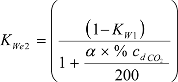
For the dilution air:
KWd = 1 – KW1

For the intake air:
KWa = 1 – KW2

where:
H a
=
intake air humidity, g water per kg dry air
H d
=
dilution air humidity, g water per kg dry air
and may be derived from relative humidity measurement, dewpoint measurement, vapour pressure measurement or dry/wet bulb measurement using the generally accepted formulae.
5.3.NOx correction for humidity and temperature
As the NOx emission depends on ambient air conditions, the NOx concentration shall be corrected for ambient air temperature and humidity with the factors given in the following formulae. The factors are valid in the range between 0 and 25 g/kg dry air.
(a)
for compression ignition engines:

with:
T a
=
temperature of the intake air, K
H a
=
humidity of the intake air, g water per kg dry air
where:
H a may be derived from relative humidity measurement, dewpoint measurement, vapour pressure measurement or dry/wet bulb measurement using the generally accepted formulae.
(b)
for spark ignition engines
k h.G = 0,6272 + 44,030 × 10–3 × H a - 0,862 × 10–3 × H a 2
where:
H a may be derived from relative humidity measurement, dew point measurement, vapour pressure measurement or dry/wet bulb measurement using the generally accepted formulae.
5.4.Calculation of the emission mass flow rates
The emission mass flow rate (g/h) for each mode shall be calculated as follows. For the calculation of NOx, the humidity correction factor k h,D, or k h,G, as applicable, as determined according to section 5.3, shall be used.
The measured concentration shall be converted to a wet basis according to section 5.2 if not already measured on a wet basis. Values for u gas are given in Table 6 for selected components based on ideal gas properties and the fuels relevant for this Directive.
(a)
for the raw exhaust gas
m gas = u gas × c gas × q mew
where:
u gas
=
ratio between density of exhaust component and density of exhaust gas
c gas
=
concentration of the respective component in the raw exhaust gas, ppm
q mew
=
exhaust mass flow rate, kg/h
(b)
for the diluted gas
m gas = u gas × c gas,c × q mdew
where:
u gas
=
ratio between density of exhaust component and density of air
c gas,c
=
background corrected concentration of the respective component in the diluted exhaust gas, ppm
q mdew
=
diluted exhaust mass flow rate, kg/h
where:

The dilution factor D shall be calculated according to section 5.4.1 of Appendix 2 to this Annex.
5.5.Calculation of the specific emissions
The emissions (g/kWh) shall be calculated for all individual components in the following way:

where:
m gas is the mass of individual gas
P n is the net power determined according to section 8.2 in Annex II.
The weighting factors used in the above calculation are according to section 2.7.1.
Table 6
Values of u gas in the raw and dilute exhaust gas for various exhaust components
| Notes: | ||||||
| ||||||
| Fuel | NOx | CO | THC/NMHC | CO2 | CH4 | |
|---|---|---|---|---|---|---|
| Diesel | Exhaust raw | 0,001587 | 0,000966 | 0,000479 | 0,001518 | 0,000553 |
| Exhaust dilute | 0,001588 | 0,000967 | 0,000480 | 0,001519 | 0,000553 | |
| Ethanol | Exhaust raw | 0,001609 | 0,000980 | 0,000805 | 0,001539 | 0,000561 |
| Exhaust dilute | 0,001588 | 0,000967 | 0,000795 | 0,001519 | 0,000553 | |
| CNG | Exhaust raw | 0,001622 | 0,000987 | 0,000523 | 0,001552 | 0,000565 |
| Exhaust dilute | 0,001588 | 0,000967 | 0,000584 | 0,001519 | 0,000553 | |
| Propane | Exhaust raw | 0,001603 | 0,000976 | 0,000511 | 0,001533 | 0,000559 |
| Exhaust dilute | 0,001588 | 0,000967 | 0,000507 | 0,001519 | 0,000553 | |
| Butane | Exhaust raw | 0,001600 | 0,000974 | 0,000505 | 0,001530 | 0,000558 |
| Exhaust dilute | 0,001588 | 0,000967 | 0,000501 | 0,001519 | 0,000553 | |
5.6.Calculation of the area control values
For the three control points selected according to section 2.7.6, the NOx emission shall be measured and calculated according to section 5.6.1 and also determined by interpolation from the modes of the test cycle closest to the respective control point according to section 5.6.2. The measured values are then compared to the interpolated values according to section 5.6.3.
5.6.1.Calculation of the Specific Emission
The NOx emission for each of the control points (Z) shall be calculated as follows:
m NOx,Z = 0,001587 × c NOx,Z × k h,D × q mew

5.6.2.Determination of the Emission Value from the Test Cycle
The NOx emission for each of the control points shall be interpolated from the four closest modes of the test cycle that envelop the selected control point Z as shown in Figure 4. For these modes (R, S, T, U), the following definitions apply:
Speed(R) = Speed(T) = nRT
Speed(S) = Speed(U) = nSU
Per cent load(R) = Per cent load(S)
Per cent load(T) = Per cent load(U).
The NOx emission of the selected control point Z shall be calculated as follows:

and:


where:
ER, ES, ET, EU = specific NOx emission of the enveloping modes calculated in accordance with section 5.6.1.
MR, MS, MT, MU = engine torque of the enveloping modes.

5.6.3.Comparison of NOx Emission Values
The measured specific NOx emission of the control point Z (NOx,Z) is compared to the interpolated value (EZ) as follows:

6.CALCULATION OF THE PARTICULATE EMISSIONS
6.1.Data Evaluation
For the evaluation of the particulates, the total sample masses (m sep) through the filter shall be recorded for each mode.
The filter shall be returned to the weighing chamber and conditioned for at least one hour, but not more than 80 hours, and then weighed. The gross weight of the filters shall be recorded and the tare weight (see section 2.1) subtracted, which results in the particulate sample mass m f.
If background correction is to be applied, the dilution air mass (m d) through the filter and the particulate mass (m f,d) shall be recorded. If more than one measurement was made, the quotient m f,d/m d shall be calculated for each single measurement and the values averaged.
6.2.Partial Flow Dilution System
The final reported test results of the particulate emission shall be determined through the following steps. Since various types of dilution rate control may be used, different calculation methods for q medf apply. All calculations shall be based upon the average values of the individual modes during the sampling period.
6.2.1.Isokinetic systems
q medf = q mew × rd

where r a corresponds to the ratio of the cross sectional areas of the isokinetic probe and the exhaust pipe:

6.2.2.Systems with measurement of CO2 or NOx concentration
qmedf = qmew × rd

where:
c wE
=
wet concentration of the tracer gas in the raw exhaust
c wD
=
wet concentration of the tracer gas in the diluted exhaust
c wA
=
wet concentration of the tracer gas in the dilution air
Concentrations measured on a dry basis shall be converted to a wet basis according to section 5.2 of this Appendix.
6.2.3.Systems with CO2 measurement and carbon balance method(14)

where:
c (CO2)D
=
CO2 concentration of the diluted exhaust
c (CO2)A
=
CO2 concentration of the dilution air
(concentrations in vol % on wet basis)
This equation is based upon the carbon balance assumption (carbon atoms supplied to the engine are emitted as CO2) and determined through the following steps:
qmedf = qmew × r d
and

6.2.4.Systems with flow measurement
qmedf = qmew × rd

6.3.Full Flow Dilution System
All calculations shall be based upon the average values of the individual modes during the sampling period. The diluted exhaust gas flow q mdew shall be determined in accordance with section 4.1 of Appendix 2 to this Annex. The total sample mass m sep shall be calculated in accordance with section 6.2.1 of Appendix 2 to this Annex.
6.4.Calculation of the Particulate Mass Flow Rate
The particulate mass flow rate shall be calculated as follows. If a full flow dilution system is used, q medf as determined according to section 6.2 shall be replaced with q mdew as determined according to section 6.3.


i = 1, … n
The particulate mass flow rate may be background corrected as follows:
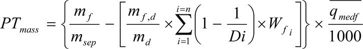
where D shall be calculated in accordance with section 5.4.1 of Appendix 2 to this Annex.’
(v)
Former section 6 is renumbered as section 7.
(f)
Appendix 2 is amended as follows:
(i)
Section 3 is replaced by the following:
‘3.EMISSIONS TEST RUN
At the manufacturers request, a dummy test may be run for conditioning of the engine and exhaust system before the measurement cycle.
NG and LPG fuelled engines shall be run-in using the ETC test. The engine shall be run over a minimum of two ETC cycles and until the CO emission measured over one ETC cycle does not exceed by more than 10 % the CO emission measured over the previous ETC cycle.
3.1.Preparation of the sampling filters (if applicable)
At least one hour before the test, each filter shall be placed in a partially covered petri dish, which is protected against dust contamination, and placed in a weighing chamber for stabilisation. At the end of the stabilisation period, each filter shall be weighed and the tare weight shall be recorded. The filter shall then be stored in a closed petri dish or sealed filter holder until needed for testing. The filter shall be used within eight hours of its removal from the weighing chamber. The tare weight shall be recorded.
3.2.Installation of the measuring equipment
The instrumentation and sample probes shall be installed as required. The tailpipe shall be connected to the full flow dilution system, if used.
3.3.Starting the dilution system and the engine
The dilution system and the engine shall be started and warmed up until all temperatures and pressures have stabilised at maximum power according to the recommendation of the manufacturer and good engineering practice.
3.4.Starting the particulate sampling system (diesel engines only)
The particulate sampling system shall be started and running on by-pass. The particulate background level of the dilution air may be determined by passing dilution air through the particulate filters. If filtered dilution air is used, one measurement may be done prior to or after the test. If the dilution air is not filtered, measurements at the beginning and at the end of the cycle may be done and the values averaged.
The dilution system and the engine shall be started and warmed up until all temperatures and pressures have stabilised according to the recommendation of the manufacturer and good engineering practice.
In case of periodic regeneration aftertreatment, the regeneration shall not occur during the warm-up of the engine.
3.5.Adjustment of the dilution system
The flow rates of the dilution system (full flow or partial flow) shall be set to eliminate water condensation in the system, and to obtain a maximum filter face temperature of 325 K (52 °C) or less (see section 2.3.1 of Annex V, DT).
3.6.Checking the analysers
The emission analysers shall be set at zero and spanned. If sample bags are used, they shall be evacuated.
3.7.Engine starting procedure
The stabilised engine shall be started according to the manufacturer's recommended starting procedure in the owner's manual, using either a production starter motor or the dynamometer. Optionally, the test may start directly from the engine preconditioning phase without shutting the engine off, when the engine has reached the idle speed.
3.8.Test cycle
3.8.1.Test sequence
The test sequence shall be started, if the engine has reached idle speed. The test shall be performed according to the reference cycle as set out in section 2 of this Appendix. Engine speed and torque command set points shall be issued at 5 Hz (10 Hz recommended) or greater. Feedback engine speed and torque shall be recorded at least once every second during the test cycle, and the signals may be electronically filtered.
3.8.2.Gaseous emissions measurement
3.8.2.1.Full flow dilution system
At the start of the engine or test sequence, if the cycle is started directly from the preconditioning, the measuring equipment shall be started, simultaneously:
start collecting or analysing dilution air,
start collecting or analysing diluted exhaust gas,
start measuring the amount of diluted exhaust gas (CVS) and the required temperatures and pressures,
start recording the feedback data of speed and torque of the dynamometer.
HC and NOx shall be measured continuously in the dilution tunnel with a frequency of 2 Hz. The average concentrations shall be determined by integrating the analyzer signals over the test cycle. The system response time shall be no greater than 20 s, and shall be coordinated with CVS flow fluctuations and sampling time/test cycle offsets, if necessary. CO, CO2, NMHC and CH4 shall be determined by integration or by analysing the concentrations in the sample bag, collected over the cycle. The concentrations of the gaseous pollutants in the dilution air shall be determined by integration or by collecting into the background bag. All other values shall be recorded with a minimum of one measurement per second (1 Hz).
3.8.2.2.Raw exhaust measurement
At the start of the engine or test sequence, if the cycle is started directly from the preconditioning, the measuring equipment shall be started, simultaneously:
start analysing the raw exhaust gas concentrations,
start measuring the exhaust gas or intake air and fuel flow rate,
start recording the feedback data of speed and torque of the dynamometer.
For the evaluation of the gaseous emissions, the emission concentrations (HC, CO and NOx) and the exhaust gas mass flow rate shall be recorded and stored with at least 2 Hz on a computer system. The system response time shall be no greater than 10 s. All other data may be recorded with a sample rate of at least 1 Hz. For analogue analysers the response shall be recorded, and the calibration data may be applied online or offline during the data evaluation.
For calculation of the mass emission of the gaseous components the traces of the recorded concentrations and the trace of the exhaust gas mass flow rate shall be time aligned by the transformation time as defined in section 2 of Annex I. Therefore, the response time of each gaseous emissions analyser and of the exhaust gas mass flow system shall be determined according to the provisions of section 4.2.1 and section 1.5 of Appendix 5 to this Annex and recorded.
3.8.3.Particulate sampling (if applicable)
3.8.3.1.Full flow dilution system
At the start of the engine or test sequence, if the cycle is started directly from the preconditioning, the particulate sampling system shall be switched from by-pass to collecting particulates.
If no flow compensation is used, the sample pump(s) shall be adjusted so that the flow rate through the particulate sample probe or transfer tube is maintained at a value within ± 5 % of the set flow rate. If flow compensation (i.e., proportional control of sample flow) is used, it must be demonstrated that the ratio of main tunnel flow to particulate sample flow does not change by more than ± 5 % of its set value (except for the first 10 seconds of sampling).
Note: For double dilution operation, sample flow is the net difference between the flow rate through the sample filters and the secondary dilution air flow rate.
The average temperature and pressure at the gas meter(s) or flow instrumentation inlet shall be recorded. If the set flow rate cannot be maintained over the complete cycle (within ± 5 %) because of high particulate loading on the filter, the test shall be voided. The test shall be rerun using a lower flow rate and/or a larger diameter filter.
3.8.3.2.Partial flow dilution system
At the start of the engine or test sequence, if the cycle is started directly from the preconditioning, the particulate sampling system shall be switched from by-pass to collecting particulates.
For the control of a partial flow dilution system, a fast system response is required. The transformation time for the system shall be determined by the procedure in section 3.3 of Appendix 5 to Annex III. If the combined transformation time of the exhaust flow measurement (see section 4.2.1) and the partial flow system is less than 0,3 sec, online control may be used. If the transformation time exceeds 0,3 sec, look ahead control based on a pre-recorded test run must be used. In this case, the rise time shall be ≤ 1 sec and the delay time of the combination ≤ 10 sec.
The total system response shall be designed as to ensure a representative sample of the particulates, qmp,i, proportional to the exhaust mass flow. To determine the proportionality, a regression analysis of qmp,i versus qmew,i shall be conducted on a minimum 1 Hz data acquisition rate, and the following criteria shall be met:
The correlation coefficient R2 of the linear regression between qmp,i and qmew,i shall not be less than 0,95,
The standard error of estimate of qmp,i on qmew,i shall not exceed 5 % of qmp maximum,
qmp intercept of the regression line shall not exceed ± 2 % of qmp maximum.
Optionally, a pretest may be run, and the exhaust mass flow signal of the pretest be used for controlling the sample flow into the particulate system (look-ahead control). Such a procedure is required if the transformation time of the particulate system, t50,P or the transformation time of the exhaust mass flow signal, t50,F, or both, are > 0,3 sec. A correct control of the partial dilution system is obtained, if the time trace of qmew,pre of the pretest, which controls qmp, is shifted by a look-ahead time of t50,P + t50,F.
For establishing the correlation between qmp,i and qmew,i the data taken during the actual test shall be used, with qmew,i time aligned by t50,F relative to qmp,i (no contribution from t50,P to the time alignment). That is, the time shift between qmew and qmp is the difference in their transformation times that were determined in section 3.3 of Appendix 5 to Annex III.
3.8.4.Engine stalling
If the engine stalls anywhere during the test cycle, the engine shall be preconditioned and restarted, and the test repeated. If a malfunction occurs in any of the required test equipment during the test cycle, the test shall be voided.
3.8.5.Operations after test
At the completion of the test, the measurement of the diluted exhaust gas volume or raw exhaust gas flow rate, the gas flow into the collecting bags and the particulate sample pump shall be stopped. For an integrating analyser system, sampling shall continue until system response times have elapsed.
The concentrations of the collecting bags, if used, shall be analysed as soon as possible and in any case not later than 20 minutes after the end of the test cycle.
After the emission test, a zero gas and the same span gas shall be used for re-checking the analysers. The test will be considered acceptable if the difference between the pre-test and post-test results is less than 2 % of the span gas value.
3.9.Verification of the test run
3.9.1.Data shift
To minimise the biasing effect of the time lag between the feedback and reference cycle values, the entire engine speed and torque feedback signal sequence may be advanced or delayed in time with respect to the reference speed and torque sequence. If the feedback signals are shifted, both speed and torque must be shifted the same amount in the same direction.
3.9.2.Calculation of the cycle work
The actual cycle work Wact (kWh) shall be calculated using each pair of engine feedback speed and torque values recorded. This shall be done after any feedback data shift has occurred, if this option is selected. The actual cycle work Wact is used for comparison to the reference cycle work Wref and for calculating the brake specific emissions (see sections 4.4 and 5.2). The same methodology shall be used for integrating both reference and actual engine power. If values are to be determined between adjacent reference or adjacent measured values, linear interpolation shall be used.
In integrating the reference and actual cycle work, all negative torque values shall be set equal to zero and included. If integration is performed at a frequency of less than 5 Hertz, and if, during a given time segment, the torque value changes from positive to negative or negative to positive, the negative portion shall be computed and set equal to zero. The positive portion shall be included in the integrated value.
Wact shall be between – 15 % and + 5 % of Wref
3.9.3.Validation statistics of the test cycle
Linear regressions of the feedback values on the reference values shall be performed for speed, torque and power. This shall be done after any feedback data shift has occurred, if this option is selected. The method of least squares shall be used, with the best fit equation having the form:
y = mx + b
where:
y
=
Feedback (actual) value of speed (min-1), torque (Nm), or power (kW)
m
=
slope of the regression line
x
=
reference value of speed (min-1), torque (Nm), or power (kW)
b
=
y intercept of the regression line
The standard error of estimate (SE) of y on x and the coefficient of determination (r2) shall be calculated for each regression line.
It is recommended that this analysis be performed at 1 Hertz. All negative reference torque values and the associated feedback values shall be deleted from the calculation of cycle torque and power validation statistics. For a test to be considered valid, the criteria of table 7 must be met.
Table 7
Regression line tolerances
| a Until 1 October 2005, the figures shown in brackets may be used for the type-approval testing of gas engines. (The Commission shall report on the development of gas engine technology to confirm or modify the regression line tolerances applicable to gas engines given in this table.) | |||
| Speed | Torque | Power | |
|---|---|---|---|
| Standard error of estimate (SE) of Y on X | Max 100 min–1 | Max 13 % (15 %)a of power map maximum engine torque | Max 8 % (15 %)a of power map maximum engine power |
| Slope of the regression line, m | 0,95 to 1,03 | 0,83–1,03 | 0,89–1,03 (0,83–1,03)a |
| Coefficient of determination, r2 | min 0,9700 (min 0,9500)a | min 0,8800 (min 0,7500)a | min 0,9100 (min 0,7500)a |
| Y intercept of the regression line, b | ± 50 min–1 | ± 20 Nm or ± 2 % (± 20 Nm or ± 3 %)a of max torque whichever is greater | ± 4 kW or ± 2 % (± 4 kW or ± 3 %)a of max power whichever is greater |
Point deletions from the regression analyses are permitted where noted in Table 8.
Table 8
Permitted point deletions from regression analysis
| Conditions | Points to be deleted |
|---|---|
| Full load demand and torque feedback < 95 % torque reference | Torque and/or power |
| Full load demand and speed feedback < 95 % speed reference | Speed and/or power |
| No load, not an idle point, and torque feedback > torque reference | Torque and/or power |
| No load, speed feedback ≤ idle speed + 50 min–1 and torque feedback = manufacturer defined/measured idle torque ± 2 % of max. torque | Speed and/or power |
| No load, speed feedback > idle speed + 50 min–1 and torque feedback > 105 % torque reference | Torque and/or power |
| No load and speed feedback > 105 % speed reference | Speed and/or power’ |
(ii)
The following section 4 is inserted:
‘4.CALCULATION OF THE EXHAUST GAS FLOW
4.1.Determination of the diluted exhaust gas flow
The total diluted exhaust gas flow over the cycle (kg/test) shall be calculated from the measurement values over the cycle and the corresponding calibration data of the flow measurement device (V 0 for PDP, K V for CFV, C d for SSV), as determined in section 2 of Appendix 5 to Annex III). The following formulae shall be applied, if the temperature of the diluted exhaust is kept constant over the cycle by using a heat exchanger (± 6 K for a PDP-CVS, ± 11 K for a CFV-CVS or ± 11 K for a SSV-CVS), see section 2.3 of Annex V).
For the PDP-CVS system:
m ed = 1,293 × V 0 × N P × (p b - p 1) × 273 / (101,3 × T)
where:
V 0
=
volume of gas pumped per revolution under test conditions, m3/rev
N P
=
total revolutions of pump per test
p b
=
atmospheric pressure in the test cell, kPa
p 1
=
pressure depression below atmospheric at pump inlet, kPa
T
=
average temperature of the diluted exhaust gas at pump inlet over the cycle, K
For the CFV-CVS system:
m ed = 1,293 × t × K v × p p / T 0,5
where:
t
=
cycle time, s
K v
=
calibration coefficient of the critical flow venturi for standard conditions,
p p
=
absolute pressure at venturi inlet, kPa
T
=
absolute temperature at venturi inlet, K
For the SSV-CVS system
m ed = 1,293 × QSSV
where:

with:
A 0
=
collection of constants and units conversions

= 0,006111 in SI units of
d
=
diameter of the SSV throat, m
C d
=
discharge coefficient of the SSV
p p
=
absolute pressure at venturi inlet, kPa
T
=
temperature at the venturi inlet, K
r p
=
ratio of the SSV throat to inlet absolute, static pressure = 
rD
=
ratio of the SSV throat diameter, d, to the inlet pipe inner diameter = 
If a system with flow compensation is used (i.e. without heat exchanger), the instantaneous mass emissions shall be calculated and integrated over the cycle. In this case, the instantaneous mass of the diluted exhaust gas shall be calculated as follows.
For the PDP-CVS system:
m ed,i = 1,293 × V 0 × N P,i × (p b - p 1) × 273 / (101,3 × T)
where:
N P,i = total revolutions of pump per time interval
For the CFV-CVS system:
m ed,i = 1,293 × Δt i × K V × p p / T 0,5
where:
Δt i = time interval, s
For the SSV-CVS system:
med = 1,293 × QSSV × Δti
where:
Δt i = time interval, s
The real time calculation shall be initialised with either a reasonable value for C d, such as 0,98, or a reasonable value of Q ssv. If the calculation is initialised with Q ssv, the initial value of Q ssv shall be used to evaluate Re.
During all emissions tests, the Reynolds number at the SSV throat must be in the range of Reynolds numbers used to derive the calibration curve developed in section 2.4 of Appendix 5 to this Annex.
4.2.Determination of raw exhaust gas mass flow
For calculation of the emissions in the raw exhaust gas and for controlling of a partial flow dilution system, it is necessary to know the exhaust gas mass flow rate. For the determination of the exhaust mass flow rate, either of the methods described in sections 4.2.2 to 4.2.5 may be used.
4.2.1.Response time
For the purpose of emissions calculation, the response time of either method described below shall be equal to or less than the requirement for the analyzer response time, as defined in section 1.5 of Appendix 5 to this Annex.
For the purpose of controlling of a partial flow dilution system, a faster response is required. For partial flow dilution systems with online control, a response time of ≤ 0,3 seconds is required. For partial flow dilution systems with look ahead control based on a pre-recorded test run, a response time of the exhaust flow measurement system of ≤ 5 seconds with a rise time of ≤ 1 second is required. The system response time shall be specified by the instrument manufacturer. The combined response time requirements for exhaust gas flow and partial flow dilution system are indicated in section 3.8.3.2.
4.2.2.Direct measurement method
Direct measurement of the instantaneous exhaust flow may be done by systems such as:
pressure differential devices, like flow nozzle,
ultrasonic flowmeter,
vortex flowmeter.
Precautions shall be taken to avoid measurement errors which will impact emission value errors. Such precautions include the careful installation of the device in the engine exhaust system according to the instrument manufacturers' recommendations and to good engineering practice. Engine performance and emissions shall especially not be affected by the installation of the device.
The accuracy of exhaust flow determination shall be at least ± 2,5 % of reading or ± 1,5 % of engine's maximum value, whichever is the greater.
4.2.3.Air and fuel measurement method
This involves measurement of the air flow and the fuel flow. Air flowmeters and fuel flowmeters shall be used that meet the total exhaust flow accuracy requirement of section 4.2.2. The calculation of the exhaust gas flow is as follows:
qmew = qmaw + qmf
4.2.4.Tracer measurement method
This involves measurement of the concentration of a tracer gas in the exhaust. A known amount of an inert gas (e.g. pure helium) shall be injected into the exhaust gas flow as a tracer. The gas is mixed and diluted by the exhaust gas, but shall not react in the exhaust pipe. The concentration of the gas shall then be measured in the exhaust gas sample.
In order to ensure complete mixing of the tracer gas, the exhaust gas sampling probe shall be located at least 1 m or 30 times the diameter of the exhaust pipe, whichever is larger, downstream of the tracer gas injection point. The sampling probe may be located closer to the injection point if complete mixing is verified by comparing the tracer gas concentration with the reference concentration when the tracer gas is injected upstream of the engine.
The tracer gas flow rate shall be set so that the tracer gas concentration at engine idle speed after mixing becomes lower than the full scale of the trace gas analyser.
The calculation of the exhaust gas flow is as follows:

where:
q mew,i
=
instantaneous exhaust mass flow, kg/s
q vt
=
tracer gas flow, cm3/min
c mix.i
=
instantaneous concentration of the tracer gas after mixing, ppm
ρ e
=
density of the exhaust gas, kg/m3 (cf. table 3)
c a
=
background concentration of the tracer gas in the intake air, ppm
When the background concentration is less than 1 % of the concentration of the tracer gas after mixing (c mix.i) at maximum exhaust flow, the background concentration may be neglected.
The total system shall meet the accuracy specifications for the exhaust gas flow, and shall be calibrated according to section 1.7 of Appendix 5 to this Annex.
4.2.5.Air flow and air-to-fuel ratio measurement method
This involves exhaust mass calculation from the air flow and the air to fuel ratio. The calculation of the instantaneous exhaust gas mass flow is as follows:

with:


where:
A/F st
=
stoichiometric air to fuel ratio, kg/kg
λ
=
excess air ratio
c CO2
=
dry CO2 concentration, %
c CO
=
dry CO concentration, ppm
c HC
=
HC concentration, ppm
Note: β can be 1 for fuels containing carbon and 0 for hydrogen fuel.
The air flowmeter shall meet the accuracy specifications of section 2.2 of Appendix 4 to this Annex, the CO2 analyser used shall meet the specifications of section 3.3.2 of Appendix 4 to this Annex and the total system shall meet the accuracy specifications for the exhaust gas flow.
Optionally, air to fuel ratio measurement equipment such as a zirconia type sensor may be used for the measurement of the excess air ratio which meets the specifications of section 3.3.6 of Appendix 4 to this Annex.’
(iii)
Sections 4 and 5 are replaced by the following:
‘5.CALCULATION OF THE GASEOUS EMISSIONS
5.1.Data evaluation
For the evaluation of the gaseous emissions in the diluted exhaust gas, the emission concentrations (HC, CO and NOx) and the diluted exhaust gas mass flow rate shall be recorded according to section 3.8.2.1 and stored on a computer system. For analogue analysers the response shall be recorded, and the calibration data may be applied online or offline during the data evaluation.
For the evaluation of the gaseous emissions in the raw exhaust gas, the emission concentrations (HC, CO and NOx) and the exhaust gas mass flow rate shall be recorded according to section 3.8.2.2 and stored on a computer system. For analogue analysers the response shall be recorded, and the calibration data may be applied online or offline during the data evaluation.
5.2.Dry/wet correction
If the concentration is measured on a dry basis, it shall be converted to a wet basis according to the following formula. For continuous measurement, the conversion shall be applied to each instantaneous measurement before any further calculation.
cwet = kW × cdry
The conversion equations of section 5.2 of Appendix 1 to this Annex shall apply.
5.3.NOx correction for humidity and temperature
As the NOx emission depends on ambient air conditions, the NOx concentration shall be corrected for ambient air temperature and humidity with the factors given in section 5.3 of Appendix 1 to this Annex. The factors are valid in the range between 0 and 25 g/kg dry air.
5.4.Calculation of the emission mass flow rates
The emission mass over the cycle (g/test) shall be calculated as follows depending on the measurement method applied. The measured concentration shall be converted to a wet basis according to section 5.2 of Appendix 1 to this Annex, if not already measured on a wet basis. The respective values for u gas shall be applied that are given in Table 6 of Appendix 1 to this Annex for selected components based on ideal gas properties and the fuels relevant for this Directive.
(a)
for the raw exhaust gas:

where:
u gas
=
ratio between density of exhaust component and density of exhaust gas from table 6
c gas,i
=
instantaneous concentration of the respective component in the raw exhaust gas, ppm
q mew,i
=
instantaneous exhaust mass flow rate, kg/s
f
=
data sampling rate, Hz
n
=
number of measurements
(b)
for the diluted exhaust gas without flow compensation:
mgas = ugas × cgas × med
where:
u gas
=
ratio between density of exhaust component and density of air from table 6
c gas
=
average background corrected concentration of the respective component, ppm
m ed
=
total diluted exhaust mass over the cycle, kg
(c)
for the diluted exhaust gas with flow compensation:

where:
c e,i
=
instantaneous concentration of the respective component measured in the diluted exhaust gas, ppm
c d
=
concentration of the respective component measured in the dilution air, ppm
q mdew,i
=
instantaneous diluted exhaust gas mass flow rate, kg/s
m ed
=
total mass of diluted exhaust gas over the cycle, kg
u gas
=
ratio between density of exhaust component and density of air from table 6
D
=
dilution factor (see section 5.4.1)
If applicable, the concentration of NMHC and CH4 shall be calculated by either of the methods shown in section 3.3.4 of Appendix 4 to this Annex, as follows:
(a)
GC method (full flow dilution system, only):
cNMHC = cHC – cCH4
(b)
NMC method:


where:
c HC(w/Cutter)
=
HC concentration with the sample gas flowing through the NMC
c HC(w/oCutter)
=
HC concentration with the sample gas bypassing the NMC
5.4.1.Determination of the background corrected concentrations (full flow dilution system, only)
The average background concentration of the gaseous pollutants in the dilution air shall be subtracted from measured concentrations to get the net concentrations of the pollutants. The average values of the background concentrations can be determined by the sample bag method or by continuous measurement with integration. The following formula shall be used.

where:
c e
=
concentration of the respective pollutant measured in the diluted exhaust gas, ppm
c d
=
concentration of the respective pollutant measured in the dilution air, ppm
D
=
dilution factor
The dilution factor shall be calculated as follows:
(a)
for diesel and LPG fueled gas engines

(b)
for NG fueled gas engines

where:
c CO2
=
concentration of CO2 in the diluted exhaust gas, % vol
c HC
=
concentration of HC in the diluted exhaust gas, ppm C1
c NMHC
=
concentration of NMHC in the diluted exhaust gas, ppm C1
c CO
=
concentration of CO in the diluted exhaust gas, ppm
F S
=
stoichiometric factor
Concentrations measured on dry basis shall be converted to a wet basis in accordance with section 5.2 of Appendix 1 to this Annex.
The stoichiometric factor shall be calculated as follows:

where:
α, ε are the molar ratios referring to a fuel CH α O ε
Alternatively, if the fuel composition is not known, the following stoichiometric factors may be used:
F S (diesel)
=
13,4
F S (LPG)
=
11,6
F S (NG)
=
9,5
5.5.Calculation of the specific emissions
The emissions (g/kWh) shall be calculated in the following way:
(a)
all components, except NOx:

(b)
NOx:

where:
W act = actual cycle work as determined according to section 3.9.2.
5.5.1.In case of a periodic exhaust aftertreatment system, the emissions shall be weighted as follows:

where:
n1
=
number of ETC tests between two regenerations
n2
=
number of ETC during a regeneration (minimum of one ETC test)
M gas,n2
=
emissions during a regeneration
M gas,n1
=
emissions after a regeneration.
6.CALCULATION OF THE PARTICULATE EMISSION (IF APPLICABLE)
6.1.Data evaluation
The particulate filter shall be returned to the weighing chamber no later than one hour after completion of the test. It shall be conditioned in a partially covered petri dish, which is protected against dust contamination, for at least one hour, but not more than 80 hours, and then weighed. The gross weight of the filters shall be recorded and the tare weight subtracted, which results in the particulate sample mass m f. For the evaluation of the particulate concentration, the total sample mass (m sep) through the filters over the test cycle shall be recorded.
If background correction is to be applied, the dilution air mass (m d) through the filter and the particulate mass (m f,d) shall be recorded.
6.2.Calculation of the mass flow
6.2.1.Full flow dilution system
The particulate mass (g/test) shall be calculated as follows:

where:
m f
=
particulate mass sampled over the cycle, mg
m sep
=
mass of diluted exhaust gas passing the particulate collection filters, kg
m ed
=
mass of diluted exhaust gas over the cycle, kg
If a double dilution system is used, the mass of the secondary dilution air shall be subtracted from the total mass of the double diluted exhaust gas sampled through the particulate filters.
msep = mset – mssd
where:
m set
=
mass of double diluted exhaust gas through particulate filter, kg
m ssd
=
mass of secondary dilution air, kg
If the particulate background level of the dilution air is determined in accordance with section 3.4, the particulate mass may be background corrected. In this case, the particulate mass (g/test) shall be calculated as follows:

where:
mPT, msep, med
=
see above
md
=
mass of primary dilution air sampled by background particulate sampler, kg
mf,d
=
mass of the collected background particulates of the primary dilution air, mg
D
=
dilution factor as determined in section 5.4.1.
6.2.2.Partial flow dilution system
The mass of particulates (g/test) shall be calculated by either of the following methods:
(a)

where:
m f
=
particulate mass sampled over the cycle, mg
m sep
=
mass of diluted exhaust gas passing the particulate collection filters, kg
m edf
=
mass of equivalent diluted exhaust gas over the cycle, kg
The total mass of equivalent diluted exhaust gas mass over the cycle shall be determined as follows:


where:
q medf,i
=
instantaneous equivalent diluted exhaust mass flow rate, kg/s
q mew,i
=
instantaneous exhaust mass flow rate, kg/s
r d,i
=
instantaneous dilution ratio
q mdew,i
=
instantaneous diluted exhaust mass flow rate through dilution tunnel, kg/s
q mdw,i
=
instantaneous dilution air mass flow rate, kg/s
f
=
data sampling rate, Hz
n
=
number of measurements
(b)
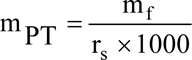
where:
m f
=
particulate mass sampled over the cycle, mg
r s
=
average sample ratio over the test cycle
with:

where:
m se
=
sample mass over the cycle, kg
m ew
=
total exhaust mass flow over the cycle, kg
m sep
=
mass of diluted exhaust gas passing the particulate collection filters, kg
m sed
=
mass of diluted exhaust gas passing the dilution tunnel, kg.
Note: In case of the total sampling type system, m sep and M sed are identical.
6.3.Calculation of the Specific Emission
The particulate emission (g/kWh) shall be calculated in the following way:

where:
W act = actual cycle work as determined according to section 3.9.2, kWh.
6.3.1.In case of a periodic regeneration aftertreatment system, the emissions shall be weighted as follows:

where:
n1
=
number of ETC tests between two regeneration events
n2
=
number of ETC tests during a regeneration (minimum of one ETC)

=
emissions during a regeneration

=
emissions outside a regeneration.’
(g)
Appendix 4 is amended as follows:
(i)
Section 1 is replaced by the following:
‘1.INTRODUCTION
Gaseous components, particulates, and smoke emitted by the engine submitted for testing shall be measured by the methods described in Annex V. The respective sections of Annex V describe the recommended analytical systems for the gaseous emissions (section 1), the recommended particulate dilution and sampling systems (section 2), and the recommended opacimeters for smoke measurement (section 3).
For the ESC, the gaseous components shall be determined in the raw exhaust gas. Optionally, they may be determined in the diluted exhaust gas, if a full flow dilution system is used for particulate determination. Particulates shall be determined with either a partial flow or a full flow dilution system.
For the ETC, the following systems may be used
a CVS full flow dilution system for determining gaseous and particulate emissions (double dilution systems are permissible),
or
a combination of raw exhaust measurement for the gaseous emissions and a partial flow dilution system for particulate emissions,
or
any combination of the two principles (e.g. raw gaseous measurement and full flow particulate measurement).’
(ii)
Section 2.2 is replaced by the following:
‘2.2.Other instruments
Measuring instruments for fuel consumption, air consumption, temperature of coolant and lubricant, exhaust gas pressure and intake manifold depression, exhaust gas temperature, air intake temperature, atmospheric pressure, humidity and fuel temperature shall be used, as required. These instruments shall satisfy the requirements given in table 9:
Table 9
Accuracy of measuring instruments
| Measuring Instrument | Accuracy |
|---|---|
| Fuel Consumption | ± 2 % of Engine's Maximum Value |
| Air Consumption | ± 2 % of reading or ± 1 % of engine's maximum value whichever is greater |
| Exhaust Gas Flow | ± 2,5 % of reading or ± 1,5 % of engine's maximum value whichever is greater |
| Temperatures ≤ 600 K (327 °C) | ± 2 K Absolute |
| Temperatures ≥ 600 K (327 °C) | ± 1 % of Reading |
| Atmospheric Pressure | ± 0,1 kPa Absolute |
| Exhaust Gas Pressure | ± 0,2 kPa Absolute |
| Intake Depression | ± 0,05 kPa Absolute |
| Other Pressures | ± 0,1 kPa Absolute |
| Relative Humidity | ± 3 % Absolute |
| Absolute Humidity | ± 5 % of Reading |
| Dilution Air Flow | ± 2 % of Reading |
| Diluted Exhaust Gas Flow | ± 2 % of Reading’ |
(iii)
Sections 2.3 and 2.4 are deleted.
(iv)
Sections 3 and 4 are replaced by the following:
‘3.DETERMINATION OF THE GASEOUS COMPONENTS
3.1.General analyser specifications
The analysers shall have a measuring range appropriate for the accuracy required to measure the concentrations of the exhaust gas components (section 3.1.1). It is recommended that the analysers be operated such that the measured concentration falls between 15 % and 100 % of full scale.
If read-out systems (computers, data loggers) can provide sufficient accuracy and resolution below 15 % of full scale, measurements below 15 % of full scale are also acceptable. In this case, additional calibrations of at least 4 non-zero nominally equally spaced points are to be made to ensure the accuracy of the calibration curves according to section 1.6.4 of Appendix 5 to this Annex.
The electromagnetic compatibility (EMC) of the equipment shall be on a level as to minimise additional errors.
3.1.1.Accuracy
The analyser shall not deviate from the nominal calibration point by more than ± 2 % of the reading over the whole measurement range except zero, or ± 0,3 % of full scale whichever is larger. The accuracy shall be determined according to the calibration requirements laid down in section 1.6 of Appendix 5 to this Annex.
Note: For the purpose of this Directive, accuracy is defined as the deviation of the analyser reading from the nominal calibration values using a calibration gas (= true value).
3.1.2.Precision
The precision, defined as 2,5 times the standard deviation of 10 repetitive responses to a given calibration or span gas, has to be not greater than ± 1 % of full scale concentration for each range used above 155 ppm (or ppmC) or ± 2 % of each range used below 155 ppm (or ppmC).
3.1.3.Noise
The analyser peak-to-peak response to zero and calibration or span gases over any 10 second period shall not exceed 2 % of full scale on all ranges used.
3.1.4.Zero drift
Zero response is defined as the mean response, including noise, to a zero gas during a 30 seconds time interval. The drift of the zero response during a one hour period shall be less than 2 % of full scale on the lowest range used.
3.1.5.Span drift
Span response is defined as the mean response, including noise, to a span gas during a 30 seconds time interval. The drift of the span response during a one hour period shall be less than 2 % of full scale on the lowest range used.
3.1.6.Rise time
The rise time of the analyser installed in the measurement system shall not exceed 3,5 s.
Note: Only evaluating the response time of the analyser alone will not clearly define the suitability of the total system for transient testing. Volumes and especially dead volumes through out the system will not only effect the transportation time from the probe to the analyser, but also effect the rise time. Also transport times inside of an analyser would be defined as analyser response time, like the converter or water traps inside NOx analysers. The determination of the total system response time is described in section 1.5 of Appendix 5 to this Annex.
3.2.Gas drying
The optional gas drying device must have a minimal effect on the concentration of the measured gases. Chemical dryers are not an acceptable method of removing water from the sample.
3.3.Analysers
Sections 3.3.1 to 3.3.4 describe the measurement principles to be used. A detailed description of the measurement systems is given in Annex V. The gases to be measured shall be analysed with the following instruments. For non-linear analysers, the use of linearising circuits is permitted.
3.3.1.Carbon monoxide (CO) analysis
The carbon monoxide analyser shall be of the Non-Dispersive InfraRed (NDIR) absorption type.
3.3.2.Carbon dioxide (CO2) analysis
The carbon dioxide analyser shall be of the Non-Dispersive InfraRed (NDIR) absorption type.
3.3.3.Hydrocarbon (HC) analysis
For diesel and LPG fuelled gas engines, the hydrocarbon analyser shall be of the Heated Flame Ionisation Detector (HFID) type with detector, valves, pipework, etc. heated so as to maintain a gas temperature of 463 K ± 10 K (190 ± 10 °C). For NG fuelled gas engines, the hydrocarbon analyser may be of the non heated Flame Ionisation Detector (FID) type depending upon the method used (see section 1.3 of Annex V).
3.3.4.Non-Methane Hydrocarbon (NMHC) analysis (NG fuelled gas engines only)
Non-methane hydrocarbons shall be determined by either of the following methods:
3.3.4.1.Gas chromatographic (GC) method
Non-methane hydrocarbons shall be determined by subtraction of the methane analysed with a Gas Chromatograph (GC) conditioned at 423 K (150 °C) from the hydrocarbons measured according to section 3.3.3.
3.3.4.2.Non-Methane Cutter (NMC) method
The determination of the non-methane fraction shall be performed with a heated NMC operated in line with an FID as per section 3.3.3 by subtraction of the methane from the hydrocarbons.
3.3.5.Oxides of Nitrogen (NOx) analysis
The oxides of nitrogen analyser shall be of the ChemiLuminescent Detector (CLD) or Heated ChemiLuminescent Detector (HCLD) type with a NO2/NO converter, if measured on a dry basis. If measured on a wet basis, a HCLD with converter maintained above 328 K (55 °C) shall be used, provided the water quench check (see section 1.9.2.2 of Appendix 5 to this Annex) is satisfied.
3.3.6.Air-to-fuel measurement
The air to fuel measurement equipment used to determine the exhaust gas flow as specified in section 4.2.5 of Appendix 2 to this Annex shall be a wide range air to fuel ratio sensor or lambda sensor of Zirconia type. The sensor shall be mounted directly on the exhaust pipe where the exhaust gas temperature is high enough to eliminate water condensation.
The accuracy of the sensor with incorporated electronics shall be within:
± 3 % of reading
λ < 2
± 5 % of reading
2 ≤ λ < 5
± 10 % of reading
5 ≤ λ
To fulfil the accuracy specified above, the sensor shall be calibrated as specified by the instrument manufacturer.
3.4.Sampling of Gaseous Emissions
3.4.1.Raw exhaust gas
The gaseous emissions sampling probes shall be fitted at least 0,5 m or 3 times the diameter of the exhaust pipe — whichever is the larger — upstream of the exit of the exhaust gas system but sufficiently close to the engine as to ensure an exhaust gas temperature of at least 343 K (70 °C) at the probe.
In the case of a multi-cylinder engine with a branched exhaust manifold, the inlet of the probe shall be located sufficiently far downstream so as to ensure that the sample is representative of the average exhaust emissions from all cylinders. In multi-cylinder engines having distinct groups of manifolds, such as in a “Vee” engine configuration, it is recommended to combine the manifolds upstream of the sampling probe. If this is not practical, it is permissible to acquire a sample from the group with the highest CO2 emission. Other methods which have been shown to correlate with the above methods may be used. For exhaust emission calculation the total exhaust mass flow shall be used.
If the engine is equipped with an exhaust aftertreatment system, the exhaust sample shall be taken downstream of the exhaust aftertreatment system.
3.4.2.Diluted exhaust gas
The exhaust pipe between the engine and the full flow dilution system shall conform to the requirements of section 2.3.1 of Annex V (EP).
The gaseous emissions sample probe(s) shall be installed in the dilution tunnel at a point where the dilution air and exhaust gas are well mixed, and in close proximity to the particulates sampling probe.
Sampling can generally be done in two ways:
the pollutants are sampled into a sampling bag over the cycle and measured after completion of the test,
the pollutants are sampled continuously and integrated over the cycle; this method is mandatory for HC and NOx.
4.DETERMINATION OF THE PARTICULATES
The determination of the particulates requires a dilution system. Dilution may be accomplished by a partial flow dilution system or a full flow double dilution system. The flow capacity of the dilution system shall be large enough to completely eliminate water condensation in the dilution and sampling systems. The temperature of the diluted exhaust gas shall be below 325 K (52 °C)(15) immediately upstream of the filter holders. Humidity control of the dilution air before entering the dilution system is permitted, and especially dehumidifying is useful if dilution air humidity is high. The temperature of the dilution air shall be higher than 288 K (15 °C) in close proximity to the entrance into the dilution tunnel.
The partial flow dilution system has to be designed to extract a proportional raw exhaust sample from the engine exhaust stream, thus responding to excursions in the exhaust stream flow rate, and introduce dilution air to this sample to achieve a temperature below 325 K (52 °C) at the test filter. For this it is essential that the dilution ratio or the sampling ratio r dil or r s be determined such that the accuracy limits of section 3.2.1 of Appendix 5 to this Annex are fulfilled. Different extraction methods can be applied, whereby the type of extraction used dictates to a significant degree the sampling hardware and procedures to be used (section 2.2 of Annex V).
In general, the particulate sampling probe shall be installed in close proximity to the gaseous emissions sampling probe, but sufficiently distant as to not cause interference. Therefore, the installation provisions of section 3.4.1 also apply to particulate sampling. The sampling line shall conform to the requirements of section 2 of Annex V.
In the case of a multi-cylinder engine with a branched exhaust manifold, the inlet of the probe shall be located sufficiently far downstream so as to ensure that the sample is representative of the average exhaust emissions from all cylinders. In multi-cylinder engines having distinct groups of manifolds, such as in a “Vee” engine configuration, it is recommended to combine the manifolds upstream of the sampling probe. If this is not practical, it is permissible to acquire a sample from the group with the highest particulate emission. Other methods which have been shown to correlate with the above methods may be used. For exhaust emission calculation the total exhaust mass flow shall be used.
To determine the mass of the particulates, a particulate sampling system, particulate sampling filters, a microgram balance, and a temperature and humidity controlled weighing chamber, are required.
For particulate sampling, the single filter method shall be applied which uses one filter (see section 4.1.3) for the whole test cycle. For the ESC, considerable attention must be paid to sampling times and flows during the sampling phase of the test.
4.1.Particulate sampling filters
The diluted exhaust shall be sampled by a filter that meets the requirements of sections 4.1.1 and 4.1.2 during the test sequence.
4.1.1.Filter specification
Fluorocarbon coated glass fiber filters are required. All filter types shall have a 0,3 μm DOP (di-octylphthalate) collection efficiency of at least 99 % at a gas face velocity between 35 and 100 cm/s.
4.1.2.Filter size
Particulate filters with a diameter of 47 mm or 70 mm are recommended. Larger diameter filters are acceptable (section 4.1.4), but smaller diameter filters are not permitted.
4.1.3.Filter face velocity
A gas face velocity through the filter of 35 to 100 cm/s shall be achieved. The pressure drop increase between the beginning and the end of the test shall be no more than 25 kPa.
4.1.4.Filter loading
The required minimum filter loadings for the most common filter sizes are shown in table 10. For larger filter sizes, the minimum filter loading shall be 0,065 mg/1 000 mm2 filter area.
Table 10
Minimum Filter Loadings
| Filter Diameter (mm) | Minimum loading (mg) |
|---|---|
| 47 | 0,11 |
| 70 | 0,25 |
| 90 | 0,41 |
| 110 | 0,62 |
If, based on previous testing, the required minimum filter loading is unlikely to be reached on a test cycle after optimisation of flow rates and dilution ratio, a lower filter loading may be acceptable, with the agreement of the parties involved, if it can be shown to meet the accuracy requirements of section 4.2, e.g. with a 0,1 μg balance.
4.1.5.Filter holder
For the emissions test, the filters shall be placed in a filter holder assembly meeting the requirements of section 2.2 of Annex V. The filter holder assembly shall be of a design that provides an even flow distribution across the filter stain area. Quick acting valves shall be located either upstream or downstream of the filter holder. An inertial pre-classifier with a 50 % cut point between 2,5 μm and 10 μm may be installed immediately upstream of the filter holder. The use of the pre-classifier is strongly recommended if an open tube sampling probe facing upstream into the exhaust flow is used.
4.2.Weighing chamber and analytical balance specifications
4.2.1.Weighing chamber conditions
The temperature of the chamber (or room) in which the particulate filters are conditioned and weighed shall be maintained to within 295 K ± 3 K (22 °C ± 3 °C) during all filter conditioning and weighing. The humidity shall be maintained to a dewpoint of 282,5 K ± 3 K (9,5 °C ± 3 °C) and a relative humidity of 45 % ± 8 %.
4.2.2.Reference filter weighing
The chamber (or room) environment shall be free of any ambient contaminants (such as dust) that would settle on the particulate filters during their stabilisation. Disturbances to weighing room specifications as outlined in section 4.2.1 will be allowed if the duration of the disturbances does not exceed 30 minutes. The weighing room should meet the required specifications prior to personal entrance into the weighing room. At least two unused reference filters shall be weighed within 4 hours of, but preferably at the same time as the sample filter weightings. They shall be the same size and material as the sample filters.
If the average weight of the reference filters changes between sample filter weightings by more than 10 μg, then all sample filters shall be discarded and the emissions test repeated.
If the weighing room stability criteria outlined in section 4.2.1 is not met, but the reference filter weightings meet the above criteria, the engine manufacturer has the option of accepting the sample filter weights or voiding the tests, fixing the weighing room control system and re-running the test.
4.2.3.Analytical balance
The analytical balance used to determine the filter weight shall have a precision (standard deviation) of at least 2 μg and a resolution of at least 1 μg (1 digit = 1 μg) specified by the balance manufacturer.
4.2.4.Elimination of static electricity effects
To eliminate the effects of static electricity, the filters shall be neutralized prior to weighing, e.g. by a Polonium neutralizer, a Faraday cage or a device of similar effect.
4.2.5.Specifications for flow measurement
4.2.5.1.General requirements
Absolute accuracies of flow meter or flow measurement instrumentation shall be as specified in section 2.2.
4.2.5.2.Special provisions for partial flow dilution systems
For partial flow dilution systems, the accuracy of the sample flow q mp is of special concern, if not measured directly, but determined by differential flow measurement:
q mp = qmdew – qmdw
In this case an accuracy of ± 2 % for q mdew and q mdw is not sufficient to guarantee acceptable accuracies of q mp. If the gas flow is determined by differential flow measurement, the maximum error of the difference shall be such that the accuracy of q mp is within ± 5 % when the dilution ratio is less than 15. It can be calculated by taking root-mean-square of the errors of each instrument.
Acceptable accuracies of q mp can be obtained by either of the following methods:
The absolute accuracies of q mdew and q mdw are ± 0,2 % which guarantees an accuracy of q mp of ≤ 5 % at a dilution ratio of 15. However, greater errors will occur at higher dilution ratios;
calibration of q mdw relative to q mdew is carried out such that the same accuracies for q mp as in a) are obtained. For the details of such a calibration see section 3.2.1 of Appendix 5 to Annex III;
the accuracy of q mp is determined indirectly from the accuracy of the dilution ratio as determined by a tracer gas, e.g. CO2. Again, accuracies equivalent to method a) for q mp are required;
the absolute accuracy of q mdew and q mdw is within ± 2 % of full scale, the maximum error of the difference between q mdew and q mdw is within 0,2 %, and the linearity error is within ± 0,2 % of the highest q mdew observed during the test.’
(h)
Appendix 5 is amended as follows:
(i)
The following section 1.2.3 is added:
‘1.2.3.Use of precision blending devices
The gases used for calibration and span may also be obtained by means of precision blending devices (gas dividers), diluting with purified N2 or with purified synthetic air. The accuracy of the mixing device must be such that the concentration of the blended calibration gases is accurate to within ± 2 %. This accuracy implies that primary gases used for blending must be known to an accuracy of at least ± 1 %, traceable to national or international gas standards. The verification shall be performed at between 15 and 50 % of full scale for each calibration incorporating a blending device.
Optionally, the blending device may be checked with an instrument which by nature is linear, e.g. using NO gas with a CLD. The span value of the instrument shall be adjusted with the span gas directly connected to the instrument. The blending device shall be checked at the used settings and the nominal value shall be compared to the measured concentration of the instrument. This difference shall in each point be within ± 1 % of the nominal value.’
(ii)
Section 1.4 is replaced by the following:
‘1.4.Leakage test
A system leakage test shall be performed. The probe shall be disconnected from the exhaust system and the end plugged. The analyser pump shall be switched on. After an initial stabilisation period all flow meters should read zero. If not, the sampling lines shall be checked and the fault corrected.
The maximum allowable leakage rate on the vacuum side shall be 0,5 % of the in-use flow rate for the portion of the system being checked. The analyser flows and bypass flows may be used to estimate the in-use flow rates.
Alternatively, the system may be evacuated to a pressure of at least 20 kPa vacuum (80 kPa absolute). After an initial stabilisation period the pressure increase Δp (kPa/min) in the system should not exceed:
Δp = p / V s × 0,005 × q vs
where:
V s
=
system volume, l
q vs
=
system flow rate, l/min
Another method is the introduction of a concentration step change at the beginning of the sampling line by switching from zero to span gas. If after an adequate period of time the reading is about 1 % low compared to the introduced concentration, these points to calibration or leakage problems.’
(iii)
The following section 1.5 is inserted:
‘1.5.Response time check of analytical system
The system settings for the response time evaluation shall be exactly the same as during measurement of the test run (i.e. pressure, flow rates, filter settings on the analyzers and all other response time influences). The response time determination shall be done with gas switching directly at the inlet of the sample probe. The gas switching shall be done in less than 0,1 second. The gases used for the test shall cause a concentration change of at least 60 % FS.
The concentration trace of each single gas component shall be recorded. The response time is defined to be the difference in time between the gas switching and the appropriate change of the recorded concentration. The system response time (t 90) consists of the delay time to the measuring detector and the rise time of the detector. The delay time is defined as the time from the change (t 0) until the response is 10 % of the final reading (t 10). The rise time is defined as the time between 10 % and 90 % response of the final reading (t 90 – t 10).
For time alignment of the analyzer and exhaust flow signals in the case of raw measurement, the transformation time is defined as the time from the change (t 0) until the response is 50 % of the final reading (t 50).
The system response time shall be ≤ 10 seconds with a rise time ≤ 3,5 seconds for all limited components (CO, NOx, HC or NMHC) and all ranges used.’
(iv)
Former section 1.5 is replaced by the following:
‘1.6.Calibration
1.6.1.Instrument assembly
The instrument assembly shall be calibrated and calibration curves checked against standard gases. The same gas flow rates shall be used as when sampling exhaust.
1.6.2.Warming-up time
The warming-up time should be according to the recommendations of the manufacturer. If not specified, a minimum of two hours is recommended for warming up the analysers.
1.6.3.NDIR and HFID analyser
The NDIR analyser shall be tuned, as necessary, and the combustion flame of the HFID analyser shall be optimised (section 1.8.1).
1.6.4.Establishment of the calibration curve
Each normally used operating range shall be calibrated
Using purified synthetic air (or nitrogen), the CO, CO2, NOx and HC analysers shall be set at zero
The appropriate calibration gases shall be introduced to the analysers, the values recorded, and the calibration curve established
The calibration curve shall be established by at least 6 calibration points (excluding zero) approximately equally spaced over the operating range. The highest nominal concentration shall be equal to or higher than 90 % of full scale
The calibration curve shall be calculated by the method of least-squares. A best-fit linear or non-linear equation may be used
The calibration points shall not differ from the least-squares best-fit line by more than ± 2 % of reading or ± 0,3 % of full scale whichever is larger
The zero setting shall be rechecked and the calibration procedure repeated, if necessary.
1.6.5.Alternative methods
If it can be shown that alternative technology (e.g. computer, electronically controlled range switch, etc.) can give equivalent accuracy, then these alternatives may be used.
1.6.6.Calibration of tracer gas analyser for exhaust flow measurement
The calibration curve shall be established by at least 6 calibration points (excluding zero) approximately equally spaced over the operating range. The highest nominal concentration shall be equal to or higher than 90 % of full scale. The calibration curve is calculated by the method of least squares.
The calibration points shall not differ from the least-squares best-fit line by more than ± 2 % of reading or ± 0,3 % of full scale whichever is larger.
The analyser shall be set at zero and spanned prior to the test run using a zero gas and a span gas whose nominal value is more than 80 % of the analyser full scale.’
(v)
Former section 1.6 becomes section 1.6.7.
(vi)
The following section 2.4 is inserted:
‘2.4.Calibration of the Subsonic Venturi (SSV)
Calibration of the SSV is based upon the flow equation for a subsonic venturi. Gas flow is a function of inlet pressure and temperature, pressure drop between the SSV inlet and throat.
2.4.1.Data analysis
The air flowrate (QSSV) at each restriction setting (minimum 16 settings) shall be calculated in standard m3/min from the flowmeter data using the manufacturer's prescribed method. The discharge coefficient shall be calculated from the calibration data for each setting as follows:

where:
Q SSV
=
air flow rate at standard conditions (101,3 kPa, 273 K), m3/s
T
=
temperature at the venturi inlet, K
d
=
diameter of the SSV throat, m
r p
=
ratio of the SSV throat to inlet absolute, static pressure = 
r D
=
ratio of the SSV throat diameter, d, to the inlet pipe inner diameter = 
To determine the range of subsonic flow, C d shall be plotted as a function of Reynolds number at the SSV throat. The Re at the SSV throat is calculated with the following formula:

where:
A 1
=
a collection of constants and units conversions

Q SSV
=
air flow rate at standard conditions (101,3 kPa, 273 K), m3/s
d
=
diameter of the SSV throat, m
μ
=
absolute or dynamic viscosity of the gas, calculated with the following formula:

b
=
empirical constant = 
S
=
empirical constant = 110,4 K
Because Q SSV is an input to the Re formula, the calculations must be started with an initial guess for Q SSV or C d of the calibration venturi, and repeated until Q SSV converges. The convergence method must be accurate to 0,1 % of point or better.
For a minimum of sixteen points in the region of subsonic flow, the calculated values of C d from the resulting calibration curve fit equation must be within ± 0,5 % of the measured C d for each calibration point.’
(vii)
Former section 2.4 becomes Section 2.5.
(viii)
Section 3 is replaced by the following:
‘3.CALIBRATION OF THE PARTICULATE MEASURING SYSTEM
3.1.Introduction
The calibration of the particulate measurement is limited to the flow meters used to determine sample flow and dilution ratio. Each flow meter shall be calibrated as often as necessary to fulfil the accuracy requirements of this Directive. The calibration method that shall be used is described in section 3.2.
3.2.Flow measurement
3.2.1.Periodical calibration
To fulfil the absolute accuracy of the flow measurements as specified in section 2.2 of Appendix 4 to this Annex, the flow meter or the flow measurement instrumentation shall be calibrated with an accurate flow meter traceable to international and/or national standards.
If the sample gas flow is determined by differential flow measurement the flow meter or the flow measurement instrumentation shall be calibrated in one of the following procedures, such that the probe flow q mp into the tunnel shall fulfil the accuracy requirements of section 4.2.5.2 of Appendix 4 to this Annex:
(a)The flow meter for q mdw shall be connected in series to the flow meter for q mdew, the difference between the two flow meters shall be calibrated for at least 5 set points with flow values equally spaced between the lowest q mdw value used during the test and the value of q mdew used during the test. The dilution tunnel may be bypassed.
(b)A calibrated mass flow device shall be connected in series to the flowmeter for q mdew and the accuracy shall be checked for the value used for the test. Then the calibrated mass flow device shall be connected in series to the flow meter for q mdw, and the accuracy shall be checked for at least 5 settings corresponding to dilution ratio between 3 and 50, relative to q mdew used during the test.
(c)The transfer tube TT shall be disconnected from the exhaust, and a calibrated flow measuring device with a suitable range to measure q mp shall be connected to the transfer tube. Then q mdew shall be set to the value used during the test, and q mdw shall be sequentially set to at least 5 values corresponding to dilution ratios q between 3 and 50. Alternatively, a special calibration flow path, may be provided, in which the tunnel is bypassed, but the total and dilution air flow through the corresponding meters as in the actual test.
(d)A tracer gas, shall be fed into the exhaust transfer tube TT. This tracer gas may be a component of the exhaust gas, like CO2 or NOx. After dilution in the tunnel the tracer gas component shall be measured. This shall be carried out for 5 dilution ratios between 3 and 50. The accuracy of the sample flow shall be determined from the dilution ration r d:
The accuracies of the gas analysers shall be taken into account to guarantee the accuracy of q mp.

3.2.2.Carbon flow check
A carbon flow check using actual exhaust is recommended for detecting measurement and control problems and verifying the proper operation of the partial flow system. The carbon flow check should be run at least each time a new engine is installed, or something significant is changed in the test cell configuration.
The engine shall be operated at peak torque load and speed or any other steady state mode that produces 5 % or more of CO2. The partial flow sampling system shall be operated with a dilution factor of about 15 to 1.
If a carbon flow check is conducted, the procedure given in Appendix 6 to this Annex shall be applied. The carbon flow rates shall be calculated according to sections 2.1 to 2.3 of Appendix 6 to this Annex. All carbon flow rates should agree to within 6 % of each other.
3.2.3.Pre-test check
A pre-test check shall be performed within 2 hours before the test run in the following way:
The accuracy of the flow meters shall be checked by the same method as used for calibration (see section 3.2.1) for at least two points, including flow values of q mdw that correspond to dilution ratios between 5 and 15 for the q mdew value used during the test.
If it can be demonstrated by records of the calibration procedure under section 3.2.1 that the flow meter calibration is stable over a longer period of time, the pre-test check may be omitted.
3.3.Determination of transformation time (for partial flow dilution systems on ETC only)
The system settings for the transformation time evaluation shall be exactly the same as during measurement of the test run. The transformation time shall be determined by the following method:
An independent reference flowmeter with a measurement range appropriate for the probe flow shall be put in series with and closely coupled to the probe. This flowmeter shall have a transformation time of less than 100 ms for the flow step size used in the response time measurement, with flow restriction sufficiently low as to not affect the dynamic performance of the partial flow dilution system, and consistent with good engineering practice.
A step change shall be introduced to the exhaust flow (or air flow if exhaust flow is calculated) input of the partial flow dilution system, from a low flow to at least 90 % of full scale. The trigger for the step change should be the same one used to start the look-ahead control in actual testing. The exhaust flow step stimulus and the flowmeter response shall be recorded at a sample rate of at least 10 Hz.
From this data, the transformation time shall be determined for the partial flow dilution system, which is the time from the initiation of the step stimulus to the 50 % point of the flowmeter response. In a similar manner, the transformation times of the qmp signal of the partial flow dilution system and of the q mew,i signal of the exhaust flow meter shall be determined. These signals are used in the regression checks performed after each test (see section 3.8.3.2 of Appendix 2 to this Annex).
The calculation shall be repeated for at least 5 rise and fall stimuli, and the results shall be averaged. The internal transformation time (< 100 msec) of the reference flowmeter shall be subtracted from this value. This is the “look-ahead” value of the partial flow dilution system, which shall be applied in accordance with section 3.8.3.2 of Appendix 2 to this Annex.
3.4.Checking the partial flow conditions
The range of the exhaust gas velocity and the pressure oscillations shall be checked and adjusted according to the requirements of section 2.2.1 of Annex V (EP), if applicable.
3.5.Calibration intervals
The flow measurement instrumentation shall be calibrated at least every 3 months or whenever a system repair or change is made that could influence calibration.’
(i)
The following Appendix 6 is added:
Appendix 6CARBON FLOW CHECK
1.INTRODUCTIONU.K.
All but a tiny part of the carbon in the exhaust comes from the fuel, and all but a minimal part of this is manifest in the exhaust gas as CO2. This is the basis for a system verification check based on CO2 measurements.
The flow of carbon into the exhaust measurement systems is determined from the fuel flow rate. The flow of carbon at various sampling points in the emissions and particulate sampling systems is determined from the CO2 concentrations and gas flow rates at those points.
In this sense, the engine provides a known source of carbon flow, and observing the same carbon flow in the exhaust pipe and at the outlet of the partial flow PM sampling system verifies leak integrity and flow measurement accuracy. This check has the advantage that the components are operating under actual engine test conditions of temperature and flow.
The following diagram shows the sampling points at which the carbon flows shall be checked. The specific equations for the carbon flows at each of the sample points are given below.

2.CALCULATIONSU.K.
2.1.Carbon flow rate into the engine (location 1)U.K.
The carbon mass flow rate into the engine for a fuel CH α O ε is given by:

where:
qmf = fuel mass flow rate, kg/s
2.2.Carbon flow rate in the raw exhaust (location 2)U.K.
The carbon mass flow rate in the exhaust pipe of the engine shall be determined from the raw CO2 concentration and the exhaust gas mass flow rate:

where:
c CO2,r
=
wet CO2 concentration in the raw exhaust gas, %
c CO2,a
=
wet CO2 concentration in the ambient air, % (around 0,04 %)
q mew
=
exhaust gas mass flow rate on wet basis, kg/s
M re
=
molecular mass of exhaust gas
If CO2 is measured on a dry basis it shall be converted to a wet basis according to section 5.2 of Appendix 1 to this Annex.
2.3.Carbon flow rate in the dilution system (location 3)U.K.
The carbon flow rate shall be determined from the dilute CO2 concentration, the exhaust gas mass flow rate and the sample flow rate:

where:
c CO2,d
=
wet CO2 concentration in the dilute exhaust gas at the outlet of the dilution tunnel, %
c CO2,a
=
wet CO2 concentration in the ambient air, % (around 0,04 %)
q mdew
=
diluted exhaust gas mass flow rate on wet basis, kg/s
q mew
=
exhaust gas mass flow rate on wet basis, kg/s (partial flow system only)
qmp
=
sample flow of exhaust gas into partial flow dilution system, kg/s (partial flow system only)
M re
=
molecular mass of exhaust gas
If CO2 is measured on a dry basis, it shall be converted to wet basis according to section 5.2 of Appendix 1 to this Annex.
2.4.The molecular mass (Mre) of the exhaust gas shall be calculated as follows:U.K.

where:
q mf
=
fuel mass flow rate, kg/s
q maw
=
intake air mass flow rate on wet basis, kg/s
H a
=
humidity of intake air, g water per kg dry air
M ra
=
molecular mass of dry intake air (= 28,9 g/mol)
α, δ, ε, γ
=
molar ratios referring to a fuel CH α O δ N ε S γ
Alternatively, the following molecular masses may be used:
M re (diesel)
=
28,9 g/mol
M re (LPG)
=
28,6 g/mol
M re (NG)
=
28,3 g/mol”
(4)
Annex IV is amended as follows:
(a)
The title of section 1.1 is replaced by the following:
‘1.1. Diesel reference fuel for testing engines to the emission limits given in row a of the Tables in Section 6.2.1 of Annex I (1)’
(b)
The following section 1.2 is inserted:
‘1.2. Diesel reference fuel for testing engines to the emission limits given in rows B1, B2 or C of the Tables in Section 6.2.1 of Annex I
| a The values quoted in the specifications are “true values”. In establishment of their limit values the terms of ISO 4259 “Petroleum products – Determination and application of precision data in relation to methods of test” have been applied and in fixing a minimum value, a minimum difference of 2R above zero has been taken into account; in fixing a maximum and minimum value, the minimum difference is 4R (R = reproducibility). Notwithstanding this measure, which is necessary for technical reasons, the manufacturer of fuels should nevertheless aim at a zero value where the stipulated maximum value is 2R and at the mean value in the case of quotations of maximum and minimum limits. Should it be necessary to clarify the questions as to whether a fuel meets the requirements of the specifications, the terms of ISO 4259 should be applied. | ||||
| b The range for cetane number is not in accordance with the requirements of a minimum range of 4R. However, in the case of a dispute between fuel supplier and fuel user, the terms of ISO 4259 may be used to resolve such disputes provided replicate measurements, of sufficient number to archive the necessary precision, are made in preference to single determinations. | ||||
| c The actual sulphur content of the fuel used for the Type I test shall be reported. | ||||
| d Even though oxidation stability is controlled, it is likely that shelf life will be limited. Advice should be sought from the supplier as to storage conditions and life.’ | ||||
| Parameter | Unit | Limitsa | Test Method | |
|---|---|---|---|---|
| minimum | maximum | |||
| Cetane numberb | 52,0 | 54,0 | EN-ISO 5165 | |
| Density at 15 °C | kg/m3 | 833 | 837 | EN-ISO 3675 |
| Distillation: | ||||
| — 50 % point | °C | 245 | — | EN-ISO 3405 |
| — 95 % point | °C | 345 | 350 | EN-ISO 3405 |
| — Final boiling point | °C | — | 370 | EN-ISO 3405 |
| Flash point | °C | 55 | — | EN 22719 |
| CFPP | °C | — | –5 | EN 116 |
| Viscosity at 40 °C | mm2/s | 2,3 | 3,3 | EN-ISO 3104 |
| Polycyclic aromatic hydrocarbons | % m/m | 2,0 | 6,0 | IP 391 |
| Sulphur contentc | mg/kg | — | 10 | ASTM D 5453 |
| Copper corrosion | — | class 1 | EN-ISO 2160 | |
| Conradson carbon residue (10 % DR) | % m/m | — | 0,2 | EN-ISO 10370 |
| Ash content | % m/m | — | 0,01 | EN-ISO 6245 |
| Water content | % m/m | — | 0,02 | EN-ISO 12937 |
| Neutralisation (strong acid) number | mg KOH/g | — | 0,02 | ASTM D 974 |
| Oxidation stabilityd | mg/ml | — | 0,025 | EN-ISO 12205 |
| Lubricity (HFRR wear scan diameter at 60 °C) | μm | — | 400 | CEC F-06-A-96 |
| FAME | prohibited | |||
(c)
Former Section 1.2 becomes section 1.3.
(d)
Section 3 is replaced by the following:
‘3.TECHNICAL DATA OF THE LPG REFERENCE FUELS
A.Technical data of the LPG reference fuels used for testing vehicles to the emission limits given in row A of the tables in Section 6.2.1 of Annex I
| a This method may not accurately determine the presence of corrosive materials if the sample contains corrosion inhibitors or other chemicals which diminish the corrosivity of the sample to the copper strip. Therefore, the addition of such compounds for the sole purpose of biasing the test method is prohibited. | ||||
| Parameter | Unit | Fuel A | Fuel B | Test method |
|---|---|---|---|---|
| Composition: | ISO 7941 | |||
| C3-content | % vol | 50 ± 2 | 85 ± 2 | |
| C4-content | % vol | balance | balance | |
| < C3, >C4 | % vol | max. 2 | max. 2 | |
| Olefins | % vol | max. 12 | max. 14 | |
| Evaporation residue | mg/kg | max. 50 | max. 50 | ISO 13757 |
| Water at 0 °C | free | Free | visual inspection | |
| Total sulphur content | mg/kg | max. 50 | max. 50 | EN 24260 |
| Hydrogen sulphide | none | none | ISO 8819 | |
| Copper strip corrosion | rating | class 1 | class 1 | ISO 6251a |
| Odour | characteristic | characteristic | ||
| Motor octane number | min. 92,5 | min. 92,5 | EN 589 Annex B | |
B.Technical data of the LPG reference fuels used for testing vehicles to the emission limits given in row B1, B2 or C of the tables in section 6.2.1 of Annex I
| a This method may not accurately determine the presence of corrosive materials if the sample contains corrosion inhibitors or other chemicals which diminish the corrosivity of the sample to the copper strip. Therefore, the addition of such compounds for the sole purpose of biasing the test method is prohibited.’ | ||||
| Parameter | Unit | Fuel A | Fuel B | Test method |
|---|---|---|---|---|
| Composition: | ISO 7941 | |||
| C3-content | % vol | 50 ± 2 | 85 ± 2 | |
| C4-content | % vol | balance | balance | |
| < C3, > C4 | % vol | max. 2 | max. 2 | |
| Olefins | % vol | max. 12 | max. 14 | |
| Evaporation residue | mg/kg | max. 50 | max. 50 | ISO 13757 |
| Water at 0 °C | free | free | Visual inspection | |
| Total sulphur content | mg/kg | max. 10 | max. 10 | EN 24260 |
| Hydrogen sulphide | none | none | ISO 8819 | |
| Copper strip corrosion | rating | class 1 | class 1 | ISO 6251a |
| Odour | characteristic | characteristic | ||
| Motor octane number | min. 92,5 | min. 92,5 | EN 589 Annex B | |
(5)
Annex VI is amended as follows:
(a)
The Appendix becomes ‘Appendix 1’.
(b)
Appendix 1 is amended as follows:
(i)
The following section 1.2.2 is added:
‘1.2.2.Engine Control Unit (EECU) software calibration number:’
(ii)
Section 1.4 is replaced by the following:
‘1.4.Emission levels of the engine/parent engine(16):
1.4.1.ESC test:
Deterioration factor (DF): calculated/fixed(16)
Specify the DF values and the emissions on the ESC test in the table below:
| ESC test | ||||
|---|---|---|---|---|
| DF: | CO | THC | NOx | PT |
| Emissions | CO (g/kWh) | THC (g/kWh) | NOx (g/kWh) | PT (g/kWh) |
| Measured: | ||||
| Calculated with DF: | ||||
1.4.2.ELR test:
smoke value: … m–1
1.4.3.ETC test:
Deterioration factor (DF): calculated/fixed(16)
(c)
The following Appendix 2 is added:
Appendix 2OBD RELATED INFORMATION
As noted in Appendix 5 of Annex II to this Directive, the information in this appendix is provided by the vehicle manufacturer for the purposes of enabling the manufacture of OBD-compatible replacement or service parts and diagnostic tools and test equipment. Such information need not be supplied by the vehicle manufacturer if it is covered by intellectual property rights or constitutes specific know-how of the manufacturer or the OEM supplier(s).
Upon request, this appendix will be made available to any interested component, diagnostic tools or test equipment manufacturer, on a non-discriminatory basis.
In compliance with the provisions of section 1.3.3 of Appendix 5 to Annex II, the information required by this section shall be identical to that provided in that Appendix.
1.
A description of the type and number of the pre-conditioning cycles used for the original type approval of the vehicle.
2.
A description of the type of the OBD demonstration cycle used for the original type approval of the vehicle for the component monitored by the OBD system.
3.
A comprehensive document describing all sensed components with the strategy for fault detection and MI activation (fixed number of driving cycles or statistical method), including a list of relevant secondary sensed parameters for each component monitored by the OBD system. A list of all OBD output codes and format used (with an explanation of each) associated with individual emission related powertrain components and individual non-emission related components, where monitoring of the component is used to determine MI activation.”
(1)
OJ L 76, 6.4.1970, p. 1. Directive as last amended by Commission Directive 2003/76/EC (OJ L 206, 15.8.2003, p. 29).’
(3)
Article 4(1) of this Directive provides for the monitoring for major functional failure instead of monitoring for the degradation or the loss of catalytic/filtering efficiency of an exhaust aftertreatment system. Examples of major functional failure are given in sections 3.2.3.2 and 3.2.3.3 of Annex IV to Directive 2005/78/EC.
(4)
OJ L 375, 31.12.1980, p. 46. Directive as last amended by Directive 1999/99/EC (OJ L 334, 28.12.1999, p. 32).’
(5)
The Commission will determine whether specific measures regarding multi-setting engines need to be laid down in this Directive at the same time as a proposal addressing the requirements of Article 10 of this Directive.
(6)
Up to 1 October 2008, the following applies: “an ambient temperature within the range 279 K to 303 K (6 °C to 30 °C)”.
(7)
This temperature range will be reconsidered as part of the review of this Directive with special emphasis on the appropriateness of the lower temperature boundary.’
(8)
The Commission intends to review this section by 31 December 2006.
(9)
The Commission intends to review those values by 31 December 2005.’
(10)
Delete where inapplicable.’
(11)
Delete where inapplicable.’
(12)
Delete where inapplicable.’
(13)
Delete where inapplicable.’
(14)
The value is only valid for the reference fuel specified in Annex IV.’
(15)
The Commission shall review the temperature upstream of the filter holder, 325 K (52 °C), and, if necessary propose an alternative temperature to be applicable for type-approval of new types from 1 October 2008.’
(16)
Delete what is not applicable.’
Options/Help
Print Options
PrintThe Whole Directive
PrintThis Annex only
You have chosen to open the Whole Directive
The Whole Directive you have selected contains over 200 provisions and might take some time to download. You may also experience some issues with your browser, such as an alert box that a script is taking a long time to run.
Would you like to continue?
You have chosen to open Schedules only
The Schedules you have selected contains over 200 provisions and might take some time to download. You may also experience some issues with your browser, such as an alert box that a script is taking a long time to run.
Would you like to continue?
Legislation is available in different versions:
Latest Available (revised):The latest available updated version of the legislation incorporating changes made by subsequent legislation and applied by our editorial team. Changes we have not yet applied to the text, can be found in the ‘Changes to Legislation’ area.
Original (As adopted by EU): The original version of the legislation as it stood when it was first adopted in the EU. No changes have been applied to the text.
Point in Time: This becomes available after navigating to view revised legislation as it stood at a certain point in time via Advanced Features > Show Timeline of Changes or via a point in time advanced search.
See additional information alongside the content
Geographical Extent: Indicates the geographical area that this provision applies to. For further information see ‘Frequently Asked Questions’.
Show Timeline of Changes: See how this legislation has or could change over time. Turning this feature on will show extra navigation options to go to these specific points in time. Return to the latest available version by using the controls above in the What Version box.
Opening Options
Different options to open legislation in order to view more content on screen at once
More Resources
Access essential accompanying documents and information for this legislation item from this tab. Dependent on the legislation item being viewed this may include:
- the original print PDF of the as adopted version that was used for the EU Official Journal
- lists of changes made by and/or affecting this legislation item
- all formats of all associated documents
- correction slips
- links to related legislation and further information resources
Timeline of Changes
This timeline shows the different versions taken from EUR-Lex before exit day and during the implementation period as well as any subsequent versions created after the implementation period as a result of changes made by UK legislation.
The dates for the EU versions are taken from the document dates on EUR-Lex and may not always coincide with when the changes came into force for the document.
For any versions created after the implementation period as a result of changes made by UK legislation the date will coincide with the earliest date on which the change (e.g an insertion, a repeal or a substitution) that was applied came into force. For further information see our guide to revised legislation on Understanding Legislation.
More Resources
Use this menu to access essential accompanying documents and information for this legislation item. Dependent on the legislation item being viewed this may include:
- the original print PDF of the as adopted version that was used for the print copy
- correction slips
Click 'View More' or select 'More Resources' tab for additional information including:
- lists of changes made by and/or affecting this legislation item
- confers power and blanket amendment details
- all formats of all associated documents
- links to related legislation and further information resources
 All content is available under the Open Government Licence v3.0 except where otherwise stated. This site additionally contains content derived from EUR-Lex, reused under the terms of the Commission Decision 2011/833/EU on the reuse of documents from the EU institutions. For more information see the EUR-Lex public statement on re-use.