- Latest available (Revised)
- Original (As adopted by EU)
Directive 2009/80/EC of the European Parliament and of the Council (repealed)Show full title
Directive 2009/80/EC of the European Parliament and of the Council of 13 July 2009 on the identification of controls, tell-tales and indicators for two or three-wheel motor vehicles (Codified version) (Text with EEA relevance) (repealed)
You are here:

What Version
More Resources
Legislation originating from the EU
When the UK left the EU, legislation.gov.uk published EU legislation that had been published by the EU up to IP completion day (31 December 2020 11.00 p.m.). On legislation.gov.uk, these items of legislation are kept up-to-date with any amendments made by the UK since then.


This item of legislation originated from the EU
Legislation.gov.uk publishes the UK version. EUR-Lex publishes the EU version. The EU Exit Web Archive holds a snapshot of EUR-Lex’s version from IP completion day (31 December 2020 11.00 p.m.).
Status:
This is the original version (as it was originally adopted).
ANNEX I REQUIREMENTS CONCERNING THE EC COMPONENT TYPE-APPROVAL OF TWO OR THREE-WHEEL VEHICLES IN RESPECT OF THE IDENTIFICATION OF THEIR CONTROLS, TELL-TALES AND INDICATORS
1.DEFINITIONS
For the purposes of this Directive the following definitions shall apply:
1.1.
‘control’ means any part of the vehicle or component directly actuated by the driver which causes a change in the state or operation of the vehicle or one of the parts thereof;
1.2.
‘tell-tale’ means a signal indicating the triggering of a device, an operation or a suspect or faulty state or an absence of operation;
1.3.
‘indicator’ means a device providing information on the proper functioning or state of a system or part of a system such as the level of a fluid;
1.4.
‘symbol’ means an outline enabling a control, tell-tale or indicator to be identified.
2.REQUIREMENTS
2.1. Identification
The controls, tell-tales and indicators referred to in point 2.1.5 shall be identified in accordance with the following requirements when they are fitted to a vehicle.
2.1.1.
The symbols shall stand out clearly against the background.
2.1.2.
The symbols shall be placed on the control or control tell-tale to be identified or in immediate proximity thereof. Where this is not possible the symbol and control, or tell-tale, shall be joined by a continuous dash that is as short as possible.
2.1.3.
Main-beam headlights shall be represented by parallel horizontal rays of light and dipped-beam headlamps by parallel rays of light angled downwards.
2.1.4.
When used for optical tell-tales the following colours listed below shall have the meanings indicated:
— red
:
danger,
— amber
:
caution,
— green
:
safety.
Blue shall be reserved exclusively for the main beam headlamp tell-tales.
2.1.5.
Designation and identification of symbols
| Notes: | |
| (1) The framed areas may be solid. | |
| (2) The dark part of this symbol may be replaced by its silhouette; the white part in this diagram shall then be entirely in a dark colour. | |
| (3) If a single control is used for the front and rear fog lamps the symbol used shall be that for ‘front fog lamp’. | |
| Figure 1 Headlamp control — Main-beam headlamp Tell-tale colour: blue. |  |
| Figure 2 Headlamp control — Dipped-beam headlamp Tell-tale colour: green. |  |
| Figure 3 Direction indicator Note: if there are separate tell-tales for the left and right direction indicators, the two arrows may also be used separately. Tell-tale colour: green. |  |
| Figure 4 Hazard warning device Two possibilities:
|  |
| Figure 5 Manual choke Tell-tale colour: amber. |  |
| Figure 6 Audible warning device |  |
| Figure 7 Fuel level Tell-tale colour: amber. |  |
| Figure 8 Engine coolant temperature Tell-tale colour: red. |  |
| Figure 9 Battery charge Tell-tale colour: red. |  |
| Figure 10 Engine oil Tell-tale colour: red. |  |
| Figure 11 Front fog lamp (3) Tell-tale colour: green. |  |
| Figure 12 Rear fog lamp (3) Tell-tale colour: amber. |  |
| Figure 13 Engine ignition or cut-off control in ‘out of use’ position |  |
| Figure 14 Engine ignition or cut-off control in the ‘operating’ position |  |
| Figure 15 Lighting switch Tell-tale colour: green. | 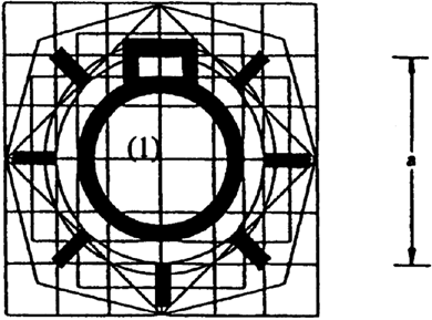 |
| Figure 16 Position (side) lamps Note: if the control is not separate, it may be identified by the symbol shown in figure 15. Tell-tale colour: green. | 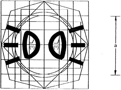 |
| Figure 17 ‘Gear box in neutral’ indicator Tell-tale colour: green. |  |
| Figure 18 Electric starter |  |
Appendix Structure of the model base for the symbols referred to in point 2.1.5

The model base consists of:
a base 50 mm square, this dimension being equal to nominal dimension ‘a’ in the original;
a base circle 56 mm in diameter having approximately the same area as the base square (1);
a second 50 mm-diameter circle is drawn within the base square (1);
a second square the tips of which lie on the base circle (2) and the sides of which are parallel to those of the base square (1);
two rectangles having the same area as the base square (1), their sides being at right angles to each other and each of them devised so as to divide the opposite sides of the base square into symmetrical points;
a third square the sides of which pass through the points of intersection of the base square (1) and the base circle (2) and are inclined at 45°, thus providing the greatest horizontal and vertical dimensions of the model base;
an irregular octagon formed by lines inclined at 30° to the sides of the square (7).
The base model is laid upon a grid the lower side of which measures 12,5 mm and coincides with the base square (1).
Options/Help
Print Options
PrintThe Whole Directive
PrintThis Annex only
Legislation is available in different versions:
Latest Available (revised):The latest available updated version of the legislation incorporating changes made by subsequent legislation and applied by our editorial team. Changes we have not yet applied to the text, can be found in the ‘Changes to Legislation’ area.
Original (As adopted by EU): The original version of the legislation as it stood when it was first adopted in the EU. No changes have been applied to the text.
Opening Options
Different options to open legislation in order to view more content on screen at once
More Resources
Access essential accompanying documents and information for this legislation item from this tab. Dependent on the legislation item being viewed this may include:
- the original print PDF of the as adopted version that was used for the EU Official Journal
- lists of changes made by and/or affecting this legislation item
- all formats of all associated documents
- correction slips
- links to related legislation and further information resources
More Resources
Use this menu to access essential accompanying documents and information for this legislation item. Dependent on the legislation item being viewed this may include:
- the original print PDF of the as adopted version that was used for the print copy
- correction slips
Click 'View More' or select 'More Resources' tab for additional information including:
- lists of changes made by and/or affecting this legislation item
- confers power and blanket amendment details
- all formats of all associated documents
- links to related legislation and further information resources
 All content is available under the Open Government Licence v3.0 except where otherwise stated. This site additionally contains content derived from EUR-Lex, reused under the terms of the Commission Decision 2011/833/EU on the reuse of documents from the EU institutions. For more information see the EUR-Lex public statement on re-use.