- Latest available (Revised)
- Original (As adopted by EU)
Commission Directive 2010/19/EUShow full title
Commission Directive 2010/19/EU of 9 March 2010 amending, for the purposes of adaptation to technical progress in the field of spray-suppression systems of certain categories of motor vehicles and their trailers, Council Directive 91/226/EEC, and Directive 2007/46/EC of the European Parliament and of the Council (Text with EEA relevance)
You are here:

What Version
Advanced Features
- Show Geographical Extent(e.g. England, Wales, Scotland and Northern Ireland)
- Show Timeline of Changes
More Resources
Revised version PDFs
- Revised 16/07/20111.20 MB
Legislation originating from the EU
When the UK left the EU, legislation.gov.uk published EU legislation that had been published by the EU up to IP completion day (31 December 2020 11.00 p.m.). On legislation.gov.uk, these items of legislation are kept up-to-date with any amendments made by the UK since then.


This item of legislation originated from the EU
Legislation.gov.uk publishes the UK version. EUR-Lex publishes the EU version. The EU Exit Web Archive holds a snapshot of EUR-Lex’s version from IP completion day (31 December 2020 11.00 p.m.).
Changes over time for: ANNEX I
Status:
EU Directives are published on this site to aid cross referencing from UK legislation. Since IP completion day (31 December 2020 11.00 p.m.) no amendments have been applied to this version.
ANNEX IU.K.
1.The list of Annexes to Directive 91/226/EEC is amended as follows:U.K.
(a)
the title relating to Appendix 3 of Annex II is replaced by the following:
‘Information document for EC component type-approval’;
(b)
the title relating to Annex III is replaced by the following:
‘Annex III
:
Requirements relating to the EC type approval of a vehicle with regard to the fitting of spray suppression systems
Appendix 1
:
Information document for EC vehicle type-approval
Appendix 2
:
Model for EC vehicle type-approval certificate’;
(c)
the line ‘FIGURES: (1 to 9)’ is replaced by the following:
‘Annex V
:
Figures 1 to 9’.
2.Annex I to Directive 91/226/EEC is amended as follows:U.K.
(a)
points 9, 10 and 11 are replaced by the following:
‘9. Retractable axle
“Retractable axle” means an axle as defined in Annex I point 2.15 to Directive 97/27/EC.
10. Unladen vehicle
“Unladen vehicle” means a vehicle in running order as defined in point 2.6 of Annex I to Directive 2007/46/EC of the European Parliament and of the Council(1).
11. Tread
“Tread” is the part of the tyre as defined in point 2.8 of Annex II to Directive 92/23/EEC.’;
(b)
the following points 13, 14 and 15 are added:
‘13. Semitrailer towing vehicle
“Semitrailer towing vehicle” means a towing vehicle as defined in point 2.1.1.2.2 of Annex I to Directive 97/27/EC.
14. Technically permissible maximum laden mass
“Technically permissible maximum laden mass” means the maximum mass of the vehicle as defined in point 2.6 of Annex I to Directive 97/27/EC.
15. Type of vehicle
“Type of vehicle” means, in relation to spray suppression complete, incomplete or completed vehicles, which do not differ with respect to the following aspects:
type of spray suppression device (installed on the vehicle),
manufacturer’s spray suppression system type designation.’
3.Annex II to Directive 91/226/EEC is amended as follows:U.K.
(a)
points 2 to 3.4.3 are replaced by the following:
‘2. Application for EC component type-approval
2.1.The application for EC component type-approval pursuant to Article 7 of Directive 2007/46/EC of a type of spray-suppression device shall be submitted by the manufacturer.
2.2.A model for the information document is set out in Appendix 3.
2.3.The following shall be submitted to the technical service responsible for conducting the type-approval tests:
Four samples: three of which for tests and a fourth to be kept by the laboratory for any subsequent verification. The test laboratory may require further samples.
2.4.Markings
Each sample must be clearly and indelibly marked with the trade name or mark and an indication of the type and include a space that is large enough for the EC component type-approval mark.
3. Granting of EC component type-approval
3.1.If the relevant requirements are satisfied, EC type-approval pursuant to Article 10 of Directive 2007/46/EC shall be granted.
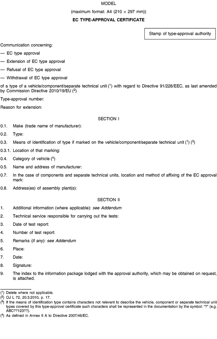
3.2.A model for the EC type-approval certificate is set out in Appendix 4.
3.3.An approval number in accordance with Annex VII to Directive 2007/46/EC shall be assigned to each type of spray-suppression device approved. The same Member State shall not assign the same number to another type of spray-suppression device.
3.4.Any spray-suppression device in conformity with a type approved pursuant to this Directive shall bear an EC component type-approval mark, so affixed as to be indelible and easily legible even when the device is fitted to the vehicle.
3.5.A symbol “A” for devices of the energy-absorption type or “S” for devices of the air/water separator type shall be added to the approval mark in accordance with point 1.3 of the Appendix of Annex VII to Directive 2007/46/EC.’;
(b)
Appendices 1 to 4 are replaced by the following:
‘Appendix 1U.K. Tests on spray-suppression devices of the energy-absorber type
1. Principle
The aim of this test is to quantify the ability of a device to retain the water directed against it by a series of jets. The test assembly is intended to reproduce the conditions under which the device is to function when fitted to a vehicle as regards the volume and speed of the water thrown up from the ground by the tyre tread.
2. Equipment
See Figure 8 in Annex V for a description of the test assembly.
3. Test conditions
3.1.The tests must be carried out in a closed room with a still-air environment.
3.2.The ambient temperature and the temperature of the test pieces must be 21 (± 3) °C.
3.3.De-ionized water is to be used.
3.4.The test pieces must be prepared for each test by wetting.
4. Procedure
4.1.Secure a 500 (+ 0/– 5) mm wide 750 mm high sample of the equipment to be tested to the vertical plate of the testing equipment, making sure that the sample lies well within the limits of the collector, and that no obstacle is able to deflect the water, either before or after its impact.
4.2.Set the water flow rate at 0,675 (+/– 0,01) l/s and direct at least 90 l, at most 120 l on to the sample from a horizontal distance of 500 (+/– 2) mm (Figure 8 of Annex V).
4.3.Allow the water to trickle from the sample into the collector. Calculate the percentage of water collected versus the quantity of water sprayed.
4.4.Carry out the test five times on the sample according to points 4.2 and 4.3. Calculate the average percentage of the series of five tests.
5. Results
5.1.The average percentage calculated in point 4.4 must be 70 % or higher.
5.2.If within a series of five tests the highest and lowest percentages of water collected depart from the average percentage by more than 5 %, the series of five tests must be repeated.
If within a second series of five tests the highest and lowest percentages of water recovered again depart from the average percentage by more than 5 % and if the lower value does not satisfy the requirements of point 5.1, type-approval shall be refused.
5.3.Test whether the vertical position of the device influences the results obtained. If it is the case, the procedure described in points 4.1 to 4.4 must be repeated in the positions giving the highest and lowest percentage of water collected; the requirements of point 5.2 remain in force.
The mean of the individual results shall then be taken to give the average percentage. this average percentage must be 70 or higher.
Appendix 2U.K. Test on spray-suppression devices of the air/water separator type
1. Principle
This test is intended to determine the effectiveness of a porous material intended to retain the water with which it has been sprayed by means of a pressurised air/water pulveriser.
The equipment used for the test must simulate the conditions to which the material would be submitted, with regard to the volume and speed of the water sprays produced by the tyres, if it were fitted to a vehicle.
2. Equipment
See figure 9 in Annex v for a description of the test assembly.
3. Test conditions
3.1.The tests must be carried out in a closed room with a still-air environment.
3.2.The ambient temperature and the temperature of the test pieces must be 21 (± 3) °C.
3.3.De-ionized water must be used.
3.4.The test pieces must be prepared for each test by wetting
4. Procedure
4.1.Secure a 305 × 100 mm sample vertically in the test assembly, check that there is no space between the sample and the upper curved plate and that the tray is properly in position. Fill the pulveriser tank with 1 ± 0,005 litres of water and place this as described in the diagram.
4.2.The pulveriser must be regulated as follows:
pressure (at pulveriser): 5 bar + 10 %/– 0 %
flowrate: 1 litre/minute ± 5 seconds
pulverisation: circular, 50 ± 5 mm in diameter at 200 ± 5 mm from the sample, nozzle 5 ± 0,1 mm in diameter.
4.3.Pulverise until there is no more water mist and note the time taken. Let the water flow out of the sample on to the tray for 60 seconds and measure the volume of water collected. Measure the quantity of water left in the pulveriser tank. Calculate the percentage by volume of water collected versus the volume of water pulverised.
4.4.Carry out the test five times and calculate the average percentage of the quantity collected. Check before each test that the tray, pulveriser tank and measuring vessel are dry.
5. Results
5.1.The average percentage calculated in point 4.4 must be 85 % or higher.
5.2.If within a series of five tests the highest and lowest percentages of water collected depart from the average percentage by more than 5 %, the series of five tests must be repeated. If within a second series of five tests the highest and lowest percentages of water recovered again depart from the average percentage by more than 5 %, and if the lower value does not satisfy the requirements of point 5.1, type-approval shall be refused.
5.3.Where the vertical position of the device influences the results obtained, the procedure described in points 4.1 to 4.4 must be repeated in the positions giving the highest and lowest percentages of water collected; the requirements of point 5.2 remain in force.
The requirement of point 5.1 remains in force in order to give the results of each test.
Appendix 3U.K.Information document No … relating to the EC component type-approval of spray suppression devices (Directive 91/226/EEC)
The following information, if applicable, must be supplied in triplicate and include a list of contents. Any drawings must be supplied in appropriate scale and in sufficient detail on size A4 or on a folder of A4 format. Photographs, if any, must show sufficient detail.
If the systems, components or separate technical units have electronic controls, information concerning their performance must be supplied.
0.GENERAL
0.1.Make (trade name of manufacturer):
0.2.Type:
0.5.Name and address of manufacturer:
0.7.In the case of components and separate technical units, location and method of affixing of the EC approval mark:
0.8.Address(es) of assembly plant(s):
1.DESCRIPTION OF THE DEVICE
1.1.A technical description of the spray-suppression device indicating its physical operating principle and the relevant test to which it must be subject:
1.2.The materials used:
1.3.Drawing(s) in sufficient detail and to an appropriate scale to enable this (or these) to be identified. The drawing must show the space intended for the EEC component type-approval mark:
Date
Signed
Appendix 4U.K.
‘AddendumU.K.to EC type-approval certificate No … concerning the component type-approval of spray suppression devices with regard to Directive 91/226/EEC as last amended by Directive 2010/19/EU
1.Additional information
1.1.Operating principle of device: energy-absorption/air/water separator(2):
1.2.Characteristics of spray-suppression devices (brief description, trademark or name, number(s):
5.Remarks (if any):’’
4.Annex III to Directive 91/226/EEC is amended as follows:U.K.
(a)
points 0.1 and 0.2 are replaced by the following:
‘SCOPE
0.1.Category N and O vehicles, with the exception of off-road vehicles as defined in Annex II to Directive 2007/46/EC, shall be constructed and/or fitted with spray suppression systems in such a way as to meet the requirements laid down in this Annex. In case of chassis/cab vehicles, these requirements may only be applied to the wheels covered by the cab.
For vehicles of category N1 and N2 with a permissible maximum laden mass not exceeding 7,5 tonnes, the requirements of Directive 78/549/EEC(3) may be applied as alternative to the requirements of this Directive at the request of the manufacturer.
0.2.The requirements of this Annex relating to spray-suppression devices, as defined in point 4 of Annex I, are not mandatory for categories N, O1 and O2 vehicles with a permissible maximum laden mass not exceeding 7,5 tonnes, chassis/cab vehicles, unbodied vehicles or vehicles on which the presence of spray-suppression devices would be incompatible with their use. However, if such devices are fitted to those vehicles, they must conform to the requirements of this Directive.’;
(b)
point 4 is replaced by the following:
‘4. Position of outer valance
The distance “c” between the longitudinal plane tangential to the outer tyre wall, apart from any tyre bulge near the ground, and the inner edge of the valance must not exceed 100 mm (Figures 1a and 1b of Annex V).’;
(c)
points 4.1 and 4.2 are deleted;
(d)
point 7.1.1 is replaced by the following:
‘7.1.1.
The mudguards must cover the zone immediately above, ahead and behind the tyre or tyres in the following manner:
(a)
in the case of a single or multiple axle, the forward edge (C) must extend forwards to reach a line O-Z where θ (theta) is no more than 45° above the horizontal.
The rearmost edge (Figure 2 of Annex V) must extend downwards in such a way as not to be more than 100 mm above a horizontal line passing through the centre of the wheel;
(b)
in the case of multiple axles the angle θ relates only to the foremost axle and the requirement relating to the height of the rearmost edge applies only to the rearmost axle;
(c)
the mudguard must possess a total width “q” (Figure 1a of Annex V) at least adequate to cover the width of the tyre “b” or the entire width of two tyres “t” in the case of twin wheels, account being taken of the extremes for the tyre/wheel unit specified by the manufacturer. Dimensions “b” and “t” shall be measured at hub height, excluding any markings, ribs, protective bands, etc., on the tyre walls.’;
(e)
point 7.1.3 is replaced by the following:
‘7.1.3.
If the mudguards are made up of several components, when fitted, they must not incorporate any aperture enabling spray to exit while the vehicle is in motion. This requirement is deemed to be met if, when the vehicle is either laden or unladen, any radial jet running outwards from the wheel centre over the entire width of the tyre running surface and within the range covered by the mudguard always strikes against a part of the spray suppression system.’;
(f)
points 7.2.1, 7.2.2 and 7.2.3 are replaced by the following:
‘7.2.1.
In the case of single axles, the lower edge of the outer valance may not be situated beyond the following distances and radii, as measured from the centre of the wheel, except at the lowest extremities that may be rounded (Figure 2 of Annex V).
Air suspension:
Mechanical suspension
(a)
general case } Rv ≤ 1,8 R
(b)
non-steered wheels for vehicles with a technically permissible laden mass more than 7,5 t } Rv ≤ 1,5 R
where R is the radius of the tyre fitted to the vehicle, and Rv the distance, expressed as a radius, at which the lower edge of the outer valance is situated.
7.2.2.
In the case of multiple axles the requirements laid down in point 7.2.1 do not apply between the vertical transversal planes passing through the centre of the first and the last axles where the outer valance may be straight in order to ensure the continuity of the spray suppression system. (Figure 4 of Annex V).
7.2.3.
The distance between the uppermost and the lowermost points of the spray suppression system (mudguard and outer valance) measured in any cross section perpendicular to the mudguard (see figures 1b and 2 in Annex V) must extend to not less than 45 mm at all points behind a vertical line passing through the centre of the wheel or the first wheel in the case of multiple axles. This dimension may be gradually reduced in front of this line.’;
(g)
the following points 7.2.5 and 7.2.6 are inserted:
‘7.2.5.
The requirements of points 7.2.3 and 7.2.4 may not be respected locally when the valance is composed by different elements with relative movement.
7.2.6.
Tractors for semi-trailers with a low chassis (defined in point 6.20 of standard ISO 612 of 1978), namely those which may have a coupling pin height in relation to the ground equal to or less than 1 100 mm, may be designed in such a way as to be exempted from the requirements of points 7.1.1.a, 7.1.3 and 7.2.4. In this regard, mudguards and valances may not cover the area immediately above the tyres of the rear axles, when these tractors are coupled to a semi-trailer, in order to avoid the spray-suppression system being destroyed. However, the mudguards and valances of these vehicles must conform to the requirements of the above points, in sectors more than 60° from the vertical line passing through the centre of the wheel, in front and behind these tyres.
Those vehicles must therefore be designed in such a way as to meet the requirements set out in the first paragraph when they are operated without a semi-trailer.
In order to be able to meet those requirements, mudguards and valances may, for example, comprise a removable part.’;
(h)
point 7.3.1 is replaced by the following:
‘7.3.1.
The width of the flap must fulfil the requirement for “q” in point 7.1.1(c), except where the flap is within the mudguards, in which case it must be at least equal in width to the tread of the tyre.
The width of the part of the rain flaps positioned beneath the mudguard must satisfy the condition laid down in this paragraph with a tolerance of 10 mm at each side.’;
(i)
point 7.3.3 is replaced by the following:
‘7.3.3.
The maximum height of the bottom edge must not exceed 200 mm (Figure 3 of Annex V).
This distance is increased to 300 mm in the case of the last axle where the radial distance of the lower edge of the outer valancing, Rv, does not exceed the dimensions of the radius of the tyres fitted to the wheels on that axle.
The maximum height of the bottom edge of the rain flap in relation to the ground, may be raised to 300 mm if the manufacturer deems it technically appropriate with regard to the suspension characteristics.’;
(j)
in point 7.3.5, the reference to ‘Figure 4b’ is replaced by a reference to ‘Figure 4 of Annex V’;
(k)
point 9.3.2.1 is replaced by the following:
‘9.3.2.1.
The lower edge of the spray-suppression device must be not more than 200 mm from the ground.
The maximum height of the bottom edge of the rain flap in relation to the ground, may be raised to 300 mm if the manufacturer deems it technically appropriate with regard to the suspension characteristics.’;
(l)
the following point 10 is added:
‘10.
In the case of multiple axles, the spray-suppression system of one axle, which is not the furthest back, may not need to cover the entire width of the tread of the tyre when there is, locally, the possibility of interference between the spray-suppression system and the structure of the axles or of the suspension or of the undercarriage.’;
(m)
the Appendix is deleted;
(n)
the following Appendices 1 and 2 are added:
‘Appendix 1U.K.INFORMATION DOCUMENT No … RELATING TO EC TYPE-APPROVAL OF A VEHICLE WITH RESPECT TO THE FITTING OF SPRAY-SUPPRESSION SYSTEMS (DIRECTIVE 91/226/EEC, AS LAST AMENDED BY DIRECTIVE 2010/19/EU)(4) (For the Explanatory notes please refer to Annex I to Directive 2007/46/EC)
The following information, if applicable, must be supplied in triplicate and include a list of contents. Any drawings must be supplied in appropriate scale and in sufficient detail on size A4 or on a folder of A4 format. Photographs, if any, must show sufficient detail.
If the systems, components or separate technical units have electronic controls, information concerning their performance must be supplied.
0.GENERAL
0.1.Make (trade name of manufacturer):
0.2.Type:
0.2.1.Commercial name(s) (if available):
0.3.Means of identification of type, if marked on the vehicle (b)
0.3.1.Location of that marking:
0.4.Category of vehicle (c):
0.5.Name and address of manufacturer:
0.8.Address(es) of assembly plant(s):
1.GENERAL CONSTRUCTION CHARACTERISTICS OF THE VEHICLE
1.1.Photographs and/or drawings of a representative vehicle:
1.3.Number of axles and wheels:
1.3.1.Number and position of axles with twin wheels:
1.3.2.Number and position of steered axles
2.MASSES AND DIMENSIONS (f) (g)
(in kg and mm) (Refer to drawing where applicable)
2.1.Wheelbase(s) (fully loaded) (g) (l):
2.6.Mass in running order (maximum and minimum for each variant)
Mass of the vehicle with bodywork and, in the case of a towing vehicle of category other than M1, with coupling device, if fitted by manufacturer, in running order, or mass of the chassis or chassis with cab, without bodywork and/or coupling device if the manufacturer does not fit the bodywork and/or coupling device (including liquids, tools, spare wheel, if fitted, and driver and, for buses and coaches, a crew member if there is a crew seat in the vehicle) (h) (maximum and minimum for each variant):
2.6.1.Distribution of this mass among the axles and, in the case of a semi-trailer or centre-axle trailer, load on the coupling point (maximum and minimum for each variant):
2.8.Technically permissible maximum laden mass stated by the manufacturer (i) (3):
9.BODYWORK
9.20.Spray-suppression system
9.20.0.Presence: yes/no/incomplete (1)
9.20.1.Brief description of the vehicle with regard to its spray-suppression system and the constituent components:
9.20.2.Detailed drawings of the spray-suppression system and its position on the vehicle showing the dimensions specified in the Figures in Annex V to Directive 91/226/EEC and taking account of the extremes of tyre/wheel combinations:
9.20.3.Approval number(s) of spray-suppression device(s), if available:
Date, File
Appendix 2U.K.

‘AddendumU.K.TO EC TYPE-APPROVAL CERTIFICATE No … CONCERNING THE TYPE APPROVAL OF A VEHICLE WITH REGARD TO DIRECTIVE 91/226/EEC AS LAST AMENDED BY DIRECTIVE 2010/19/EU
1.Additional information
1.1.Characteristics of the spray-suppression devices (type, brief description, trade mark or name, component type-approval number(s):
5.Remarks (if any):’’’
(2)
Delete where not applicable.’
(4)
For vehicles of category N1 and those of category N2 with a technically permissible maximum laden mass not exceeding 7,5 tons using the derogation of point 0.1 of Annex III to this Directive, the information document set out in Annex II to Directive 78/549/EEC may be used.
Options/Help
Print Options
PrintThe Whole Directive
PrintThis Annex only
Legislation is available in different versions:
Latest Available (revised):The latest available updated version of the legislation incorporating changes made by subsequent legislation and applied by our editorial team. Changes we have not yet applied to the text, can be found in the ‘Changes to Legislation’ area.
Original (As adopted by EU): The original version of the legislation as it stood when it was first adopted in the EU. No changes have been applied to the text.
See additional information alongside the content
Geographical Extent: Indicates the geographical area that this provision applies to. For further information see ‘Frequently Asked Questions’.
Show Timeline of Changes: See how this legislation has or could change over time. Turning this feature on will show extra navigation options to go to these specific points in time. Return to the latest available version by using the controls above in the What Version box.
Opening Options
Different options to open legislation in order to view more content on screen at once
More Resources
Access essential accompanying documents and information for this legislation item from this tab. Dependent on the legislation item being viewed this may include:
- the original print PDF of the as adopted version that was used for the EU Official Journal
- lists of changes made by and/or affecting this legislation item
- all formats of all associated documents
- correction slips
- links to related legislation and further information resources
Timeline of Changes
This timeline shows the different versions taken from EUR-Lex before exit day and during the implementation period as well as any subsequent versions created after the implementation period as a result of changes made by UK legislation.
The dates for the EU versions are taken from the document dates on EUR-Lex and may not always coincide with when the changes came into force for the document.
For any versions created after the implementation period as a result of changes made by UK legislation the date will coincide with the earliest date on which the change (e.g an insertion, a repeal or a substitution) that was applied came into force. For further information see our guide to revised legislation on Understanding Legislation.
More Resources
Use this menu to access essential accompanying documents and information for this legislation item. Dependent on the legislation item being viewed this may include:
- the original print PDF of the as adopted version that was used for the print copy
- correction slips
Click 'View More' or select 'More Resources' tab for additional information including:
- lists of changes made by and/or affecting this legislation item
- confers power and blanket amendment details
- all formats of all associated documents
- links to related legislation and further information resources
 All content is available under the Open Government Licence v3.0 except where otherwise stated. This site additionally contains content derived from EUR-Lex, reused under the terms of the Commission Decision 2011/833/EU on the reuse of documents from the EU institutions. For more information see the EUR-Lex public statement on re-use.