- Latest available (Revised)
- Point in Time (27/07/2017)
- Original (As adopted by EU)
Commission Regulation (EU) No 582/2011Show full title
Commission Regulation (EU) No 582/2011 of 25 May 2011 implementing and amending Regulation (EC) No 595/2009 of the European Parliament and of the Council with respect to emissions from heavy duty vehicles (Euro VI) and amending Annexes I and III to Directive 2007/46/EC of the European Parliament and of the Council (Text with EEA relevance)
You are here:

What Version
Advanced Features
- Show Geographical Extent(e.g. England, Wales, Scotland and Northern Ireland)
- Show Timeline of Changes
More Resources
Revised version PDFs
- Revised 01/09/20202.26 MB
- Revised 15/12/20192.14 MB
- Revised 22/07/20181.82 MB
- Revised 18/01/20181.82 MB
- Revised 27/07/20171.81 MB
- Revised 01/01/20171.81 MB
- Revised 17/10/20161.79 MB
- Revised 03/07/20141.83 MB
- Revised 05/03/20141.84 MB
- Revised 01/07/20133.92 MB
- Revised 03/02/20123.91 MB
Legislation originating from the EU
When the UK left the EU, legislation.gov.uk published EU legislation that had been published by the EU up to IP completion day (31 December 2020 11.00 p.m.). On legislation.gov.uk, these items of legislation are kept up-to-date with any amendments made by the UK since then.


This item of legislation originated from the EU
Legislation.gov.uk publishes the UK version. EUR-Lex publishes the EU version. The EU Exit Web Archive holds a snapshot of EUR-Lex’s version from IP completion day (31 December 2020 11.00 p.m.).
Changes over time for: Appendix 3
Status:
Point in time view as at 27/07/2017.
Changes to legislation:
There are outstanding changes not yet made to Commission Regulation (EU) No 582/2011. Any changes that have already been made to the legislation appear in the content and are referenced with annotations.
Changes to Legislation
Changes and effects yet to be applied by the editorial team are only applicable when viewing the latest version or prospective version of legislation. They are therefore not accessible when viewing legislation as at a specific point in time. To view the ‘Changes to Legislation’ information for this provision return to the latest version view using the options provided in the ‘What Version’ box above.
[F1Appendix 3
Textual Amendments
F1 Substituted by Commission Regulation (EU) 2016/1718 of 20 September 2016 amending Regulation (EU) No 582/2011 with respect to emissions from heavy-duty vehicles as regards the provisions on testing by means of portable emission measurement systems (PEMS) and the procedure for the testing of the durability of replacement pollution control devices (Text with EEA relevance).
Durability procedure for evaluation of emissions performance of a replacement pollution control device U.K.
1. This Appendix sets out the durability procedure referred to in point 4.3.2.4 of Annex XI, for the purpose of evaluating the emissions performance of a replacement pollution control device. U.K.
2. DESCRIPTION OF THE DURABILITY PROCEDURE U.K.
2.1. The durability procedure shall consist of a data collection phase and a service accumulation schedule. U.K.
2.2. Data collection phase U.K.
2.2.1. The selected engine, equipped with the complete exhaust after-treatment system incorporating the replacement pollution control device, shall be cooled down to ambient temperature and run one cold start WHTC test-cycle in accordance with paragraphs 7.6.1 and 7.6.2 of Annex 4 to UN/ECE Regulation No 49. U.K.
2.2.2. Immediately after the cold start WHTC test-cycle, the engine shall be run for nine consecutive hot start WHTC test-cycles in accordance with paragraph 7.6.4 of Annex 4 to UN/ECE Regulation No 49. U.K.
2.2.3. The test sequence set out in points 2.2.1 and 2.2.2 shall be carried out in accordance with the instructions laid down in paragraph 7.6.5 of Annex 4 to UN/ECE Regulation No 49. U.K.
2.2.4. Alternatively, the relevant data can be collected by driving a fully loaded vehicle equipped with the selected exhaust after-treatment system incorporating the replacement pollution control device. The test can be carried out either on the road following the trip requirements of points 4.5 to 4.5.5 of Annex II to this Regulation with comprehensive recording of the driving data, or on a suitable chassis dynamometer. If an on-road test is chosen, the vehicle shall be driven over a cold test-cycle, as set out in Appendix 5 to this Annex, followed by nine hot test-cycles, identical to the cold one, in a way that the work developed by the engine is the same as the one achieved under points 2.2.1 and 2.2.2. If a chassis dynamometer is chosen, the simulated road gradient of the test-cycle in Appendix 5 shall be adapted to match the work developed by the engine over the WHTC. U.K.
2.2.5. The type-approval authority shall refuse the temperature data obtained under point 2.2.4 if it deems those data to be unrealistic and shall request either the repetition of the test, or the carrying out of a test pursuant to points 2.2.1, 2.2.2 and 2.2.3. U.K.
2.2.6. Temperatures in the replacement pollution control device shall be recorded during the whole test sequence, at the location with the highest temperature. U.K.
2.2.7. In cases where the location with the highest temperature varies over time, or where that location is difficult to define, multiple bed temperatures should be recorded at suitable locations. U.K.
2.2.8. The number and locations of the temperature measurements shall be selected by the manufacturer, in agreement with the type-approval authority, based on best engineering judgement. U.K.
2.2.9. With the agreement of the type-approval authority, a single catalyst bed temperature or the catalyst inlet temperature may be used if measuring multiple bed temperatures is proven to be unfeasible or too difficult. U.K.


2.2.10. The temperatures shall be measured and recorded at a minimum rate of once every second (1 Hz) during the test sequence. U.K.
2.2.11. The measured temperatures shall be tabulated into a histogram with temperature bins no larger than 10 °C. In the case mentioned in point 2.2.7, the highest temperature each second shall be the one recorded in the histogram. Each bar of the histogram shall represent the cumulated frequency in seconds of the measured temperatures falling in the specific bin. U.K.
2.2.12. The time in hours corresponding to each temperature bin must be determined and then extrapolated to the useful life of the replacement pollution control device, in accordance with the values specified in Table 1. The extrapolation shall be based on the assumption that one WHTC cycle corresponds to 20 km driving. U.K.
Table 1
Useful life of the replacement pollution control device for each vehicle category, and equivalent WHTC test-cycles and hours of operation
| Vehicle category | Mileage (km) | Equivalent number of WHTC test-cycles | Equivalent number of hours |
|---|---|---|---|
| Engine systems fitted to vehicles of category M 1 , N 1 and N 2 | 114 286 | 5 714 | 2 857 |
| Engine systems fitted to vehicles of category N 2 , N 3 with a maximum technically permissible mass not exceeding 16 tonnes and M 3 Class I, Class II and Class A, and Class B with a maximum technically permissible mass exceeding 7,5 tonnes | 214 286 | 10 714 | 5 357 |
| Engine systems fitted to vehicles of category N 3 with a maximum technically permissible mass exceeding 16 tonnes, and M 3 , Class III and Class B with a maximum technically permissible mass exceeding 7,5 tonnes | 500 000 | 25 000 | 12 500 |
2.2.13. It is allowed to perform the data collection phase for different devices at the same time. U.K.
2.2.14. In the case of systems operating in the presence of active regeneration, the number, length and temperatures of the regenerations occurring during the test sequence defined in points 2.2.1 and 2.2.2 shall be recorded. If no active regeneration has occurred, the hot sequence defined in point 2.2.2 shall be extended in order to include at least two active regenerations. U.K.
2.2.15. The total lubricant consumed during the data collection period, in g/h, shall be recorded, using any suitable method, as for example the drain and weigh procedure described in Appendix 6. For this purpose, the engine shall be run during 24 hours, performing consecutive WHTC test-cycles. In cases where an accurate measurement of oil consumption cannot be obtained, the manufacturer, in agreement with the type-approval authority, may use the following options for the determination of the lubricant consumption: U.K.
(a)
a default value of 30 g/h;
(b)
a value requested by the manufacturer, based on sound data and information, and agreed with the type-approval authority.
2.3. Calculation of the equivalent ageing time corresponding to a reference temperature U.K.
2.3.1. The temperatures recorded pursuant to points 2.2 to 2.2.15 shall be reduced to a reference temperature T r , requested by the manufacturer in agreement with the type-approval authority, within the range of the temperatures recorded during the data collection phase. U.K.
2.3.2. In the case specified in point 2.2.13, the value of T r for each one of the devices may vary. U.K.
2.3.3. The equivalent ageing time corresponding to the reference temperature shall be calculated, for each bin referred to in 2.2.11, in accordance with the following equation: U.K.
Equation 1:
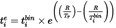
Where:
R
=
thermal reactivity of the replacement pollution control device.
The following values shall be used:
Diesel oxidation catalyst (DOC): 18 050
Catalysed DPF: 18 050
SCR or ammonia oxidation catalyst (AMOX) based on iron-zeolite (Fe-Z): 5 175
SCR copper-zeolite (Cu-Z): 11 550
SCR Vanadium (V): 5 175
LNT (lean-NO x trap): 18 050
T r
=
reference temperature, in K .

=
mid-point temperature, in K , of the temperature bin i to which the replacement pollution control device is exposed during the data collection phase, registered in the temperature histogram.

=
the time, in hours, corresponding to the temperature 


=
the equivalent ageing time, in hours, needed to achieve, by exposing the replacement pollution control device at the temperature T r , the same amount of ageing as the one that would result from exposure of the replacement pollution control device at the temperature 

i
=
bin number, where 1 is number for the bin with the lowest temperature and n the value for the bin with the highest temperature.
2.3.4. The total equivalent ageing time shall be calculated in accordance with the following equation: U.K.
Equation 2:

Where:
AT
=
total equivalent ageing time, in hours, needed to achieve, by exposing the replacement pollution control device at the temperature T r , the same amount of ageing as the one that would result from exposure of the replacement pollution control device, over its useful life, to the temperature 


=
the equivalent ageing time, in hours, needed to achieve, by exposing the replacement pollution control device at the temperature T r , the same amount of ageing as the one that would result from exposure of the replacement pollution control device at the temperature 

i
=
bin number, where 1 is number for the bin with the lowest temperature and n the value for the bin with the highest temperature.
n
=
Total number of temperature bins.
2.3.5. In the case referred to in point 2.2.13, AT shall be calculated for each device. U.K.
2.4. Service accumulation schedule U.K.
2.4.1. General requirements U.K.
2.4.1.1. The service accumulation schedule shall allow acceleration of the ageing of the replacement pollution control device, using the information gathered during the data collection phase set out in point 2.2. U.K.
2.4.1.2. The service accumulation schedule shall consist of a thermal accumulation schedule and a lubricant consumption accumulation schedule in accordance with point 2.4.4.6. The manufacturer, in agreement with the type-approval authority, may not have to carry out a lubricant consumption accumulation schedule in case the replacement pollution control devices are placed downstream of an after-treatment filter component (e.g. diesel particulate filter). Both the thermal accumulation schedule and the lubricant consumption accumulation schedule shall consist of a repetition of, respectively, a series of thermal and lubricant consumption sequences. U.K.
2.4.1.3. In the case of replacement pollution control devices operating in the presence of active regeneration, the thermal sequence shall be complemented with an active regeneration mode. U.K.
2.4.1.4. For service accumulation schedules consisting of both thermal and lubricant consumption accumulation schedules, their respective sequences shall be alternated, so that for each thermal sequence that has to be performed, the following sequence corresponds to lubricant consumption. U.K.
2.4.1.5. It is allowed to perform the service accumulation schedule at the same time for different devices. In that case, a single service accumulation schedule shall be set for all the devices. U.K.
2.4.2. Thermal accumulation schedule U.K.
2.4.2.1. The thermal accumulation schedule shall simulate the effect of thermal ageing on the performance of a replacement pollution control device until the end of its lifetime. U.K.
2.4.2.2. The engine used for the performance of the service accumulation schedule, fitted with the exhaust after-treatment system incorporating the replacement pollution control device, is operated for a minimum of three consecutive thermal sequences, as set out in Appendix 4. U.K.
2.4.2.3. The temperatures shall be recorded over a minimum of two thermal sequences. The first sequence, conducted for warming up, shall not be taken into account for the purpose of temperature gathering. U.K.
2.4.2.4. The temperatures shall be recorded at suitable locations, chosen in accordance with points 2.2.6 to 2.2.9, at a minimum rate of once every second (1 Hz). U.K.
2.4.2.5. The effective ageing time corresponding to the thermal sequences referred to in point 2.4.2.3, shall be calculated in accordance with the following equations: U.K.
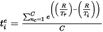

Where:

=
the effective ageing time, in hours, needed to achieve, by exposing the replacement pollution control device at the temperature T r , the same amount of ageing as the one that would result from exposure of the replacement pollution control device at the temperature T i during the second i .
T i
=
the temperature, in K , measured in the second i , in each one of the thermal sequences.
R
=
thermal reactivity of the replacement pollution control device. The manufacturer shall agree with the type-approval authority on the R value to be used. It will also be possible, as alternative, to use the following default values:
Diesel oxidation catalyst (DOC): 18 050 .
Catalysed DPF: 18 050
SCR or ammonia oxidation catalyst (AMOX) based on iron-zeolite (Fe-Z): 5 175
SCR copper-zeolite (Cu-Z): 11 550
SCR Vanadium (V): 5 175
LNT (lean-NO x trap): 18 050
T r
=
reference temperature, in K , being the same value as in equation 1.
AE
=
Effective ageing time, in hours, needed to achieve, by exposing the replacement pollution control device at the temperature T r , the same amount of ageing as the one that would result from exposure of the replacement pollution control device during the duration of the thermal sequence.
AT
=
total equivalent ageing time, in hours, needed to achieve, by exposing the replacement pollution control device at the temperature T r , the same amount of ageing as the one that would result from exposure of the replacement pollution control device, over its useful life, to the temperature 

i
=
number of temperature measurement.
p
=
total number of temperature measurements.
n c
=
thermal sequence number, of those conducted for the purpose of temperature gathering, in accordance with point 2.4.2.3.
C
=
total number of thermal sequences conducted for the purpose of temperature gathering.
2.4.2.6. The total number of thermal sequences to be included in the service accumulation schedule shall be determined by applying the following equation: U.K.
Equation 5:
N TS = AT/AE
Where:
N TS
=
total number of thermal sequences to be carried out during the service accumulation schedule
AT
=
total equivalent ageing time, in hours, needed to achieve, by exposing the replacement pollution control device at the temperature T r , the same amount of ageing as the one that would result from exposure of the replacement pollution control device, over its useful life, to the temperature 

AE
=
Effective ageing time, in hours, needed to achieve, by exposing the replacement pollution control device at the temperature T r , the same amount of ageing as the one that would result from exposure of the replacement pollution control device during the duration of the thermal sequence.
2.4.2.7. It is allowed to reduce N TS and, consequently the service accumulation schedule, by increasing the temperatures at which each device is exposed at each mode of the ageing cycle through the application of one or several of the following measures: U.K.
(a)
insulating the exhaust pipe;
(b)
moving the replacement pollution control device closer to the exhaust manifold;
(c)
artificially heating up the temperature of the exhaust;
(d)
optimising the engine settings without substantially changing the emission behaviour of the engine.
2.4.2.8. When applying the measures referred to in points 2.4.4.6 and 2.4.4.7, the total ageing time calculated from N TS shall not be less than 10 % of the useful life listed in Table 1, e.g. the vehicle category N 1 shall not have an N TS of less than 286 thermal sequences, assuming that each sequence is 1 hour long. U.K.
2.4.2.9. It is allowed to increase N TS and, consequently, the duration of the service accumulation schedule, by lowering the temperatures at each mode of the ageing cycle through the application of one or several of the following measures: U.K.
(a)
moving the replacement pollution control device further away from the exhaust manifold;
(b)
artificially cooling down the temperature of the exhaust;
(c)
optimising the engine settings.
2.4.2.10. In the case referred to in point 2.4.1.5, the following shall apply: U.K.
2.4.2.10.1.
N TS shall be the same for each device, so that a single service accumulation schedule can be set up.
2.4.2.10.2.
In order to achieve the same N TS for each device, a first N TS value shall be calculated for each device, with its own AT and AE values.
2.4.2.10.3.
If the calculated N TS values are different, one or more of the measures set out in points 2.4.2.7 to 2.4.2.10 may be applied on the device or devices for which N TS needs to be modified, over the thermal sequences referred to in point 2.4.2.3, in order to influence the measured T i and therefore conveniently speed up or slow down the artificial ageing of the targeted device or devices.
2.4.2.10.4.
The new N TS values corresponding to the new temperatures T i obtained in point 2.4.2.10.3 shall be calculated.
2.4.2.10.5.
The steps set out in points 2.4.2.10.3 and 2.4.2.10.4 shall be repeated until the N TS values obtained for each device in the system match.
2.4.2.10.6.
The T r values used for obtaining the different N TS in points 2.4.2.10.4 and 2.4.2.10.5 shall be the same ones as those used in points 2.3.2 and 2.3.5 for calculating AT for each device.
2.4.2.11. In the case of an assembly of replacement pollution control devices constituting a system within the meaning of Article 3(25) of Directive 2007/46/EC, one of the following two options may be considered for the thermal ageing of the devices: U.K.
2.4.2.11.1.
The devices within the assembly may be either separately or jointly aged, in accordance with point 2.4.2.10.
2.4.2.11.2.
If the assembly is built in such a way that it is not possible to decouple the devices (e.g. DOC + SCR in a can), the thermal ageing of the assembly shall be carried out with the highest N TS .
2.4.3. Modified thermal accumulation schedule for devices operating in the presence of active regeneration U.K.
2.4.3.1. The modified thermal accumulation schedule for devices operating in the presence of active regeneration shall simulate the effect of ageing due to both thermal load and active regeneration on a replacement pollution control device at the end of its lifetime. U.K.
2.4.3.2. The engine used for the service accumulation schedule, fitted with the exhaust after-treatment system incorporating the replacement pollution control device, is operated for a minimum of three modified thermal sequences, consisting each sequence of a thermal sequence as set out in Appendix 4, followed by a complete active regeneration, during which the peak temperature reached in the after-treatment system should be not lower than the peak temperature recorded in the data collection phase. U.K.
2.4.3.3. The temperatures shall be recorded over a minimum of two modified thermal sequences. The first sequence, conducted for warming up, shall not be taken into account for the purpose of temperature gathering. U.K.
2.4.3.4. In order to minimise the time elapsed between the thermal sequence as set out in Appendix 4 and the subsequent active regeneration, the manufacturer may artificially trigger the active regeneration by running, after each thermal sequence as set out in Appendix 4, the engine at a steady mode that enables a high production of soot by the engine. In that case, the steady mode shall also be considered as part of the modified thermal sequence set out in point 2.4.3.2. U.K.
2.4.3.5. The effective ageing time corresponding to each modified thermal sequence shall be calculated using equations 3 and 4. U.K.
2.4.3.6. The total number of modified thermal sequences to be conducted during the service accumulation schedule shall be calculated using equation 5. U.K.
2.4.3.7. It is allowed to reduce N TS , and consequently the duration of the service accumulation schedule, by increasing the temperatures at each mode of the modified thermal sequence, applying one or several of the measures set out in point 2.4.2.7. U.K.
2.4.3.8. In addition to the measures referred to in point 2.4.3.7, N TS can also be reduced by increasing the peak temperature of the active regeneration within the modified thermal sequence, without exceeding a bed temperature of 800 °C under any circumstances. U.K.
2.4.3.9. N TS shall never be less than 50 % of the number of active regenerations to which the replacement pollution control device is subjected during its useful life, calculated in accordance with the following equation: U.K.
Equation 5:

Where:
N AR
=
number of active regeneration sequences over the useful life of the replacement pollution control device.
t WHTC
=
equivalent number of hours corresponding to the vehicle category for which the replacement pollution control device is intended, obtained from Table 1.
t AR
=
duration, in hours, of an active regeneration.
t BAR
=
time, in hours, between two consecutive active regenerations.
2.4.3.10. If, as consequence of the application of the minimum number of modified thermal sequences as set out in point 2.4.3.9, AE × N TS calculated using equation 4 exceeds the AT calculated using equation 2, the time of each mode of the thermal sequence set out in Appendix 4, and embedded in the modified thermal sequence as set out in point 2.4.3.2, may be reduced in the same proportion, in order to make AE × N TS = AT . U.K.
2.4.3.11. It is allowed to increase N TS and consequently the duration of the service accumulation schedule, by lowering the temperatures at each mode of the thermal-active regeneration sequence by applying one or several of the measures set out in point 2.4.2.9. U.K.
2.4.3.12. In the case referred to in point 2.4.1.5, points 2.4.2.10 and 2.4.2.11 shall apply U.K.
2.4.4. Lubricant consumption accumulation schedule U.K.
2.4.4.1. The lubricant consumption accumulation schedule shall simulate the effect of ageing due to chemical poisoning or deposit formation as a result of lubricant consumption, on the performance of a replacement pollution control device at the end of its lifetime. U.K.
2.4.4.2. The lubricant consumed, in g/h, shall be determined over a minimum of 24 thermal sequences or a corresponding number of modified thermal sequences, using any suitable method, as for example the drain and weigh procedure described in Appendix 6. Fresh lubricant shall be used. U.K.
2.4.4.3. The engine shall be equipped with a constant volume oil sump in order to avoid the need of ‘ top-offs ’ , since oil level influences the oil consumption rate. Any suitable method, as for example the one described in the ASTM standard D7156-09, may be used. U.K.
2.4.4.4. The theoretical time, in hours, that the thermal accumulation schedule or modified thermal accumulation schedule, as it corresponds, would have to be conducted, in order to obtain the same lubricant consumption as the one corresponding to the useful life of the replacement control device, shall be calculated by applying the following equation: U.K.
Equation 6:

Where:
t TAS
=
theoretical duration, in hours, of the service accumulation schedule required to obtain the same lubricant consumption as the one corresponding to the useful life of the replacement pollution control device, provided that the service accumulation schedule is only made up of a series of consecutive thermal sequences or consecutive modified thermal sequences.
LCR WHTC
=
lubricant consumption rate, in g/h determined as set out in point 2.2.15.
t WHTC
=
equivalent number of hours corresponding to the vehicle category for which the replacement pollution control device is intended, obtained from Table 1.
LCR TAS
=
lubricant consumption rate, in g/h, determined as set out in point 2.4.4.2.
2.4.4.5. The number of thermal sequences or modified thermal sequences corresponding to t TAS shall be calculated by applying the following ratio: U.K.
Equation 7:

Where:
N
=
number of thermal sequences or modified thermal sequences corresponding to t TAS .
t TAS
=
theoretical duration, in hours, of the service accumulation schedule required to obtain the same lubricant consumption as the one corresponding to the useful life of the replacement pollution control device, provided that the service accumulation schedule was only made up of a series of consecutive thermal sequences or consecutive modified thermal sequences.
t TS
=
duration, in hours, of a single thermal sequence or modified thermal sequence.
2.4.4.6. The value of N shall be compared to the value of N TS calculated in accordance with point 2.4.2.6 or, for devices operating in the presence of active regeneration, in accordance with point 2.4.3.5. If N ≤ N TS , it is not necessary to add a lubricant consumption accumulation schedule to the thermal accumulation schedule. If N > N TS , a lubricant consumption accumulation schedule shall be added to the thermal accumulation schedule. U.K.
2.4.4.7. A lubricant consumption accumulation schedule may not have to be added if, by increasing the lubricant consumption as described in point 2.4.4.8.4, the needed lubricant consumption is already achieved with the conduction of the corresponding thermal accumulation schedule consisting of the performance of N TS thermal sequences or modified thermal sequences. U.K.
2.4.4.8. Development of the lubricant consumption accumulation schedule U.K.
2.4.4.8.1. The lubricant consumption accumulation schedule shall consist of a number of lubricant consumption sequences repeated several times, each lubricant consumption sequence being alternated with each thermal sequence or each modified thermal sequence. U.K.
2.4.4.8.2. Each lubricant consumption sequence shall consist of a steady mode at constant load and speed, the load and the speed being selected in such a way that the lubricant consumption is maximised and effective thermal aging is minimised. The mode shall be determined by the manufacturer in agreement with the type-approval authority, based on best engineering judgement. U.K.
2.4.4.8.3. The duration of each lubricant consumption sequence shall be determined as follows: U.K.
2.4.4.8.3.1.
The engine shall be run for an appropriate period of time at the load and speed determined by the manufacturer in accordance with point 2.4.4.8.2 and the lubricant consumed, in g/h, shall be determined using any suitable method, as for example the drain and weigh procedure described in Appendix 6. Lubricant changes are to be completed at the recommended intervals.
2.4.4.8.3.2.
The duration of each lubricant consumption sequence shall be calculated by applying the following equation:
Equation 8:

Where:
t LS
=
the duration, in hours, of a single lubricant consumption sequence
LCR WHTC
=
lubricant consumption rate, in g/h determined as set out in point 2.2.15.
t WHTC
=
equivalent number of hours corresponding to the vehicle category for which the replacement pollution control device is intended, obtained from Table 1.
LCR TAS
=
lubricant consumption rate, in g/h, determined as set out in point 2.4.4.2.
LCR LAS
=
lubricant consumption rate, in g/h, determined as set out in point 2.4.4.8.3.1.
t TS
=
duration, in hours, of a single thermal sequence, as set out in Appendix 4, or modified thermal sequence, as set out in point 2.4.3.2.
N TS
=
total number of thermal sequences or modified thermal sequences to be carried out during the service accumulation schedule.
2.4.4.8.4. The lubricant consumption rate shall always remain below 0,5 % of the engine fuel consumption rate in order to avoid excessive ash accumulation on the front face of the replacement pollution control device. U.K.
2.4.4.8.5. It is allowed to add the thermal ageing due to the conduction of the lubricant consumption sequence to the AE calculated in equation 4. U.K.
2.4.5. Development of the complete service accumulation schedule U.K.
2.4.5.1. The service accumulation schedule shall be built up alternating a thermal or a modified thermal sequence, as appropriate, with a lubricant consumption sequence. The aforementioned pattern shall be repeated N TS times, being the N TS value the one calculated either in accordance with Section 2.4.2 or with Section 2.4.3, as appropriate. An example of a complete service accumulation schedule is given in Appendix 7. A flowchart describing the development of a complete service accumulation schedule is given in Appendix 8. U.K.
2.4.6. Operation of the service accumulation schedule U.K.
2.4.6.1. The engine, fitted with the exhaust after-treatment system incorporating the replacement pollution control device, shall run the service accumulation schedule set out in point 2.4.5.1. U.K.
2.4.6.2. The engine used for the performance of the service accumulation schedule may be different to the engine used in the data collection phase, being the latter always the one for which the replacement pollution control device to be type-approved has been designed, and the one to be tested for emissions under point 2.4.3.2. U.K.
2.4.6.3. If the engine used for the performance of the service accumulation schedule features a larger displacement by 20 % or more than the engine used in the data collection phase, the exhaust system of the former should be equipped with a by-pass in order to replicate as closely as possible the exhaust flow rate of the latter at the ageing conditions selected. U.K.
2.4.6.4. In the case referred to in point 2.4.6.2, the engine used for the performance of the service accumulation schedule shall be type-approved under Regulation (EC) No 595/2009. In addition, if the device or devices under test are intended for being fitted in an engine system with exhaust gas recirculation (EGR), the engine system used for the service accumulation schedule shall also be fitted with an EGR. If the device or devices under test are intended for not being fitted in an engine system with EGR, the engine system used for the service accumulation schedule shall also not be fitted with an EGR. U.K.
2.4.6.5. The lubricant and the fuel used in the service accumulation schedule shall be as similar as possible to those used during the data collection phase set out in point 2.2. The lubricant must be in line with the recommendation of the engine manufacturer for which the pollution control device is designed. The fuels used should be market fuels fulfilling the corresponding requirements of Directive 98/70/EC. On the request of the manufacturer also reference fuels in accordance with this Regulation can be used. U.K.
2.4.6.6. The lubricant shall be changed for maintenance, at the intervals scheduled by the manufacturer of the engine used in the data collection phase. U.K.
2.4.6.7. In the case of an SCR, the urea injection shall be performed in accordance with the strategy defined by the manufacturer of the replacement pollution control device.] U.K.
Options/Help
Print Options
PrintThe Whole Regulation
PrintThe Whole Annex
You have chosen to open the Whole Regulation
The Whole Regulation you have selected contains over 200 provisions and might take some time to download. You may also experience some issues with your browser, such as an alert box that a script is taking a long time to run.
Would you like to continue?
You have chosen to open Schedules only
The Schedules you have selected contains over 200 provisions and might take some time to download. You may also experience some issues with your browser, such as an alert box that a script is taking a long time to run.
Would you like to continue?
Legislation is available in different versions:
Latest Available (revised):The latest available updated version of the legislation incorporating changes made by subsequent legislation and applied by our editorial team. Changes we have not yet applied to the text, can be found in the ‘Changes to Legislation’ area.
Original (As adopted by EU): The original version of the legislation as it stood when it was first adopted in the EU. No changes have been applied to the text.
Point in Time: This becomes available after navigating to view revised legislation as it stood at a certain point in time via Advanced Features > Show Timeline of Changes or via a point in time advanced search.
See additional information alongside the content
Geographical Extent: Indicates the geographical area that this provision applies to. For further information see ‘Frequently Asked Questions’.
Show Timeline of Changes: See how this legislation has or could change over time. Turning this feature on will show extra navigation options to go to these specific points in time. Return to the latest available version by using the controls above in the What Version box.
Opening Options
Different options to open legislation in order to view more content on screen at once
More Resources
Access essential accompanying documents and information for this legislation item from this tab. Dependent on the legislation item being viewed this may include:
- the original print PDF of the as adopted version that was used for the EU Official Journal
- lists of changes made by and/or affecting this legislation item
- all formats of all associated documents
- correction slips
- links to related legislation and further information resources
Timeline of Changes
This timeline shows the different versions taken from EUR-Lex before exit day and during the implementation period as well as any subsequent versions created after the implementation period as a result of changes made by UK legislation.
The dates for the EU versions are taken from the document dates on EUR-Lex and may not always coincide with when the changes came into force for the document.
For any versions created after the implementation period as a result of changes made by UK legislation the date will coincide with the earliest date on which the change (e.g an insertion, a repeal or a substitution) that was applied came into force. For further information see our guide to revised legislation on Understanding Legislation.
More Resources
Use this menu to access essential accompanying documents and information for this legislation item. Dependent on the legislation item being viewed this may include:
- the original print PDF of the as adopted version that was used for the print copy
- correction slips
Click 'View More' or select 'More Resources' tab for additional information including:
- lists of changes made by and/or affecting this legislation item
- confers power and blanket amendment details
- all formats of all associated documents
- links to related legislation and further information resources
 All content is available under the Open Government Licence v3.0 except where otherwise stated. This site additionally contains content derived from EUR-Lex, reused under the terms of the Commission Decision 2011/833/EU on the reuse of documents from the EU institutions. For more information see the EUR-Lex public statement on re-use.