- Latest available (Revised)
- Point in Time (01/07/2013)
- Original (As adopted by EU)
Commission Regulation (EU) No 582/2011Show full title
Commission Regulation (EU) No 582/2011 of 25 May 2011 implementing and amending Regulation (EC) No 595/2009 of the European Parliament and of the Council with respect to emissions from heavy duty vehicles (Euro VI) and amending Annexes I and III to Directive 2007/46/EC of the European Parliament and of the Council (Text with EEA relevance)
You are here:

What Version
Advanced Features
- Show Geographical Extent(e.g. England, Wales, Scotland and Northern Ireland)
- Show Timeline of Changes
More Resources
Revised version PDFs
- Revised 01/09/20202.26 MB
- Revised 15/12/20192.14 MB
- Revised 22/07/20181.82 MB
- Revised 18/01/20181.82 MB
- Revised 27/07/20171.81 MB
- Revised 01/01/20171.81 MB
- Revised 17/10/20161.79 MB
- Revised 03/07/20141.83 MB
- Revised 05/03/20141.84 MB
- Revised 01/07/20133.92 MB
- Revised 03/02/20123.91 MB
Legislation originating from the EU
When the UK left the EU, legislation.gov.uk published EU legislation that had been published by the EU up to IP completion day (31 December 2020 11.00 p.m.). On legislation.gov.uk, these items of legislation are kept up-to-date with any amendments made by the UK since then.


This item of legislation originated from the EU
Legislation.gov.uk publishes the UK version. EUR-Lex publishes the EU version. The EU Exit Web Archive holds a snapshot of EUR-Lex’s version from IP completion day (31 December 2020 11.00 p.m.).
Changes over time for: ANNEX XIII
Version Superseded: 05/03/2014
Status:
Point in time view as at 01/07/2013.
Changes to legislation:
There are outstanding changes not yet made to Commission Regulation (EU) No 582/2011. Any changes that have already been made to the legislation appear in the content and are referenced with annotations.
Changes to Legislation
Changes and effects yet to be applied by the editorial team are only applicable when viewing the latest version or prospective version of legislation. They are therefore not accessible when viewing legislation as at a specific point in time. To view the ‘Changes to Legislation’ information for this provision return to the latest version view using the options provided in the ‘What Version’ box above.
ANNEX XIIIU.K. REQUIREMENTS TO ENSURE THE CORRECT OPERATION OF NOx CONTROL MEASURES
1.INTRODUCTIONU.K.
This Annex sets out the requirements to ensure the correct operation of NOx control measures. It includes requirements for vehicles that rely on the use of a reagent in order to reduce emissions.
2.GENERAL REQUIREMENTSU.K.
Any engine system falling within the scope of this Annex shall be designed, constructed and installed so as to be capable of meeting these requirements throughout the normal life of the engine under normal conditions of use. In achieving this objective it is acceptable that engines which have been used in excess of the appropriate durability period referred to in Article 4 of Regulation (EC) No 595/2009 may show some deterioration in performance and sensitivity of the monitoring system.
2.1. Alternative approval U.K.
If requested by the manufacturer, for vehicles of category M1, M2, N1 and N2 with a maximum permissible mass not exceeding 7,5 tonnes and M3 Class I, Class II and Class A and Class B as defined in Annex I to Directive 2001/85/EC with a permissible mass not exceeding 7,5 tonnes, compliance with the requirements of Annex XVI to Regulation (EC) 692/2008 shall be considered equivalent to the compliance with this Annex.
If such alternative approval is used, the information related to the correct operation of NOx control measures in Sections 3.2.12.2.8.1 to 3.2.12.2.8.5 of Part 2 of Appendix 4 to Annex I is replaced by the information of Section 3.2.12.2.8 of Appendix 3 to Annex I to Regulation (EC) No 692/2008.
[F1The manufacturer may either apply the complete provisions of this Annex and Annex X to this Regulation or the complete provisions of Annexes XI and XVI to Regulation (EC) No 692/2008.]
Textual Amendments
2.2. Required information U.K.
2.2.1.Information that fully describes the functional operational characteristics of an engine system covered by this Annex shall be provided by the manufacturer in the form set out in Appendix 4 to Annex I.U.K.
2.2.2.In its application for type-approval, the manufacturer shall specify the characteristics of all reagents consumed by any emission control system. This specification shall include types and concentrations, operational temperature conditions, and references to international standards.U.K.
2.2.3.Detailed written information fully describing the functional operation characteristics of the driver warning system as provided in accordance with Section 4 and of the driver inducement system as provided in accordance with Section 5 shall be submitted to the approval authority at the time of application for the type-approval.U.K.
2.2.4.When a manufacturer applies for an approval of an engine or engine family as a separate technical unit, it shall include in the documentation package referred to in Article 5(3) or 7(3) or 9(3) the appropriate requirements that will ensure that the vehicle, when used on the road or elsewhere as appropriate, will comply with the requirements of this Annex. This documentation shall include the following:U.K.
(a)
the detailed technical requirements including the provisions ensuring the compatibility with the monitoring, warning, and inducement systems present in the engine system for the purpose of complying with the requirements of this Annex;
(b)
the verification procedure to be complied with for installation of the engine in the vehicle.
The existence and the adequacy of such installation requirements may be checked during the approval process of the engine system.
The documentation referred to in points (a) and (b) shall not be required if the manufacturer applies for an EC type-approval of a vehicle with regard to emissions and access to vehicle repair and maintenance information.
2.3. Operating conditions U.K.
2.3.1.Any engine system falling within the scope of this Annex shall retain its emission control function during all conditions regularly pertaining in the territory of the Union, especially at low ambient temperatures, in line with Annex VI.U.K.
2.3.2.The emission control monitoring system shall be operational:U.K.
(a)
at ambient temperatures between 266 K and 308 K (– 7 °C and 35 °C);
(b)
at all altitudes below 1 600 m;
(c)
at engine coolant temperatures above 343 K (70 °C).
This Section shall not apply in the case of monitoring for reagent level in the storage tank, where monitoring shall be conducted under all conditions where measurement is technically feasible including all conditions when a liquid reagent is not frozen.
2.4. Reagent freeze protection U.K.
2.4.1.The manufacturer may use a heated or a non-heated reagent tank and dosing system, in accordance with the general requirements of Section 2.3.1. A heated system shall meet the requirements of Section 2.4.2. A non-heated system shall meet the requirements of Section 2.4.3.U.K.
2.4.1.1.The use of a non-heated reagent tank and dosing system shall be indicated in written instructions to the owner of the vehicle.U.K.
2.4.2. Heated reagent tank and dosing system U.K.
2.4.2.1.If the reagent has frozen, the manufacturer shall ensure that reagent is available for use within a maximum of 70 minutes after the start of the vehicle at 266 K (– 7 °C) ambient temperature.U.K.
2.4.2.2. Demonstration U.K.
2.4.2.2.1.The reagent tank and dosing system shall be soaked at 255 K (– 18 °C) for 72 hours or until the bulk of the reagent becomes solid.U.K.
2.4.2.2.2.After the soak period provided in Section 2.4.2.2.1. the engine shall be started and operated at 266 K (– 7 °C) ambient temperature as follows: 10 to 20 minutes idling, followed by up to 50 minutes at no more than 40 % load.U.K.
2.4.2.2.3.The reagent dosing system shall be fully functional at the end of the test procedures described in Sections 2.4.2.2.1 and 2.4.2.2.2.U.K.
2.4.2.2.4.Demonstration of compliance with the requirements of Section 2.4.2.2 may be done in a cold chamber test cell equipped with an engine or vehicle dynamometer or may be based on vehicle field tests, as approved by the approval authority.U.K.
2.4.3. Non-heated reagent tank and dosing system U.K.
2.4.3.1.The driver warning system described in Section 4 shall be activated if no reagent dosing occurs at an ambient temperature ≤ 266 K (– 7 °C).U.K.
2.4.3.2.The severe inducement system described in Section 5.4 shall be activated if no reagent dosing occurs at an ambient temperature ≤ 266 K (– 7 °C) within a maximum of 70 minutes after vehicle start.U.K.
2.5.Each separate reagent tank installed on a vehicle shall include a means for taking a sample of any fluid inside the tank and for doing so without the need for information not stored on-board the vehicle. The sampling point shall be easily accessible without the use of any specialised tool or device. Keys or systems which are normally carried on the vehicle for locking access to the tank shall not be considered to be specialised tools or devices for the purpose of this Section.U.K.
3.MAINTENANCE REQUIREMENTSU.K.
3.1.The manufacturer shall furnish or cause to be furnished to all owners of new vehicles or new engines type-approved in accordance with this Regulation written instructions about the emission control system and its correct operation.U.K.
Those instructions shall state that if the vehicle emission control system is not functioning correctly the driver will be informed of a problem by the driver warning system, and that operation of the driver inducement system as a consequence of ignoring this warning will result in the vehicle being unable to efficiently conduct its mission.
3.2.The instructions shall indicate requirements for the proper use and maintenance of vehicles in order to maintain their emissions performance, including, where relevant, the proper use of consumable reagents.U.K.
3.3.The instructions shall be written in clear and non-technical language and in the official language or languages of the Member State in which a new vehicle or engine is sold or registered.U.K.
3.4.The instructions shall specify if consumable reagents have to be refilled by the vehicle operator between normal maintenance intervals. The instructions shall also specify the required reagent quality. They shall indicate how the operator should refill the reagent tank. The information shall also indicate a likely rate of reagent consumption for the type of vehicle and how often it is likely to need to be replenished.U.K.
3.5.The instructions shall specify that use of, and refilling with, a required reagent of the correct specifications is essential in order for the vehicle to comply with the requirements for the issuing of the certificate of conformity for that vehicle type.U.K.
3.6.The instructions shall state that it may be a criminal offence to use a vehicle that does not consume any reagent if the reagent is required for the reduction of emissions.U.K.
3.7.The instructions shall explain how the warning system and driver inducement systems work. In addition, the consequences, in terms of vehicle performance and fault logging, of ignoring the warning system and not replenishing the reagent or rectifying a problem shall be explained.U.K.
4.DRIVER WARNING SYSTEMU.K.
4.1.The vehicle shall include a driver warning system using visual alarms that informs the driver when a low reagent level, incorrect reagent quality, too low a rate of reagent consumption, or a malfunction, has been detected that may be due to tampering and that will lead to operation of the driver inducement system if not rectified in a timely manner. The warning system shall also be active when the driver inducement system described in Section 5 has been activated.U.K.
[F14.2. The vehicle on-board diagnostics (OBD) display system described in Annex 9B to UN/ECE Regulation No 49 and referred to in Annex X to this Regulation shall not be used for the purpose of providing the visual alarms described in Section 4.1. The warning shall not be the same as the warning used for the purposes of OBD (that is, the MI — malfunction indicator) or other engine maintenance. It shall not be possible to turn off the warning system or visual alarms by means of a scan-tool if the cause of the warning activation has not been rectified. Conditions for activation and deactivation of the warning system and visual alarms are described in Appendix 2 of this Annex.] U.K.
4.3.The driver warning system may display short messages, including messages indicating clearly the following:U.K.
(a)
the remaining distance or time before activation of the low-level or severe inducements;
(b)
the level of torque reduction;
(c)
the conditions under which vehicle disablement can be cleared.
The system used for displaying the messages referred to in this point may be the same as the one used for OBD or other maintenance purposes.
4.4.At the choice of the manufacturer, the warning system may include an audible component to alert the driver. The cancelling of audible warnings by the driver is permitted.U.K.
4.5.The driver warning system shall be activated as specified in Sections 6.2, 7.2, 8.4, and 9.3.U.K.
4.6.The driver warning system shall be deactivated when the conditions for its activation have ceased to exist. The driver warning system shall not be automatically deactivated without the reason for its activation having been remedied.U.K.
4.7.The warning system may be temporarily interrupted by other warning signals providing important safety-related messages.U.K.
4.8.A facility to permit the driver to dim the visual alarms provided by the warning system may be provided on vehicles for use by the rescue services or on vehicles in the categories defined in Article 2(3)(b) of Directive 2007/46/EC.U.K.
4.9.Details of the driver warning system activation and deactivation procedures are specified in Appendix 2.U.K.
4.10.As part of the application for type-approval under this Regulation, the manufacturer shall demonstrate the operation of the driver warning system, as specified in Appendix 1.U.K.
5.DRIVER INDUCEMENT SYSTEMU.K.
5.1.The vehicle shall incorporate a two-stage driver inducement system starting with a low-level inducement (a performance restriction) followed by a severe inducement (effective disablement of vehicle operation).U.K.
5.2.The requirement for a driver inducement system shall not apply to engines or vehicles for use by the rescue services or to engines or vehicles specified in Article 2(3)(b) of Directive 2007/46/EC. Permanent deactivation of the driver inducement system shall only be done by the engine or vehicle manufacturer.U.K.
5.3. Low-level inducement system U.K.
[F1The low-level inducement system shall reduce the maximum available engine torque across the engine speed range by 25 % between the peak torque speed and the governor breakpoint as described in Appendix 3. The maximum available reduced engine torque below the peak torque speed of the engine before imposition of the torque reduction shall not exceed the reduced torque at that speed.]
The low-level inducement system shall be activated when the vehicle becomes stationary for the first time after the conditions specified in Sections 6.3, 7.3, 8.5, and 9.4, have occurred.
5.4. Severe inducement system U.K.
The vehicle or engine manufacturer shall incorporate at least one of the severe inducement systems described in Sections 5.4.1, 5.4.2 and 5.4.3 and the ‘disable on time limit’ system described in Section 5.4.4.
5.4.1.A ‘disable after restart’ system shall limit the vehicle speed to 20 km/h (creep mode) after the engine has been shut down at the request of the driver (key-off).U.K.
5.4.2.A ‘disable after fuelling’ system shall limit the vehicle speed to 20 km/h (creep mode) after the fuel tank level has risen a measurable amount, which shall not be more than 10 % of the fuel tank capacity and shall be approved by the approval authority based on the technical capabilities of the fuel level meter and a declaration by the manufacturer.U.K.
5.4.3.A ‘disable after parking’ system shall limit the vehicle speed to 20 km/h (creep mode) after the vehicle has been stationary for more than 1 hour.U.K.
5.4.4.A ‘disable on time limit’ system shall limit the vehicle speed to 20 km/h (creep mode) on the first occasion when the vehicle becomes stationary after 8 hours of engine operation if none of the systems described in Sections 5.4.1, 5.4.2 and 5.4.3 has previously been activated.U.K.
[F15.5. The driver inducement system shall be enabled as specified in Sections 6.3, 7.3, 8.5, and 9.4.] U.K.
5.5.1.When the driver inducement system has determined that the severe inducement system shall be activated, the low-level inducement system shall remain activated until the vehicle speed has been limited to 20 km/h (creep mode).U.K.
5.6.The driver inducement system shall be deactivated when the conditions for its activation have ceased to exist. The driver inducement system shall not be automatically deactivated without the reason for its activation having been remedied.U.K.
5.7.Details of the driver inducement system activation and deactivation procedures are described in Appendix 2.U.K.
5.8.As part of the application for type-approval under this Regulation, the manufacturer shall demonstrate the operation of the driver inducement system, as specified in Appendix 1.U.K.
6.REAGENT AVAILABILITYU.K.
6.1. Reagent indicator U.K.
The vehicle shall include a specific indicator on the dashboard that clearly informs the driver of the level of reagent in the reagent storage tank. The minimum acceptable performance level for the reagent indicator is that it shall continuously indicate the reagent level whilst the driver warning system referred to in Section 4 is activated to indicate problems with reagent availability. The reagent indicator may be in the form of an analogue or digital display, and may show the level as a proportion of the full tank capacity, the amount of remaining reagent, or the estimated driving distance remaining.
The reagent indicator shall be placed in close proximity to the fuel level indicator.
6.2. Activation of the driver warning system U.K.
6.2.1.The driver warning system specified in Section 4 shall be activated when the level of reagent is less than 10 % of the capacity of the reagent tank or a higher percentage at the choice of the manufacturer.U.K.
6.2.2.The warning provided shall be sufficiently clear for the driver to understand that the reagent level is low. When the warning system includes a message display system, the visual warning shall display a message indicating a low level of reagent. (for example, ‘urea level low’, ‘AdBlue level low’, or ‘reagent low’).U.K.
6.2.3.The driver warning system does not initially need to be continuously activated, however activation shall escalate in intensity so that it becomes continuous when the level of the reagent is approaching a very low proportion of the capacity of the reagent tank and the point where the driver inducement system will come into effect is approached. It shall culminate in a driver notification at a level that is at the choice of the manufacturer, but is sufficiently more noticeable than the point where the driver inducement system in Section 6.3 comes into effect.U.K.
6.2.4.The continuous warning shall not be easily disabled or ignored. When the warning system includes a message display system, an explicit message shall be displayed (for example. ‘fill up urea’, ‘fill up AdBlue’, or ‘fill up reagent’). The continuous warning may be temporarily interrupted by other warning signals providing important safety related messages.U.K.
6.2.5.It shall not be possible to turn off the driver warning system until the reagent has been replenished to a level not requiring its activation.U.K.
6.3. Activation of the driver inducement system U.K.
[F16.3.1. The low-level inducement system described in Section 5.3 shall be enabled, and subsequently activated in accordance with the requirements of that section, if the reagent tank level goes below 2,5 % of its nominally full capacity or a higher percentage at the choice of the manufacturer. U.K.
6.3.2. The severe inducement system described in Section 5.4 shall be enabled, and subsequently activated in accordance with the requirements of that section, if the reagent tank is empty (that is, the dosing system is unable to draw further reagent from the tank) or at any level below 2,5 % of its nominally full capacity at the discretion of the manufacturer.] U.K.
6.3.3.It shall not be possible to turn off the low-level or severe driver inducement system until the reagent has been replenished to a level not requiring their respective activation.U.K.
7.REAGENT QUALITY MONITORINGU.K.
7.1.The vehicle shall include a means of determining the presence of an incorrect reagent on board a vehicle.U.K.
7.1.1.The manufacturer shall specify a minimum acceptable reagent concentration CDmin, which results in tailpipe emissions not exceeding the limit values specified in Annex I to Regulation (EC) No 595/2009.U.K.
7.1.1.1.During the phase-in period specified in Article 4(7) and upon request of the manufacturer for the purpose of Section 7.1.1 the reference to the NOx emission limit specified in Annex I to Regulation (EC) No 595/2009 shall be replaced by the value of 900 mg/kWh.U.K.
7.1.1.2.The correct value of CDmin shall be demonstrated during type-approval by the procedure defined in Appendix 6 and recorded in the extended documentation package as specified in Article 3 and Section 8 of Annex I.U.K.
7.1.2.Any reagent concentration lower than CDmin shall be detected and be regarded, for the purpose of Section 7.1, as being incorrect reagent.U.K.
7.1.3.A specific counter (the reagent quality counter) shall be attributed to the reagent quality. The reagent quality counter shall count the number of engine operating hours with an incorrect reagent.U.K.
7.1.4.Details of the reagent quality counter activation and deactivation criteria and mechanisms are described in Appendix 2.U.K.
7.1.5.The reagent quality counter information shall be made available in a standardised manner in accordance with the provisions of Appendix 5.U.K.
7.2. Activation of the driver warning system U.K.
When the monitoring systems detects or, as appropriate, confirms that the reagent quality is incorrect, the driver warning system described in Section 4 shall be activated. When the warning system includes a message display system, it shall display a message indicating the reason for the warning (for example. ‘incorrect urea detected’, ‘incorrect AdBlue detected’, or ‘incorrect reagent detected’).
7.3. Activation of the driver inducement system U.K.
[F17.3.1. The low-level inducement system described in Section 5.3 shall be enabled, and subsequently activated in accordance with the requirements of that section, if the reagent quality is not rectified within 10 engine operating hours after the activation of the driver warning system described in Section 7.2. U.K.
7.3.2. The severe inducement system described in Section 5.4 shall be enabled, and subsequently activated in accordance with the requirements of that section, if the reagent quality is not rectified within 20 engine operating hours after the activation of the driver warning system described in Section 7.2.] U.K.
7.3.3.The number of hours prior to activation of the inducement systems shall be reduced in case of a repetitive occurrence of the malfunction, in accordance with the mechanism described in Appendix 2.U.K.
8.REAGENT CONSUMPTION MONITORINGU.K.
8.1.The vehicle shall include a means of determining reagent consumption and providing off-board access to consumption information.U.K.
8.2. Reagent consumption and dosing activity counters U.K.
8.2.1.A specific counter shall be attributed to the reagent consumption (the ‘reagent consumption counter’) and another to the dosing activity (the ‘dosing activity counter’). These counters shall count the number of engine operating hours which occur with an incorrect reagent consumption and, respectively, an interruption of the reagent dosing activity.U.K.
8.2.2.Details of the reagent consumption counter and dosing counter activation and deactivation criteria and mechanisms are described in Appendix 2 to this Annex.U.K.
8.2.3.The reagent consumption counter and the dosing counter information shall be made available in a standardised manner according to the provisions of Appendix 5 to this Annex.U.K.
8.3. Monitoring conditions U.K.
8.3.1.The maximum detection period for insufficient reagent consumption is 48 hours or the period equivalent to a demanded reagent consumption of at least 15 litres, whichever is longer.U.K.
8.3.2.In order to monitor reagent consumption, at least one of the following parameters within the vehicle or engine shall be monitored:U.K.
(a)
the level of reagent in the on-vehicle storage tank;
(b)
the flow of reagent or quantity of reagent injected at a position as close as technically possible to the point of injection into an exhaust after-treatment system.
8.4. Activation of the driver warning system U.K.
8.4.1.The driver warning system described in Section 4 shall be activated if a deviation of more than 20 % between the average reagent consumption and the average demanded reagent consumption by the engine system over a period to be defined by the manufacturer, which shall not be longer than the maximum period defined in Section 8.3.1, is detected. When the warning system includes a message display system, it shall display a message indicating the reason for the warning (for example, ‘urea dosing malfunction’, ‘AdBlue dosing malfunction’, or ‘reagent dosing malfunction’).U.K.
8.4.1.1.Until the end of the phase-in period specified in Article 4(7) the driver warning system described in Section 4 shall be activated if a deviation of more than 50 % between the average reagent consumption and the average demanded reagent consumption by the engine system over the period to be defined by the manufacturer, which shall not be longer than the maximum period defined in Section 8.3.1 is detected.U.K.
8.4.2.The driver warning system described in Section 4 shall be activated in the case of interruption in reagent dosing. When the warning system includes a message display system, it shall display a message indicating an appropriate warning. This activation shall not be required where the interruption is demanded by the engine ECU because the vehicle operating conditions are such that the vehicle’s emission performance does not require reagent dosing.U.K.
8.5. Activation of the driver inducement system U.K.
[F18.5.1. The low-level inducement system described in Section 5.3 shall be enabled, and subsequently activated in accordance with the requirements of that section, if an error in the reagent consumption or an interruption in reagent dosing is not rectified within 10 engine operating hours after the activation of the driver warning system specified in Sections 8.4.1 and 8.4.2. U.K.
8.5.2. The severe inducement system described in Section 5.4 shall be enabled, and subsequently activated in accordance with the requirements of that section, if an error in the reagent consumption or an interruption in reagent dosing is not rectified within 20 engine operating hours after the activation of the driver warning system in Sections 8.4.1 and 8.4.2.] U.K.
8.5.3.The number of hours prior to activation of the inducement systems shall be reduced in case of a repetitive occurrence of the malfunction in accordance with the mechanism described in Appendix 2.U.K.
9.MONITORING FAILURES THAT MAY BE ATTRIBUTED TO TAMPERINGU.K.
9.1.In addition to the level of reagent in the reagent tank, the reagent quality, and the reagent consumption, the following failures shall be monitored by the anti-tampering system because they may be attributed to tampering:U.K.
(a)
Impeding of the EGR valve operation;
(b)
failures of the anti-tampering monitoring system, as described in Section 9.2.1.
9.2. Monitoring requirements U.K.
9.2.1.The anti-tampering monitoring system shall be monitored for electrical failures and for removal or deactivation of any sensor that prevents it from diagnosing any other failures mentioned in Sections 6 to 8 (component monitoring).U.K.
A non-exhaustive list of sensors that affect the diagnostic capability are those directly measuring NOx concentration, urea quality sensors, ambient sensors, and sensors used for monitoring reagent dosing activity, reagent level, or reagent consumption.
9.2.2. EGR valve counter U.K.
[F19.2.2.1. A specific counter shall be attributed to an impeded EGR valve. The EGR valve counter shall count the number of engine operating hours when any DTC associated with an impeded EGR valve is confirmed to be active.] U.K.
9.2.2.2.Details of the EGR valve counter activation and deactivation criteria and mechanisms are described in Appendix 2 to this Annex.U.K.
9.2.2.3.The EGR valve counter information shall be made available in a standardised manner in accordance with the provisions of Appendix 5.U.K.
9.2.3. Monitoring system counters U.K.
9.2.3.1.A specific counter shall be attributed to each of the monitoring failures considered in point (b) of point 9.1. The monitoring system counters shall count the number of engine operating hours when the DTC associated with a malfunction of the monitoring system is confirmed to be active. Grouping of several faults into a single counter is permitted.U.K.
9.2.3.2.Details of the criteria for activation and deactivation of the monitoring system counters and the associated mechanisms are described in Appendix 2.U.K.
9.2.3.3.The monitoring system counter information shall be made available in a standardised manner in accordance with the provisions of Appendix 5.U.K.
9.3. Activation of the driver warning system U.K.
The driver warning system described in Section 4 shall be activated in the case where any of the failures specified in Section 9.1 occurs, and shall indicate that an urgent repair is required. When the warning system includes a message display system, it shall display a message indicating either the reason for the warning (for example, ‘reagent dosing valve disconnected’, or ‘critical emission failure’).
9.4. Activation of the driver inducement system U.K.
[F19.4.1. The low-level inducement system described in Section 5.3 shall be enabled, and subsequently activated in accordance with the requirements of that section, if a failure specified in Section 9.1 is not rectified within 36 engine operating hours after the activation of the driver warning system in Section 9.3. U.K.
9.4.2. The severe inducement system described in Section 5.4 shall be enabled, and subsequently activated in accordance with the requirements of that section, if a failure specified in Section 9.1 is not rectified within 100 engine operating hours after the activation of the driver warning system in Section 9.3.] U.K.
9.4.3.The number of hours prior to activation of the inducement systems shall be reduced in case of a repetitive occurrence of the malfunction in accordance with the mechanism described in Appendix 2.U.K.
Appendix 1
Demonstration requirements U.K.
1.GENERALU.K.
1.1.The manufacturer shall submit to the approval authority a complete documentation package justifying the compliance of the SCR system with the requirements of this Annex as regards its capabilities for monitoring and activation of the driver warning and inducement system, which may include:U.K.
(a)
algorithms and decision charts;
(b)
tests and/or simulation results;
(c)
reference to previously approved monitoring systems etc.
1.2.Compliance with the requirements of this Annex shall be demonstrated during type-approval by performing, as illustrated in Table 1 and specified in this Appendix, the following demonstrations:U.K.
(a)
a demonstration of the warning system activation;
(b)
a demonstration of the low-level inducement system activation;
(c)
a demonstration of the severe inducement system activation.
Table 1
Illustration of the content of the demonstration process in accordance with the provisions in Sections 3, 4 and 5
2.ENGINE FAMILIES OR OBD ENGINE FAMILIESU.K.
The compliance of an engine family or an OBD engine family with the requirements of this Annex may be demonstrated by testing one of the members of the family under consideration, provided that the manufacturer demonstrates to the approval authority that the monitoring systems necessary for complying with the requirements of this Annex are similar within the family.
2.1.This demonstration may be performed by presenting to the approval authorities such elements as algorithms, functional analyses, etc.U.K.
2.2.The test engine is selected by the manufacturer in agreement with the approval authority. It may or may not be the parent engine of the considered family.U.K.
2.3.In the case where engines of an engine family belong to an OBD engine family that has already been type-approved according to Section 2.1 (Figure 1), the compliance of that engine family is deemed to be demonstrated without further testing, provided the manufacturer demonstrates to the authority that the monitoring systems necessary for complying with the requirements of this Annex are similar within the engine and OBD engine families under consideration.U.K.

3.DEMONSTRATION OF THE WARNING SYSTEM ACTIVATIONU.K.
3.1.The compliance of the warning system activation shall be demonstrated by performing one test for each of the failure categories considered in Section 6 to 9 such as: lack of reagent, low reagent quality, low reagent consumption, failure of components of the monitoring system.U.K.
3.2. Selection of the failures to be tested U.K.
3.2.1.For the purpose of demonstrating the activation of the warning system in case of a wrong reagent quality, a reagent shall be selected with a concentration of the active ingredient equal to or higher than the minimum acceptable reagent concentration CDmin, communicated by the manufacturer in accordance with the requirements of Section 7.1.1 of this Annex.U.K.
3.2.2.For the purpose of demonstrating the activation of the warning system in the case of an incorrect rate of reagent consumption, it shall be sufficient to arrange an interruption of the dosing activity.U.K.
3.2.2.1.Where activation of the warning system has been demonstrated by interruption of the dosing activity, the manufacturer shall, in addition, present the approval authority with evidence such as algorithms, functional analyses, the results of previous tests, etc., to show that the warning system will activate correctly in the case of an incorrect rate of reagent consumption due to other causes.U.K.
[F13.2.3. For the purpose of demonstrating the activation of the warning system in case of failures that may be attributed to tampering, as defined in Section 9 of this Annex, the selection shall be performed in accordance with the following requirements:] U.K.
3.2.3.1.
The manufacturer shall provide the approval authority with a list of such potential failures.
3.2.3.2.
The failure to be considered in the test shall be selected by the approval authority from this list referred to in Section 3.2.3.1.
3.3. Demonstration U.K.
3.3.1.For the purposes of this demonstration of the activation of the warning system a separate test shall be performed for each of the failures considered in Section 3.1.U.K.
3.3.2.During a test, no failure shall be present other than the one addressed by the test.U.K.
3.3.3.Prior to starting a test, all DTC shall have been erased.U.K.
3.3.4.At the request of the manufacturer, and with the agreement of the approval authority, the failures subject to testing may be simulated.U.K.
3.3.5.For failures other than lack of reagent, once the failure has been induced or simulated, the detection of that failure shall be performed in accordance with Section 7.1.2.2 of Annex 9B to UN/ECE Regulation No 49.U.K.
3.3.5.1.The detection sequence shall be stopped once the DTC of the selected failure has got the ‘confirmed and active’ status.U.K.
3.3.6.For the purpose of demonstrating the activation of the warning system in case of lack of reagent availability, the engine system shall be operated over one or more operating sequences at the discretion of the manufacturer.U.K.
3.3.6.1.The demonstration shall start with a level of reagent in the tank to be agreed between the manufacturer and the approval authority but representing not less than 10 % of the nominal capacity of the tank.U.K.
3.3.6.2.The warning system is deemed to have performed in the correct manner if the following conditions are met simultaneously:U.K.
(a)
[F1the warning system has been activated with a reagent availability greater or equal to 10 % of the capacity of the reagent tank;
(b)
the ‘ continuous ’ warning system has been activated with a reagent availability greater or equal to the value declared by the manufacturer according to the provisions of Section 6 of this Annex.]
[F13.4. The demonstration of the warning system activation is deemed to be accomplished for reagent level events if, at the end of each demonstration test performed in accordance with Section 3.2.1, the warning system has been properly activated.] U.K.
[F23.5. The demonstration of the warning system activation is deemed to be accomplished for DTC triggered events if, at the end of each demonstration test performed in accordance with Section 3.2.1, the warning system has been properly activated and the DTC for the selected failure has got the status shown in table 1 in Appendix 2 of this Annex.] U.K.
Textual Amendments
4.DEMONSTRATION OF THE INDUCEMENT SYSTEMU.K.
4.1.The demonstration of the inducement system shall be done by tests performed on an engine test bench.U.K.
4.1.1.Any additional vehicle components or sub-systems, such as ambient temperature sensors, level sensors, and driver warning and information systems, that are required in order to perform the demonstrations shall be connected to the engine system for that purpose, or shall be simulated, to the satisfaction of the approval authority.U.K.
4.1.2.If the manufacturer chooses, and subject to the agreement of the approval authority, the demonstration tests may be performed on a complete vehicle either by mounting the vehicle on a suitable test bed or by running it on a test track under controlled conditions.U.K.
[F14.2. The test sequence shall demonstrate the activation of the inducement system in case of lack of reagent and in case of one of the failures defined in Sections 7, 8 or 9 of this Annex.] U.K.
4.3.For the purpose of this demonstration,U.K.
(a)
[F1the approval authority shall select, in addition to the lack of reagent, one of the failures defined in Section 7, 8 or 9 of this Annex that has been previously used in the demonstration of the warning system;]
(b)
the manufacturer shall be permitted to simulate, in agreement with the approval authority, the achievement of a certain number of operating hours;
(c)
the achievement of the torque reduction required for low-inducement may be demonstrated at the same time as the general engine performance approval process performed in accordance with this Regulation. Separate torque measurement during the inducement system demonstration is not required in this case. The speed limitation required for severe inducement shall be demonstrated in accordance with the requirements of Section 5.
4.4. [F1The manufacturer shall, in addition, demonstrate the operation of the inducement system under those failure conditions defined in Sections 7, 8 or 9 of this Annex which have not been chosen for use in demonstration tests described in Sections 4.1, 4.2 and 4.3.] U.K.
4.4.1.These additional demonstrations shall, in particular, demonstrate to the satisfaction of the approval authority the inclusion of the correct torque reduction mechanism in the engine ECU.U.K.
4.5. Demonstration test of the low-level inducement system U.K.
4.5.1.This demonstration starts when the warning system, or when appropriate ‘continuous’ warning system, has been activated as a result of the detection of a failure selected by the approval authority.U.K.
[F14.5.2. When the system is being checked for its reaction to the case of lack of reagent in the tank, the engine system shall be run until the reagent availability has reached a value of 2,5 % of the nominal full capacity of the tank or the value declared by the manufacturer in accordance with Section 6.3.1 of this Annex at which the low-level inducement system is intended to operate.] U.K.
4.5.2.1.The manufacturer may, with the agreement of the approval authority, simulate continuous running by extracting reagent from the tank, either whilst the engine is running or whilst it is stopped.U.K.
4.5.3.When the system is checked for its reaction in the case of a failure other than a lack of reagent in the tank, the engine system shall be run for the relevant number of operating hours indicated in Table 2 of Appendix 2 or, at the choice of the manufacturer, until the relevant counter has reached the value at which the low-level inducement system is activated.U.K.
4.5.4.The demonstration of the low-level inducement system shall be deemed to be accomplished if, at the end of each demonstration test performed in accordance with Sections 4.5.2 and 4.5.3, the manufacturer has demonstrated to the approval authority that the engine ECU has activated the torque reduction mechanism.U.K.
4.6. Demonstration test of the severe inducement system U.K.
4.6.1.This demonstration shall start from a condition where the low-level inducement system has been previously activated, and may be performed as a continuation of the tests undertaken to demonstrate the low-level inducement system.U.K.
4.6.2.When the system is checked for its reaction in the case of lack of reagent in the tank, the engine system shall be run until the reagent tank is empty (that is, until the dosing system cannot draw further reagent from the tank), or has reached the level below 2,5 % of nominal full capacity of the tank at which the manufacturer has declared that the severe inducement system will be activated.U.K.
4.6.2.1.The manufacturer may, with the agreement of the approval authority, simulate continuous running by extracting reagent from the tank, either whilst the engine is running or whilst it is stopped.U.K.
4.6.3.When the system is checked for its reaction in the case of a failure that is not a lack of reagent in the tank, the engine system shall then be run for the relevant number of operating hours indicated in Table 2 of Appendix 2 or, at the choice of the manufacturer, until the relevant counter has reached the value at which the severe inducement system is activated.U.K.
[F14.6.4. The demonstration of the severe inducement system shall be deemed to be accomplished if, at the end of each demonstration test performed in accordance with Sections 4.6.2 and 4.6.3, the manufacturer has demonstrated to the type-approval authority that the required vehicle speed limitation mechanism has been activated.] U.K.
5.DEMONSTRATION OF THE VEHICLE SPEED LIMITATION FOLLOWING ACTIVATION OF THE SEVERE INDUCEMENT SYSTEMU.K.
5.1.The demonstration of the vehicle speed limitation following activation of the severe inducement system shall be performed by the presentation to the approval authority of a technical case using evidence such as algorithms, functional analyses, and the result of previous tests.U.K.
5.1.1.Alternatively, if the manufacturer chooses, and subject to the agreement of the approval authority, the demonstration of vehicle speed limitation may be performed on a complete vehicle in accordance with the requirements of Section 5.4, either by mounting the vehicle on a suitable test bed or by running it on a test track under controlled conditions.U.K.
[F15.2. When the manufacturer applies for an approval of an engine or engine family as a separate technical unit, the manufacturer shall provide the approval authority with evidence that the installation documentation package complies with the provisions of Section 2.2.4 of this Annex concerning the measures to ensure that the vehicle, when used on the road or elsewhere as appropriate, will comply with the requirements of this Annex regarding severe inducement.] U.K.
5.3.If the approval authority is not satisfied with the evidence of proper operation of the severe inducement system that is provided by the manufacturer, the approval authority may request a demonstration on a single representative vehicle in order to confirm proper operation of the system. The vehicle demonstration shall be performed in accordance with the requirements of Section 5.4.U.K.
5.4. Additional demonstration for confirming the effect of activation of the severe inducement system on a vehicle U.K.
5.4.1.This demonstration shall be performed at the request of the approval authority when it is not satisfied with the evidence of proper operation of the severe inducement system provided by the manufacturer. This demonstration shall be performed at the earliest opportunity in agreement with the approval authority.U.K.
[F15.4.2. One of the failures defined in Sections 6 to 9 of this Annex shall be selected by the manufacturer, and shall be introduced or simulated on the engine system, as the manufacturer and the approval authority agree.] U.K.
5.4.3.The inducement system shall be brought by the manufacturer to a state where the low-level inducement system has been activated and the severe inducement system has not yet been activated.U.K.
5.4.4.The vehicle shall be operated until the counter associated with the selected failure has reached the relevant number of operating hours indicated in Table 2 of Appendix 2 or, as appropriate, until either the reagent tank is empty or, has reached the level below 2,5 % of nominal full capacity of the tank at which the manufacturer has chosen to activate the severe inducement system.U.K.
5.4.5.If the manufacturer has opted for the ‘disable after restart’ approach referred to in Section 5.4.1, the vehicle shall be operated until the end of the current operating sequence, which must include a demonstration that the vehicle is capable of exceeding 20 km/h. After restart, the vehicle speed shall be limited to no more than 20 km/h.U.K.
5.4.6.If the manufacturer has opted for the ‘disable after fuelling’ approach referred to in Section 5.4.2, the vehicle shall be operated for a short distance, chosen by the manufacturer, after it has been brought to a state where there is sufficient spare capacity in the tank to permit it to be refuelled with the amount of fuel defined in Section 5.4.2. The vehicle operation before refuelling shall include a demonstration that the vehicle is capable of exceeding 20 km/h. After refuelling the vehicle with the amount of fuel defined in Section 5.4.2, the vehicle speed shall be limited to no more than 20 km/h.U.K.
5.4.7.If the manufacturer has opted for the ‘disable after parking’ approach referred to in Section 5.4.3, the vehicle shall be stopped after having been run for a short distance, chosen by the manufacturer, which is sufficient to demonstrate that the vehicle is capable of exceeding a speed of 20 km/h. After the vehicle has been stationary for more than one hour, the vehicle speed shall be limited to no more than 20 km/h.U.K.
Appendix 2
Description of the driver warning and inducement activation and deactivation mechanisms U.K.
1.To complement the requirements specified in this Annex concerning the driver warning and inducement activation and deactivation mechanisms, this Appendix specifies the technical requirements for an implementation of those activation and deactivation mechanisms consistent with the OBD provisions of Annex X.U.K.
All definitions used in Annex X are applicable to this Appendix.
2.ACTIVATION AND DEACTIVATION MECHANISMS OF THE DRIVER WARNING SYSTEMU.K.
2.1.The driver warning system shall be activated when the diagnostic trouble code (DTC) associated with a malfunction justifying its activation has the status defined in Table 1.U.K.
Table 1
Activation of the driver warning system
| Failure type | DTC status for activation of the warning system |
|---|---|
| Poor reagent quality | confirmed and active |
| Low reagent consumption | potential (if detected after 10 hours), potential or confirmed and active otherwise |
| Absence of dosing | confirmed and active |
| Impeded EGR valve | confirmed and active |
| Malfunction of the monitoring system | confirmed and active |
2.1.1.If the counter associated with the relevant failure is not at zero, and is consequently indicating that the monitor has detected a situation where the malfunction may have occurred for a second or subsequent time, the driver warning system shall be activated when the DTC has the status ‘potential’.U.K.
2.2.The driver warning system shall be deactivated when the diagnostic system concludes that the malfunction relevant to that warning is no longer present or when the information, including DTCs relative to the failures, justifying its activation is erased by a scan-tool.U.K.
2.2.1 Erasing of failure information by means of a scan-tool U.K.
2.2.1.1.Erasing of information, including DTCs relative to failures justifying the activation of a driver warning signal and of their associated data, by means of a scan-tool shall be performed in accordance with Annex 9B to UN/ECE Regulation No 49.U.K.
2.2.1.2.The erasing of failure information shall only be possible under ‘engine-off’ conditions.U.K.
2.2.1.3.When failure information, including DTCs, is erased, any counter associated with these failures and which is specified in this Annex as one that must not be erased shall not be erased.U.K.
3.ACTIVATION AND DEACTIVATION MECHANISM OF THE DRIVER INDUCEMENT SYSTEMU.K.
3.1.The driver inducement system shall be activated when the warning system is active and the counter relevant to the type of malfunction justifying its activation has reached the value specified in Table 2.U.K.
3.2.The driver inducement system shall be deactivated when the system no longer detects a malfunction justifying its activation, or if the information, including the DTCs, relative to the failures justifying its activation has been erased by a scan-tool or maintenance tool.U.K.
3.3.The driver warning and inducement systems shall be immediately activated or deactivated as appropriate in accordance with the provisions of Section 6 after assessment of the reagent quantity in the reagent tank. In that case, the activation or deactivation mechanisms shall not depend upon the status of any associated DTC.U.K.
4.COUNTER MECHANISMU.K.
4.1. General U.K.
4.1.1. [F1To comply with the requirements of this Annex, the system shall contain at least five counters to record the number of hours during which the engine has been operated while the system has detected any of the following:] U.K.
(a)
an incorrect reagent quality;
(b)
an incorrect reagent consumption;
(c)
an interruption of reagent dosing activity;
(d)
an impeded EGR valve;
(e)
a failure of the monitoring system as defined in point (b) of Section 9.1.
4.1.2.Each of these counters shall count up to the maximum value provided in a 2 byte counter with 1 hour resolution, and shall hold that value unless the conditions allowing the counter to be reset to zero are met.U.K.
4.1.3.A manufacturer may use a single or multiple monitoring system counters.U.K.
A single counter may accumulate the number of hours of 2 or more different malfunctions relevant to that type of counter.
4.1.3.1.When the manufacturer decides to use multiple monitoring system counters, the system shall be capable of assigning a specific monitoring system counter to each malfunction that is relevant, in accordance with this Annex, to that type of counter.U.K.
4.2. Principle of counter mechanisms U.K.
4.2.1.Each of the counters shall operate as follows:U.K.
4.2.1.1.
If starting from zero, the counter shall begin counting as soon as a malfunction relevant to that counter is detected and the corresponding diagnostic trouble code (DTC) has the status described in Table 1.
4.2.1.2.
The counter shall halt and hold its current value if a single monitoring event occurs and the malfunction that originally activated the counter is no longer detected or if the failure has been erased by a scan-tool or a maintenance tool.
4.2.1.2.1.
If the counter stops counting when the severe inducement system is active, the counter shall be kept frozen at the value defined in Table 2.
4.2.1.2.2.
In the case of a single monitoring system counter, that counter shall continue counting if a malfunction relevant to that counter has been detected and its corresponding Diagnostic trouble code (DTC) has the status ‘confirmed and active’. It shall halt and hold the value specified in Section 4.2.1.2, or 4.2.1.2.1 as appropriate, if no malfunction that would justify the counter activation is detected or if all the failures relevant to that counter have been erased by a scan-tool or a maintenance tool.
Table 2
Counters and inducement
| DTC status for first activation of the counter | Counter value for low-level inducement | Counter value for severe inducement | Frozen value held by the counter during the period just after severe inducement | |
|---|---|---|---|---|
| Reagent quality counter | confirmed and active | 10 hours | 20 hours | 18 hours |
| Reagent consumption counter | potential or confirmed and active (see Table 1) | 10 hours | 20 hours | 18 hours |
| Dosing counter | confirmed and active | 10 hours | 20 hours | 18 hours |
| EGR valve counter | confirmed and active | 36 hours | 100 hours | 95 hours |
| Monitoring system counter | confirmed and active | 36 hours | 100 hours | 95 hours |
4.2.1.3.
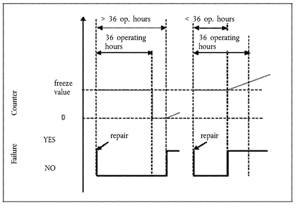
Once frozen, the counter shall be reset to zero when the monitors relevant to that counter have run at least once to completion of their monitoring cycle without having detected a malfunction and no malfunction relevant to that counter has been detected during 36 engine operating hours since the counter was last held (see Figure 1).
4.2.1.4.
The counter shall continue counting from the point at which it had been held if a malfunction relevant to that counter is detected during a period when the counter is frozen (see Figure 1).
Figure 1
Reactivation and resetting to zero of a counter after a period when its value has been frozen
5.ILLUSTRATION OF THE ACTIVATION AND DEACTIVATION AND COUNTER MECHANISMSU.K.
5.1.This Section illustrates the activation and deactivation and counter mechanisms for some typical cases. The figures and descriptions given in Sections 4.2, 4.3 and 4.4 are provided solely for the purposes of illustration in this Annex and should not be referenced as examples of either the requirements of this Regulation or as definitive statements of the processes involved. For simplification purposes, for example, the fact that the warning system will also be active when the inducement system is active has not been mentioned in the illustrations given.U.K.
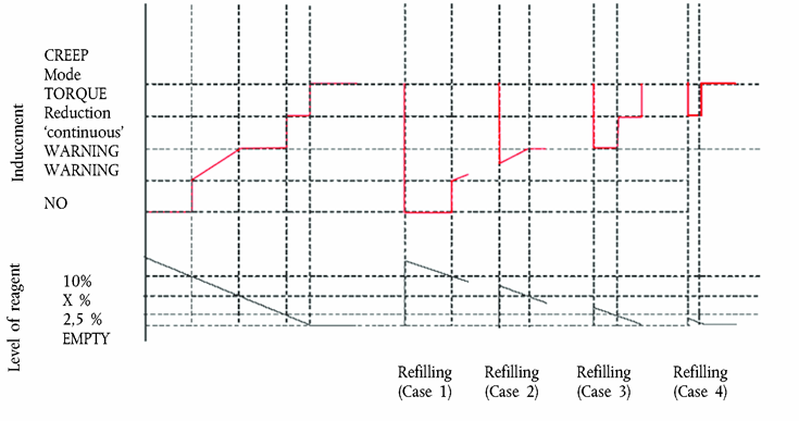
5.2.Figure 2 illustrates the operation of the activation and deactivation mechanisms when monitoring the reagent availability for five cases:U.K.
(a)
use case 1: the driver continues operating the vehicle in spite of the warning until vehicle operation is disabled;
(b)
repair case 1 (‘adequate’ refilling): the driver refills the reagent tank so that a level above the 10 % threshold is reached. Warning and inducement are de-activated;
(c)
repair cases 2 and 3 (‘inadequate’ refilling): The warning system is activated. The level of warning depends on the amount of available reagent;
(d)
repair case 4 (‘very inadequate’ refilling): The low-level inducement is activated immediately.
5.3.Figure 3 illustrates three cases of wrong urea quality:U.K.
(a)
use case 1: the driver continues operating the vehicle in spite of the warning until vehicle operation is disabled;
(b)
repair case 1 (‘bad’ or ‘dishonest’ repair): after disablement of the vehicle, the driver changes the quality of the reagent, but, soon after, changes it again for a poor quality one. The inducement system is immediately reactivated and vehicle operation is disabled after 2 engine operating hours;
(c)
repair case 2 (‘good’ repair): after disablement of the vehicle, the driver rectifies the quality of the reagent. However, some time afterwards, he refills again with a poor quality reagent. The warning, inducement, and counting processes restart from zero.

5.4.Figure 4 illustrates three cases of failure of the urea dosing system. This figure also illustrates the process that applies in the case of the monitoring failures described in Section 9.U.K.
(a)
Use case 1: the driver continues operating the vehicle in spite of the warning until vehicle operation is disabled.
(b)
Repair case 1 (‘good’ repair): after disablement of the vehicle, the driver repairs the dosing system. However, some time afterwards, the dosing system fails again. The warning, inducement, and counting processes restart from zero.
(c)
Repair case 2 (‘bad’ repair): during the low-level inducement time (torque reduction), the driver repairs the dosing system. Soon after, however, the dosing system fails again. The low-level inducement system is immediately reactivated and the counter restarts from the value it had at the time of repair.

Appendix 3
Low-level inducement torque reduction scheme U.K.
This diagram illustrates the provisions of Section 5.3 on torque reduction.

Appendix 4
Demonstration of correct installation on a vehicle in the case of engines EC type-approved as a separate technical unit U.K.
This Appendix applies when the vehicle manufacturer requests EC type-approval of a vehicle with an approved engine with regard to emissions and access to vehicle repair and maintenance information in accordance with this Regulation and Regulation (EC) No 595/2009.
In this case, and in addition to the installation requirements of Annex I, a demonstration of the correct installation is required. This demonstration shall be performed by the presentation to the approval authority of a technical case using evidence such as engineering drawings, functional analyses, and the results of previous tests.
Where appropriate, and if the manufacturer chooses, the evidence presented may include installations of systems or components on real or simulated vehicles, provided that the manufacturer can present evidence that the presented installation properly represents the standard that will be achieved in production.
The demonstration shall address the conformity of the following elements to the requirements of this Annex:
(a)
the installation on board the vehicle as regards its compatibility with the engine system (hardware, software and communication);
(b)
the warning and inducement systems (for example, pictograms, activation schemes, etc.);
(c)
the reagent tank and the elements (for example, sensors) mounted on the vehicle for the purpose of complying with this Annex.
Correct activation of the warning and inducement systems, and of the information storage and on-board and off-board communication systems, may be checked. No check of these systems shall require the dismounting of the engine system or components, nor shall it generate unnecessary testing burden by requiring processes such as changing of the urea quality or running of the vehicle or engine for long periods of time. In order to minimise the burden upon the vehicle manufacturer, electric disconnections and simulation of counters with high operating hours shall be selected as checks on these systems if possible.
Appendix 5
Access to ‘NOx control information’ U.K.
1.This Appendix describes the specifications permitting access to information required in order to check the status of the vehicle with regard to the correct operation of the NOx control system (NOx control information).U.K.
2.ACCESS METHODSU.K.
2.1.The ‘NOx control information’ shall be provided only in accordance with the standard or standards used in association with the retrieval of engine system information from the OBD system.U.K.
2.2.Access to the ‘NOx control information’ shall not be dependent on any access code or other device or method obtainable only from the manufacturer or the manufacturer’s suppliers. Interpretation of that information shall not require any specialised or unique decoding information, unless that information is publicly available.U.K.
2.3.It shall be possible to retrieve all ‘NOx control information’ from the system using the access method that is used to retrieve OBD information in accordance with Annex X.U.K.
2.4.It shall be possible to retrieve all ‘NOx control information’ information from the system using the test equipment that is used to retrieve OBD information in accordance with Annex X.U.K.
2.5.The ‘NOx control information’ shall be available through ‘read-only’ access (that is, it shall not be possible to clear, reset, erase, or modify any of the data).U.K.
3.INFORMATION CONTENTU.K.
3.1.The ‘NOx control information’ shall contain at least the following information:U.K.
(a)
the VIN (vehicle identification number);
(b)
the status of the warning system (active; non-active);
(c)
the status of the low-level inducement system (active; enabled; non-active);
(d)
the status of the severe inducement system (active; enabled; non-active);
(e)
[F1number of warm-up cycles and number of engine operating hours since recorded ‘NO x control information’ was cleared due to service or repair;]
(f)
the types of the counters relevant to this Annex (reagent quality, reagent consumption, dosing system, EGR valve, monitoring system) and the number of engine operating hours indicated by each of the these counters; in the case of multiple counters being used, the value to be considered for the purposes of the ‘NOx control information’ is the value of each of the counters relative to the failure under consideration having the highest value;
(g)
the DTCs associated with the malfunctions relevant to this Annex and their status (‘potential’, ‘confirmed and active’, etc.).
Appendix 6
Demonstration of the minimum acceptable reagent concentration CDmin U.K.
1.The manufacturer shall demonstrate the correct value of CDmin during type-approval by performing the hot part of the WHTC cycle, in accordance with the provisions of Annex 4B to UN/ECE Regulation No 49, using a reagent with the concentration CDmin.U.K.
2.The test shall follow the appropriate pre-conditioning cycle, permitting a closed loop NOx control system to perform adaptation to the quality of the reagent with the concentration CDmin.U.K.
3.The pollutant emissions resulting from this test shall be lower than the emission limits specified in Sections 7.1.1 and 7.1.1.1 of this Annex.U.K.
Options/Help
Print Options
PrintThe Whole Regulation
PrintThis Annex only
You have chosen to open the Whole Regulation
The Whole Regulation you have selected contains over 200 provisions and might take some time to download. You may also experience some issues with your browser, such as an alert box that a script is taking a long time to run.
Would you like to continue?
You have chosen to open Schedules only
The Schedules you have selected contains over 200 provisions and might take some time to download. You may also experience some issues with your browser, such as an alert box that a script is taking a long time to run.
Would you like to continue?
Legislation is available in different versions:
Latest Available (revised):The latest available updated version of the legislation incorporating changes made by subsequent legislation and applied by our editorial team. Changes we have not yet applied to the text, can be found in the ‘Changes to Legislation’ area.
Original (As adopted by EU): The original version of the legislation as it stood when it was first adopted in the EU. No changes have been applied to the text.
Point in Time: This becomes available after navigating to view revised legislation as it stood at a certain point in time via Advanced Features > Show Timeline of Changes or via a point in time advanced search.
See additional information alongside the content
Geographical Extent: Indicates the geographical area that this provision applies to. For further information see ‘Frequently Asked Questions’.
Show Timeline of Changes: See how this legislation has or could change over time. Turning this feature on will show extra navigation options to go to these specific points in time. Return to the latest available version by using the controls above in the What Version box.
Opening Options
Different options to open legislation in order to view more content on screen at once
More Resources
Access essential accompanying documents and information for this legislation item from this tab. Dependent on the legislation item being viewed this may include:
- the original print PDF of the as adopted version that was used for the EU Official Journal
- lists of changes made by and/or affecting this legislation item
- all formats of all associated documents
- correction slips
- links to related legislation and further information resources
Timeline of Changes
This timeline shows the different versions taken from EUR-Lex before exit day and during the implementation period as well as any subsequent versions created after the implementation period as a result of changes made by UK legislation.
The dates for the EU versions are taken from the document dates on EUR-Lex and may not always coincide with when the changes came into force for the document.
For any versions created after the implementation period as a result of changes made by UK legislation the date will coincide with the earliest date on which the change (e.g an insertion, a repeal or a substitution) that was applied came into force. For further information see our guide to revised legislation on Understanding Legislation.
More Resources
Use this menu to access essential accompanying documents and information for this legislation item. Dependent on the legislation item being viewed this may include:
- the original print PDF of the as adopted version that was used for the print copy
- correction slips
Click 'View More' or select 'More Resources' tab for additional information including:
- lists of changes made by and/or affecting this legislation item
- confers power and blanket amendment details
- all formats of all associated documents
- links to related legislation and further information resources
 All content is available under the Open Government Licence v3.0 except where otherwise stated. This site additionally contains content derived from EUR-Lex, reused under the terms of the Commission Decision 2011/833/EU on the reuse of documents from the EU institutions. For more information see the EUR-Lex public statement on re-use.