ANNEX IX
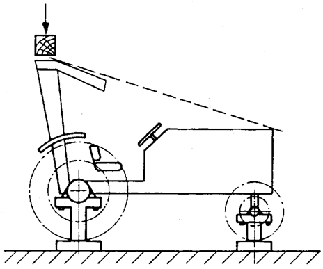
Requirements applying to roll-over protection structures (front mounted roll-over protective structures on narrow-track tractors) U.K.
A.GENERAL PROVISIONSU.K.
1.The Union requirements applying to roll-over protection structures (front mounted roll-over protective structures on narrow-track tractors) are set out in point B.U.K.
2.Tests may be performed in accordance with the static or alternatively the dynamic test procedures as set out in sections B1 and B2. The two methods are deemed equivalent.U.K.
3.In addition to the requirements set out in point 2, the requirements for foldable ROPS performance set out in section B3 shall be met.U.K.
4.In section B4 is set out the computer programme for determining the continuous or interrupted roll over behaviour which shall be used for the virtual testing.U.K.
B.REQUIREMENTS APPLYING TO ROLL-OVER PROTECTION STRUCTURES (FRONT MOUNTED ROLL-OVER PROTECTIVE STRUCTURES ON NARROW-TRACK TRACTORS)(1) U.K.
1. Definitions U.K.
1.1[Not applicable]U.K.
1.2. Roll-Over Protective Structure (ROPS) U.K.
Roll-over protective structure (protective cab or frame), hereinafter called ‘protective structure’, means the structure on a tractor the essential purpose of which is to avoid or limit risks to the driver resulting from roll-over of the tractor during normal use.
The roll-over protective structure is characterized by the provision of space for a clearance zone large enough to protect the driver when seated either inside the envelope of the structure or within a space bounded by a series of straight lines from the outer edges of the structure to any part of the tractor that might come into contact with flat ground and that is capable of supporting the tractor in that position if the tractor overturns.
1.3. Track U.K.
[1.3.1. Preliminary definition: median plane of the wheel or track U.K.
The median plane of the wheel or track is equidistant from the two planes containing the periphery of the rims or tracks at their outer edges.]
1.3.2.Definition of trackU.K.
The vertical plane through the wheel axis intersects its median plane along a straight line which meets the supporting surface at one point. If A and B are the two points thus defined for the wheels on the same axle of the tractor, then the track width is the distance between points A and B. The track may be thus defined for both front and rear wheels. Where there are twin wheels, the track is the distance between two planes each being the median plane of the pairs of wheels. [For tracklaying tractors, the track is the distance between the median planes of the tracks.]
1.3.3.Additional definition: median plane of the tractorU.K.
Take the extreme positions of points A and B for the tractor rear axle, which gives the maximum possible value for the track. The vertical plane at right angles to the line AB at its centre point is the median plane of the tractor.
1.4. Wheelbase U.K.
The distance between the vertical planes passing through the two lines AB as defined above, one for the front wheels and one for the rear-wheels. [For tractors fitted with tracks: the distance between the vertical planes perpendicular to the median longitudinal plane of the tractor passing through the axles of the driving wheels.]
1.5. Determination of seat index point; seat location and adjustment for test U.K.
1.5.1.Seat index point (SIP)(2) U.K.
The seat index point shall be determined in accordance with ISO 5353:1995
1.5.2.Seat location and adjustment for testU.K.
1.5.2.1.
where the seat position is adjustable, the seat must be adjusted to its rear uppermost position;
1.5.2.2.
where the inclination of the backrest is adjustable, it must be adjusted to the mid position;
1.5.2.3.
where the seat is equipped with suspension, the latter must be blocked at mid-travel, unless this is contrary to the instructions clearly laid down by the seat manufacturer;
1.5.2.4.
where the position of the seat is adjustable only lengthwise and vertically, the longitudinal axis passing through the Seat Index Point shall be parallel with the vertical longitudinal plane of the tractor passing through the centre of the steering wheel and not more than 100 mm from that plane.
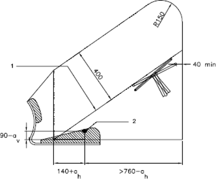
1.6. Clearance zone U.K.
1.6.1.Reference vertical plane and lineU.K.
The clearance zone (figure 6.1) is defined on the basis of a vertical reference plane and a reference line:
1.6.1.1.
The reference plane is a vertical plane, generally longitudinal to the tractor and passing through the Seat Index Point and the centre of the steering wheel. Normally the reference plane coincides with the longitudinal median plane of the tractor. This reference plane shall be assumed to move horizontally with the seat and steering wheel during loading but to remain perpendicular to the tractor or the floor of the roll-over protective structure.
1.6.1.2.
The reference line is the line contained in the reference plane that passes through a point located 140 + ah rearward and 90 – av below the Seat Index Point and the first point on the steering wheel rim that it intersects when brought to the horizontal.
1.6.2.Determination of the clearance zone for tractors with a non-reversible seatU.K.
The clearance zone for tractors with a non-reversible seat is defined in 1.6.2.1 to 1.6.2.11 below and is bounded by the following planes, the tractor being on a horizontal surface, the seat adjusted and located as specified in sections 1.5.2.1 to 1.5.2.4(3), and the steering wheel, where adjustable, adjusted to the mid position for seated driving:
1.6.2.1.
two vertical planes 250 mm on either side of the reference plane, these vertical planes extending 300 mm upwards from the plane defined in 1.6.2.8 below and longitudinally at least 550 mm in front of the vertical plane perpendicular to the reference plane passing (210 – ah ) mm in front of the Seat Index Point;
1.6.2.2.
two vertical planes 200 mm on either side of the reference plane, these vertical planes extending 300 mm upwards from the plane defined in 1.6.2.8 below and longitudinally from the surface defined in 1.6.2.11 below to the vertical plane perpendicular to the reference plane passing (210 – ah ) mm in front of the Seat Index Point;
1.6.2.3.
an inclined plane perpendicular to the reference plane, parallel with and 400 mm above the reference line, extending backwards to the point where it intersects the vertical plane which is perpendicular to the reference plane and which passes through a point (140 + ah ) mm rearward of the Seat Index Point;
1.6.2.4.
an inclined plane, perpendicular to the reference plane which meets the plane defined in 1.6.2.3 above at its rearmost edge and rests on the top of the seat back rest;
1.6.2.5.
a vertical plane perpendicular to the reference plane, passing at least 40 mm forward of the steering wheel and at least 760 – ah forward of the Seat Index Point;
1.6.2.6.
a cylindrical surface with its axis perpendicular to the reference plane, having a radius of 150 mm and tangential to the planes defined in 1.6.2.3 and 1.6.2.5;
1.6.2.7.
two parallel inclined planes passing through the upper edges of the planes defined in 1.6.2.1 above with the inclined plane on the side where the impact is applied no closer than 100 mm to the reference plane above the zone of clearance;
1.6.2.8.
a horizontal plane passing through a point 90 – av below the Seat Index Point;
1.6.2.9.
two portions of the vertical plane perpendicular to the reference plane passing 210 – ah forward of the Seat Index Point, both these part planes joining respectively the rearmost limits of the planes defined in 1.6.2.1 above to the foremost limits of the planes defined in 1.6.2.2 above;
1.6.2.10.
two portions of the horizontal plane passing 300 mm above plane defined in 1.6.2.8 above, both these part planes joining respectively the uppermost limits of the vertical planes defined in 1.6.2.2 above to the lowermost limits of the oblique planes defined in 1.6.2.7 above;
1.6.2.11.
a surface, curved if necessary, whose generating line is perpendicular to the reference plane and rests on the back of the seat backrest.
1.6.3.Determination of the clearance zone for tractors with a reversible driver’s positionU.K.
For tractors with a reversible driver’s position (reversible seat and steering wheel), the clearance zone is the envelope of the two clearance zones defined by the two different positions of the steering wheel and the seat. For each position of steering wheel and the seat the clearance zone shall respectively be defined on the basis of above sections 1.6.1 and 1.6.2 for driver’s position in normal position and on the basis of sections 1.6.1 and 1.6.2 of Annex X for driver’s position in reverse position (see figure 6.2).
1.6.4.Optional seatsU.K.
1.6.4.1.
In case of tractors that could be fitted with optional seats, the envelope comprising the Seat Index Points of all options offered shall be used during the tests. The protective structure shall not enter the larger clearance zone which takes account of these different Seat Index Points.
1.6.4.2.
In the case where a new seat option is offered after the test has been performed, a determination shall be made to see whether the clearance zone around the new SIP falls within the envelope previously established. If it does not, a new test must be performed.
1.6.4.3.
Optional seat does not include a seat for a person in addition to the driver and from where the tractor cannot be controlled. The SIP shall not be determined because the definition of the clearance zone is in relation to the driver seat.
1.7. Mass U.K.
1.7.1.Unballasted / Unladen MassU.K.
The mass of the tractor excluding optional accessories but including coolant, oils, fuel, tools plus the protective structure. Not included are optional front or rear weights, tyre ballast, mounted implements, mounted equipment or any specialised components;
1.7.2.Maximum Permissible MassU.K.
The maximum mass of the tractor stated by the manufacturer to be technically permissible and declared on the vehicle’s identification plate and/or in the Operator’s Handbook;
1.7.3.Reference MassU.K.
The mass, selected by the manufacturer, used in formulae to calculate the height of fall of the pendulum block, the energy inputs and crushing forces to be used in the tests. Must not be less than the unballasted mass and must be sufficient to ensure the Mass Ratio does not exceed 1,75 (see Sections 1.7.4 and 2.1.3);
1.7.4.Mass RatioU.K.
The ratio of  This must not be greater than 1,75.
1.8. Permissible measurement tolerances U.K.
| Linear dimension: | | ± 3 mm |
| except for: | - - tyre deflection: | ± 1 mm |
| - - structure deflection during horizontal loadings: | ± 1 mm |
| - - height of fall of the pendulum block: | ± 1 mm |
| Masses: | | ± 0,2 % (of the sensor full scale) |
| Forces: | | ± 0,1 % (of the full scale) |
| Angles: | | ± 0,1° |
1.9. Symbols U.K.
| ah | (mm) | Half of the horizontal seat adjustment |
| av | (mm) | Half of the vertical seat adjustment |
| B | (mm) | Minimum overall width of the tractor; |
| Bb | (mm) | Maximum outer width of the protective structure; |
| D | (mm) | Deflection of the structure at the point of impact (dynamic tests) or at the point of, and in line with, the load application (static tests); |
| D' | (mm) | Deflection of the structure for the calculated energy required; |
| Ea | (J) | Strain energy absorbed at point when load is removed. Area contained within F-D curve; |
| Ei | (J) | Strain energy absorbed. Area under F-D curve; |
| E'i | (J) | Strain energy absorbed after additional loading following a crack or tear; |
| E''i | (J) | Strain energy absorbed in overload test in the event of the load having been removed before starting this overload test. Area under F-D curve; |
| Eil | (J) | Energy input to be absorbed during longitudinal loading; |
| Eis | (J) | Energy input to be absorbed during side loading; |
| F | (N) | Static load force; |
| F' | (N) | Loading force for calculated energy required, corresponding to E’i ; |
| F-D | | Force/deflection diagram; |
| Fi | (N) | Force applied to rear hard fixture; |
| Fmax | (N) | Maximum static load force occurring during loading, with the exception of the overload; |
| Fv | (N) | Vertical crushing force; |
| H | (mm) | Falling height of the pendulum block (dynamic tests); |
| H’ | (mm) | Falling height of the pendulum block for additional test (dynamic tests); |
| I | (kg.m2) | Tractor reference moment of inertia about the centre line of the rear wheels, whatever the mass of these rear wheels may be; |
| L | (mm) | Tractor reference wheelbase; |
| M | (kg) | Tractor reference mass during strength tests. |
2. Field of application U.K.
2.1.This Annex shall apply to tractors having the following characteristics:U.K.
2.1.1.
ground clearance of not more than 600 mm beneath the lowest points of the front and rear axles, allowing for the differential;
2.1.2.
[fixed or adjustable minimum track width with one of the axles less than 1 150 mm fitted with tyres or tracks of a larger size. It is assumed that the axle mounted with the wider tyres or tracks is set at a track width of not more than 1 150 mm. It must be possible to set the track width of the other axle in such a way that the outer edges of the narrower tyres or tracks do not go beyond the outer edges of the tyres or tracks of the other axle. Where the two axles are fitted with rims and tyres or tracks of the same size, the fixed or adjustable track width of the two axles must be less than 1 150 mm;
2.1.3.
mass greater than 400 kg but less than 3 500 kg, corresponding to the unladen mass of the tractor, including the roll-over protective structure and tyres or tracks of the largest size recommended by the manufacturer. The maximum permissible mass shall not exceed 5 250 kg and the Mass Ratio (Maximum Permissible Mass/Reference Mass) must not be greater than 1,75;]
2.1.4.
and being fitted with roll-over protective structures of the dual-pillar type mounted only in front of the Seat Index Point and characterised by a reduced clearance zone attributable to the tractor silhouette, thus rendering it inadvisable, under any circumstances, to impede access to the driving position but worthwhile retaining these structures (fold-down or not) in view of their undoubted ease of use.
2.2.It is recognised that there may be designs of tractors, for example, special forestry machines, such as forwarders and skidders, for which this Annex is not applicable.U.K.
B1.STATIC TEST PROCEDUREU.K.
3. Rules and directions U.K.
3.1. Prior conditions for the strength tests U.K.
3.1.1.Completion of two preliminary testsU.K.
The protective structure may only be subjected to the strength tests if both the Lateral Stability Test and the Non-Continuous Rolling Test have been satisfactorily completed (see flow diagram as figure 6.3).
3.1.2.Preparation for the preliminary testsU.K.
3.1.2.1.The tractor must be equipped with the protective structure in its safety position.U.K.
3.1.2.2.The tractor must be fitted with tyres having the greatest diameter indicated by the manufacturer and the smallest cross-section for tyres of that diameter. The tyres must not be liquid-ballasted and must be inflated to the pressure recommended for field work.U.K.
3.1.2.3.The rear wheels must be set to the narrowest track width; the front wheels must be set as closely as possible to the same track width. If it is possible to have two front track settings which differ equally from the narrowest rear track setting, the wider of these two front track settings must be selected. [In case of tractor fitted with tracks, the manufacturer shall define the tracks setting.] U.K.
3.1.2.4.All the tractor’s tanks must be filled or the liquids must be replaced by an equivalent mass in the corresponding position.U.K.
3.1.2.5.All attachments used in the series production shall be fixed to the tractor in the normal position.U.K.
3.1.3.Lateral stability testU.K.
3.1.3.1.The tractor, prepared as specified above, is placed on a horizontal plane so that the tractor front-axle pivot point or, in the case of an articulated tractor, the horizontal pivot point between the two axles can move freely.U.K.
3.1.3.2.Using a jack or a hoist, tilt the part of the tractor which is rigidly connected to the axle that bears more than 50 per cent of the tractor’s weight, while constantly measuring the angle of inclination. [This angle must be at least 38° at the moment when the tractor is resting in a state of unstable equilibrium on the wheels or tracks touching the ground. Perform the test once with the steering wheel turned to full right lock and once with the steering wheel turned to full left lock.] U.K.
3.1.4.Non-continuous rolling testU.K.
3.1.4.1.General remarksU.K.
This test is intended to check whether a structure fitted to the tractor for the protection of the driver can satisfactorily prevent continuous roll-over of the tractor in the event of its overturning laterally on a slope with a gradient of 1 in 1.5 (figure 6.4).
Evidence of non-continuous rolling can be provided in accordance with one of the two methods described in 3.1.4.2 and 3.1.4.3.
3.1.4.2.Demonstration of non-continuous rolling behaviour by means of the overturning testU.K.
3.1.4.2.1.The overturning test must be carried out on a test slope at least four metres long (see figure 6.4). The surface must be covered with an 18-cm layer of a material that, as measured in accordance with Standards ASAE S313.3 FEB1999 and ASAE EP542 FEB1999 relating to soil cone penetrometer, has a cone penetration index of:U.K.
or
3.1.4.2.2.The tractor (prepared as described in paragraph 3.1.2) is tilted laterally with zero initial speed. For this purpose, it is placed at the start of the test slope in such a way that the wheels on the downhill side rest on the slope and the tractor’s median plane is parallel with the contour lines. After striking the surface of the test slope, the tractor may lift itself from the surface by pivoting about the upper corner of the protective structure, but it must not roll over. It must fall back on the side which it first struck.U.K.
3.1.4.3.Demonstration of non-continuous rolling behaviour by calculationU.K.
3.1.4.3.1.For the purpose of verifying non-continuous rolling behaviour by calculation, the following characteristic tractor data must be ascertained (see figure 6.5):U.K.
| [B 0 | (m) | Rear tyre or track width;] |
| B6 | (m) | Width of protective structure between the right and left points of impact; |
| B7 | (m) | Width of engine bonnet; |
| D0 | (rad) | Front-axle swing angle from zero position to end of travel; |
| [D 2 | (m) | Height of front tyres or tracks under full axle load; |
| D 3 | (m) | Height of rear tyres or tracks under full axle load;] |
| H0 | (m) | Height of the front-axle pivot point; |
| H1 | (m) | Height of centre of gravity; |
| H6 | (m) | Height at the point of impact; |
| H7 | (m) | Height of engine bonnet; |
| L2 | (m) | Horizontal distance between the centre of gravity and front axle; |
| L3 | (m) | Horizontal distance between the centre of gravity and rear axle; |
| L6 | (m) | Horizontal distance between the centre of gravity and the leading point of intersection of the protective structure (to be preceded by a minus sign if this point lies in front of the plane of the centre of gravity); |
| L7 | (m) | Horizontal distance between the centre of gravity and the front corner of the engine bonnet; |
| Mc | (kg) | Tractor mass used for calculation; |
| Q | (kgm2) | Moment of inertia about the longitudinal axis through the centre of gravity; |
| S | (m) | Rear track width.
[The sum of the rear track width (S) and tyre or track (B 0 ) widths must be greater than the width B 6 of the protective structure.]
|
3.1.4.3.2.For the purposes of calculation, the following simplifying assumptions can be made:U.K.
3.1.4.3.2.1.
the stationary tractor overturns on a slope with a 1/1,5 gradient with a balanced front axle, as soon as the centre of gravity is vertically above the axis of rotation;
3.1.4.3.2.2.
[the axis of rotation is parallel to the tractor's longitudinal axis and passes through the centre of the contact surfaces of the downhill front and rear wheel or track;]
3.1.4.3.2.3.
the tractor does not slide downhill;
3.1.4.3.2.4.
impact on the slope is partly elastic, with a coefficient of elasticity of:
3.1.4.3.2.5.
the depth of penetration into the slope and the deformation of the protective structure together amount to:
3.1.4.3.2.6.
no other components of the tractor penetrate into the slope.
[3.1.4.3.3. The computer programme (BASIC) for determining the continuous or interrupted roll-over behaviour of a laterally overturning narrow-track tractor with a front-mounted roll-over protective structure is described in section B4, with examples 6.1 to 6.11.] U.K.
3.1.5.Measurement methodsU.K.
3.1.5.1.Horizontal distances between the centre of gravity and rear (L3) or front (L2) axlesU.K.
The distance between the rear and front axles on both sides of the tractor shall be measured in order to verify there is no steering angle.
[The distances between the centre of gravity and the rear axle ( L 3 ) or the front axle ( L 2 ) shall be calculated from the mass distribution of the tractor between the rear and the front wheels or tracks.]
[3.1.5.2. Heights of rear ( D 3 ) and front ( D 2 ) tyres or tracks U.K.
The distance from the highest point of the tyre or tracks to the ground plane shall be measured (Figure 6.5), and the same method shall be used for the front and rear tyres or tracks.]
3.1.5.3.Horizontal distance between the centre of gravity and the leading point of intersection of the protective structure (L6).U.K.
The distance between the centre of gravity and the leading point of intersection of the protective structure shall be measured (figures 6.6.a, 6.6.b and 6.6.c). If the protective structure is in front of the plane of the centre of gravity, the recorded measure will be preceded by a minus sign (– L6).
3.1.5.4.Width of the protective structure (B6)U.K.
The distance between the right and left points of impact of the two vertical posts of the structure shall be measured.
[The point of impact is defined by the plane tangent to the protective structure passing through the line made by the top outer points of the front and rear tyres or tracks (Figure 6.7).]
3.1.5.5.Height of the protective structure (H6)U.K.
The vertical distance from the point of impact of the structure to the ground plane shall be measured.
3.1.5.6.Height of the engine bonnet (H7)U.K.
The vertical distance from the point of impact of the engine bonnet to the ground plane shall be measured.
[The point of impact is defined by the plane tangent to the engine bonnet and the protective structure passing through the top outer points of the front tyre or track (Figure 6.7). The measurement shall be made on both sides of the engine bonnet.]
3.1.5.7.Width of the engine bonnet (B7)U.K.
The distance between the two points of impact of the engine bonnet as defined previously shall be measured.
3.1.5.8.Horizontal distance between the centre of gravity and the front corner of the engine bonnet (L7)U.K.
The distance from the point of impact of the engine bonnet, as defined previously, to the centre of gravity shall be measured.
3.1.5.9.Height of the front-axle pivot point (H0)U.K.
[The vertical distance between the centre of the front-axle pivot point to the centre of axle of the front tyres or tracks ( H 01 ) shall be included in the manufacturer's technical report and shall be checked.
The vertical distance from the centre of the front tyres or tracks axle to the ground plane ( H 02 ) shall be measured (Figure 6.8).]
The height of the front-axle pivot (H0) is the sum of both previous values.
[3.1.5.10. Rear track width ( S ) U.K.
The minimum rear track width fitted with tyres or tracks of the largest size, as specified by the manufacturer, shall be measured (Figure 6.9).
3.1.5.11. Rear tyre or track width ( B 0 ) U.K.
The distance between the outer and the inner vertical planes of a rear tyre or track in its upper part shall be measured (Figure 6.9).]
3.1.5.12.Front axle swinging angle (D0)U.K.
The largest angle defined by the swinging of the front axle from the horizontal position to the maximum deflection shall be measured on both sides of the axle, taking into account any end-stroke shock absorber. The maximum angle measured shall be used.
3.1.5.13.Tractor MassU.K.
The tractor mass shall be determined according to the conditions specified in section 1.7.1.
3.2. Conditions for testing the strength of protective structures and of their attachment to tractors U.K.
3.2.1.General requirementsU.K.
3.2.1.1.Test purposesU.K.
Tests made using special rigs are intended to simulate such loads as are imposed on a protective structure, when the tractor overturns. These tests enable observations to be made on the strength of the protective structure and any brackets attaching it to the tractor and any parts of the tractor which transmit the test load.
3.2.1.2.Test methodsU.K.
Tests may be performed in accordance with the static procedure or the dynamic procedure (see Annex A). The two methods are deemed equivalent.
3.2.1.3.General rules governing preparation for testsU.K.
3.2.1.3.1.The protective structure must conform to the series production specifications. It shall be attached in accordance with the manufacturer’s recommended method to one of the tractors for which it is designed.U.K.
Note:A complete tractor is not required for the static strength test; however, the protective structure and parts of the tractor to which it is attached represent an operating installation, hereinafter referred to as ‘the assembly’.U.K.
3.2.1.3.2.For both the static test and the dynamic test the tractor as assembled (or the assembly) must be fitted with all series production components which may affect the strength of the protective structure or which may be necessary for the strength test.U.K.
Components which may create a hazard in the clearance zone must also be fitted on the tractor (or the assembly) so that they may be examined to see whether the requirements of the Acceptance Conditions in 3.2.3 have been fulfilled.
All components of the tractor or the protective structure including weather protective must be supplied or described on drawings.
3.2.1.3.3.For the strength tests, all panels and detachable non-structural components must be removed so that they may not contribute to the strengthening of the protective structure.U.K.
[3.2.1.3.4. The track width must be adjusted so that the protective structure will, as far as possible, not be supported by the tyres or tracks during the strength tests. If these tests are conducted in accordance with the static procedure, the wheels or tracks may be removed.] U.K.
3.2.2.TestsU.K.
3.2.2.1.Sequence of tests according to the Static ProcedureU.K.
The sequence of tests, without prejudice to the additional tests mentioned in sections 3.3.1.6, and 3.3.1.7 is as follows:
(1)
loading at the rear of the structure
(see 3.3.1.1);
(2)
rear crushing test
(see 3.3.1.4);
(3)
loading at the front of the structure
(see 3.3.1.2);
(4)
loading at the side of the structure
(see 3.3.1.3);
(5)
crushing at the front of the structure
(see 3.3.1.5).
3.2.2.2.General requirementsU.K.
3.2.2.2.1.If, during the test, any part of the tractor restraining equipment breaks or moves, the test shall be restarted.U.K.
3.2.2.2 2.No repairs or adjustments of the tractor or protective structure may be carried out during the tests.U.K.
3.2.2.2.3.The tractor gear box shall be in neutral and the brakes off during the tests.U.K.
[3.2.2.2.4. If the tractor is fitted with a suspension system between the tractor body and the wheels or tracks, it shall be blocked during the tests.] U.K.
3.2.2.2.5.The side chosen for application of the first load on the rear of the structure shall be that which, in the opinion of the testing authorities, will result in the application of the series of loads under the most unfavourable conditions for the structure. The lateral load and the rear load shall be applied on both sides of the longitudinal median plane of the protective structure. The front load shall be applied on the same side of the longitudinal median plane of the protective structure as the lateral load.U.K.
3.2.3.Acceptance conditionsU.K.
3.2.3.1.A protective structure is regarded as having satisfied the strength requirements if it fulfils the following conditions:U.K.
3.2.3.1.1.
After each part-test it must be free from cracks or tears within the meaning of section 3.3.2.1 or
3.2.3.1.2.
If, during one of the crushing tests, significant cracks or tears appear, an additional test, in accordance with section 3.3.1.7, must be applied immediately after the crushing which caused cracks or tears to appear;
3.2.3.1.3.
during the tests other than the overload test, no part of the protective structure must enter the clearance zone as defined in 1.6;
3.2.3.1.4.
during the tests other than the overload test, all parts of the clearance zone shall be secured by the structure, in accordance with 3.3.2.2;
3.2.3.1.5.
during the tests the protective structure must not impose any constraints on the seat structure;
3.2.3.1.6.
the elastic deflection, measured in accordance with 3.3.2.4 shall be less than 250 mm.
3.2.3.2.There shall be no accessories presenting a hazard for the driver. There shall be no projecting part or accessory which is liable to injure the driver should the tractor overturn, or any accessory or part which is liable to trap him — for example by the leg or the foot — as a result of the deflections of the structure.U.K.
3.2.4.[Not applicable]U.K.
3.2.5.Test apparatus and equipmentU.K.
3.2.5.1.Static testing rigU.K.
3.2.5.1.1.The static testing rig must be designed in such a way as to permit thrusts or loads to be applied to the protective structure.U.K.
3.2.5.1.2.Provision must be made so that the load can be uniformly distributed normal to the direction of loading and along a flange having a length of one of the exact multiples of 50 between 250 and 700 mm. The stiff beam shall have a vertical face dimension of 150 mm. The edges of the beam in contact with the protective structure shall be curved with a maximum radius of 50 mm.U.K.
3.2.5.1.3.The pad shall be capable of being adjusted to any angle in relation to the load direction, in order to be able to follow the angular variations of the structure’s load-bearing surface as the structure deflects.U.K.
3.2.5.1.4.Direction of the force (deviation from horizontal and vertical):U.K.
at start of test, under zero load: ± 2°;
during test, under load: 10° above and 20° below the horizontal. These variations must be kept to a minimum.
3.2.5.1.5.The deflection rate shall be sufficiently slow, less than 5 mm/s so that the load may at all moments be considered as static.U.K.
3.2.5.2.Apparatus for measuring the energy absorbed by the structureU.K.
3.2.5.2.1.The force versus deflection curve shall be plotted in order to determine the energy absorbed by the structure. There is no need to measure the force and deflection at the point where the load is applied to the structure; however, force and deflection shall be measured simultaneously and co-linearly.U.K.
3.2.5.2.2.The point of origin of deflection measurements shall be selected so as to take account only of the energy absorbed by the structure and/or by the deflection of certain parts of the tractor. The energy absorbed by the deflection and/or the slipping of the anchoring must be ignored.U.K.
3.2.5.3.Means of anchoring the tractor to the groundU.K.
3.2.5.3.1.Anchoring rails with the requisite track width and covering the necessary area for anchoring the tractor in all the cases illustrated must be rigidly attached to a non-yielding base near the testing rig.U.K.
3.2.5.3.2.The tractor must be anchored to the rails by any suitable means (plates, wedges, wire ropes, jacks, etc.) so that it cannot move during the tests. This requirement shall be checked during the test, by means of the usual devices for measuring length.U.K.
If the tractor moves, the entire test shall be repeated, unless the system for measuring the deflections taken into account for plotting the force versus deflection curve is connected to the tractor.
[3.2.5.4. Crushing rig U.K.
A rig as shown in Figure 6.10 shall be capable of exerting a downward force on a protective structure through a rigid beam approximately 250 mm wide, connected to the load-applying mechanism by means of universal joints. Suitable axle stands must be provided so that the tractor tyres or tracks do not bear the crushing force.]
3.2.5.5.Other measuring apparatusU.K.
The following measuring devices are also needed:
3.2.5.5.1.
A device for measuring the elastic deflection (the difference between the maximum momentary deflection and the permanent deflection, see figure 6.11).
3.2.5.5.2.
A device for checking that the protective structure has not entered the clearance zone and that the latter has remained within the structure’s protection during the test (section 3.3.2.2).
3.3. Static test procedure U.K.
3.3.1.Loading and crushing testsU.K.
3.3.1.1.Loading at the rearU.K.
3.3.1.1.1.The load shall be applied horizontally in a vertical plane parallel to the tractor’s median plane.U.K.
The load application point shall be that part of the roll-over protective structure likely to hit the ground first in a rearward overturning accident, normally the upper edge. The vertical plane in which the load is applied shall be located at a distance of 1/6 of the width of the top of the protective structure inwards from a vertical plane, parallel to the median plane of the tractor, touching the outside extremity of the top of the protective structure.
If the structure is curved or protruding at this point, wedges enabling the load to be applied thereon shall be added, without thereby reinforcing the structure.
3.3.1.1.2.The assembly shall be lashed to the ground as described in 3.2.6.3.U.K.
3.3.1.1.3.The energy absorbed by the protective structure during the test shall be at least:U.K.
3.3.1.1.4.For tractors with a reversible driver’s position (reversible seat and steering wheel), the same formula shall apply.U.K.
3.3.1.2.Loading at the frontU.K.
3.3.1.2.1.The load shall be applied horizontally, in a vertical plane parallel to the tractor’s median plane and located at a distance of 1/6 of the width of the top of the protective structure inwards from a vertical plane, parallel to the median plane of the tractor, touching the outside extremity of the top of the protective structure.U.K.
The load application point shall be that part of the roll-over protective structure likely to hit the ground first if the tractor overturned sideways while travelling forward, normally the upper edge.
If the structure is curved or protruding at this point, wedges enabling the load to be applied thereon shall be added, without thereby reinforcing the structure.
3.3.1.2.2.The assembly shall be lashed to the ground as described in 3.2.5.3.U.K.
3.3.1.2.3.The energy absorbed by the protective structure during the test shall be at least:U.K.
3.3.1.2.4.For tractors with a reversible driver’s position (reversible seat and steering wheel), the energy shall be whichever is the higher of the above or either of the following as selected:U.K.
or
3.3.1.3.Loading from the sideU.K.
3.3.1.3.1.The side loading shall be applied horizontally, in a vertical plane perpendicular to the tractor’s median plane. The load application point shall be that part of the roll-over protective structure likely to hit the ground first in a sideways overturning accident, normally the upper edge.U.K.
3.3.1.3.2.The assembly shall be lashed to the ground as described in 3.2.5.3.U.K.
3.3.1.3.3.The energy absorbed by the protective structure during the test shall be at least:U.K.
3.3.1.3.4.For tractors with a reversible driver’s position (reversible seat and steering wheel), the energy shall be whichever is higher of the above or the following:U.K.
3.3.1.4.Crushing at the rearU.K.
The beam shall be positioned over the rear uppermost structural member(s) and the resultant of crushing forces shall be located in the tractor’s median plane. A force Fv shall be applied where:
The force Fv shall be maintained for five seconds after cessation of any visually detectable movement of the protective structure.
Where the rear part of the protective structure roof will not sustain the full crushing force, the force shall be applied until the roof is deflected to coincide with the plane joining the upper part of the protective structure with that part of the rear of the tractor capable of supporting the tractor when overturned.
The force shall then be removed, and the crushing beam repositioned over that part of the protective structure which would support the tractor when completely overturned. The crushing force Fv shall then be applied again.
3.3.1.5.Crushing at the frontU.K.
The beam shall be positioned across the front uppermost structural member(s) and the resultant of crushing forces shall be located in the tractor’s median plane. A force Fv shall be applied where:
The force Fv shall be maintained for five seconds after the cessation of any visually detectable movement of the protective structure.
Where the front part of the protective structure roof will not sustain the full crushing force, the force shall be applied until the roof is deflected to coincide with the plane joining the upper part of the protective structure with that part of the front of the tractor capable of supporting the tractor when overturned.
The force shall then be removed, and the crushing beam repositioned over that part of the protective structure which would support the tractor when completely overturned. The crushing force Fv shall then be applied again.
3.3.1.6.Additional overload test (figures 6.14 to 6.16)U.K.
An overload test shall be carried out in all cases where the force decreases by more than 3 per cent during the last 5 per cent of the deflection reached when the energy required is absorbed by the structure (see figure 6.15).
The overload test involves the gradual increase of the horizontal load by increments of 5 per cent of the initial energy requirement up to a maximum of 20 per cent of energy added (see figure 6.16).
The overload test is satisfactory if, after each increase by 5, 10 or 15 per cent in the energy required, the force decreases by less than 3 per cent for a 5 per cent increment and remains greater than 0,8 Fmax.
The overload test is satisfactory if, after the structure has absorbed 20 per cent of the added energy, the force exceeds 0,8 Fmax.
Additional cracks or tears and/or entry into or lack of protection of the clearance zone due to elastic deflection are permitted during the overload test. However, after the removal of the load, the structure shall not enter the clearance zone, which shall be completely protected.
3.3.1.7.Additional crushing testsU.K.
If cracks or tears which cannot be considered as negligible appear during a crushing test, a second, similar crushing, but with a force of 1,2 Fv shall be applied immediately after the crushing test which caused the cracks or tears to appear.
3.3.2.Measurements to be madeU.K.
3.3.2.1.Fractures and cracksU.K.
After each test all structural members, joints and attachment systems shall be visually examined for fractures or cracks, any small cracks in unimportant parts being ignored.
3.3.2.2.Entry into the clearance zoneU.K.
During each test the protective structure shall be examined to see whether any part of it has entered the clearance zone as defined in 1.6 above.
Furthermore, the clearance zone shall not be outside the protection of the protective structure. For this purpose, it shall be considered to be outside the protection of the structure if any part of it would come in contact with flat ground if the tractor overturned towards the direction from which the test load is applied. [For estimating this, the front and rear tyres or tracks and track width setting shall be the smallest standard fitting specified by the manufacturer.]
3.3.2.3.Rear hard fixture testsU.K.
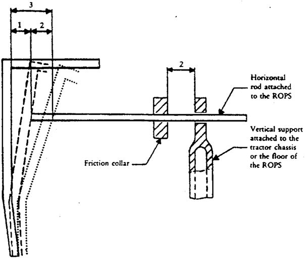
If the tractor is fitted with a rigid section, a housing or other hard fixture placed behind the driver’s seat, this fixture shall be regarded as a protective point, in the event of sideways or rear overturning. This hard fixture placed behind the driver’s seat shall be capable of withstanding, without breaking or entering the clearance zone, a downward force Fi, where:
applied perpendicularly to the top of the frame in the central plane of the tractor. The initial angle of application of force shall be 40° calculated from a parallel to the ground as shown in figure 6.12. The minimum width of this rigid section shall be 500 mm (see figure 6.13).
In addition, it shall be sufficiently rigid and firmly attached to the rear of the tractor.
3.3.2.4.Elastic deflection under side loadingU.K.
The elastic deflection shall be measured (810 + av ) mm above the Seat Index Point, in the vertical plane in which the load is applied. For this measurement, any apparatus similar to that illustrated in figure 6.11 shall be used.
3.3.2.5.Permanent deflectionU.K.
After the final crushing test the permanent deflection of the protective structure shall be recorded. For this purpose, before the start of the test, the position of the main roll-over protective structure members in relation to the Seat Index Point shall be recorded.
3.4. Extension to other tractor models U.K.
3.4.1.[Not applicable]U.K.
3.4.2.Technical extensionU.K.
When technical modifications occur on the tractor, the protective structure or the method of attachment of the protective structure to the tractor, the testing station that has carried out the original test can issue a ‘technical extension report’ if the tractor and protective structure satisfied preliminary tests of lateral stability and non-continuous rolling as defined in 3.1.3 and 3.1.4 and if the rear hard fixture as described in paragraph 3.3.2.3., when fitted, has been tested in accordance with the procedure described in this paragraph (except 3.4.2.2.4) in the following cases:
3.4.2.1.Extension of the structural test results to other models of tractorsU.K.
The impact or loading and crushing tests need not be carried out on each model of tractor, provided that the protective structure and tractor comply with the conditions referred to hereunder in 3.4.2.1.1 to 3.4.2.1.5.
3.4.2.1.1.
The structure (including rear hard fixture) shall be identical to the one tested;
3.4.2.1.2.
The required energy shall not exceed the energy calculated for the original test by more than 5 per cent;
3.4.2.1.3.
The method of attachment and the tractor components to which the attachment is made shall be identical;
3.4.2.1.4.
Any components such as mud-guards and bonnet that may provide support for the protective structure shall be identical;
3.4.2.1.5.
The position and critical dimensions of the seat in the protective structure and the relative position of the protective structure on the tractor shall be such that the clearance zone would have remained within the protection of the deflected structure throughout all tests (this shall be checked by using the same reference of clearance zone as in the original test report, respectively Seat Reference Point [SRP] or Seat Index Point [SIP]).
3.4.2.2.Extension of the structural test results to modified models of the protective structureU.K.
This procedure has to be followed when the provisions of section 3.4.2.1 are not fulfilled, it may not be used when the method of attachment of the protective structure to the tractor does not remain of the same principle (e.g. rubber supports replaced by a suspension device):
3.4.2.2.1.
Modifications having no impact on the results of the initial test (e.g. weld attachment of the mounting plate of an accessory in a non-critical location on the structure), addition of seats with different SIP location in the protective structure (subject to checking that the new clearance zone(s) remain(s) within the protection of the deflected structure throughout all tests).
3.4.2.2.2.
Modifications having a possible impact on the results of the original test without calling into question the acceptability of the protective structure (e.g. modification of a structural component, modification of the method of attachment of the protective structure to the tractor). A validation test can be carried out and the test results will be drafted in the extension report.
The following limits for this type extension are fixed:
3.4.2.2.2.1.
no more than 5 extension may be accepted without a validation test;
3.4.2.2.2.2.
the results of the validation test will be accepted for extension if all the acceptance conditions of this Annex are fulfilled and:
if the deflection measured after each impact test does not deviate from the deflection measured after each impact test in the original test report by more than ± 7 % (in the case of dynamic tests);
if the force measured when the required energy level has been reached in the various horizontal load tests does not deviate from the force measured when the required energy has been reached in the original test by more than ± 7 % and the deflection measured(4) when the required energy level has been reached in the various horizontal load tests does not deviate from the deflection measured when the required energy has been reached in the original test report by more than ± 7 % (in the case of static tests).
3.4.2.2.2.3.
more than one protective structure modification may be included in a single extension report if they represent different options of the same protective structure, but only one validation test can be accepted in a single extension report. The options not tested shall be described in a specific section of the extension report.
3.4.2.2.3.
Increase of the reference mass declared by the manufacturer for a protective structure already tested. If the manufacturer wants to keep the same approval number it is possible to issue an extension report after having carried out a validation test (the limits of ± 7 % specified in 3.4.2.2.2.2 are not applicable in such a case).
3.4.2.2.4.
Modification of the rear hard fixture or addition of a new rear hard fixture. It has to be checked that the clearance zone remains within the protection of the deflected structure throughout all test taking into account the new or modified rear hard fixture. A validation of the rear hard fixture consisting in the test described in 3.3.2.3 has to be carried out and the test results will be drafted in the extension report.
3.5.[Not applicable]U.K.
3.6. Cold weather performance of protective structures U.K.
3.6.1.If the protective structure is claimed to have properties resistant to cold weather embrittlement, the manufacturer shall give details that shall be included in the report.U.K.
3.6.2.The following requirements and procedures are intended to provide strength and resistance to brittle fracture at reduced temperatures. It is suggested that the following minimum material requirements shall be met in judging the protective structure’s suitability at reduced operating temperatures in those countries requiring this additional operating protection.U.K.
3.6.2.1.Bolts and nuts used to attach the protective structure to the tractor and used to connect structural parts of the protective structure shall exhibit suitable controlled reduced temperature toughness properties.U.K.
3.6.2.2.All welding electrodes used in the fabrication of structural members and mounts shall be compatible with the protective structure material as given in 3.6.2.3 below.U.K.
3.6.2.3.Steel materials for structural members of the protective structure shall be of controlled toughness material exhibiting minimum Charpy V-Notch impact energy requirements as shown in Table 6.1. Steel grade and quality shall be specified in accordance with ISO 630:1995.U.K.
Steel with an as-rolled thickness less than 2,5 mm and with a carbon content less than 0,2 per cent is considered to meet this requirement.
Structural members of the protective structure made from materials other than steel shall have equivalent low temperature impact resistance.
3.6.2.4.When testing the Charpy V-Notch impact energy requirements, the specimen size shall be no less than the largest of the sizes stated in Table 6.1 that the material will permit.U.K.
3.6.2.5.The Charpy V-Notch tests shall be made in accordance with the procedure in ASTM A 370-1979, except for specimen sizes that shall be in accordance with the dimensions given in Table 6.1.U.K.
3.6.2.6.Alternatives to this procedure are the use of killed or semi-killed steel for which an adequate specification shall be provided. Steel grade and quality shall be specified in accordance with ISO 630:1995, Amd 1:2003.U.K.
3.6.2.7.Specimens are to be longitudinal and taken from flat stock, tubular or structural sections before forming or welding for use in the protective structure. Specimens from tubular or structural sections are to be taken from the middle of the side of greatest dimension and shall not include welds.U.K.
Table 6.1. Minimum Charpy V-notch impact energies U.K.
| |
| |
| Specimen size | Energy at | Energy at |
|---|
| – 30 °C | – 20 °C |
|---|
| mm | J | J |
|---|
| 10 × 10 | 11 | 27,5 |
| 10 × 9 | 10 | 25 |
| 10 × 8 | 9,5 | 24 |
| 10 × 7,5 | 9,5 | 24 |
| 10 × 7 | 9 | 22,5 |
| 10 × 6,7 | 8,5 | 21 |
| 10 × 6 | 8 | 20 |
| 10 × 5 | 7,5 | 19 |
| 10 × 4 | 7 | 17,5 |
| 10 × 3,5 | 6 | 15 |
| 10 × 3 | 6 | 15 |
| 10 × 2,5 | 5,5 | 14 |
3.7.[Not applicable]U.K.
Figure 6.1 U.K. Clearance zone U.K.Dimensions in mmU.K.
Figure 6.1.a Side view Cross-section through the reference plane
 | Figure 6.1.b Rear view 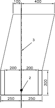 |
Figure 6.1.c View from above  |
Figure 6.2
Clearance zone for tractors with reversible seat and steering wheel
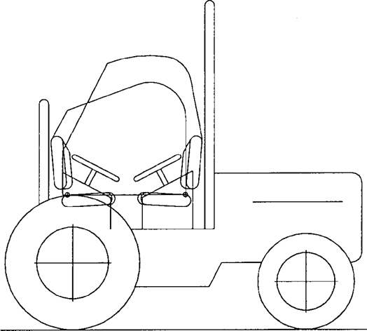
Figure 6.3
Flow diagram for determining the continuous roll-over behaviour of a laterally overturning tractor with a front mounted roll-over protective structure (ROPS)
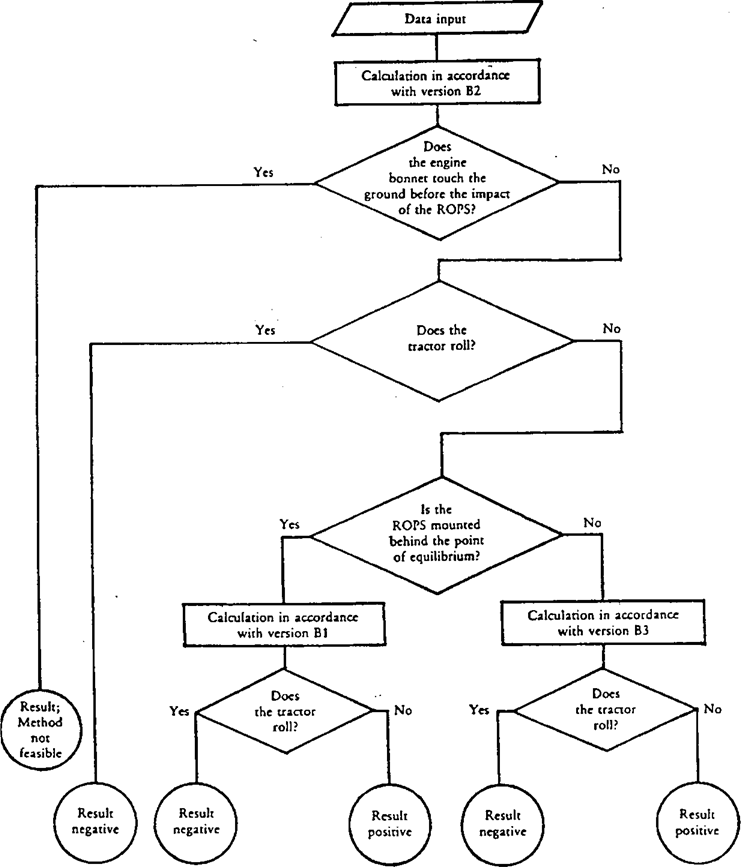
Version B1
:
Point of impact of ROPS behind longitudinally unstable equilibrium point
Version B2
:
Point of impact of ROPS near longitudinally unstable equilibrium point
Version B3
:
Point of impact of ROPS in front of longitudinally unstable equilibrium point
Figure 6.4
Rig for testing anti-roll properties on 1/1,5 gradient
[Figure 6.5 Data required for calculating the overturn of a tractor with triaxial rolling behaviour U.K.

Note: D2 and D3 should be measured under full axle load.] U.K.
Figures 6.6.a, 6.6.b, 6.6.c Horizontal distance between the centre of gravity and the leading point of intersection of the protective structure (L6) U.K.
Figure 6.7
Determination of points of impact for measurement of width of protective structure (B6) and height of engine bonnet (H7)
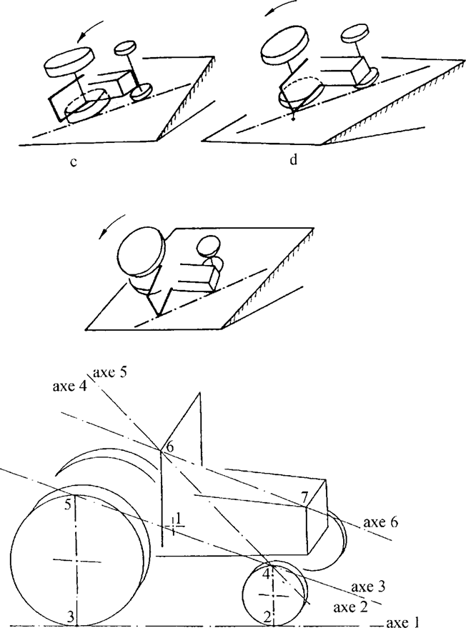
Figure 6.8
Height of the front-axle pivot point (H0)
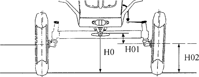
Figure 6.9
Rear track width (S) and Rear tyre width (B0)
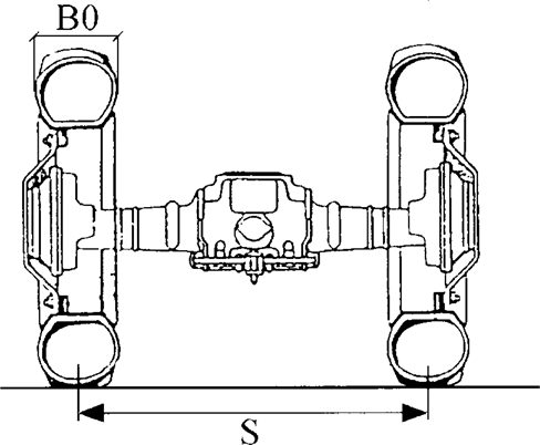
Figure 6.10
Example of crushing rig of the tractor

Figure 6.11
Example of apparatus for measuring elastic deflection
3
–
Total deflection (permanent plus elastic)
Figure 6.12
Simulated ground line
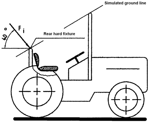
Figure 6.13
Minimum width of the rear hard fixture
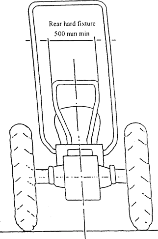
Figure 6.14
Force / deflection curve
Overload test not necessary
Notes:U.K.
1.Locate Fa in relation to 0,95 D’U.K.
2.Overload test not necessary as Fa ≤ 1,03 F’U.K.
Figure 6.15
Force / deflection curve
Overload test necessary
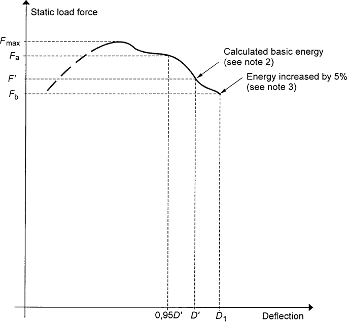
Notes:U.K.
1.Locate Fa in relation to 0,95 D’U.K.
2.Overload test necessary as Fa > 1,03 F’U.K.
3.Overload test performance satisfactory as Fb > 0,97 F’ and Fb > 0,8 Fmax.U.K.
Figure 6.16
Force / deflection curve
Overload test to be continued

Notes:U.K.
1.Locate Fa in relation to 0,95 D’U.K.
2.Overload test necessary as Fa > 1,03 F’U.K.
3.Fb < 0,97 F’ therefore further overload necessaryU.K.
4.Fc < 0,97 Fb therefore further overload necessaryU.K.
5.Fd < 0,97 Fc therefore further overload necessaryU.K.
6.Overload test performance satisfactory, if Fe > 0,8 Fmax U.K.
7.Failure at any stage when load drops below 0,8 Fmax.U.K.
B2.ALTERNATIVE ‘DYNAMIC’ TEST PROCEDUREU.K.
This section sets out the Dynamic Testing Procedure alternative to the static test procedure set out in section B1.
4. Rules and directions U.K.
4.1. Prior conditions for the strength tests U.K.
See requirements stated for static testing.
4.2. Conditions for testing the strength of protective structures and of their attachment to tractors U.K.
4.2.1.General requirementsU.K.
See requirements stated for static testing.
4.2.2.TestsU.K.
4.2.2.1.Sequence of tests according to the Dynamic ProcedureU.K.
The sequence of tests, without prejudice to the additional tests mentioned in sections 4.3.1.6 and 4.3.1.7 is as follows:
(1)
impact at the rear of the structure
(see 4.3.1.1);
(2)
rear crushing test
(see 4.3.1.4);
(3)
impact at the front of the structure
(see 4.3.1.2);
(4)
impact at the side of the structure
(see 4.3.1.3);
(5)
crushing at the front of the structure
(see 4.3.1.5).
4.2.2.2.General requirementsU.K.
4.2.2.2.1.If, during the test, any part of the tractor restraining equipment breaks or moves, the test shall be restarted.U.K.
4.2.2.2.2.No repairs or adjustments of the tractor or protective structure may be carried out during the tests.U.K.
4.2.2.2.3.The tractor gear box shall be in neutral and the brakes off during the tests.U.K.
4.2.2.2.4.If the tractor is fitted with a suspension system between the tractor body and the wheels, it shall be blocked during the tests.U.K.
4.2.2.2.5.The side chosen for application of the first impact on the rear of the structure shall be that which, in the opinion of the testing authorities, will result in the application of the series of impacts or loads under the most unfavourable conditions for the structure. The lateral impact and the rear impact shall be applied on both sides of the longitudinal median plane of the protective structure. The front impact shall be applied on the same side of the longitudinal median plane of the protective structure as the lateral impact.U.K.
4.2.3.Acceptance conditionsU.K.
4.2.3.1.A protective structure is regarded as having satisfied the strength requirements if it fulfils the following conditions:U.K.
4.2.3.1.1.
After each part-test it must be free from cracks or tears within the meaning of section 4.3.2.1 or
4.2.3.1.2.
If, during one of the tests, significant cracks or tears appear, an additional test, as defined in sections 4.3.1.6 or 4.3.1.7, must be applied immediately after the impact or the crushing test which caused cracks or tears to appear;
4.2.3.1.3.
during the tests other than the overload test, no part of the protective structure must enter the clearance zone as defined in 1.6;
4.2.3.1.4.
during the tests other than the overload test, all parts of the clearance zone shall be secured by the structure, in accordance with 4.3.2.2;
4.2.3.1.5.
during the tests the protective structure must not impose any constraints on the seat structure;
4.2.3.1.6.
the elastic deflection, measured in accordance with 4.3.2.4 shall be less than 250 mm.
4.2.3.2.There shall be no accessories presenting a hazard for the driver. There shall be no projecting part or accessory which is liable to injure the driver should the tractor overturn, or any accessory or part which is liable to trap him — for example by the leg or the foot — as a result of the deflections of the structure.U.K.
4.2.4.[Not applicable]U.K.
4.2.5.Apparatus and equipment for dynamic testsU.K.
4.2.5.1.Pendulum blockU.K.
4.2.5.1.1.A block acting as a pendulum must be suspended by two chains or wire ropes from pivot points not less than 6 m above the ground. Means must be provided for adjusting independently the suspended height of the block and the angle between the block and the supporting chains or wire ropesU.K.
4.2.5.1.2.The mass of the pendulum block must be 2 000 ± 20 kg excluding the mass of the chains or wire ropes which themselves must not exceed 100 kg. The length of the sides of the impact face must be 680 ± 20 mm (see figure 6.26). The block must be filled in such a way that the position of its centre of gravity is constant and coincides with the geometrical centre of the parallelepiped.U.K.
4.2.5.1.3.The parallelepiped must be connected to the system which pulls it backwards by an instantaneous release mechanism which is so designed and located as to enable the pendulum block to be released without causing the parallelepiped to oscillate about its horizontal axis perpendicular to the pendulum’s plane of oscillation.U.K.
4.2.5.2.Pendulum supportsU.K.
The pendulum pivot points must be rigidly fixed so that their displacement in any direction does not exceed 1 per cent of the height of fall.
4.2.5.3.LashingsU.K.
4.2.5.3.1.Anchoring rails with the requisite track width and covering the necessary area for lashing the tractor in all the cases illustrated (see figures 6.23, 6.24 and 6.25) must be rigidly attached to a non-yielding base beneath the pendulum.U.K.
4.2.5.3.2.The tractor shall be lashed to the rails by means of wire rope with round strand, fibre core, construction 6 × 19 in accordance with ISO 2408:2004 and a nominal diameter of 13 mm. The metal strands must have an ultimate tensile strength of 1 770 MPa.U.K.
4.2.5.3.3.The central pivot of an articulated tractor shall be supported and lashed down as appropriate for all tests. For the lateral impact test, the pivot shall also be propped from the side opposite the impact. The front and rear wheels need not be in line if this facilitates the attachment of the wire ropes in the appropriate manner.U.K.
4.2.5.4.Wheel prop and beamU.K.
4.2.5.4.1.A softwood beam of 150 mm square shall be used as a prop for the wheels during the impact tests (see figures 6.27, 6.28 and 6.29).U.K.
4.2.5.4.2.During the lateral impact tests, a softwood beam shall be clamped to the floor to brace the rim of the wheel opposite the side of impact (see figure 6.29).U.K.
4.2.5.5.Props and lashings for articulated tractorsU.K.
4.2.5.5.1.Additional props and lashings must be used for articulated tractors. Their purpose is to ensure that the section of the tractor on which the protective structure is fitted is as rigid as that of a non-articulated tractor.U.K.
4.2.5.5.2.Additional specific details are given in the section 4.3.1 for the impact and crushing tests.U.K.
4.2.5.6.Tyre pressures and deflectionsU.K.
4.2.5.6.1.The tractor tyres shall not be liquid-ballasted and shall be inflated to the pressures prescribed by the tractor manufacturer for field work.U.K.
4.2.5.6.2.The lashings shall be tensioned in each particular case such that the tyres undergo a deflection equal to 12 per cent of the tyre wall height (distance between the ground and the lowest point of the rim) before tensioning.U.K.
4.2.5.7.Crushing rigU.K.
A rig as shown in figure 6.10 shall be capable of exerting a downward force on a protective structure through a rigid beam approximately 250 mm wide connected to the load-applying mechanism by means of universal joints. Suitable axle stands shall be provided so that the tractor tyres do not bear the crushing force.
4.2.5.8.Measuring apparatusU.K.
The following measuring apparatus is needed:
4.2.5.8.1.
device for measuring the elastic deflection (the difference between the maximum momentary deflection and the permanent deflection, (see figure 6.11).
4.2.5.8.2.
device for checking that the protective structure has not entered the clearance zone and that the latter has remained within the structure’s protective during the test (see section 4.3.2.2).
4.3. Dynamic test procedure U.K.
4.3.1.Impact and crushing testsU.K.
4.3.1.1.Impact at the rearU.K.
4.3.1.1.1.The tractor shall be so placed in relation to the pendulum block that the block will strike the protective structure when the impact face of the block and the supporting chains or wire ropes are at an angle with the vertical plane A equal to M/100 with a 20° maximum, unless, during deflection, the protective structure at the point of contact forms a greater angle to the vertical. In this case the impact face of the block shall be adjusted by means of an additional support so that it is parallel to the protective structure at the point of impact at the moment of maximum deflection, the supporting chains or wire ropes remaining at the angle defined above.U.K.
The suspended height of the block shall be adjusted and necessary steps taken so as to prevent the block from turning about the point of impact.
The point of impact is that part of the protective structure likely to hit the ground first in a rearward overturning accident, normally the upper edge. The position of the centre of gravity of the block is 1/6 of the width of the top of the protective structure inwards from a vertical plan parallel to the median plane of the tractor touching the outside extremity of the top of the protective structure.
If the structure is curved or protruding at this point, wedges enabling the impact to be applied thereon must be added, without thereby reinforcing the structure.
4.3.1.1.2.The tractor must be lashed to the ground by means of four wire ropes, one at each end of both axles, arranged as indicated in figure 6.27. The spacing between the front and rear lashing points must be such that the wire ropes make an angle of less than 30° with the ground. The rear lashings must in addition be so arranged that the point of convergence of the two wire ropes is located in the vertical plane in which the centre of gravity of the pendulum block travels.U.K.
The wire ropes must be tensioned so that the tyres undergo the deflections given in 4.2.5.6.2. With the wire ropes tensioned, the wedging beam shall be placed in front of and tight against the rear wheels and then fixed to the ground.
4.3.1.1.3.If the tractor is of the articulated type, the point of articulation shall, in addition, be supported by a wooden block at least 100 mm square and firmly lashed to the ground.U.K.
4.3.1.1.4.The pendulum block shall be pulled back so that the height of its centre of gravity above that at the point of impact is given by one of the following two formulae, to be chosen according to the reference mass of the assembly subjected to the tests:U.K.
for tractor with a reference mass of less than 2 000 kg;
for tractor with a reference mass of more than 2 000 kg.
The pendulum block is then released and strikes the protective structure.
4.3.1.1.5.For tractors with a reversible driver’s position (reversible seat and steering wheel), the same formulae shall apply.U.K.
4.3.1.2.Impact at the frontU.K.
4.3.1.2.1.The tractor shall be so placed in relation to the pendulum block that the block will strike the protective structure when the impact face of the block and the supporting chains or wire ropes are at an angle with the vertical plane A equal to M/100 with a 20° maximum, unless, during deflection, the protective structure at the point of contact forms a greater angle to the vertical. In this case the impact face of the block shall be adjusted by means of an additional support so that it is parallel to the protective structure at the point of impact at the moment of maximum deflection, the supporting chains or wire ropes remaining at the angle defined above.U.K.
The suspended height of the pendulum block shall be adjusted and the necessary steps taken so as to prevent the block from turning about the point of impact.
The point of impact is that part of the protective structure likely to hit the ground first if the tractor overturned sideways while travelling forward, normally the upper edge. The position of the centre of gravity of the block is 1/6 of the width of the top of the protective structure inwards from a vertical plane parallel to the median plane of the tractor touching the outside extremity of the top of the protective structure.
If the structure is curved or protruding at this point, wedges enabling the impact to be applied thereon must be added, without thereby reinforcing the structure.
4.3.1.2.2.The tractor must be lashed to the ground by means of four wire ropes, one at each end of both axles, arranged as indicated in figure 6.28. The spacing between the front and rear lashing points must be such that the wire ropes make an angle of less than 30° with the ground. The rear lashings shall in addition be so arranged that the point of convergence of the two wire ropes is located in the vertical plane in which the centre of gravity of the pendulum block travels.U.K.
The wire ropes must be tensioned so that the tyres undergo the deflections given in 4.2.5.6.2. With the wire ropes tensioned, the wedging beam shall be placed behind and tight against the rear wheels and then fixed to the ground.
4.3.1.2.3.If the tractor is of the articulated type, the point of articulation shall, in addition, be supported by a wooden block at least 100 mm square and firmly lashed to the ground.U.K.
4.3.1.2.4.The pendulum block shall be pulled back so that the height of its centre of gravity above that at the point of impact is given by one of the following two formulae, to be chosen according to the reference mass of the assembly subjected to the tests:U.K.
for tractor with a reference mass of less than 2 000 kg.
for tractor with a reference mass of more than 2 000 kg.
The pendulum block is then released and strikes the protective structure.
4.3.1.2.5.For tractors with a reversible driver’s position (reversible seat and steering wheel), the height shall be whichever is greater from the formula applied above and that selected below:U.K.
or
4.3.1.3.Impact from the sideU.K.
4.3.1.3.1.The tractor shall be so placed in relation to the pendulum block that the block will strike the protective structure when the impact face of the block and the supporting chains or wire ropes are vertical unless, during deflection, the protective structure at the point of contact forms an angle of less than 20° to the vertical. In this case the impact face of the block shall be adjusted by means of an additional support so that it is parallel to the protective structure at the point of impact at the moment of maximum deflection, the supporting chains or wire ropes remaining vertical on impact.U.K.
The suspended height of the pendulum block shall be adjusted and necessary steps taken so as to prevent the block from turning about the point of impact.
The point of impact shall be that part of the protective structure likely to hit the ground first in a sideways overturning accident.
4.3.1.3.2.The tractor wheels on the side which is to receive the impact must be lashed to the ground by means of wire ropes passing over the corresponding ends of the front and rear axles. The wire ropes must be tensioned to produce the tyre deflection values given in 4.2.5.6.2.U.K.
With the wire ropes tensioned, the wedging beam shall be placed on the ground, pushed tight against the tyres on the side opposite that which is to receive the impact and then fixed to the ground. It may be necessary to use two beams or wedges if the outer sides of the front and rear tyres are not in the same vertical plane. The prop shall then be placed as indicated in figure 6.29 against the rim of the most heavily loaded wheel opposite to the point of impact, pushed firmly against the rim and then fixed at its base. The length of the prop shall be such that it makes an angle of 30° ± 3° with the ground when in position against the rim. In addition, its thickness shall, if possible, be between 20 and 25 times less than its length and between 2 and 3 times less than its width. The props shall be shaped at both ends as shown in the details on figure 6.29.
4.3.1.3.3.If the tractor is of the articulated type, the point of articulation shall in addition be supported by a wooden block at least 100 mm square and laterally supported by a device similar to the prop pushed against the rear wheel as in 4.3.1.3.2. The point of articulation shall then be lashed firmly to the ground.U.K.
4.3.1.3.4.The pendulum block shall be pulled back so that the height of its centre of gravity above that at the point of impact is given by one of the following two formulae, to be chosen according to the reference mass of the assembly subjected to the tests:U.K.
for tractor with a reference mass of less than 2 000 kg.
for tractor with a reference mass of more than 2 000 kg.
4.3.1.3.5.For reversible tractors, the height shall be whichever is greater of the results obtained from the formulae applicable above and below:U.K.
for tractor with a reference mass of less than 2 000 kg.
for tractor with a reference mass of more than 2 000 kg.
The pendulum block is then released and strikes the protective structure.
4.3.1.4.Crushing at the rearU.K.
All provisions are identical to those given in section 3.3.1.4 of Part B1.
4.3.1.5.Crushing at the frontU.K.
All provisions are identical to those given in section 3.3.1.5 of Part B1.
4.3.1.6.Additional impact testsU.K.
If cracks or tears which cannot be considered negligible appear during an impact test, a second, similar test, but with a height of fall of:
shall be performed immediately after the impact tests causing these tears or cracks to appear, ‘a’ being the ratio of the permanent deformation (Dp) to the elastic deformation (De):
as measured at the point of impact. The additional permanent deformation due to the second impact shall not exceed 30 per cent of the permanent deformation due to the first impact.
In order to be able to carry out the additional test, it is necessary to measure the elastic deformation during all the impact tests.
4.3.1.7.Additional crushing testsU.K.
If during a crushing test, significant cracks or tears appear, a second, similar, crushing test, but with a force equal to 1,2 Fv shall be performed immediately after the crushing tests which caused these tears or cracks to appear.
4.3.2.Measurements to be madeU.K.
4.3.2.1.Fractures and cracksU.K.
After each test all structural members, joints and fastening systems shall be visually examined for fractures or cracks, any small cracks in unimportant parts being ignored.
Any tears caused by the edges of the pendulum weight are to be ignored.
4.3.2.2.Entry into the clearance zoneU.K.
During each test the protective structure shall be examined to see whether any part of it has entered the clearance zone round the driving seat as defined in 1.6.
Furthermore, the clearance zone shall not be outside the protection of the protective structure. For this purpose, it shall be considered to be outside the protection of the structure if any part of it would come in contact with flat ground if the tractor overturned towards the direction from which the test load is applied. For estimating this, the front and rear tyres and track width setting shall be the smallest standard fitting specified by the manufacturer.
4.3.2.3.Rear hard fixture testsU.K.
If the tractor is fitted with a rigid section, a housing or other hard fixture placed behind the driver’s seat, this fixture shall be regarded as a protective point, in the event of sideways or rear overturning. This hard fixture placed behind the driver’s seat shall be capable of withstanding, without breaking or entering the clearance zone, a downward force Fi where:
applied perpendicularly to the top of the frame in the central plane of the tractor. The initial angle of application of force shall be 40° calculated from a parallel to the ground as shown in figure 6.12. The minimum width of this rigid section shall be 500 mm (see figure 6.13).
In addition, it shall be sufficiently rigid and firmly attached to the rear of the tractor.
4.3.2.4.Elastic deflection (under side impact)U.K.
The elastic deflection is measured (810 + av ) mm above the index point, in the vertical plane passing through the point of impact. For this measurement, apparatus similar to that illustrated in figure 6.11 shall be used.
4.3.2.5.Permanent deflectionU.K.
After the final crushing test, the permanent deflection of the protective structure shall be recorded. For this purpose, before the start of the test, the position of the main roll-over protective structure members in relation to the Seat Index Point shall be used.
4.4. Extension to other tractor models U.K.
All provisions are identical to those given in section 3.4 of section B1 to this Annex.
4.5.[Not applicable]U.K.
4.6. Cold weather performance of protective structures U.K.
All provisions are identical to those given in section 3.6 of section B1 to this Annex.
4.7.[Not applicable]U.K.
Figure 6.26
Pendulum block and its suspending chains or wire ropes
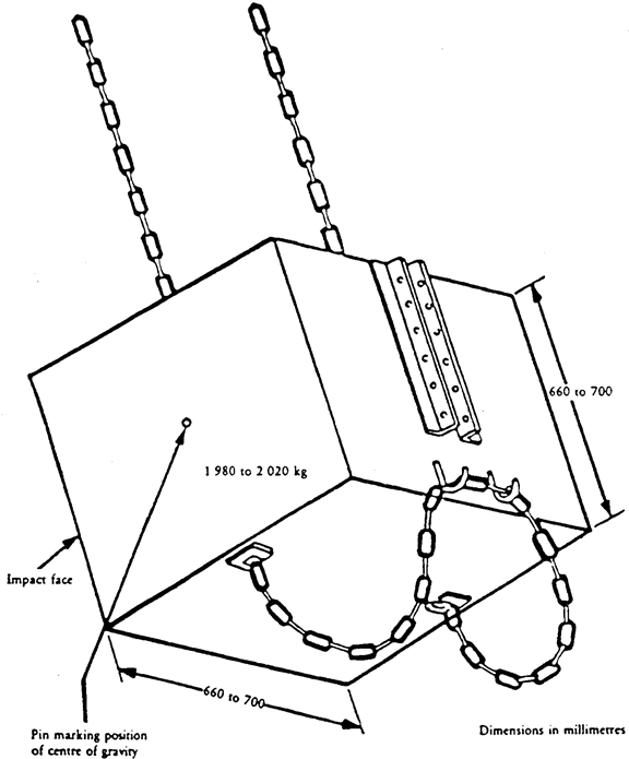
Figure 6.27
Example of tractor lashing (rear impact)
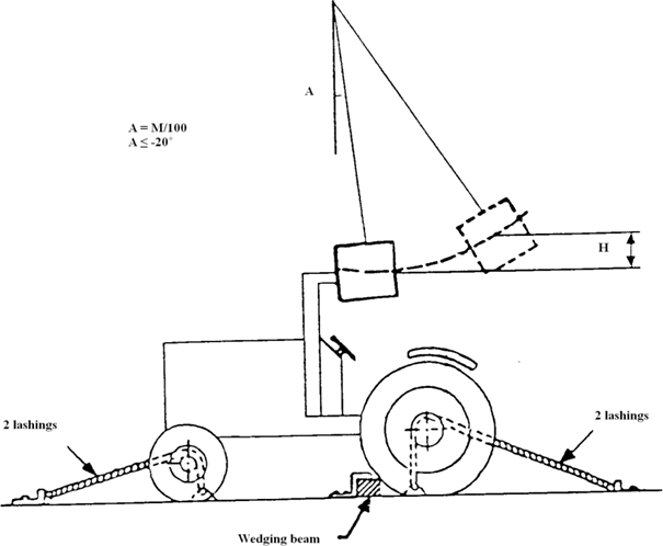
Figure 6.28
Example of tractor lashing (front impact)
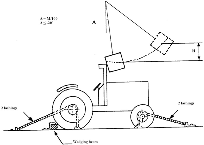
Figure 6.29
Example of tractor lashing (side impact)

B3.REQUIREMENTS FOR FOLDABLE ROPS PERFORMANCEU.K.
5.1. Scope U.K.
This procedure provides minimum performance and tests requirements for front mounted foldable ROPS
5.2.Explanation of terms used in the performance testing:U.K.
5.2.1.
hand-operated foldable ROPS is a front mounted dual pillar protective structure with hand raising/lowering directly managed by the operator (with or without partial assistance).
5.2.2.
automatic foldable ROPS is a front mounted dual pillar protective structure with full assisted raising/lowering operations.
5.2.3.
locking system is a device fitted to lock, by hand or automatically, the ROPS in the raised or lowered positions.
5.2.4.
grasping area is defined by the manufacturer as a portion of the ROPS and/or additional handle fitted to the ROPS where the operator is allowed to carry out the raising/lowering operations.
5.2.5.
accessible part of the grasping area is intended as the area where the ROPS is handled by the operator during the raising/lowering operations. This area shall be defined with regard to the geometric centre of cross sections of the grasping area.
5.2.6.
pinching point is a dangerous point where parts move in relation to each other or to fixed parts in such a way as may cause persons or certain parts of their bodies to be pinched.
5.2.7.
shear point is a dangerous point where parts move along each other or along other parts in such a way as may cause persons or certain parts of their bodies to be pinched or shorn
5.3. Hand-operated foldable ROPS U.K.
5.3.1.Prior conditions for the testU.K.
The manual handling shall be done by a standing operator with one or more grasps on grasping area of the roll-bar. This area has to be designed without sharp edges, sharp angles and rough surfaces likely to cause injury to the operator.
The grasping area shall be clearly and permanently identified (Figure 6.20).
This area could be on one or both sides of the tractor and could be a structural part of the roll-bar or additional handles. In this grasping area the manual handling to raise or lower the roll-bar shall not create shearing, pinching or uncontrollable movement hazards to the operator (Additional requirement).
Three accessible zones with different amount of allowed force are defined with respect to horizontal plane of the ground and the vertical planes tangent to the outer parts of the tractor that limit the position or the displacement of the operator (Figure 6.21).
Zone II
:
accessible zone without forward leaning of the body
Zone III
:
accessible zone with forward leaning of the body
The position and the movement of the operator are limited by obstacles. These are parts of the tractor and are defined by vertical planes tangent to the external edges of the obstacle.
If the operator needs to move the feet during the manual handling of the roll-bar a displacement is allowed either within a parallel plane to the roll-bar trajectory or within just one more parallel plane to the previous one so as to overcome an obstacle. The overall displacement shall be considered as a combination of straits lines parallel and perpendicular to the roll-bar trajectory. A perpendicular displacement is accepted provided that the operator comes closer to the roll-bar. The accessible area shall be considered as the envelope of the different accessible zones (Figure 6.22).
The tractor must be fitted with tyres having the greatest diameter indicated by the manufacturer and the smallest cross-section for tyres of that diameter. The tyres must be inflated to the pressure recommended for field work.
The rear wheels must be set to the narrowest track width; the front wheels must be set as closely as possible to the same track width. If it is possible to have two front track settings which differ equally from the narrowest rear track setting, the wider of these two front track settings must be selected. [In the case of a tractor fitted with tracks, the manufacturer shall define the tracks setting.]
5.3.2.Test procedureU.K.
Aim of the test is to measure the force necessary to raise or lower the roll-bar. The test will be carried out in static condition: no initial movement of the roll-bar. Each measurement of the force necessary to raise or lower the roll-bar shall be made in a direction tangent to the trajectory of the roll-bar and passing through the geometric centre of cross sections of the grasping area.
The grasping area is considered accessible when located within the accessible zones or the envelope of different accessible zones (Figure 6.23).
The force necessary to raise and lower the roll-bar shall be measured in different points that are within the accessible part of the grasping area (Figure 6.24).
The first measure is carried out at the extremity of the accessible part of the grasping area when the roll-bar is fully lowered (Point A). The second is defined according to the position of Point A after rotation of the roll-bar up to the top of the accessible part of the grasping area (Point A’).
If in the second measure the roll-bar is not fully raised, an additional point shall be measured at the extremity of the accessible part of the grasping area when the roll-bar is fully raised (Point B).
If between the first two measures the trajectory of the first point crosses the limit between Zone I and Zone II a measurement shall be made at this crossing point (Point A'').
In order to measure the force in the required points, it is possible either to measure directly the value or to measure the torque needed to raise or lower the roll-bar so as to calculate the force.
5.3.3.Condition of acceptanceU.K.
5.3.3.1.Force requirementU.K.
The force acceptable for the actuation of the ROPS depends on the accessible zone as shown in Table 6.2.
Table 6.2
Allowed forces
| Zone | I | II | III |
|---|
| Acceptable force (N) | 100 | 75 | 50 |
An increase of no more than 25 % of these acceptable forces is allowed when the roll-bar is fully lowered and fully raised.
An increase of no more than 50 % of these acceptable forces is allowed in the lowering operation.
5.3.3.2.Additional requirementU.K.
The manual handling to raise or lower the roll-bar shall not create shearing, pinching or uncontrollable movement hazards to the operator
A pinching point is not considered dangerous for the operator hands part if in the grasping area the safety distances between the roll-bar and fixed parts of the tractor are no less than 100 mm for hand, wrist, fist and 25 mm for finger (ISO 13854:1996). The safety distances shall be checked with respect to the mode of handling foreseen by the manufacturer in the operator’s manual.
5.4. Hand locking system U.K.
The device fitted to lock the ROPS in the upright/lowered position must be designed:
to be handled by one standing operator and located in one of the accessible zones;
to be hardly separated from the ROPS (for example captive pins as locking pins or retaining pins);
to avoid any confusion in the locking operation (the proper location of the pins shall be indicated);
to avoid unintentional removing or losing of parts.
If the devices employed to lock the ROPS in the upright/lowered position are pins they shall be inserted or removed freely. If to do this there is a need to apply a force on the roll-bar this shall comply with the requirements of points A and B (see point 5.3).
For all other locking devices, they shall be engineered according to an ergonomic approach for what concerns the shape and the force especially avoiding pinching or shearing hazards.
5.5. Preliminary test of automatic locking system U.K.
An automatic locking system fitted on hand-operated foldable ROPS shall be submitted to a preliminary test before the ROPS strength test.
The roll-bar shall be moved from the lower position to the upright locked position and back. These operations correspond to one cycle. 500 cycles shall be completed.
This could be done manually or with the use of external energy (hydraulic, pneumatic or electric actuators). In both cases the force shall be applied within a plane parallel to the trajectory of the roll-bar and passing through the grasping area, the angular speed of the roll-bar shall be roughly constant and less than 20 deg/s.
After the 500 cycles, the force applied when the roll-bar is in the upright position shall not exceed by more than 50 % the allowed force (Table 6.2).
The unlocking of the roll-bar shall be done following the operator manual.
After the completion of the 500 cycles there shall be no maintenance or adjustment on the locking system,
Note 1:The preliminary test could be applied to automatic foldable ROPS systems as well. The test should be carried out before the ROPS strength test.U.K.
Note 2:The preliminary test could be carried out by the manufacturer. In such a case the manufacturer shall provide the test station with a certificate stating that the test has been done according the test procedure and that there were no maintenance or adjustment on the locking system after the completion of the 500 cycles. The test station will check the performance of the device with one cycle from the lower position to the upright locked position and back.U.K.
Figure 6.20
Grasping area
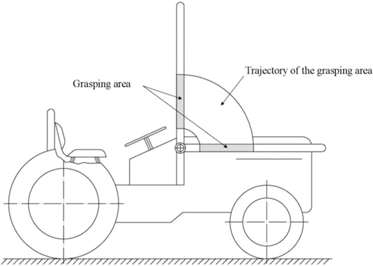
Figure 6.21
Accessible zones
(Dimensions in mm)
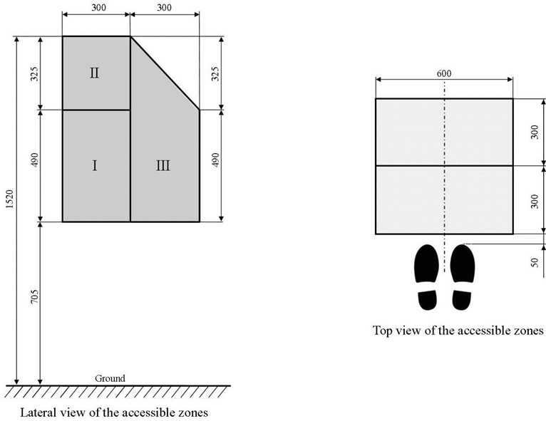
Figure 6.22
Envelope of the accessible zones
(Dimensions in mm)
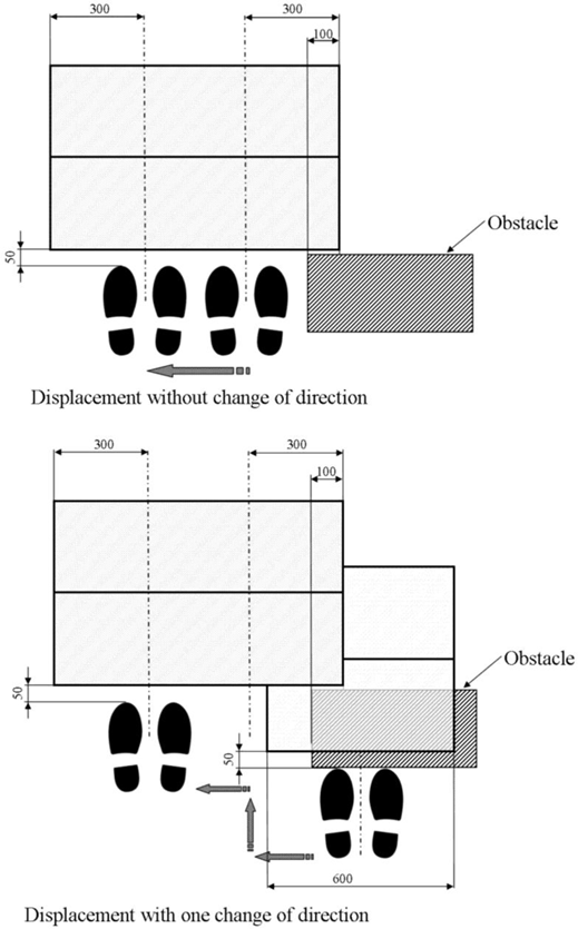
Figure 6.23
Accessible part of the grasping area
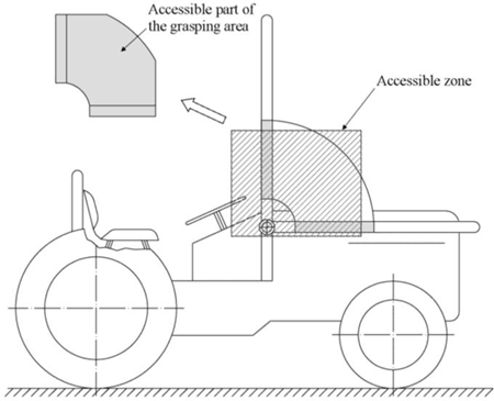
Figure 6.24
Points where the force requirement shall be measured
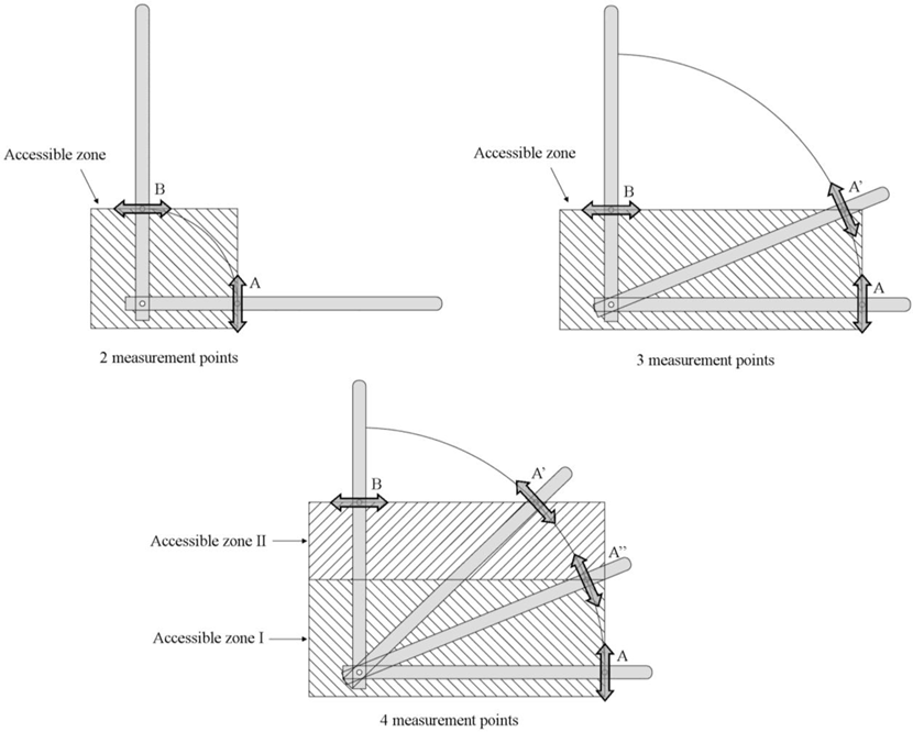
B4.REQUIREMENTS FOR VIRTUAL TESTINGU.K.
Computer programme(3) (BASIC) for determining the continuous or interrupted roll over behaviour in case of a laterally overturning narrow track tractor with a protective frame mounted in front of the driver’s seat U.K.
Preliminary note:U.K.
The following programme is valid for its calculation methods. Presentation of the printed text as proposed (English language and layout) is indicative; the user will adapt the programme to available printing and other requirements specific to the testing station.
10 CLS
20 REM REFERENCE OF THE PROGRAM COD6ABAS.BAS 08/02/96
30 FOR I = 1 TO 10: LOCATE I, 1, 0: NEXT I
40 COLOR 14, 8, 4
50 PRINT "************************************************************************************"
60 PRINT "* CALCULATION FOR DETERMINING THE NON-CONTINUOUS ROLLING BEHAVIOUR *"
70 PRINT "*OF A LATERAL OVERTURNING NARROW TRACTOR WITH A ROLL-OVER PROTECTIVE *"
80 PRINT "* STRUCTURE MOUNTED IN FRONT OF THE DRIVER’S SEAT *"
90 PRINT "************************************************************************************"
100 A$ = INKEY$: IF A$ = "" THEN 100
110 COLOR 10, 1, 4
120 DIM F(25), C(25), CAMPO$(25), LON(25), B$(25), C$(25), X(6, 7), Y(6, 7), Z(6, 7)
130 DATA 6,10,10,14,14,17,19,21,11,11,12,12,13,13,14,14,15,15,16,16,17,17,18,18,19
140 DATA 54,8,47,8,47,12,8,12,29,71,29,71,29,71,29,71,29,71,29,71,29,71,29,71,29
150 DATA 12,30,31,30,31,25,25,25,9,9,9,9,9,9,9,9,9,9,9,9,9,9,9,9,9
160 FOR I = 1 TO 25: READ F(I): NEXT
170 FOR I = 1 TO 25: READ C(I): NEXT
180 FOR I = 1 TO 25: READ LON(I): NEXT
190 CLS
200 FOR I = 1 TO 5: LOCATE I, 1, 0: NEXT I
210 PRINT "In case of misprint, push on the enter key up to the last field"
220 PRINT :LOCATE 6, 44: PRINT " TEST NR: ": PRINT
230 LOCATE 8, 29: PRINT " FRONT MOUNTED- PROTECTIVE STRUCTURE:": PRINT
240 PRINT " MAKE: ": LOCATE 10, 40: PRINT " TYPE: ": PRINT
250 LOCATE 12, 29: PRINT " TRACTOR :": PRINT : PRINT " MAKE:"
260 LOCATE 14, 40: PRINT " TYPE: ": PRINT : PRINT
270 PRINT " LOCATION: ": PRINT
280 PRINT " DATE: ": PRINT : PRINT " ENGINEER:"
290 NC = 1: GOSUB 4400
300 PRINT : PRINT : PRINT " In case of misprint, it is possible to acquire the data again"
310 PRINT : INPUT " Do you wish to acquire again the data ? (Y/N)"; Z$
320 IF Z$ = "Y" OR Z$ = "y" THEN 190
330 IF Z$ = "N" OR Z$ = "n" THEN 340
340 FOR I=1 TO 3:LPRINT : NEXT: LPRINT ; " TEST NR: "; TAB(10); CAMPO$(1)
350 LPRINT : LPRINT TAB(24); " FRONT MOUNTED PROTECTIVE STRUCTURE:"
360 LL = LEN(CAMPO$(2) + CAMPO$(3))
370 LPRINT TAB(36 - LL / 2); CAMPO$(2) + " - " + CAMPO$(3) : LPRINT
380 LPRINT TAB(32); " OF THE NARROW TRACTOR": LL = LEN(CAMPO$(4) + CAMPO$(5))
390 LPRINT TAB(36 - LL / 2); CAMPO$(4) + " - " + CAMPO$(5) : LPRINT
400 CLS
410 PRINT "In case of mistype, push on the enter key up to the last field"
420 PRINT
430 FOR I = 1 TO 7: LOCATE I, 1, 0: NEXT
440 LOCATE 8, 1: PRINT " CHARACTERISTIC UNITS:"
450 LOCATE 8, 29: PRINT "LINEAR (m): MASS (kg):MOMENT OF INERTIA (kg×m2):"
460 LOCATE 9, 1: PRINT " ANGLE (radian)"
470 LPRINT : PRINT
480 PRINT "HEIGHT OF COG H1=": LOCATE 11, 29: PRINT""
490 LOCATE 11, 40: PRINT "H. DIST. COG-REAR AXLE L3="
500 LOCATE 11, 71: PRINT""
510 PRINT "H. DIST. COG-FRT AXLE L2=": LOCATE 12, 29: PRINT""
520 LOCATE 12, 40: PRINT "HEIGHT OF THE REAR TYRES D3="
530 LOCATE 12, 71: PRINT""
540 PRINT "HEIGHT OF THE FRT TYRES D2=": LOCATE 13, 29: PRINT""
550 LOCATE 13, 40: PRINT "OVERALL HEIGHT(PT IMPACT) H6="
560 LOCATE 13, 71: PRINT""
570 PRINT "H.DIST.COG-LEAD.PT INTER.L6=": LOCATE 14, 29: PRINT""
580 LOCATE 14, 40: PRINT "PROTECTIVE STRUCT. WIDTH B6="
590 LOCATE 14, 71: PRINT""
600 PRINT "HEIGHT OF THE ENG.B. H7=": LOCATE 15, 29: PRINT""
605 LOCATE 15, 40: PRINT "WIDTH OF THE ENG. B. B7="
610 LOCATE 15, 71: PRINT""
615 PRINT "H.DIST.COG-FRT COR.ENG.B.L7=": LOCATE 16, 29: PRINT""
620 LOCATE 16, 40: PRINT "HEIGHT FRT AXLE PIVOT PT H0="
630 LOCATE 16, 71: PRINT""
640 PRINT "REAR TRACK WIDTH S =": LOCATE 17, 29: PRINT""
650 LOCATE 17, 40: PRINT "REAR TYRE WIDTH B0="
660 LOCATE 17, 71: PRINT""
670 PRINT "FRT AXLE SWING ANGLE D0=": LOCATE 18, 29: PRINT""
680 LOCATE 18, 40: PRINT "TRACTOR MASS Mc ="
690 LOCATE 18, 71: PRINT""
700 PRINT "MOMENT OF INERTIA Q =": LOCATE 19, 29: PRINT""
710 LOCATE 19, 40: PRINT""
720 LOCATE 19, 71: PRINT " ": PRINT : PRINT
730 H1 = 0: L3 = 0: L2 = 0: D3 = 0: D2 = 0: H6 = 0: L6 = 0: B6 = 0
740 H7 = 0: B7 = 0: L7 = 0: H0 = 0: S = 0: B0 = 0: D = 0: Mc = 0: Q = 0
750 NC = 9: GOSUB 4400
760 FOR I = 1 TO 3: PRINT "": NEXT
770 H1 = VAL(CAMPO$(9)): L3 = VAL(CAMPO$(10)): L2 = VAL(CAMPO$(11))
780 D3 = VAL(CAMPO$(12)): D2 = VAL(CAMPO$(13)): H6 = VAL(CAMPO$(14))
790 L6 = VAL(CAMPO$(15)): B6 = VAL(CAMPO$(16)): H7 = VAL(CAMPO$(17))
800 B7 = VAL(CAMPO$(18)): L7 = VAL(CAMPO$(19)): H0 = VAL(CAMPO$(20))
810 S = VAL(CAMPO$(21)): B0 = VAL(CAMPO$(22)): D0 = VAL(CAMPO$(23))
820 Mc = VAL(CAMPO$(24)): Q = VAL(CAMPO$(25)): PRINT : PRINT
830 PRINT "In case of mistype, it is possible to acquire again the data": PRINT
840 INPUT " Do you wish to acquire again the data ? (Y/N)"; X$
850 IF X$ = "Y" OR X$ = "y" THEN 400
860 IF X$ = "n" OR X$ = "N" THEN 870
870 FOR I = 1 TO 3: LPRINT : NEXT
880 LPRINT TAB(20); "CHARACTERISTIC UNITS :": LOCATE 8, 29
890 LPRINT "LINEAR (m) : MASS (kg) : MOMENT OF INERTIA (kg×m2) : ANGLE (radian)"
900 LPRINT
910 LPRINT "HEIGHT OF THE COG H1=";
920 LPRINT USING"####.####"; H1;
930 LPRINT TAB(40); "H. DIST. COG-REAR AXLE L3=";
940 LPRINT USING"####.####"; L3
950 LPRINT "H.DIST. COG-FRT AXLE L2=";
960 LPRINT USING"####.####"; L2;
970 LPRINT TAB(40); "HEIGHT OF THE REAR TYRES D3=";
975 LPRINT USING"####.####"; D3
980 LPRINT "HEIGHT OF THE FRT TYRES D2=";
990 LPRINT USING"####.####"; D2;
1000 LPRINT TAB(40); "OVERALL HEIGHT(PT IMPACT)H6=";
1010 LPRINT USING"####.####"; H6
1020 LPRINT "H.DIST.COG-LEAD PT INTER.L6=";
1030 LPRINT USING"####.####"; L6;
1040 LPRINT TAB(40); "PROTECTIVE STRUCT. WIDTH B6=";
1050 LPRINT USING"####.####"; B6
1060 LPRINT "HEIGHT OF THE ENG.B. H7=";
1070 LPRINT USING"####.####"; H7;
1080 LPRINT TAB(40); "WIDTH OF THE ENG. B. B7=";
1090 LPRINT USING"####.####"; B7
1100 LPRINT "H.DIST.COG-FRT COR.ENG.B.L7=";
1110 LPRINT USING"####.####"; L7;
1120 LPRINT TAB(40); "HEIGHT FRT AXLE PIVOT PT H0=";
1130 LPRINT USING"####.####"; H0
1140 LPRINT "REAR TRACK WIDTH S =";
1150 LPRINT USING"####.####"; S;
1160 LPRINT TAB(40); "REAR TYRE WIDTH B0=";
1170 LPRINT USING"####.####"; B0
1180 LPRINT "FRT AXLE SWING ANGLE D0=";
1185 LPRINT USING"####.####"; D0;
1190 LPRINT TAB(40); "TRACTOR MASS Mc = ";
1200 LPRINT USING "####.###"; Mc
1210 LPRINT "MOMENT OF INERTIA Q =";
1215 LPRINT USING"####.####"; Q
1220 FOR I = 1 TO 10: LPRINT : NEXT
1230 A0 = .588: U = .2: T = .2: GOSUB 4860
1240 REM * THE SIGN OF L6 IS MINUS IF THE POINT LIES IN FRONT
1250 REM * OF THE PLANE OF THE CENTRE OF GRAVITY.
1260 IF B6 > S + B0 THEN 3715
1265 IF B7 > S + B0 THEN 3715
1270 G = 9.8
1280 REM ***************************************************************************
1290 REM *B2 VERSION (POINT OF IMPACT OF THE ROPS NEAR OF EQUILIBRIUM POINT)*
1300 REM ***************************************************************************
1310 B = B6: H = H6
1320 REM POSITION OF CENTER OF GRAVITY IN TILTED POSITION
1330 R2 = SQR(H1 * H1 + L3 * L3)
1340 C1 = ATN(H1 / L3)
1350 L0 = L3 + L2
1360 L9 = ATN(H0 / L0)
1370 H9 = R2 * SIN(C1 - L9)
1380 W1 = H9 / TAN(C1 - L9)
1390 W2 = SQR(H0 * H0 + L0 * L0): S1 = S / 2
1400 F1 = ATN(S1 / W2)
1410 W3 = (W2 - W1) * SIN(F1)
1420 W4 = ATN(H9 / W3)
1430 W5 = SQR(H9 * H9 + W3 * W3) * SIN(W4 + D0)
1440 W6 = W3 - SQR(W3 * W3 + H9 * H9) * COS(W4 + D0)
1450 W7 = W1 + W6 * SIN(F1)
1460 W8 = ATN(W5 / W7)
1470 W9 = SIN(W8 + L9) * SQR(W5 * W5 + W7 * W7)
1480 W0 = SQR(W9 * W9 + (S1 - W6 * COS(F1)) ^ 2)
1490 G1 = SQR(((S + B0) / 2) ^ 2 + H1 * H1)
1500 G2 = ATN(2 * H1 / (S + B0))
1510 G3 = W0 - G1 * COS(A0 + G2)
1520 O0 = SQR(2 * Mc * G * G3 / (Q + Mc * (W0 + G1) * (W0 + G1) / 4))
1530 F2 = ATN(((D3 - D2) / L0) / (1 - ((D3 - D2) / (2 * L3 + 2 * L2)) ^ 2))
1540 L8 = -TAN(F2) * (H - H1)
1550 REM COORDINATES IN POSITION 1
1560 X(1, 1) = H1
1570 X(1, 2) = 0: X(1, 3) = 0
1580 X(1, 4) = (1 + COS(F2)) * D2 / 2
1590 X(1, 5) = (1 + COS(F2)) * D3 / 2
1600 X(1, 6) = H
1610 X(1, 7) = H7
1620 Y(1, 1) = 0
1630 Y(1, 2) = L2
1640 Y(1, 3) = -L3
1650 Y(1, 4) = L2 + SIN(F2) * D2 / 2
1660 Y(1, 5) = -L3 + SIN(F2) * D3 / 2
1670 Y(1, 6) = -L6
1680 Y(1, 7) = L7
1690 Z(1, 1) = (S + B0) / 2
1700 Z(1, 2) = 0: Z(1, 3) = 0: Z(1, 4) = 0: Z(1, 5) = 0
1710 Z(1, 6) = (S + B0) / 2 - B / 2
1720 Z(1, 7) = (S + B0) / 2 - B7 / 2
1730 O1 = 0: O2 = 0: O3 = 0: O4 = 0: O5 = 0: O6 = 0: O7 = 0: O8 = 0: O9 = 0
1740 K1 = Y(1, 4) * TAN(F2) + X(1, 4)
1750 K2 = X(1, 1)
1760 K3 = Z(1, 1)
1770 K4 = K1 - X(1, 1): DD1 = Q + Mc * K3 * K3 + Mc * K4 * K4
1780 O1 = (Q + Mc * K3 * K3 - U * Mc * K4 * K4 - (1 + U) * Mc * K2 * K4) * O0 / DD1
1790 REM TRANSFORMATION OF THE COORDINATES FROM THE POSITION 1 TO 2
1800 FOR K = 1 TO 7 STEP 1
1810 X(2, K) = COS(F2) * (X(1, K) - H1) + SIN(F2) * Y(1, K) - K4 * COS(F2)
1820 Y(2, K) = Y(1, K) * COS(F2) - (X(1, K) - H1) * SIN(F2)
1830 Z(2, K) = Z(1, K)
1840 NEXT K
1850 O2 = O1 * COS(F2)
1860 A2 = ATN(TAN(A0) / SQR(1 + (TAN(F2)) ^ 2 / (COS(A0)) ^ 2))
1870 C2 = ATN(Z(2, 6) / X(2, 6))
1880 T2 = T
1890 V0 = SQR(X(2, 6) ^ 2 + Z(2, 6) ^ 2)
1900 E1 = T2 / V0
1910 E2 = (V0 * Y(2, 4)) / (Y(2, 4) - Y(2, 6))
1920 T3 = E1 * E2
1930 E4 = SQR(X(2, 1) * X(2, 1) + Z(2, 1) * Z(2, 1))
1940 V6 = ATN(X(2, 1) / Z(2, 1))
1950 REM ROTATION OF THE TRACTOR FROM THE POSITION 2 TO 3
1960 FOR K = 1 TO 7 STEP 1
1970 IF Z(2, K) = 0 THEN 2000
1980 E3 = ATN(X(2, K) / Z(2, K))
1990 GOTO 2010
2000 E3 = -3.14159 / 2
2010 X(3, K) = SQR(X(2, K) * X(2, K) + Z(2, K) * Z(2, K)) * SIN(E3 + C2 + E1)
2020 Y(3, K) = Y(2, K)
2030 Z(3, K) = SQR(X(2, K) ^ 2 + Z(2, K) ^ 2) * COS(E3 + C2 + E1)
2040 NEXT K
2050 IF Z(3, 7) < 0 THEN 3680
2060 Z(3, 6) = 0
2070 Q3 = Q * (COS(F2)) ^ 2 + 3 * Q * (SIN(F2)) ^ 2
2080 V5 = (Q3 + Mc * E4 * E4) * O2 * O2 / 2
2090 IF -V6 > A2 THEN 2110
2100 GOTO 2130
2110 V7 = E4 * (1 - COS(-A2 - V6))
2120 IF V7 * Mc * G > V5 THEN 2320
2130 V8 = E4 * COS(-A2 - V6) - E4 * COS(-A2 - ATN(X(3, 1) / Z(3, 1)))
2140 O3 = SQR(2 * Mc * G * V8 / (Q3 + Mc * E4 * E4) + O2 * O2)
2150 K9 = X(3, 1)
2160 K5 = Z(3, 1)
2170 K6 = Z(3, 1) + E1 * V0
2180 K7 = V0 - X(3, 1)
2190 K8 = U: DD2 = Q3 + Mc * K6 * K6 + Mc * K7 * K7
2200 O4 = (Q3 + Mc * K5 * K6 - K8 * Mc * K7 * K7 - (1 + K8) * Mc * K9 * K7) * O3 / DD2
2210 N3 = SQR((X(3, 6) - X(3, 1)) ^ 2 + (Z(3, 6) - Z(3, 1)) ^ 2)
2220 N2 = ATN(-(X(3, 6) - X(3, 1)) / Z(3, 1))
2230 Q6 = Q3 + Mc * N3 ^ 2
2240 IF -N2 <= A2 THEN 2290
2250 N4 = N3 * (1 - COS(-A2 - N2))
2260 N5 = (Q6) * O4 * O4 / 2
2270 IF N4 * Mc * G > N5 THEN 2320
2280 O9 = SQR(-2 * Mc * G * N4 / (Q6) + O4 * O4)
2290 GOSUB 3740
2300 GOSUB 4170
2310 GOTO 4330
2320 GOSUB 3740
2330 IF L6 > L8 THEN 2790
2340 REM *
2350 REM ***************************************************************************************
2355 REM *B3 VERSION (POINT OF IMPACT OF THE ROPS IN FRONT OF EQUILIBRIUM POINT)*
2360 REM ***************************************************************************************
2370 O3 = 0: O4 = 0: O5 = 0: O6 = 0: O7 = 0: O8 = 0: O9 = 0
2380 E2 = (V0 * Y(2, 5)) / (Y(2, 5) - Y(2, 6))
2390 T3 = E2 * E1
2400 Z(3, 6) = 0
2410 Q3 = Q * (COS(F2)) ^ 2 + 3 * Q * (SIN(F2)) ^ 2
2420 V5 = (Q3 + Mc * E4 * E4) * O2 * O2 / 2
2430 IF -V6 > A2 THEN 2450
2440 GOTO 2470
2450 V7 = E4 * (1 - COS(-A2 - V6))
2460 IF V7 * Mc * G > V5 THEN 2760
2470 V8 = E4 * COS(-A2 - V6) - E4 * COS(-A2 - ATN(X(3, 1) / Z(3, 1)))
2480 O3 = SQR((2 * Mc * G * V8) / (Q3 + Mc * E4 * E4) + O2 * O2)
2490 K9 = X(3, 1)
2500 K5 = Z(3, 1)
2510 K6 = Z(3, 1) + T3
2520 K7 = E2 - X(3, 1)
2530 K8 = U: DD2 = Q3 + Mc * K6 * K6 + Mc * K7 * K7
2540 O4 = (Q3 + Mc * K5 * K6 - K8 * Mc * K7 * K7 - (1 + K8) * Mc * K9 * K7) * O3 / DD2
2550 F3 = ATN(V0 / (Y(3, 5) - Y(3, 6)))
2560 O5 = O4 * COS(F3)
2570 REM TRANSFORMATION OF THE COORDINATES FROM THE POSITION 3 TO 4
2580 REM POSITION 4
2590 FOR K = 1 TO 7 STEP 1
2600 X(4, K) = X(3, K) * COS(F3) + (Y(3, K) - Y(3, 5)) * SIN(F3)
2610 Y(4, K) = (Y(3, K) - Y(3, 5)) * COS(F3) - X(3, K) * SIN(F3)
2620 Z(4, K) = Z(3, K)
2630 NEXT K
2640 A4 = ATN(TAN(A0) / SQR(1 + (TAN(F2 + F3)) ^ 2 / (COS(A0)) ^ 2))
2650 M1 = SQR(X(4, 1) ^ 2 + Z(4, 1) ^ 2)
2660 M2 = ATN(X(4, 1) / Z(4, 1))
2670 Q5 = Q * (COS(F2 + F3)) ^ 2 + 3 * Q * (SIN(F2 + F3)) ^ 2
2680 IF -M2 < A4 THEN 2730
2690 M3 = M1 * (1 - COS(-A4 - M2))
2700 M4 = (Q5 + Mc * M1 * M1) * O5 * O5 / 2
2710 IF M3 * Mc * G > M4 THEN 2760
2720 O9 = SQR(O5 * O5 - 2 * Mc * G * M3 / (Q5 + Mc * M1 * M1))
2730 GOSUB 3740
2740 GOSUB 4170
2750 GOTO 4330
2760 GOSUB 3740
2770 GOSUB 4240
2780 GOTO 4330
2790 REM ****************************************************************************************
2795 REM *B1 VERSION (POINT OF IMPACT OF THE ROPS BEHIND OF EQUILIBRIUM POINT)*
2800 REM ****************************************************************************************
2810 REM *
2820 O3 = 0: O4 = 0: O5 = 0: O6 = 0: O7 = 0: O8 = 0: O9 = 0
2830 Z(3, 6) = 0
2840 Q3 = Q * (COS(F2)) ^ 2 + 3 * Q * (SIN(F2)) ^ 2
2850 V5 = (Q3 + Mc * E4 * E4) * O2 * O2 / 2
2860 IF -V6 > A2 THEN 2880
2870 GOTO 2900
2880 V7 = E4 * (1 - COS(-A2 - V6))
2890 IF V7 * Mc * G > V5 THEN 3640
2900 V8 = E4 * COS(-A2 - V6) - E4 * COS(-A2 - ATN(X(3, 1) / Z(3, 1)))
2910 O3 = SQR(2 * Mc * G * V8 / (Q3 + Mc * E4 * E4) + O2 * O2)
2920 K9 = X(3, 1)
2930 K5 = Z(3, 1)
2940 K6 = Z(3, 1) + T3
2950 K7 = E2 - X(3, 1)
2960 K8 = U: DD2 = Q3 + Mc * K6 * K6 + Mc * K7 * K7
2970 O4 = (Q3 + Mc * K5 * K6 - K8 * Mc * K7 * K7 - (1 + K8) * Mc * K9 * K7) * O3 / DD2
2980 F3 = ATN(V0 / (Y(3, 4) - Y(3, 6)))
2990 O5 = O4 * COS(F3)
3000 REM TRANSFORMATION OF THE COORDINATES FROM 3 TO 4
3010 FOR K = 1 TO 7 STEP 1
3020 X(4, K) = X(3, K) * COS(F3) + (Y(3, K) - Y(3, 4)) * SIN(F3)
3030 Y(4, K) = (Y(3, K) - Y(3, 4)) * COS(F3) - X(3, K) * SIN(F3)
3040 Z(4, K) = Z(3, K)
3050 NEXT K
3060 A4 = ATN(TAN(A0) / SQR(1 + (TAN(F2 + F3)) ^ 2 / (COS(A0)) ^ 2))
3070 C3 = ATN(Z(4, 7) / X(4, 7))
3080 C4 = 0
3090 C5 = SQR(X(4, 7) * X(4, 7) + Z(4, 7) * Z(4, 7))
3100 C6 = C4 / C5
3110 C7 = C5 * (Y(4, 6) - Y(4, 1)) / (Y(4, 6) - Y(4, 7))
3120 C8 = C6 * C7
3130 M1 = SQR(X(4, 1) ^ 2 + Z(4, 1) ^ 2)
3140 M2 = ATN(X(4, 1) / Z(4, 1))
3150 REM ROTATION OF THE TRACTOR FROM THE POSITION 4 TO 5
3160 FOR K = 1 TO 7 STEP 1
3170 IF Z(4, K) <> 0 THEN 3200
3180 C9 = -3.14159 / 2
3190 GOTO 3210
3200 C9 = ATN(X(4, K) / Z(4, K))
3210 X(5, K) = SQR(X(4, K) ^ 2 + Z(4, K) ^ 2) * SIN(C9 + C3 + C6)
3220 Y(5, K) = Y(4, K)
3230 Z(5, K) = SQR(X(4, K) ^ 2 + Z(4, K) ^ 2) * COS(C9 + C3 + C6)
3240 NEXT K
3250 Z(5, 7) = 0
3260 Q5 = Q * (COS(F2 + F3)) ^ 2 + 3 * Q * (SIN(F2 + F3)) ^ 2
3270 IF -M2 > A4 THEN 3290
3280 GOTO 3320
3290 M3 = M1 * (1 - COS(-A4 - M2))
3300 M4 = (Q5 + Mc * M1 * M1) * O5 * O5 / 2
3310 IF M3 * Mc * G > M4 THEN 3640
3315 MM1 = M1 * COS(-A4 - ATN(X(5, 1) / Z(5, 1)))
3320 M5 = M1 * COS(-A4 - ATN(X(4, 1) / Z(4, 1))) - MM1
3330 O6 = SQR(2 * Mc * G * M5 / (Q5 + Mc * M1 * M1) + O5 * O5)
3340 M6 = X(5, 1)
3350 M7 = Z(5, 1)
3360 M8 = Z(5, 1) + C8
3370 M9 = C7 - X(5, 1)
3380 N1 = U: DD3 = (Q5 + Mc * M8 * M8 + Mc * M9 * M9)
3390 O7 = (Q5 + Mc * M7 * M8 - N1 * Mc * M9 * M9 - (1 + N1) * Mc * M6 * M9) * O6 / DD3
3400 F5 = ATN(C5 / (Y(5, 6) - Y(5, 7)))
3410 A6 = ATN(TAN(A0) / SQR(1 + (TAN(F2 + F3 + F5)) ^ 2 / (COS(A0)) ^ 2))
3420 REM TRANSFORMATION OF THE COORDINATES FROM THE POSITION 5 TO 6
3430 FOR K = 1 TO 7 STEP 1
3440 X(6, K) = X(5, K) * COS(F5) + (Y(5, K) - Y(5, 6)) * SIN(F5)
3450 Y(6, K) = (Y(5, K) - Y(5, 6)) * COS(F5) - X(5, K) * SIN(F5)
3460 Z(6, K) = Z(5, K)
3470 NEXT K
3480 O8 = O7 * COS(-F5)
3490 N2 = ATN(X(6, 1) / Z(6, 1))
3500 N3 = SQR(X(6, 1) ^ 2 + Z(6, 1) ^ 2)
3510 Q6 = Q * (COS(F2 + F3 + F5)) ^ 2 + 3 * Q * (SIN(F2 + F3 + F5)) ^ 2
3520 IF -N2 > A6 THEN 3540
3530 GOTO 3580
3540 N4 = N3 * (1 - COS(-A6 - N2))
3550 N5 = (Q6 + Mc * N3 * N3) * O8 * O8 / 2
3560 P9 = (N4 * Mc * G - N5) / (N4 * Mc * G)
3570 IF N4 * Mc * G > N5 THEN 3640
3580 IF -N2 < A6 THEN 3610
3590 N6 = -N4
3600 O9 = SQR(2 * Mc * G * N6 / (Q6 + Mc * N3 * N3) + O8 * O8)
3610 GOSUB 3740
3620 GOSUB 4170
3630 GOTO 4330
3640 GOSUB 3740
3650 GOSUB 4240
3660 GOTO 4330
3670 REM
3680 IF Z(3, 7) > -.2 THEN 2060
3685 CLS : PRINT : PRINT : PRINT STRING$(80, 42): LOCATE 24, 30, 0
3690 PRINT "THE ENGINE BONNET TOUCHES THE GROUND BEFORE THE ROPS"
3695 LPRINT STRING$(80, 42)
3700 LPRINT "THE ENGINE BONNET TOUCHES THE GROUND BEFORE THE ROPS"
3710 PRINT : PRINT "METHOD OF CALCULATION NOT FEASIBLE" : GOTO 3720
3715 CLS : PRINT : PRINT "METHOD OF CALCULATION NOT FEASIBLE"
3720 LPRINT "METHOD OF CALCULATION NOT FEASIBLE"
3725 LPRINT STRING$(80, 42)
3730 GOTO 4330
3740 REM *******************************************************************
3750 CLS : LOCATE 13, 15, 0: PRINT "VELOCITY O0="
3755 LOCATE 13, 31, 0: PRINT USING"#.###"; O0: LOCATE 13, 40, 0: PRINT "rad/s"
3760 LOCATE 14, 15, 0: PRINT "VELOCITY O1="
3765 LOCATE 14, 31, 0: PRINT USING"#.###"; O1
3770 LOCATE 15, 15, 0: PRINT "VELOCITY O2="
3775 LOCATE 15, 31, 0: PRINT USING"#.###"; O2
3780 LOCATE 16, 15, 0: PRINT "VELOCITY O3="
3785 LOCATE 16, 31, 0: PRINT USING"#.###"; O3
3790 LOCATE 17, 15, 0: PRINT "VELOCITY O4="
3795 LOCATE 17, 31, 0: PRINT USING"#.###"; O4
3800 LOCATE 18, 15, 0: PRINT "VELOCITY O5="
3805 LOCATE 18, 31, 0: PRINT USING"#.###"; O5
3810 LOCATE 19, 15, 0: PRINT "VELOCITY O6="
3815 LOCATE 19, 31, 0: PRINT USING"#.###"; O6
3820 LOCATE 20, 15, 0: PRINT "VELOCITY O7="
3825 LOCATE 20, 31, 0: PRINT USING"#.###"; O7
3830 LOCATE 21, 15, 0: PRINT "VELOCITY O8="
3835 LOCATE 21, 31, 0: PRINT USING"#.###"; O8
3840 LOCATE 22, 15, 0: PRINT "VELOCITY O9="
3845 LOCATE 22, 31, 0: PRINT USING"#.###"; O9
3850 LPRINT "VELOCITY O0=";
3860 LPRINT USING"#.###"; O0;
3870 LPRINT " rad/s";
3880 LPRINT TAB(40); "VELOCITY O1=";
3890 LPRINT USING"#.###"; O1;
3900 LPRINT " rad/s"
3910 LPRINT "VELOCITY O2=";
3920 LPRINT USING"#.###"; O2;
3930 LPRINT " rad/s";
3940 LPRINT TAB(40); "VELOCITY O3=";
3950 LPRINT USING"#.###"; O3;
3960 LPRINT " rad/s"
3970 LPRINT "VELOCITY O4=";
3980 LPRINT USING"#.###"; O4;
3990 LPRINT " rad/s";
4000 LPRINT TAB(40); "VELOCITY O5=";
4010 LPRINT USING"#.###"; O5;
4020 LPRINT " rad/s"
4030 LPRINT "VELOCITY O6=";
4040 LPRINT USING"#.###"; O6;
4050 LPRINT " rad/s";
4060 LPRINT TAB(40); "VELOCITY O7=";
4070 LPRINT USING"#.###"; O7;
4080 LPRINT " rad/s"
4090 LPRINT "VELOCITY O8=";
4100 LPRINT USING"#.###"; O8;
4110 LPRINT " rad/s";
4120 LPRINT TAB(40); "VELOCITY O9=";
4130 LPRINT USING"#.###"; O9;
4140 LPRINT " rad/s"
4150 LPRINT
4160 RETURN
4170 PRINT STRING$(80, 42)
4180 LOCATE 24, 30, 0: PRINT "THE TILTING CONTINUES"
4190 PRINT STRING$(80, 42)
4200 LPRINT STRING$(80, 42)
4210 LPRINT TAB(30); "THE TILTING CONTINUES"
4220 LPRINT STRING$(80, 42)
4230 RETURN
4240 PRINT STRING$(80, 42)
4250 LOCATE 24, 30, 0: PRINT "THE ROLLING STOPS"
4260 PRINT STRING$(80, 42)
4270 LPRINT STRING$(80, 42)
4280 LPRINT TAB(30); "THE ROLLING STOPS"
4290 LPRINT STRING$(80, 42)
4300 RETURN
4310 REM *******************************************************************
4320 REM END OF THE CALCULATION
4330 FOR I = 1 TO 5: LPRINT : NEXT: LPRINT " LOCATION : "; CAMPO$(6): LPRINT
4340 LPRINT " DATE : "; CAMPO$(7): LPRINT
4350 LPRINT ; " ENGINEER : "; CAMPO$(8): LPRINT
4360 FOR I = 1 TO 4: LPRINT : NEXT: PRINT
4370 INPUT " Do you whish to carry out another test ? (Y/N)"; Y$
4380 IF Y$ = "Y" OR Y$ = "y" THEN 190
4390 IF Y$ = "N" OR Y$ = "n" THEN SYSTEM
4400 LOCATE F(NC), C(NC) + L, 1: A$ = INKEY$: IF A$ = "" THEN GOTO 4400
4410 IF LEN(A$) > 1 THEN GOSUB 4570: GOTO 4400
4420 A = ASC(A$)
4430 IF A = 13 THEN L = 0: GOTO 4450
4440 GOTO 4470
4450 IF NC < 8 OR NC > 8 AND NC < 25 THEN NC = NC + 1: GOTO 4400
4460 GOTO 4840
4470 IF A > 31 AND A < 183 THEN GOTO 4490
4480 BEEP: GOTO 4400
4490 IF L = LON(NC) THEN BEEP: GOTO 4400
4500 LOCATE F(NC), C(NC) + L: PRINT A$;
4510 L = L + 1
4520 IF L = 1 THEN B$(NC) = A$: GOTO 4540
4530 B$(NC) = B$(NC) + A$
4540 IF LEN(C$(NC)) > 0 THEN C$(NC) = RIGHT$(CAMPO$(NC), LEN(CAMPO$(NC)) - L)
4550 CAMPO$(NC) = B$(NC) + C$(NC)
4560 GOTO 4400
4570 REM * SLIDE
4580 IF LEN(A$) <> 2 THEN BEEP: RETURN
4590 C = ASC(RIGHT$(A$, 1))
4600 IF C = 8 THEN 4620
4610 GOTO 4650
4620 IF LEN(C$(NC)) > 0 THEN BEEP: RETURN
4630 IF L = 0 THEN BEEP: RETURN
4640 CAMPO$(NC) = LEFT$(CAMPO$(NC), LEN(CAMPO(NC)))
4645 L = L - 1: PRINT A$: RETURN
4650 IF C = 30 THEN 4670
4660 GOTO 4700
4670 IF NC = 1 THEN BEEP: RETURN
4680 NC = NC - 1: L = 0
4690 RETURN
4700 IF C = 31 THEN 4720
4710 GOTO 4760
4720 IF NC <> 8 THEN 4740
4730 BEEP: RETURN
4740 NC = NC + 1: L = 0
4750 RETURN
4760 IF C = 29 THEN 4780
4770 GOTO 4800
4780 IF L = 0 THEN BEEP: RETURN
4790 L = L - 1: C$(NC) = RIGHT$(CAMPO$(NC), LEN(CAMPO$(NC)) - (L + 1))
4795 B$(NC) = LEFT$(CAMPO$(NC), L): LOCATE F(NC), C(NC) + L + 1: PRINT ""
4796 RETURN
4800 IF C = 28 THEN 4820
4810 GOTO 4400
4820 IF C$(NC) = "" THEN BEEP: RETURN
4830 L = L + 1: C$(NC) = RIGHT$(CAMPO$(NC), LEN(CAMPO$(NC)) - (L))
4835 B$(NC) = LEFT$(CAMPO$(NC), L): LOCATE F(NC), C(NC) + L, 1: PRINT ""
4840 RETURN
4850 RETURN
4860 FOR II = 1 TO 7
4870 X(1, II) = 0: X(2, II) = 0: X(3, II) = 0
4875 X(4, II) = 0: X(5, II) = 0: X(6, II) = 0
4880 Y(1, II) = 0: Y(2, II) = 0: Y(3, II) = 0
4885 Y(4, II) = 0: Y(5, II) = 0: Y(6, II) = 0
4890 Z(1, II) = 0: Z(2, II) = 0: Z(3, II) = 0
4895 Z(4, II) = 0: Z(5, II) = 0: Z(6, II) = 0
4900 NEXT II
4910 RETURN
4920 REM * THE SYMBOLS USED HERE ARE THE SAME AS IN THE CODE 6.
[For tractor fitted with tracks, the following lines have to be substituted in the original model:
520 LOCATE 12, 40: PRINT ‘ HEIGHT OF THE REAR TRACKS D3= ’
*540 PRINT ‘ HEIGHT OF THE FRT TRACKS D2= ’ : LOCATE 13, 29: PRINT ‘ ’
650 LOCATE 17, 40: PRINT ‘ REAR TRACKS WIDTH B0= ’
970 LPRINT TAB(40); ‘ HEIGHT OF THE REAR TRACKS D3= ’ ;
*980 LPRINT ‘ HEIGHT OF THE FRT TRACKS D2= ’ ;
1160 LPRINT TAB(40); ‘ REAR TRACK WIDTH B0= ’ ;
1390 W2 = SQR(H0 * H0 + L0 * L0): S1 = S/2 + B0/2
1530 F2 = 2 * ATN(- L0/D3 + SQR((L0/D3) ^ 2 – (D2/D3) + 1))
1590 X(1, 5) = D3
1660 Y(1, 5) = -L3
* if applicable] U.K.
Example 6.1 The tilting continues U.K.
TEST NR:
FRONT MOUNTED-OVER PROTECTIVE STRUCTURE OF THE NARROW TRACTOR:U.K.
Characteristic units:
LINEAR (m): MASS (kg):
MOMENT OF INERTIA (kgm2): ANGLE (radian)
| HEIGHT OF THE COG | H1 = 0.7620 | H. DIST. COG-REAR AXLE | L3 = 0.8970 |
| H. DIST. COG - FRONT AXLE | L2 = 1.1490 | HEIGHT OF THE REAR TYRES | D3 = 1.2930 |
| HEIGHT OF THE FRT TYRES | D2 = 0.8800 | OVERALL HEIGHT( PT IMPACT) | H6 = 2.1000 |
| H. DIST. COG-LEAD PT INTER. | L6 = 0.2800 | PROTECTIVE STRUCT. WIDTH | B6 = 0.7780 |
| HEIGHT OF THE ENG. B. | H7 = 1.3370 | WIDTH OF THE ENG. B. | B7 = 0.4900 |
| H. DIST. COG-FRT COR. ENG. B. | L7 = 1.6390 | HEIGHT FRT AXLE PIVOT PT | H0 = 0.4450 |
| REAR TRACK WIDTH | S = 1.1150 | REAR TYRE WIDTH | B0 = 0.1950 |
| FRT AXLE SWING ANGLE | D0 = 0.1570 | TRACTOR MASS | Mc = 2565.000 |
| MOMENT OF INERTIA | Q = 295.0000 | | |
| VELOCITY O0 = 3.881 rad/s | VELOCITY O1 = 1.078 rad/s |
| VELOCITY O2 = 1.057 rad/s | VELOCITY O3 = 2.134 rad/s |
| VELOCITY O4 = 0.731 rad/s | VELOCITY O5 = 0.000 rad/s |
| VELOCITY O6 = 0.000 rad/s | VELOCITY O7 = 0.000 rad/s |
| VELOCITY O8 = 0.000 rad/s | VELOCITY O9 = 0.000 rad/s |
| |
| VELOCITY O0 = 3.881 rad/s | VELOCITY O1 = 1.078 rad/s |
| VELOCITY O2 = 1.057 rad/s | VELOCITY O3 = 2.134 rad/s |
| VELOCITY O4 = 1.130 rad/s | VELOCITY O5 = 0.993 rad/s |
| VELOCITY O6 = 0.810 rad/s | VELOCITY O7 = 0.629 rad/s |
| VELOCITY O8 = 0.587 rad/s | VELOCITY O9 = 0.219 rad/s |
THE TILTING CONTINUES U.K.
Example 6.2 The rolling stops U.K.
TEST NR:
FRONT MOUNTED-OVER PROTECTIVE STRUCTURE OF THE NARROW TRACTOR:U.K.
Characteristic units:
LINEAR (m): MASS (kg):
MOMENT OF INERTIA (kgm2): ANGLE (radian)
| HEIGHT OF THE COG | H1 = 0.7653 | H. DIST. COG-REAR AXLE | L3 = 0.7970 |
| H. DIST. COG - FRONT AXLE | L2 = 1.1490 | HEIGHT OF THE REAR TYRES | D3 = 1.4800 |
| HEIGHT OF THE FRT TYRES | D2 = 0.8800 | OVERALL HEIGHT( PT IMPACT) | H6 = 2.1100 |
| H. DIST. COG-LEAD PT INTER. | L6 = -0.0500 | PROTECTIVE STRUCT. WIDTH | B6 = 0.7000 |
| HEIGHT OF THE ENG. B. | H7 = 1.3700 | WIDTH OF THE ENG. B. | B7 = 0.8000 |
| H. DIST. COG-FRT COR. ENG. B. | L7 = 1.6390 | HEIGHT FRT AXLE PIVOT PT | H0 = 0.4450 |
| REAR TRACK WIDTH | S = 1.1150 | REAR TYRE WIDTH | B0 = 0.1950 |
| FRT AXLE SWING ANGLE | D0 = 0.1570 | TRACTOR MASS | Mc = 1800.000 |
| MOMENT OF INERTIA | Q = 250.0000 | | |
| VELOCITY O0 = 3.840 rad/s | VELOCITY O1 = 0.281 rad/s |
| VELOCITY O2 = 0.268 rad/s | VELOCITY O3 = 1.586 rad/s |
| VELOCITY O4 = 0.672 rad/s | VELOCITY O5 = 0.000 rad/s |
| VELOCITY O6 = 0.000 rad/s | VELOCITY O7 = 0.000 rad/s |
| VELOCITY O8 = 0.000 rad/s | VELOCITY O9 = 0.000 rad/s |
| |
| VELOCITY O0 = 3.840 rad/s | VELOCITY O1 = 0.281 rad/s |
| VELOCITY O2 = 0.268 rad/s | VELOCITY O3 = 1.586 rad/s |
| VELOCITY O4 = 0.867 rad/s | VELOCITY O5 = 0.755 rad/s |
| VELOCITY O6 = 1.218 rad/s | VELOCITY O7= 0.969 rad/s |
| VELOCITY O8 = 0.898 rad/s | VELOCITY O9 = 0.000 rad/s |
THE ROLLING STOPS U.K.
Example 6.3 The rolling stops U.K.
TEST NR:
FRONT MOUNTED-OVER PROTECTIVE STRUCTURE OF THE NARROW TRACTOR:U.K.
Characteristic units:
LINEAR (m): MASS (kg):
MOMENT OF INERTIA (kgm2): ANGLE (radian)
| HEIGHT OF THE COG | H1 = 0.7180 | H. DIST. COG-REAR AXLE | L3 = 0.8000 |
| H. DIST. COG - FRONT AXLE | L2 = 1.1590 | HEIGHT OF THE REAR TYRES | D3 = 1.5200 |
| HEIGHT OF THE FRT TYRES | D2 = 0.7020 | OVERALL HEIGHT( PT IMPACT) | H6 = 2.0040 |
| H. DIST. COG-LEAD PT INTER. | L6 = -0.2000 | PROTECTIVE STRUCT. WIDTH | B6 = 0.6400 |
| HEIGHT OF THE ENG. B. | H7 = 1.2120 | WIDTH OF THE ENG. B. | B7 = 0.3600 |
| H. DIST. COG-FRT COR. ENG. B. | L7 = 1.6390 | HEIGHT FRT AXLE PIVOT PT | H0 = 0.4400 |
| REAR TRACK WIDTH | S = 0.9000 | REAR TYRE WIDTH | B0 = 0.3150 |
| FRT AXLE SWING ANGLE | D0 = 0.1740 | TRACTOR MASS | Mc = 1780.000 |
| MOMENT OF INERTIA | Q = 279.8960 | | |
| VELOCITY O0 = 3.884 rad/s | VELOCITY O1 = 0.107 rad/s |
| VELOCITY O2 = 0.098 rad/s | VELOCITY O3 = 0.000 rad/s |
| VELOCITY O4 = 0.000 rad/s | VELOCITY O5 = 0.000 rad/s |
| VELOCITY O6 = 0.000 rad/s | VELOCITY O7 = 0.000 rad/s |
| VELOCITY O8 = 0.000 rad/s | VELOCITY O9 = 0.000 rad/s |
| |
| VELOCITY O0 = 3.884 rad/s | VELOCITY O1 = 0.107 rad/s |
| VELOCITY O2 = 0.098 rad/s | VELOCITY O3 = 0.000 rad/s |
| VELOCITY O4 = 0.000 rad/s | VELOCITY O5 = 0.000 rad/s |
| VELOCITY O6 = 0.000 rad/s | VELOCITY O7 = 0.000 rad/s |
| VELOCITY O8 = 0.000 rad/s | VELOCITY O9 = 0.000 rad/s |
THE ROLLING STOPS U.K.
Example 6.4 The rolling stops U.K.
TEST NR:
FRONT MOUNTED-OVER PROTECTIVE STRUCTURE OF THE NARROW TRACTOR:U.K.
Characteristic units:
LINEAR (m): MASS (kg):
MOMENT OF INERTIA (kgm2): ANGLE (radian)
| HEIGHT OF THE COG | H1 = 0.7180 | H. DIST. COG-REAR AXLE | L3 = 0.8110 |
| H. DIST. COG - FRONT AXLE | L2 = 1.1590 | HEIGHT OF THE REAR TYRES | D3 = 1.2170 |
| HEIGHT OF THE FRT TYRES | D2 = 0.7020 | OVERALL HEIGHT( PT IMPACT) | H6 = 2.1900 |
| H. DIST. COG-LEAD PT INTER. | L6 = -0.3790 | PROTECTIVE STRUCT. WIDTH | B6 = 0.6400 |
| HEIGHT OF THE ENG. B. | H7 = 1.2120 | WIDTH OF THE ENG. B. | B7 = 0.3600 |
| H. DIST. COG-FRT COR. ENG. B. | L7 = 1.6390 | HEIGHT FRT AXLE PIVOT PT | H0 = 0.4400 |
| REAR TRACK WIDTH | S = 0.9000 | REAR TYRE WIDTH | B0 = 0.3150 |
| FRT AXLE SWING ANGLE | D0 = 0.1740 | TRACTOR MASS | Mc = 1780.000 |
| MOMENT OF INERTIA | Q = 279.8960 | | |
| VELOCITY O0 = 3.884 rad/s | VELOCITY O1 = 1.540 rad/s |
| VELOCITY O2 = 1.488 rad/s | VELOCITY O3 = 2.162 rad/s |
| VELOCITY O4 = 0.405 rad/s | VELOCITY O5 = 0.000 rad/s |
| VELOCITY O6 = 0.000 rad/s | VELOCITY O7 = 0.000 rad/s |
| VELOCITY O8 = 0.000 rad/s | VELOCITY O9 = 0.000 rad/s |
| |
| VELOCITY O0 = 3.884 rad/s | VELOCITY O1 = 1.540 rad/s |
| VELOCITY O2 = 1.488 rad/s | VELOCITY O3 = 2.162 rad/s |
| VELOCITY O4 = 0.414 rad/s | VELOCITY O5 = 0.289 rad/s |
| VELOCITY O6 = 0.000 rad/s | VELOCITY O7= 0.000 rad/s |
| VELOCITY O8 = 0.000 rad/s | VELOCITY O9 = 0.000 rad/s |
THE ROLLING STOPS U.K.
Example 6.5 The tilting continues U.K.
TEST NR:
FRONT MOUNTED-OVER PROTECTIVE STRUCTURE OF THE NARROW TRACTOR:U.K.
Characteristic units:
LINEAR (m): MASS (kg):
MOMENT OF INERTIA (kgm2): ANGLE (radian)
| HEIGHT OF THE COG | H1 = 0.7660 | H. DIST. COG-REAR AXLE | L3 = 0.7970 |
| H. DIST. COG - FRONT AXLE | L2 = 1.1490 | HEIGHT OF THE REAR TYRES | D3 = 1.4800 |
| HEIGHT OF THE FRT TYRES | D2 = 0.8800 | OVERALL HEIGHT( PT IMPACT) | H6 = 2.1100 |
| H. DIST. COG-LEAD PT INTER. | L6 = -0.2000 | PROTECTIVE STRUCT. WIDTH | B6 = 0.7000 |
| HEIGHT OF THE ENG. B. | H7 = 1.3700 | WIDTH OF THE ENG. B. | B7 = 0.8000 |
| H. DIST. COG-FRT COR. ENG. B. | L7 = 1.6390 | HEIGHT FRT AXLE PIVOT PT | H0 = 0.4450 |
| REAR TRACK WIDTH | S = 1.1150 | REAR TYRE WIDTH | B0 = 0.9100 |
| FRT AXLE SWING ANGLE | D0 = 0.1570 | TRACTOR MASS | Mc = 1800.000 |
| MOMENT OF INERTIA | Q = 250.0000 | | |
| VELOCITY O0 = 2.735 rad/s | VELOCITY O1 = 1.271 rad/s |
| VELOCITY O2 = 1.212 rad/s | VELOCITY O3 = 2.810 rad/s |
| VELOCITY O4 = 1.337 rad/s | VELOCITY O5 = 0.000 rad/s |
| VELOCITY O6 = 0.000 rad/s | VELOCITY O7 = 0.000 rad/s |
| VELOCITY O8 = 0.000 rad/s | VELOCITY O9 = 0.000 rad/s |
THE TILTING CONTINUES U.K.
Example 6.6 The tilting continues U.K.
TEST NR:
FRONT MOUNTED-OVER PROTECTIVE STRUCTURE OF THE NARROW TRACTOR:U.K.
Characteristic units:
LINEAR (m): MASS (kg):
MOMENT OF INERTIA (kgm2): ANGLE (radian)
| HEIGHT OF THE COG | H1 = 0.7653 | H. DIST. COG-REAR AXLE | L3 = 0.7970 |
| H. DIST. COG - FRONT AXLE | L2 = 1.1490 | HEIGHT OF THE REAR TYRES | D3 = 1.2930 |
| HEIGHT OF THE FRT TYRES | D2 = 0.8800 | OVERALL HEIGHT( PT IMPACT) | H6 = 1.9600 |
| H. DIST. COG-LEAD PT INTER. | L6 = -0.4000 | PROTECTIVE STRUCT. WIDTH | B6 = 0.7000 |
| HEIGHT OF THE ENG. B. | H7 = 1.3700 | WIDTH OF THE ENG. B. | B7 = 0.8750 |
| H. DIST. COG-FRT COR. ENG. B. | L7 = 1.6390 | HEIGHT FRT AXLE PIVOT PT | H0 = 0.4450 |
| REAR TRACK WIDTH | S = 1.1150 | REAR TYRE WIDTH | B0 = 0.1950 |
| FRT AXLE SWING ANGLE | D0 = 0.1570 | TRACTOR MASS | Mc = 1800.000 |
| MOMENT OF INERTIA | Q = 275.0000 | | |
| VELOCITY O0 = 3.815 rad/s | VELOCITY O1 = 1.130 rad/s |
| VELOCITY O2 = 1.105 rad/s | VELOCITY O3 = 2.196 rad/s |
| VELOCITY O4 = 0.786 rad/s | VELOCITY O5 = 0.000 rad/s |
| VELOCITY O6 = 0.000 rad/s | VELOCITY O7 = 0.000 rad/s |
| VELOCITY O8 = 0.000 rad/s | VELOCITY O9 = 0.000 rad/s |
| |
| VELOCITY O0 = 3.815 rad/s | VELOCITY O1 = 1.130 rad/s |
| VELOCITY O2 = 1.105 rad/s | VELOCITY O3 = 2.196 rad/s |
| VELOCITY O4 = 0.980 rad/s | VELOCITY O5 = 0.675 rad/s |
| VELOCITY O6 = 0.000 rad/s | VELOCITY O7 = 0.000 rad/s |
| VELOCITY O8 = 0.000 rad/s | VELOCITY O9 = 0.548 rad/s |
THE TILTING CONTINUES U.K.
Example 6.7 Method of calculation not feasible U.K.
TEST NR:
FRONT MOUNTED-OVER PROTECTIVE STRUCTURE OF THE NARROW TRACTOR:U.K.
Characteristic units:
LINEAR (m): MASS (kg):
MOMENT OF INERTIA (kgm2): ANGLE (radian)
| HEIGHT OF THE COG | H1 = 0.7620 | H. DIST. COG-REAR AXLE | L3 = 0.7970 |
| H. DIST. COG - FRONT AXLE | L2 = 1.1490 | HEIGHT OF THE REAR TYRES | D3 = 1.5500 |
| HEIGHT OF THE FRT TYRES | D2 = 0.8800 | OVERALL HEIGHT( PT IMPACT) | H6 = 2.1000 |
| H. DIST. COG-LEAD PT INTER. | L6 = -0.4780 | PROTECTIVE STRUCT. WIDTH | B6 = 0.7780 |
| HEIGHT OF THE ENG. B. | H7 = 1.5500 | WIDTH OF THE ENG. B. | B7 = 0.9500 |
| H. DIST. COG-FRT COR. ENG. B. | L7 = 1.6390 | HEIGHT FRT AXLE PIVOT PT | H0 = 0.4450 |
| REAR TRACK WIDTH | S = 1.1150 | REAR TYRE WIDTH | B0 = 0.1950 |
| FRT AXLE SWING ANGLE | D0 = 0.1570 | MOMENT OF INERTIA | Q = 200.0000 |
| TRACTOR MASS | Mc = 1800.000 | | |
THE ENGINE BONNET TOUCHES THE GROUND BEFORE THE ROPS METHOD OF CALCULATION NOT FEASIBLE U.K.
Example 6.8 The rolling stops U.K.
TEST NR:
FRONT MOUNTED-OVER PROTECTIVE STRUCTURE OF THE NARROW TRACTOR:U.K.
Characteristic units:
LINEAR (m): MASS (kg):
MOMENT OF INERTIA (kgm2): ANGLE (radian)
| HEIGHT OF THE COG | H1 = 0.7180 | H. DIST. COG-REAR AXLE | L3 = 0.8110 |
| H. DIST. COG - FRONT AXLE | L2 = 1.1590 | HEIGHT OF THE REAR TYRES | D3 = 1.2170 |
| HEIGHT OF THE FRT TYRES | D2 = 0.7020 | OVERALL HEIGHT( PT IMPACT) | H6 = 2.0040 |
| H. DIST. COG-LEAD PT INTER. | L6 = -0.3790 | PROTECTIVE STRUCT. WIDTH | B6 = 0.6400 |
| HEIGHT OF THE ENG. B. | H7 = 1.2120 | WIDTH OF THE ENG. B. | B7 = 0.3600 |
| H. DIST. COG-FRT COR. ENG. B. | L7 = 1.6390 | HEIGHT FRT AXLE PIVOT PT | H0 = 0.4400 |
| REAR TRACK WIDTH | S = 0.9000 | REAR TYRE WIDTH | B0 = 0.3150 |
| FRT AXLE SWING ANGLE | D0 = 0.1740 | TRACTOR MASS | Mc = 1780.000 |
| MOMENT OF INERTIA | Q = 279.8960 | | |
| VELOCITY O0 = 3.884 rad/s | VELOCITY O1 = 1.540 rad/s |
| VELOCITY O2 = 1.488 rad/s | VELOCITY O3 = 2.313 rad/s |
| VELOCITY O4 = 0.581 rad/s | VELOCITY O5 = 0.000 rad/s |
| VELOCITY O6 = 0.000 rad/s | VELOCITY O7 = 0.000 rad/s |
| VELOCITY O8 = 0.000 rad/s | VELOCITY O9 = 0.000 rad/s |
| |
| VELOCITY O0 = 3.884 rad/s | VELOCITY O1 = 1.540 rad/s |
| VELOCITY O2 = 1.488 rad/s | VELOCITY O3 = 2.313 rad/s |
| VELOCITY O4 = 0.633 rad/s | VELOCITY O5 = 0.373 rad/s |
| VELOCITY O6 = 0.000 rad/s | VELOCITY O7 = 0.000 rad/s |
| VELOCITY O8 = 0.000 rad/s | VELOCITY O9 = 0.000 rad/s |
THE ROLLING STOPS U.K.
Example 6.9 The tilting continues U.K.
TEST NR:
FRONT MOUNTED-OVER PROTECTIVE STRUCTURE OF THE NARROW TRACTOR:U.K.
Characteristic units:
LINEAR (m): MASS (kg):
MOMENT OF INERTIA (kgm2): ANGLE (radian)
| HEIGHT OF THE COG | H1 = 0.7620 | H. DIST. COG-REAR AXLE | L3 = 0.7970 |
| H. DIST. COG - FRONT AXLE | L2 = 1.1490 | HEIGHT OF THE REAR TYRES | D3 = 1.2930 |
| HEIGHT OF THE FRT TYRES | D2 = 0.8800 | OVERALL HEIGHT( PT IMPACT) | H6 = 1.9670 |
| H. DIST. COG-LEAD PT INTER. | L6 = -0.3000 | PROTECTIVE STRUCT. WIDTH | B6 = 0.7700 |
| HEIGHT OF THE ENG. B. | H7 = 1.3500 | WIDTH OF THE ENG. B. | B7 = 0.9500 |
| H. DIST. COG-FRT COR. ENG. B. | L7 = 1.6390 | HEIGHT FRT AXLE PIVOT PT | H0 = 0.4450 |
| REAR TRACK WIDTH | S = 1.1150 | REAR TYRE WIDTH | B0 = 0.1950 |
| FRT AXLE SWING ANGLE | D0 = 0.1570 | TRACTOR MASS | Mc = 1800.000 |
| MOMENT OF INERTIA | Q = 300.0000 | | |
| VELOCITY O0 = 3.790 rad/s | VELOCITY O1 = 1.159 rad/s |
| VELOCITY O2 = 1.133 rad/s | VELOCITY O3 = 2.118 rad/s |
| VELOCITY O4 = 0.801 rad/s | VELOCITY O5 = 0.000 rad/s |
| VELOCITY O6 = 0.000 rad/s | VELOCITY O7 = 0.000 rad/s |
| VELOCITY O8 = 0.000 rad/s | VELOCITY O9 = 0.000 rad/s |
| |
| VELOCITY O0 = 3.790 rad/s | VELOCITY O1 = 1.159 rad/s |
| VELOCITY O2 = 1.133 rad/s | VELOCITY O3 = 2.118 rad/s |
| VELOCITY O4 = 0.856 rad/s | VELOCITY O5 = 0.562 rad/s |
| VELOCITY O6 = 0.000 rad/s | VELOCITY O7 = 0.000 rad/s |
| VELOCITY O8 = 0.000 rad/s | VELOCITY O9 = 0.205 rad/s |
THE TILTING CONTINUES U.K.
Example 6.10 The tilting continues U.K.
TEST NR:
FRONT MOUNTED-OVER PROTECTIVE STRUCTURE OF THE NARROW TRACTOR:U.K.
Characteristic units:
LINEAR (m): MASS (kg):
MOMENT OF INERTIA (kgm2): ANGLE (radian)
| HEIGHT OF THE COG | H1 = 0.7653 | H. DIST. COG-REAR AXLE | L3 = 0.7970 |
| H. DIST. COG - FRONT AXLE | L2 = 1.1490 | HEIGHT OF THE REAR TYRES | D3 = 1.3800 |
| HEIGHT OF THE FRT TYRES | D2 = 0.8800 | OVERALL HEIGHT( PT IMPACT) | H6 = 1.9600 |
| H. DIST. COG-LEAD PT INTER. | L6 = -0.3000 | PROTECTIVE STRUCT. WIDTH | B6 = 0.7000 |
| HEIGHT OF THE ENG. B. | H7 = 1.3700 | WIDTH OF THE ENG. B. | B7 = 0.8900 |
| H. DIST. COG-FRT COR. ENG. B. | L7 = 1.6390 | HEIGHT FRT AXLE PIVOT PT | H0 = 0.4450 |
| REAR TRACK WIDTH | S = 1.1150 | REAR TYRE WIDTH | B0 = 0.1950 |
| FRT AXLE SWING ANGLE | D0 = 0.1570 | TRACTOR MASS | Mc = 1800.000 |
| MOMENT OF INERTIA | Q = 275.0000 | | |
| VELOCITY O0 = 3.815 rad/s | VELOCITY O1 = 0.748 rad/s |
| VELOCITY O2 = 0.724 rad/s | VELOCITY O3 = 1.956 rad/s |
| VELOCITY O4 = 0.808 rad/s | VELOCITY O5 = 0.000 rad/s |
| VELOCITY O6 = 0.000 rad/s | VELOCITY O7 = 0.000 rad/s |
| VELOCITY O8 = 0.000 rad/s | VELOCITY O9 = 0.407 rad/s |
THE TILTING CONTINUES U.K.
Example 6.11 The rolling stops U.K.
TEST NR:
FRONT MOUNTED-OVER PROTECTIVE STRUCTURE OF THE NARROW TRACTOR:U.K.
Characteristic units:
LINEAR (m): MASS (kg):
MOMENT OF INERTIA (kgm2): ANGLE (radian)
| EIGHT OF THE COG | H1 = 0.7653 | H. DIST. COG-REAR AXLE | L3 = 0.7970 |
| H. DIST. COG - FRONT AXLE | L2 = 1.1490 | HEIGHT OF THE REAR TYRES | D3 = 1.4800 |
| HEIGHT OF THE FRT TYRES | D2 = 0.9000 | OVERALL HEIGHT( PT IMPACT) | H6 = 1.9600 |
| H. DIST. COG-LEAD PT INTER. | L6 = -0.4000 | PROTECTIVE STRUCT. WIDTH | B6 = 0.7000 |
| HEIGHT OF THE ENG. B. | H7 = 1.3700 | WIDTH OF THE ENG. B. | B7 = 0.8000 |
| H. DIST. COG-FRT COR. ENG. B. | L7 = 1.6390 | HEIGHT FRT AXLE PIVOT PT | H0 = 0.4450 |
| REAR TRACK WIDTH | S = 1.1150 | REAR TYRE WIDTH | B0 = 0.1950 |
| FRT AXLE SWING ANGLE | D0 = 0.1570 | TRACTOR MASS | Mc = 1800.000 |
| MOMENT OF INERTIA | Q = 250.0000 | | |
| VELOCITY O0 = 3.840 | VELOCITY O1 = 0.246 |
| VELOCITY O2 = 0.235 | VELOCITY O3 = 0.000 |
| VELOCITY O4 = 0.000 | VELOCITY O5 = 0.000 |
| VELOCITY O6 = 0.000 | VELOCITY O7 = 0.000 |
| VELOCITY O8 = 0.000 | VELOCITY O9 = 0.000 |
| |
| VELOCITY O0 = 3.840 | VELOCITY O1 = 0.246 |
| VELOCITY O2 = 0.235 | VELOCITY O3 = 0.000 |
| VELOCITY O4 = 0.000 | VELOCITY O5 = 0.000 |
| VELOCITY O6 = 0.000 | VELOCITY O7 = 0.000 |
| VELOCITY O8 = 0.000 | VELOCITY O9 = 0.000 |
THE ROLLING STOPS U.K.
Explanatory notes to Annex IX:U.K.
[(1) Unless the numbering of sections B2 and B3 which has been harmonised with the whole Annex, the text of the requirements and the numbering set out in point B are identical with the text and numbering of the OECD standard Code for the official testing of front mounted roll-over protective structures on narrow-track agricultural and forestry tractors, OECD standard Code 6, Edition 2017 of February 2017.] U.K.
(2) Users are reminded that the seat index point is determined according to ISO 5353:1995 and is a fixed point with respect to the tractor that does not move as the seat is adjusted away from the mid-position. For purposes of determining the clearance zone, the seat shall be placed in the rear and uppermost position.U.K.
(3) The programme and the examples are available on the OECD website.U.K.
(4) Permanent + elastic deflection measured at the point when the required energy level is obtained.U.K.
ANNEX X
Requirements applying to roll-over protection structures (rear mounted roll-over protective structures on narrow-track tractors) U.K.
A.GENERAL PROVISIONSU.K.
1.The Union requirements applying to roll-over protection structures (rear mounted roll-over protective structures on narrow track tractors) are set out in point B.U.K.
2.Tests may be performed in accordance with the static or alternatively the dynamic test procedures as set out in sections B1 and B2. The two methods are deemed equivalent.U.K.
[3. In addition to the requirements set out in point 2, the performance requirements for foldable roll-over protective structures (ROPS) set out in section B3 shall be met.] U.K.
B.REQUIREMENTS APPLYING TO ROLL-OVER PROTECTION STRUCTURES (REAR MOUNTED ROLL-OVER PROTECTIVE STRUCTURES ON NARROW TRACK TRACTORS)(1) U.K.
1. Definitions U.K.
1.1.[Not applicable]U.K.
1.2. Roll-Over Protective Structure (ROPS) U.K.
Roll-over protective structure (protective cab or frame), hereinafter called ‘protective structure’, means the structure on a tractor the essential purpose of which is to avoid or limit risks to the driver resulting from roll-over of the tractor during normal use.
The roll-over protective structure is characterized by the provision of space for a clearance zone large enough to protect the driver when seated either inside the envelope of the structure or within a space bounded by a series of straight lines from the outer edges of the structure to any part of the tractor that might come into contact with flat ground and that is capable of supporting the tractor in that position if the tractor overturns.
1.3. Track U.K.
1.3.1.Preliminary definition: median plane of the wheel or track.U.K.
The median plane of the wheel is equidistant from the two planes containing the periphery of the rims or tracks at their outer edges.
1.3.2.Definition of trackU.K.
The vertical plane through the wheel axis intersects its median plane along a straight line which meets the supporting surface at one point. If A and B are the two points thus defined for the wheels on the same axle of the tractor, then the track width is the distance between points A and B. The track may be thus defined for both front and rear wheels. Where there are twin wheels, the track is the distance between two planes each being the median plane of the pairs of wheels. For track-laying tractors, the track is the distance between the median planes of the tracks.
1.3.3.Additional definition: median plane of the tractorU.K.
Take the extreme positions of points A and B for the tractor rear axle, which gives the maximum possible value for the track. The vertical plane at right angles to the line AB at its centre point is the median plane of the tractor.
1.4. Wheelbase U.K.
The distance between the vertical planes passing through the two lines AB as defined above, one for the front wheels and one for the rear-wheels.
1.5. Determination of seat index point; Seat location and adjustment for test U.K.
1.5.1.Seat index point (SIP)(2) U.K.
The seat index point shall be determined in accordance with ISO 5353:1995
1.5.2.Seat location and adjustment for testU.K.
1.5.2.1.
where the seat position is adjustable, the seat must be adjusted to its rear uppermost position;
1.5.2.2.
where the inclination of the backrest is adjustable, it must be adjusted to the mid position;
1.5.2.3.
where the seat is equipped with suspension, the latter must be blocked at mid-travel, unless this is contrary to the instructions clearly laid down by the seat manufacturer;
1.5.2.4.
where the position of the seat is adjustable only lengthwise and vertically, the longitudinal axis passing through the Seat Index Point shall be parallel with the vertical longitudinal plane of the tractor passing through the centre of the steering wheel and not more than 100 mm from that plane.
1.6. Clearance zone U.K.
1.6.1.Reference planeU.K.
The clearance zone is illustrated in figures 7.1 and 7.2. The zone is defined in relation to the reference plane and the Seat Index Point. The reference plane is a vertical plane, generally longitudinal to the tractor and passing through the Seat Index Point and the centre of the steering wheel. Normally the reference plane coincides with the longitudinal median plane of the tractor. This reference plane shall be assumed to move horizontally with the seat and steering wheel during loading but to remain perpendicular to the tractor or the floor of the roll-over protective structure. The clearance zone shall be defined on the basis of Sections 1.6.2 and 1.6.3.
1.6.2.Determination of the clearance zone for tractors with a non-reversible seatU.K.
The clearance zone for tractors with a non-reversible seat is defined in 1.6.2.1 to 1.6.2.13 below and is bounded by the following planes, the tractor being on a horizontal surface, the seat adjusted and located as specified in Sections 1.5.2.1 to 1.5.2.4(2), and the steering wheel, where adjustable, adjusted to the mid position for seated driving:
1.6.2.1.
a horizontal plane A1 B1 B2 A2, (810 + a v) mm above the Seat Index Point with line B1B2 located (a h-10) mm behind the SIP;
1.6.2.2.
an inclined plane H1 H2 G2 G1, perpendicular to the reference plane, including both a point 150 mm behind line B1B2 and the rearmost point of the seat backrest;
1.6.2.3.
a cylindrical surface A1 A2 H2 H1 perpendicular to the reference plane, having a radius of 120 mm, tangential to the planes defined in 1.6.2.1 and 1.6.2.2 above;
1.6.2.4.
a cylindrical surface B1 C1 C2 B2, perpendicular to the reference plane, having a radius of 900 mm extending forward for 400 mm and tangential to the plane defined in 1.6.2.1 above along line B1B2;
1.6.2.5.
an inclined plane C1 D1 D2 C2, perpendicular to the reference plane, joining the surface defined in 1.6.2.4 above and passing 40 mm from the forward external edge of the steering wheel. In the case of a high steering wheel position, this plane extends forward from line B1B2 tangentially to the surface defined in 1.6.2.4 above;
1.6.2.6.
a vertical plane D1 K1 E1 E2 K2 D2 perpendicular to the reference plane 40 mm forward of the external edge of the steering wheel;
1.6.2.7.
a horizontal plane E1 F1 P1 N1 N2 P2 F2 E2 passing through a point (90-av ) mm below the Seat Index Point;
1.6.2.8.
a surface G1 L1 M1 N1 N2 M2 L2 G2, if necessary curved from the bottom limit of the plane defined in 1.6.2.2 above to the horizontal plane defined in 1.6.2.7 above, perpendicular to the reference plane, and in contact with the seat backrest throughout its length;
1.6.2.9.
two vertical planes K1 I1 F1 E1 and K2 I2 F2 E2 parallel to the reference plane, 250 mm either side of the reference plane, and bounded at the top 300 mm above the plane defined in 1.6.2.7 above;
1.6.2.10.
two inclined and parallel planes A1 B1 C1 D1 K1 I1 L1 G1 H1 and A2 B2 C2 D2 K2 I2 L2 G2 H2 starting from the upper edge of the planes defined in 1.6.2.9 above and joining the horizontal plane defined in 1.6.2.1 above at least 100 mm from the reference plane on the side where the loading is applied;
1.6.2.11.
two portions of vertical planes Q1 P1 N1 M1 and Q2 P2 N2 M2 parallel to the reference plane, 200 mm either side of the reference plane, and bounded towards the top 300 mm above the horizontal plane defined in 1.6.2.7 above
1.6.2.12.
two portions of I1 Q1 P1 F1 and I2 Q2 P2 F2 of a vertical plane, perpendicular to the reference plane and passing (210-ah ) mm in front of the SIP;
1.6.2.13.
two portions I1 Q1 M1 L1 and I2 Q2 M2 L2 of the horizontal plane passing 300 mm above the plane defined in 1.6.2.7 above.
1.6.3.Determination of the clearance zone for tractors with a reversible driver’s positionU.K.
For tractors with a reversible driver’s position (reversible seat and steering wheel), the clearance zone is the envelope of the two clearance zones defined by the two different positions of the steering wheel and the seat.
1.6.3.1.
If the protective structure is a of a rear two-post type, for each position of the steering wheel and of the seat, the clearance zone shall respectively be defined on the basis of above sections 1.6.1 and 1.6.2 for driver’s position in normal position, and on the basis of sections 1.6.1 and 1.6.2 of Annex IX for driver’s position in reverse position (see figure 7.2.a).
1.6.3.2.
If the protective structure is of another type, for each position of the steering wheel and of the seat, the clearance zone shall be defined on the basis of sections 1.6.1 and 1.6.2 of this Annex (see figure 7.2.b).
1.6.4.Optional seatsU.K.
1.6.4.1.
In case of tractors that could be fitted with optional seats, the envelope comprising the Seat Index Points of all options offered shall be used during the tests. The protective structure shall not enter the larger clearance zone which takes account of these different Seat Index Points.
1.6.4.2.
In the case where a new seat option is offered after the test has been performed, a determination shall be made to see whether the clearance zone around the new SIP falls within the envelope previously established. If it does not, a new test must be performed.
1.6.4.3.
Optional seat does not include a seat for a person in addition to the driver and from where the tractor cannot be controlled. The SIP shall not be determined because the definition of the clearance zone is in relation to the driver seat.
1.7. Mass U.K.
1.7.1.Unballasted/Unladen MassU.K.
The mass of the tractor excluding optional accessories but including coolant, oils, fuel, tools plus the protective structure. Not included are optional front or rear weights, tyre ballast, mounted implements, mounted equipment or any specialised components;
1.7.2.Maximum Permissible MassU.K.
The maximum mass of the tractor stated by the manufacturer to be technically permissible and declared on the vehicle’s identification plate and/or in the Operator’s Handbook;
1.7.3.Reference MassU.K.
The mass, selected by the manufacturer, used in formulae to calculate the height of fall of the pendulum block, the energy inputs and crushing forces to be used in the tests. Must not be less than the unballasted mass and must be sufficient to ensure the Mass Ratio does not exceed 1,75 (see Section 1.7.4);
1.7.4.Mass RatioU.K.
The ratio of  This must not be greater than 1,75
1.8. Permissible measurement tolerances U.K.
| Linear dimension: | ± 3 mm |
| except for: – tyre deflection: | ± 1 mm |
| –structure deflection during horizontal loadings: | ± 1 mm |
| – height of fall of the pendulum block: | ± 1 mm |
| Masses: | ± 0,2 % (of the sensor full scale) |
| Forces: | ± 0,1 % (of the sensor full scale) |
| Angles: | ± 0,1° |
1.9. Symbols U.K.
ah (mm)
Half of the horizontal seat adjustment
av (mm)
Half of the vertical seat adjustment
B (mm)
Minimum overall width of the tractor;
B6 (mm)
Maximum outer width of the protective structure;
D (mm)
Deflection of the structure at the point of impact (dynamic tests) or at the point of, and in line with, the load application (static tests);
D’ (mm)
Deflection of the structure for the calculated energy required;
Ea (J)
Strain energy absorbed at point when load is removed. Area contained within F-D curve;
Ei (J)
Strain energy absorbed. Area under F-D curve;
E’i (J)
Strain energy absorbed after additional loading following a crack or tear;
E’’i (J)
Strain energy absorbed in overload test in the event of the load having been removed before starting this overload test. Area under F-D curve;
Eil (J)
Energy input to be absorbed during longitudinal loading;
Eis (J)
Energy input to be absorbed during side loading;
F’ (N)
Loading force for calculated energy required, corresponding to E’i ;
F-D
Force/deflection diagram;
Fmax (N)
Maximum static load force occurring during loading, with the exception of the overload;
Fv (N)
Vertical crushing force;
H (mm)
Falling height of the pendulum block (dynamic tests);
H’ (mm)
Falling height of the pendulum block for additional test (dynamic tests);
I (kgm2)
Tractor reference moment of inertia about the centre line of the rear wheels, whatever the mass of these rear wheels may be;
L (mm)
Tractor reference wheelbase;
M (kg)
Tractor reference mass during strength tests.
2. Field of application U.K.
2.1.This Annex shall is applicable to tractors having at least two axles for pneumatic tyred wheels or having tracks instead of wheels and having the following characteristics:U.K.
2.1.1.
ground clearance of not more than 600 mm beneath the lowest points of the front and rear axles, allowing for the differential;
2.1.2.
fixed or adjustable minimum track width with one of the axles less than 1 150 mm fitted with tyres of a larger size. It is assumed that the axle mounted with the wider tyres is set at a track width of not more than 1 150 mm. It must be possible to set the track width of the other axle in such a way that the outer edges of the narrower tyres do not go beyond the outer edges of the tyres of the other axle. Where the two axles are fitted with rims and tyres of the same size, the fixed or adjustable track width of the two axles must be less than 1 150 mm;
2.1.3.
mass greater than 400 kg unladen but including the roll-over protective structure and tyres of the largest size recommended by the manufacturer. For tractors with a reversible driver’s position (reversible seat and steering wheel), the unladen mass shall be less than 3 500 kg and the maximum permissible mass shall not exceed 5 250 kg. For all tractors, the Mass Ratio (Maximum Permissible Mass / Reference Mass) must not be greater than 1,75.
2.1.4.
roll-over protective structure of the rollbar, frame or cab type, mounted partly or entirely behind the Seat Index Point and having a zone of clearance whose upper limit is (810 + av) mm above the seat index point in order to provide a sufficiently large area or unobstructed space for the protection of the driver.
2.2.It is recognised that there may be designs of tractors, for example, special forestry machines, such as forwarders and skidders, for which this Annex is not applicable.U.K.
B1STATIC TEST PROCEDUREU.K.
3. Rules and directions U.K.
3.1. Conditions for testing the strength of protective structures and of their attachment to tractors U.K.
3.1.1.General requirementsU.K.
3.1.1.1.Test purposesU.K.
Tests made using special rigs are intended to simulate such loads as are imposed on a protective structure, when the tractor overturns. These tests enable observations to be made on the strength of the protective structure and any brackets attaching it to the tractor and any parts of the tractor which transmit the test load.
3.1.1.2.Test methodsU.K.
Tests may be performed in accordance with the static procedure or the dynamic procedure (see Annex II). The two methods are deemed equivalent.
3.1.1.3.General rules governing preparation for testsU.K.
3.1.1.3.1.The protective structure must conform to the series production specifications. It shall be attached in accordance with the manufacturer’s recommended method to one of the tractors for which it is designed.U.K.
Note: A complete tractor is not required for the static strength test; however, the protective structure and parts of the tractor to which it is attached represent an operating installation, hereinafter referred to as ‘the assembly’.U.K.
3.1.1.3.2.For both the static test and the dynamic test the tractor as assembled (or the assembly) must be fitted with all series production components which may affect the strength of the protective structure or which may be necessary for the strength test.U.K.
Components which may create a hazard in the clearance zone must also be fitted on the tractor (or the assembly) so that they may be examined to see whether the requirements of the Acceptance Conditions in 3.1.3 have been fulfilled. All components of the tractor or the protective structure including weather protective must be supplied or described on drawings.
3.1.1.3.3.For the strength tests, all panels and detachable non-structural components must be removed so that they may not contribute to the strengthening of the protective structure.U.K.
3.1.1.3.4.The track width must be adjusted so that the protective structure will, as far as possible, not be supported by the tyres or the tracks during the strength tests. If these tests are conducted in accordance with the static procedure, the wheels or tracks may be removed.U.K.
3.1.2.TestsU.K.
3.1.2.1.Sequence of tests according to the Static ProcedureU.K.
The sequence of tests, without prejudice to the additional tests mentioned in sections 3.2.1.6, and 3.2.1.7 is as follows:
(1)
loading at the rear of the structure
(see 3.2.1.1);
(2)
rear crushing test
(see 3.2.1.4);
(3)
loading at the front of the structure
(see 3.2.1.2);
(4)
loading at the side of the structure
(see 3.2.1.3);
(5)
crushing at the front of the structure
(see 3.2.1.5).
3.1.2.2.General requirementsU.K.
3.1.2.2.1.If, during the test, any part of the tractor restraining equipment breaks or moves, the test shall be restarted.U.K.
3.1.2.2.2.No repairs or adjustments of the tractor or protective structure may be carried out during the tests.U.K.
3.1.2.2.3.The tractor gear box shall be in neutral and the brakes off during the tests.U.K.
3.1.2.2.4.If the tractor is fitted with a suspension system between the tractor body and the wheels, it shall be blocked during the tests.U.K.
[3.1.2.2.5. The side chosen for application of the first load on the rear of the structure shall be that which, in the opinion of the testing authorities, will result in the application of the series of loads under the most unfavourable conditions for the structure. The lateral load shall be applied to the opposite side of the median plane of the tractor than the longitudinal load. The front load shall be applied on the same side of the longitudinal median plane of the protective structure as the lateral load.] U.K.
3.1.3.Acceptance conditionsU.K.
3.1.3.1.A protective structure is regarded as having satisfied the strength requirements if it fulfils the following conditions:U.K.
3.1.3.1.1.
during static testing, at the point when the energy required is attained in each horizontal load test prescribed or in the overload test the force must be greater than 0,8 F;
3.1.3.1.2.
if during the test, cracks or tears appear as a result of the application of the crushing force, an additional crushing test as defined in 3.2.1.7 must be performed immediately after the crushing test which caused these cracks or tears to appear;
3.1.3.1.3.
during the tests other than the overload test, no part of the protective structure must enter the clearance zone as defined in 1.6;
3.1.3.1.4.
during the tests other than the overload test, all parts of the clearance zone shall be secured by the structure, in accordance with 3.2.2.2;
3.1.3.1.5.
during the tests the protective structure must not impose any constraints on the seat structure;
3.1.3.1.6.
the elastic deflection, measured in accordance with 3.2.2.3 shall be less than 250 mm.
3.1.3.2.There shall be no accessories presenting a hazard for the driver. There shall be no projecting part or accessory which is liable to injure the driver should the tractor overturn, or any accessory or part which is liable to trap him — for example by the leg or the foot — as a result of the deflections of the structure.U.K.
3.1.4.[Not applicable]U.K.
3.1.5.Test apparatus and equipmentU.K.
3.1.5.1.Static testing rigU.K.
3.1.5.1.1.The static testing rig must be designed in such a way as to permit thrusts or loads to be applied to the protective structure.U.K.
3.1.5.1.2.Provision must be made so that the load can be uniformly distributed normal to the direction of loading and along a flange having a length of one of the exact multiples of 50 between 250 and 700 mm. The stiff beam shall have a vertical face dimension of 150 mm. The edges of the beam in contact with the protective structure shall be curved with a maximum radius of 50 mm.U.K.
3.1.5.1.3.The pad shall be capable of being adjusted to any angle in relation to the load direction, in order to be able to follow the angular variations of the structure’s load-bearing surface as the structure deflects.U.K.
3.1.5.1.4.Direction of the force (deviation from horizontal and vertical):U.K.
at start of test, under zero load: ± 2°;
during test, under load: 10° above and 20° below the horizontal. These variations must be kept to a minimum.
3.1.5.1.5.The deflection rate shall be sufficiently slow, less than 5 mm/s so that the load may at all moments be considered as static.U.K.
3.1.5.2.Apparatus for measuring the energy absorbed by the structureU.K.
3.1.5.2.1.The force versus deflection curve shall be plotted in order to determine the energy absorbed by the structure. There is no need to measure the force and deflection at the point where the load is applied to the structure; however, force and deflection shall be measured simultaneously and co-linearly.U.K.
3.1.5.2.2.The point of origin of deflection measurements shall be selected so as to take account only of the energy absorbed by the structure and/or by the deflection of certain parts of the tractor. The energy absorbed by the deflection and/or the slipping of the anchoring must be ignored.U.K.
3.1.5.3.Means of anchoring the tractor to the groundU.K.
3.1.5.3.1.Anchoring rails with the requisite track width and covering the necessary area for anchoring the tractor in all the cases illustrated must be rigidly attached to a non-yielding base near the testing rig.U.K.
3.1.5.3.2.The tractor must be anchored to the rails by any suitable means (plates, wedges, wire ropes, jacks, etc.) so that it cannot move during the tests. This requirement shall be checked during the test, by means of the usual devices for measuring length.U.K.
If the tractor moves, the entire test shall be repeated, unless the system for measuring the deflections taken into account for plotting the force versus deflection curve is connected to the tractor.
3.1.5.4.Crushing rigU.K.
A rig as shown in figure 7.3 shall be capable of exerting a downward force on a protective structure through a rigid beam approximately 250 mm wide, connected to the load-applying mechanism by means of universal joints. Suitable axle stands must be provided so that the tractor tyres do not bear the crushing force.
3.1.5.5.Other measuring apparatusU.K.
The following measuring devices are also needed:
3.1.5.5.1.
device for measuring the elastic deflection (the difference between the maximum momentary deflection and the permanent deflection, see figure 7.4).
3.1.5.5.2.
device for checking that the protective structure has not entered the clearance zone and that the latter has remained within the structure’s protective during the test (section 3.2.2.2).
3.2. Static test procedure U.K.
3.2.1.Loading and crushing testsU.K.
3.2.1.1.Loading at the rearU.K.
3.2.1.1.1.The load shall be applied horizontally, in a vertical plane parallel to the tractor’s median plane.U.K.
The load application point shall be that part of the roll-over protective structure likely to hit the ground first in a rearward overturning accident, normally the upper edge. The vertical plane in which the load is applied shall be located at a distance of 1/6 of the width of the top of the protective structure inwards from a vertical plane, parallel to the median plane of the tractor, touching the outside extremity of the top of the protective structure.
If the structure is curved or protruding at this point, wedges enabling the load to be applied thereon shall be added, without thereby reinforcing the structure.
3.2.1.1.2.The assembly shall be lashed to the ground as described in 3.1.6.3.U.K.
3.2.1.1.3.The energy absorbed by the protective structure during the test shall be at least:U.K.
or
3.2.1.1.4.For tractors with a reversible driver’s position (reversible seat and steering wheel), the energy shall be whichever is the higher of the formula selected above or the following:U.K.
3.2.1.2.Loading at the frontU.K.
3.2.1.2.1.The load shall be applied horizontally in a vertical plane parallel to the tractor’s median plane. The point of application shall be that part of the protective structure likely to hit the ground first if the tractor overturns sideways while travelling forward, i.e. normally the upper edge. The point of application of the load shall be 1/6 of the width of the top of the protective structure inwards from a vertical plane parallel to the median plane of the tractor touching the outside extremity of the top of the protective structure.U.K.
If the structure is curved or protruding at this point, wedges enabling the load to be applied thereon shall be added, without thereby reinforcing the structure.
3.2.1.2.2.The assembly shall be lashed to the ground as described in 3.1.6.3.U.K.
3.2.1.2.3.The energy absorbed by the protective structure during the test shall be at least:U.K.
3.2.1.2.4.In case of tractors with a reversible driver’s position (reversible seat and steering wheel):U.K.
if the protective structure is a rear two-post rollbar the preceding formula shall also apply;
for other types of protective structures, the energy shall be whichever is the higher of the above or either of the following as selected:
or
3.2.1.3.Loading from the sideU.K.
3.2.1.3.1.The side loading shall be applied horizontally, in a vertical plane perpendicular to the tractor’s median plane passing 60 mm in front of the Seat Index Point, the seat being at the mid position of the longitudinal adjustment. The load application point shall be that part of the roll-over protective structure likely to hit the ground first in a sideways overturning accident, normally the upper edge.U.K.
3.2.1.3.2.The assembly shall be lashed to the ground as described in 3.1.6.3.U.K.
3.2.1.3.3.The energy absorbed by the protective structure during the test shall be at least:U.K.
3.2.1.3.4.For tractors with a reversible driver’s position (reversible seat and steering wheel), the load application point shall be in the plane at right angles to the median plane and passing at the midpoint of the segment joining the two Seat Index Points defined by joining the two different positions of the seat. For protective structures having a two-post system, the load shall be located on one of the two posts.U.K.
3.2.1.3.5.In case of tractors with a reversible driver’s position (reversible seat and steering wheel) where the protective structure is a rear two-post rollbar, the energy shall be whichever is higher of the following:U.K.
or
3.2.1.4.Crushing at the rearU.K.
The beam shall be positioned over the rear uppermost structural member(s) and the resultant of crushing forces shall be located in the tractor’s median plane A force Fv shall be applied where:
The force Fv shall be maintained for five seconds after the cessation of any visually detectable movement of the protective structure.
Where the rear part of the protective structure roof will not sustain the full crushing force, the force shall be applied until the roof is deflected to coincide with the plane joining the upper part of the protective structure with that part of the rear of the tractor capable of supporting the tractor when overturned.
The force shall then be removed, and the crushing beam repositioned over that part of the protective structure which would support the tractor when completely overturned. The crushing force Fv shall then be applied again.
3.2.1.5.Crushing at the frontU.K.
The beam shall be positioned across the front uppermost structural member(s) and the resultant of crushing forces shall be located in the tractor’s median plane. A force Fv shall be applied where:
The force Fv shall be maintained for five seconds after the cessation of any visually detectable movement of the protective structure.
Where the front part of the protective structure roof will not sustain the full crushing force, the force shall be applied until the roof is deflected to coincide with the plane joining the upper part of the protective structure with that part of the front of the tractor capable of supporting the tractor when overturned.
The force shall then be removed, and the crushing beam repositioned over that part of the protective structure which would support the tractor when completely overturned. The crushing force Fv shall then be applied again.
3.2.1.6.Additional overload test (figures 7.5 to 7.7)U.K.
An overload test shall be carried out in all cases where the force decreases by more than 3 per cent during the last 5 per cent of the deflection reached when the energy required is absorbed by the structure (see figure 7.6).
The overload test involves the gradual increase of the horizontal load by increments of 5 per cent of the initial energy requirement up to a maximum of 20 per cent of energy added (see figure 7.7).
The overload test is satisfactory if, after each increase by 5, 10 or 15 per cent in the energy required, the force decreases by less than 3 per cent for a 5 per cent increment and remains greater than 0,8 Fmax.
The overload test is satisfactory if, after the structure has absorbed 20 per cent of the added energy, the force exceeds 0,8 Fmax.
Additional cracks or tears and/or entry into or lack of protective of the clearance zone due to elastic deflection are permitted during the overload test. However, after the removal of the load, the structure shall not enter the clearance zone, which shall be completely protected.
3.2.1.7.Additional crushing testsU.K.
If cracks or tears which cannot be considered as negligible appear during a crushing test, a second, similar crushing, but with a force of 1,2 Fv shall be applied immediately after the crushing test which caused the cracks or tears to appear.
3.2.2.Measurements to be madeU.K.
3.2.2.1.Fractures and cracksU.K.
After each test all structural members, joints and attachment systems shall be visually examined for fractures or cracks, any small cracks in unimportant parts being ignored.
3.2.2.2.Entry into the clearance zoneU.K.
During each test the protective structure shall be examined to see whether any part of it has entered a clearance zone as defined in 1.6 above.
Furthermore, the clearance zone shall not be outside the protection of the protective structure. For this purpose it is considered to be outside the protection of the roll-over protective structure if any part of it would have come in contact with the ground plane if the tractor had overturned in the direction from which the impact came. For this purpose the front and rear tyres and track setting are assumed to be the smallest specified by the manufacturer.
3.2.2.3.Elastic deflection under side loadingU.K.
The elastic deflection shall be measured (810 + av ) mm above the Seat Index Point, in the vertical plane in which the load is applied. For this measurement, any apparatus similar to that illustrated in figure 7.4 may be used.
3.2.2.4.Permanent deflectionU.K.
After the final crushing test, the permanent deflection of the protective structure shall be recorded. For this purpose, before the start of the test, the position of the main roll-over protective structure members in relation to the Seat Index Point shall be used.
3.3. Extension to other tractor models U.K.
3.3.1.[Not applicable]U.K.
3.3.2.Technical extensionU.K.
When technical modifications occur on the tractor, the protective structure or the method of attachment of the protective structure to the tractor, the testing station that has carried out the original test can issue a ‘technical extension report’ in the following cases:
3.3.2.1.Extension of the structural test results to other models of tractorsU.K.
Loading and crushing tests need not be carried out on each model of tractor, provided that the protective structure and tractor comply with the conditions referred to hereunder 3.3.2.1.1 to 3.3.2.1.5.
3.3.2.1.1.
The structure shall be identical to the one tested;
3.3.2.1.2.
The required energy shall not exceed the energy calculated for the original test by more than 5 per cent; the 5 % limit shall also apply to extensions in the case of substituting tracks for wheels on the same tractor;
3.3.2.1.3.
The method of attachment and the tractor components to which the attachment is made shall be identical;
3.3.2.1.4.
Any components such as mud-guards and bonnet that may provide support for the protective structure shall be identical;
3.3.2.1.5.
The position and critical dimensions of the seat in the protective structure and the relative position of the protective structure on the tractor shall be such that the clearance zone would have remained within the protection of the deflected structure throughout all tests (this shall be checked by using the same reference of clearance zone as in the original test report, respectively Seat Reference Point [SRP] or Seat Index Point [SIP]).
3.3.2.2.Extension of the structural test results to modified models of the protective structureU.K.
This procedure has to be followed when the provisions of paragraph 3.3.2.1 are not fulfilled, it may not be used when the method of attachment of the protective structure to the tractor does not remain of the same principle (e.g. rubber supports replaced by a suspension device):
3.3.2.2.1.
Modifications having no impact on the results of the initial test (e.g. weld attachment of the mounting plate of an accessory in a non-critical location on the structure), addition of seats with different SIP location in the protective structure (subject to checking that the new clearance zone(s) remain(s) within the protection of the deflected structure throughout all tests).
3.3.2.2.2.
Modifications having a possible impact on the results of the original test without calling into question the acceptability of the protective structure (e.g. modification of a structural component, modification of the method of attachment of the protective structure to the tractor). A validation test can be carried out and the test results will be drafted in the extension report.
The following limits for this type extension are fixed:
3.3.2.2.2.1.
no more than 5 extension may be accepted without a validation test;
3.3.2.2.2.2.
the results of the validation test will be accepted for extension if all the acceptance conditions of this Annex are fulfilled and:
if the deflection measured after each impact test does not deviate from the deflection measured after each impact test in the original test report by more than ± 7 % (in case of a dynamic test);
if the force measured when the required energy level has been reached in the various horizontal load tests does not deviate from the force measured when the required energy has been reached in the original test by more than ± 7 % and the deflection measured(3) when the required energy level has been reached in the various horizontal load tests does not deviate from the deflection measured when the required energy has been reached in the original test by more than ± 7 % (in case of a static test).
3.3.2.2.2.3.
more than one protective structure modifications may be included in a single extension report if they represent different options of the same protective structure, but only one validation test can be accepted in a single extension report. The options not tested shall be described in a specific section of the extension report.
3.3.2.2.3.
Increase of the reference mass declared by the manufacturer for a protective structure already tested. If the manufacturer wants to keep the same approval number it is possible to issue an extension report after having carried out a validation test (the limits of ± 7 % specified in 3.3.2.2.2.2 are not applicable in such a case).
3.4.[Not applicable]U.K.
3.5. Cold weather performance of protective structures U.K.
3.5.1.If the protective structure is claimed to have properties resistant to cold weather embrittlement, the manufacturer shall give details that shall be included in the report.U.K.
3.5.2.The following requirements and procedures are intended to provide strength and resistance to brittle fracture at reduced temperatures. It is suggested that the following minimum material requirements shall be met in judging the protective structure’s suitability at reduced operating temperatures in those countries requiring this additional operating protection.U.K.
3.5.2.1.Bolts and Nuts used to attach the protective structure to the tractor and used to connect structural parts of the protective structure shall exhibit suitable controlled reduced temperature toughness properties.U.K.
3.5.2.2.All welding electrodes used in the fabrication of structural members and mounts shall be compatible with the protective structure material as given in 3.5.2.3 below.U.K.
3.5.2.3.Steel materials for structural members of the protective structure shall be of controlled toughness material exhibiting minimum Charpy V-Notch impact energy requirements as shown in Table 7.1. Steel grade and quality shall be specified in accordance with ISO 630:1995.U.K.
Steel with an as-rolled thickness less than 2.5 mm and with a carbon content less than 0,2 per cent is considered to meet this requirement.
Structural members of the protective structure made from materials other than steel shall have equivalent low temperature impact resistance.
3.5.2.4.When testing the Charpy V-Notch impact energy requirements, the specimen size shall be no less than the largest of the sizes stated in Table 7.1 that the material will permit.U.K.
3.5.2.5.The Charpy V-Notch tests shall be made in accordance with the procedure in ASTM A 370-1979, except for specimen sizes that shall be in accordance with the dimensions given inU.K.
Table 7.1
Minimum Charpy V-notch impact energies
| |
| |
| Specimen size | Energy at | Energy at |
|---|
| – 30 °C | – 20 °C |
|---|
| mm | J | J |
|---|
| 10 × 10 | 11 | 27,5 |
| 10 × 9 | 10 | 25 |
| 10 × 8 | 9,5 | 24 |
| 10 × 7,5 | 9,5 | 24 |
| 10 × 7 | 9 | 22,5 |
| 10 × 6,7 | 8,5 | 21 |
| 10 × 6 | 8 | 20 |
| 10 × 5 | 7,5 | 19 |
| 10 × 4 | 7 | 17,5 |
| 10 × 3,5 | 6 | 15 |
| 10 × 3 | 6 | 15 |
| 10 × 2,5 | 5,5 | 14 |
3.5.2.6.Alternatives to this procedure are the use of killed or semi-killed steel for which an adequate specification shall be provided. Steel grade and quality shall be specified in accordance with ISO 630:1995, Amd 1:2003.U.K.
3.5.2.7.Specimens are to be longitudinal and taken from flat stock, tubular or structural sections before forming or welding for use in the protective structure. Specimens from tubular or structural sections are to be taken from the middle of the side of greatest dimension and shall not include welds.U.K.
3.6.[Not applicable]U.K.
Figure 7.1 U.K. Clearance zone U.K.Dimensions in mmU.K.
Figure 7.1.a Side view Section in reference plan
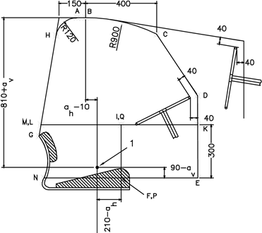 | Figure 7.1.b Rear view 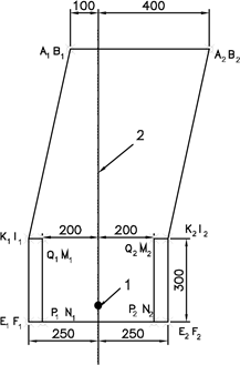 |
Figure 7.1.c
Seen from above
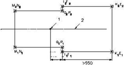
Figure 7.2.a
Clearance zone for tractors with reversible seat position: two-post rollbar
Figure 7.2.b
Clearance zone for tractors with reversible seat position: other types of ROPS
Figure 7.3
Example of crushing rig of the tractor
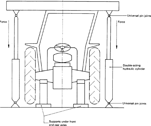
Figure 7.4
Example of apparatus for measuring elastic deflection

3
–
Total deflection (permanent plus elastic)
Figure 7.5
Force/deflection curve
Overload test not necessary

Notes:U.K.
1.Locate Fa in relation to 0,95 D’U.K.
2.Overload test not necessary as Fa ≤ 1,03 F’U.K.
Figure 7.6
Force / deflection curve
Overload test necessary
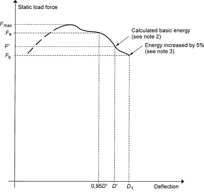
Notes:U.K.
1.Locate Fa in relation to 0,95 D’U.K.
2.Overload test necessary as Fa > 1,03 F’U.K.
3.Overload test performance satisfactory as Fb > 0,97 F’ and Fb > 0,8 Fmax.U.K.
Figure 7.7
Force/deflection curve
Overload test to be continued
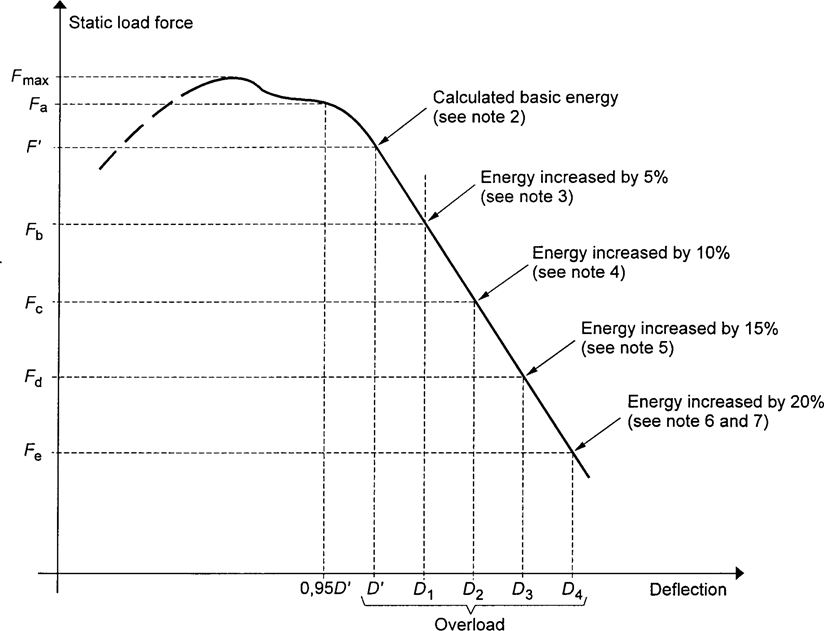
Notes:U.K.
1.Locate Fa in relation to 0,95 D’U.K.
2.Overload test necessary as Fa > 1,03 F’U.K.
3.Fb < 0,97 F’ therefore further overload necessaryU.K.
4.Fc < 0,97 Fb therefore further overload necessaryU.K.
5.Fd < 0,97 Fc therefore further overload necessaryU.K.
6.Overload test performance satisfactory, if Fe > 0,8 Fmax U.K.
7.Failure at any stage when load drops below 0,8 Fmax.U.K.
B2.ALTERNATIVE DYNAMIC TEST PROCEDUREU.K.
This section sets out the dynamic testing procedure alternative to the static test procedure set out in section B1.
4. Rules and directions U.K.
4.1. Conditions for testing the strength of protective structures and of their attachment to tractors U.K.
4.1.1.General requirementsU.K.
See requirements stated for static testing in section B1
4.1.2.TestsU.K.
4.1.2.1.Sequence of tests according to the Dynamic ProcedureU.K.
The sequence of tests, without prejudice to the additional tests mentioned in sections 4.2.1.6 and 4.2.1.7 is as follows:
(1)
impact at the rear of the structure
(see 4.2.1.1);
(2)
rear crushing test
(see 4.2.1.4);
(3)
impact at the front of the structure
(see 4.2.1.2);
(4)
impact at the side of the structure
(see 4.2.1.3);
(5)
crushing at the front of the structure
(see 4.2.1.5).
4.1.2.2.General requirementsU.K.
4.1.2.2.1.If, during the test, any part of the tractor restraining equipment breaks or moves, the test shall be restarted.U.K.
4.1.2.2.2.No repairs or adjustments of the tractor or protective structure may be carried out during the tests.U.K.
4.1.2.2.3.The tractor gear box shall be in neutral and the brakes off during the tests.U.K.
4.1.2.2.4.If the tractor is fitted with a suspension system between the tractor body and the wheels, it shall be blocked during the tests.U.K.
4.1.2.2.5.The side chosen for application of the first impact on the rear of the structure shall be that which, in the opinion of the testing authorities, will result in the application of the series of impacts or loads under the most unfavourable conditions for the structure. The lateral impact and the rear impact shall be applied on both sides of the longitudinal median plane of the protective structure. The front impact shall be applied on the same side of the longitudinal median plane of the protective structure as the lateral impact.U.K.
4.1.3.Acceptance conditionsU.K.
4.1.3.1.A protective structure is regarded as having satisfied the strength requirements if it fulfils the following conditions:U.K.
4.1.3.1.1.
after each test it shall be free from tears or cracks, as defined in 4.2.1.2.1. If significant tears or cracks appear during the test, an additional impact test or crushing test as defined in 4.2.1.6 or 4.2.1.7 must be performed immediately after the test which caused these tears or cracks to appear;
4.1.3.1.2.
during the tests other than the overload test, no part of the protective structure must enter the clearance zone as defined in 1.6;
4.1.3.1.3.
during the tests other than the overload test, all parts of the clearance zone shall be secured by the structure, in accordance with 4.2.2.2;
4.1.3.1.4.
during the tests the protective structure must not impose any constraints on the seat structure;
4.1.3.1.5.
the elastic deflection, measured in accordance with 4.2.2.3 shall be less than 250 mm.
4.1.3.2.There shall be no accessories presenting a hazard for the driver. There shall be no projecting part or accessory which is liable to injure the driver should the tractor overturn, or any accessory or part which is liable to trap him — for example by the leg or the foot — as a result of the deflections of the structure.U.K.
4.1.4.[Not applicable]U.K.
4.1.5.Apparatus and equipment for dynamic testsU.K.
4.1.5.1.Pendulum blockU.K.
4.1.5.1.1.A block acting as a pendulum must be suspended by two chains or wire ropes from pivot points not less than 6 m above the ground. Means must be provided for adjusting independently the suspended height of the block and the angle between the block and the supporting chains or wire ropes.U.K.
4.1.5.1.2.The mass of the pendulum block must be 2 000 ± 20 kg excluding the mass of the chains or wire ropes which themselves must not exceed 100 kg. The length of the sides of the impact face must be 680 ± 20 mm (see figure 7.18). The block must be filled in such a way that the position of its centre of gravity is constant and coincides with the geometrical centre of the parallelepiped.U.K.
4.1.5.1.3.The parallelepiped must be connected to the system which pulls it backwards by an instantaneous release mechanism which is so designed and located as to enable the pendulum block to be released without causing the parallelepiped to oscillate about its horizontal axis perpendicular to the pendulum’s plane of oscillation.U.K.
4.1.5.2.Pendulum supportsU.K.
The pendulum pivot points must be rigidly fixed so that their displacement in any direction does not exceed 1 per cent of the height of fall.
4.1.5.3.LashingsU.K.
4.1.5.3.1.Anchoring rails with the requisite track width and covering the necessary area for lashing the tractor in all the cases illustrated (see figures 7.19, 7.20 and 7.21) must be rigidly attached to a non-yielding base beneath the pendulum.U.K.
4.1.5.3.2.The tractor shall be lashed to the rails by means of wire rope with round strand, fibre core, construction 6 × 19 in accordance with ISO 2408:2004 and a nominal diameter of 13 mm. The metal strands must have an ultimate tensile strength of 1 770 MPa.U.K.
4.1.5.3.3.The central pivot of an articulated tractor shall be supported and lashed down as appropriate for all tests. For the lateral impact test, the pivot shall also be propped from the side opposite the impact. The front and rear wheels or tracks need not be in line if this facilitates the attachment of the wire ropes in the appropriate manner.U.K.
4.1.5.4.Wheel prop and beamU.K.
4.1.5.4.1.A softwood beam of 150 mm square shall be used as a prop for the wheels during the impact tests (see figures 7.19, 7.20 and 7.21).U.K.
4.1.5.4.2.During the lateral impact tests, a softwood beam shall be clamped to the floor to brace the rim of the wheel opposite the side of impact (see figure 7.21).U.K.
4.1.5.5.Props and lashings for articulated tractorsU.K.
4.1.5.5.1.Additional props and lashings must be used for articulated tractors. Their purpose is to ensure that the section of the tractor on which the protective structure is fitted is as rigid as that of a non-articulated tractor.U.K.
4.1.5.5.2.Additional specific details are given in section 4.2.1 for the impact and crushing tests.U.K.
4.1.5.6.Tyre pressures and deflectionsU.K.
4.1.5.6.1.The tractor tyres shall not be liquid-ballasted and shall be inflated to the pressures prescribed by the tractor manufacturer for field work.U.K.
4.1.5.6.2.The lashings shall be tensioned in each particular case such that the tyres undergo a deflection equal to 12 per cent of the tyre wall height (distance between the ground and the lowest point of the rim) before tensioning.U.K.
4.1.5.7.Crushing rigU.K.
A rig as shown in figure 7.3 shall be capable of exerting a downward force on a protective structure through a rigid beam approximately 250 mm wide connected to the load-applying mechanism by means of universal joints. Suitable axle stands shall be provided so that the tractor tyres do not bear the crushing force.
4.1.5.8.Measuring apparatusU.K.
The following measuring apparatus is needed:
4.1.5.8.1.
device for measuring the elastic deflection (the difference between the maximum momentary deflection and the permanent deflection, see figure 7.4).
4.1.5.8.2.
device for checking that the protective structure has not entered the clearance zone and that the latter has remained within the structure’s protective during the test (see section 4.2.2.2).
4.2. Dynamic test procedure U.K.
4.2.1.Impact and crushing testsU.K.
4.2.1.1.Impact at the rearU.K.
4.2.1.1.1.The tractor shall be so placed in relation to the pendulum block that the block will strike the protective structure when the impact face of the block and the supporting chains or wire ropes are at an angle with the vertical plane A equal to M/100 with a 20° maximum, unless, during deflection, the protective structure at the point of contact forms a greater angle to the vertical. In this case the impact face of the block shall be adjusted by means of an additional support so that it is parallel to the protective structure at the point of impact at the moment of maximum deflection, the supporting chains or wire ropes remaining at the angle defined above.U.K.
The suspended height of the block shall be adjusted and necessary steps taken so as to prevent the block from turning about the point of impact.
The point of impact is that part of the protective structure likely to hit the ground first in a rearward overturning accident, normally the upper edge. The position of the centre of gravity of the block is 1/6 of the width of the top of the protective structure inwards from a vertical plane parallel to the median plane of the tractor touching the outside extremity of the top of the protective structure.
If the structure is curved or protruding at this point, wedges enabling the impact to be applied thereon must be added, without thereby reinforcing the structure.
4.2.1.1.2.The tractor must be lashed to the ground by means of four wire ropes, one at each end of both axles, arranged as indicated in figure 7.19. The spacing between the front and rear lashing points must be such that the wire ropes make an angle of less than 30° with the ground. The rear lashings must in addition be so arranged that the point of convergence of the two wire ropes is located in the vertical plane in which the centre of gravity of the pendulum block travels.U.K.
The wire ropes must be tensioned so that the tyres undergo the deflections given in 4.1.5.6.2. With the wire ropes tensioned, the wedging beam shall be placed in front of and tight against the rear wheels and then fixed to the ground.
4.2.1.1.3.If the tractor is of the articulated type, the point of articulation shall, in addition, be supported by a wooden block at least 100 mm square and firmly lashed to the ground.U.K.
4.2.1.1.4.The pendulum block shall be pulled back so that the height of its centre of gravity above that at the point of impact is given by one of the following two formulae:U.K.
or
The pendulum block is then released and strikes the protective structure.
4.2.1.1.5.For tractors with a reversible driver’s position (reversible seat and steering wheel), the height shall be whichever is greater of either of the above or either of the following:U.K.
for tractor with a reference mass of less than 2 000 kg;
for tractor with a reference mass of more than 2 000 kg.
4.2.1.2.Impact at the frontU.K.
4.2.1.2.1.The tractor shall be so placed in relation to the pendulum block that the block will strike the protective structure when the impact face of the block and the supporting chains or wire ropes are at an angle with the vertical plane A equal to M/100 with a 20° maximum, unless, during deflection, the protective structure at the point of contact forms a greater angle to the vertical. In this case the impact face of the block shall be adjusted by means of an additional support so that it is parallel to the protective structure at the point of impact at the moment of maximum deflection, the supporting chains or wire ropes remaining at the angle defined above.U.K.
The suspended height of the pendulum block shall be adjusted and the necessary steps taken so as to prevent the block from turning about the point of impact.
The point of impact is that part of the protective structure likely to hit the ground first if the tractor overturned sideways while travelling forward, normally the upper edge. The position of the centre of gravity of the block is 1/6 of the width of the top of the protective structure inwards from a vertical plane parallel to the median plane of the tractor touching the outside extremity of the top of the protective structure.
If the structure is curved or protruding at this point, wedges enabling the impact to be applied thereon must be added, without thereby reinforcing the structure.
4.2.1.2.2.The tractor must be lashed to the ground by means of four wire ropes, one at each end of both axles, arranged as indicated in figure 7.20. The spacing between the front and rear lashing points must be such that the wire ropes make an angle of less than 30° with the ground. The rear lashings must in addition be so arranged that the point of convergence of the two wire ropes is located in the vertical plane in which the centre of gravity of the pendulum block travels.U.K.
The wire ropes must be tensioned so that the tyres undergo the deflections given in 4.1.5.6.2. With the wire ropes tensioned, the wedging beam shall be placed behind and tight against the rear wheels and then fixed to the ground.
4.2.1.2.3.If the tractor is of the articulated type, the point of articulation shall, in addition, be supported by a wooden block at least 100 mm square and firmly lashed to the ground.U.K.
4.2.1.2.4.The pendulum block shall be pulled back so that the height of its centre of gravity above that at the point of impact is given by one of the following two formulae, to be chosen according to the reference mass of the assembly subjected to the tests:U.K.
for tractor with a reference mass of less than 2 000 kg;
for tractor with a reference mass of more than 2 000 kg.
The pendulum block is then released and strikes the protective structure.
4.2.1.2.5.In case of tractors with a reversible driver’s position (reversible seat and steering wheel):U.K.
if the protective structure is a rear two-post rollbar, the above formula shall apply;
for other types of protective structure, the height shall be whichever is greater from the formula applied above and that selected below:
or
The pendulum block is then released and strikes the protective structure.
4.2.1.3.Impact from the sideU.K.
4.2.1.3.1.The tractor shall be so placed in relation to the pendulum block that the block will strike the protective structure when the impact face of the block and the supporting chains or wire ropes are vertical unless, during deflection, the protective structure at the point of contact forms an angle of less than 20° to the vertical. In this case the impact face of the block shall be adjusted by means of an additional support so that it is parallel to the protective structure at the point of impact at the moment of maximum deflection, the supporting chains or wire ropes remaining vertical on impact.U.K.
4.2.1.3.2.The suspended height of the pendulum block shall be adjusted and necessary steps taken so as to prevent the block from turning about the point of impact.U.K.
4.2.1.3.3.The point of impact shall be that part of the protective structure likely to hit the ground first in a sideways overturning accident, normally the upper edge. Unless it is certain that another part of this edge would hit ground first, the point of impact shall be in the plane at right angles to the median plane and passing 60 mm in front of the Seat Index Point, the seat being set at the mid position of longitudinal adjustment.U.K.
4.2.1.3.4.For tractors with a reversible driver’s position (reversible seat and steering wheel), the point of impact shall be in the plane at right angles to the median plane and passing at the midpoint of the segment joining the two Seat Index Points defined by joining the two different positions of the seat. For protective structures having a two-post system, the impact shall be located on one of the two posts.U.K.
4.2.1.3.5.The tractor wheels on the side which is to receive the impact must be lashed to the ground by means of wire ropes passing over the corresponding ends of the front and rear axles. The wire ropes must be tensioned to produce the tyre deflection values given in 4.1.5.6.2.U.K.
With the wire ropes tensioned, the wedging beam shall be placed on the ground, pushed tight against the tyres on the side opposite that which is to receive the impact and then fixed to the ground. It may be necessary to use two beams or wedges if the outer sides of the front and rear tyres are not in the same vertical plane. The prop shall then be placed as indicated in figure 7.21 against the rim of the most heavily loaded wheel opposite to the point of impact, pushed firmly against the rim and then fixed at its base. The length of the prop shall be such that it makes an angle of 30° ± 3° with the ground when in position against the rim. In addition, its thickness shall, if possible, be between 20 and 25 times less than its length and between 2 and 3 times less than its width. The props shall be shaped at both ends as shown in the details on figure 7.21.
4.2.1.3.6.If the tractor is of the articulated type, the point of articulation shall in addition be supported by a wooden block at least 100 mm square and laterally supported by a device similar to the prop pushed against the rear wheel as in 4.2.1.3.5. The point of articulation shall then be lashed firmly to the ground.U.K.
4.2.1.3.7.The pendulum block shall be pulled back so that the height of its centre of gravity above that at the point of impact is given by one of the following two formulae, to be chosen according to the reference mass of the assembly subjected to the tests:U.K.
for tractors with a reference mass of less than 2 000 kg;
for tractors with a reference mass of more than 2 000 kg.
4.2.1.3.8.In case of tractors with a reversible driver’s position (reversible seat and steering wheel):U.K.
if the protective structure is a rear two-post rollbar, the selected height shall be whichever is greater from the formulae applicable above and below:
for tractor with a reference mass of less than 2 000 kg;
for tractor with a reference mass of more than 2 000 kg.
for other types of protective structures, the selected height shall be whichever is greater from the formulae applicable above and below:
for tractor with a reference mass less than 2 000 kg;
for tractor with a reference mass of more than 2 000 kg.
The pendulum block is then released and strikes the protective structure.
4.2.1.4.Crushing at the rearU.K.
All provisions are identical to those given in point 3.2.1.4 of section B1 to this Annex.
4.2.1.5.Crushing at the frontU.K.
All provisions are identical to those given in section 3.2.1.5 of section B1 to this Annex.
[4.2.1.6. Additional impact tests U.K.
If cracks or tears which cannot be considered negligible appear during an impact test, a second, similar test, but with a height of fall of:

shall be performed immediately after the impact tests causing these tears or cracks to appear, ‘ a ’ being the ratio of the permanent deformation (Dp) to the elastic deformation (De):

as measured at the point of impact. The additional permanent deformation due to the second impact shall not exceed 30 per cent of the permanent deformation due to the first impact.
In order to be able to carry out the additional test, it is necessary to measure the elastic deformation during all the impact tests.]
4.2.1.7.Additional crushing testsU.K.
If during a crushing test, significant cracks or tears appear, a second, similar, crushing test, but with a force equal to 1,2 Fv shall be performed immediately after the crushing tests which caused these tears or cracks to appear.
4.2.2.Measurements to be madeU.K.
4.2.2.1.Fractures and cracksU.K.
After each test all structural members, joints and fastening systems shall be visually examined for fractures or cracks, any small cracks in unimportant parts being ignored.
Any tears caused by the edges of the pendulum weight are to be ignored.
4.2.2.2.Entry into the clearance zoneU.K.
During each test the protective structure shall be examined to see whether any part it has entered a clearance zone round the driving seat as defined in 1.6.
Furthermore, the clearance zone shall not be outside the protection of the protective structure. For this purpose, it shall be considered to be outside the protection of the structure if any part of it would come in contact with flat ground if the tractor overturned towards the direction from which the test load is applied. For estimating this, the front and rear tyres and track width setting shall be the smallest standard fitting specified by the manufacturer.
4.2.2.3.Elastic deflection (under side impact)U.K.
The elastic deflection shall be measured (810 + av) mm above the Seat Index Point, in the vertical plane in which the load is applied. For this measurement, any apparatus similar to that illustrated in figure 7.4 may be used.
4.2.2.4.Permanent deflectionU.K.
After the final crushing test, the permanent deflection of the protective structure shall be recorded. For this purpose, before the start of the test, the position of the main roll-over protective structure members in relation to the Seat Index Point shall be used.
4.3. Extension to other tractor models U.K.
All provisions are identical to those given in section 3.3 of section B1 to this Annex.
4.4.[Not applicable]U.K.
4.5. Cold weather performance of protective structures U.K.
All provisions are identical to those given in section 3.5 of section B1 to this Annex.
Figure 7.18
Pendulum block and its suspending chains or wire ropes
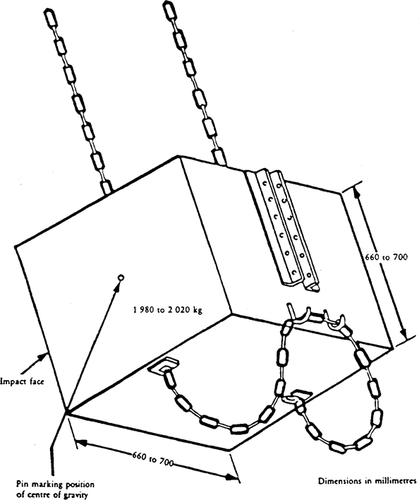
Figure 7.19
Example of tractor lashing (rear impact)
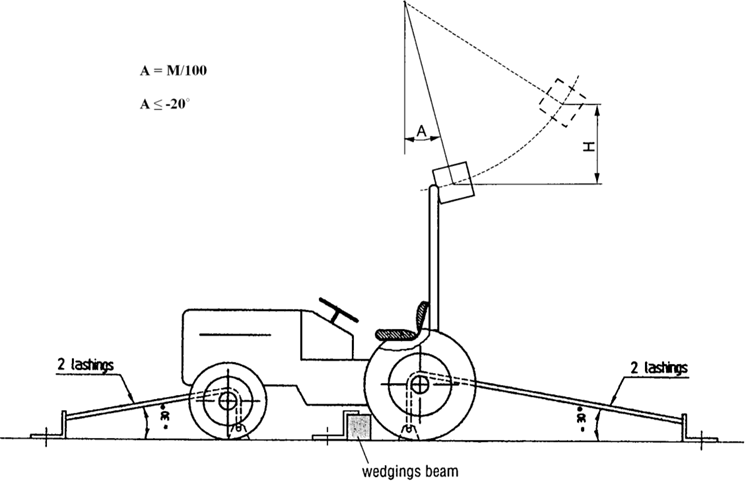
Figure 7.20
Example of tractor lashing (front impact)
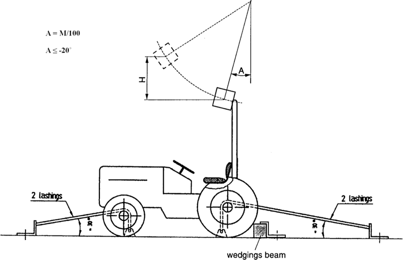
Figure 7.21
Example of tractor lashing (side impact)
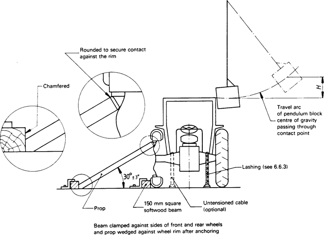
[B3 PERFORMANCE REQUIREMENTS FOR FOLDABLE ROLL-OVER PROTECTION STRUCTURES U.K.
5.1. Scope U.K.
This Section provides minimum performance and tests requirements for rear mounted foldable ROPS which are raised and/or lowered manually by a standing operator (with or without partial assistance) and locked manually or automatically.
5.2. For the purposes of this section, the following definitions shall apply: U.K.
5.2.1.
‘ hand-operated foldable ROPS ’ is a rear-mounted dual pillar protective structure with hand raising/lowering directly managed by the operator (with or without partial assistance);
5.2.2.
‘ automatic foldable ROPS ’ is a rear-mounted dual pillar protective structure with full assisted raising/lowering operations;
5.2.3.
‘ locking system ’ is a device fitted to lock, by hand or automatically, the ROPS in the raised or lowered positions;
5.2.4.
‘ grasping area ’ is an area defined by the manufacturer as a portion of the ROPS and/or additional handle fitted to the ROPS where the operator is allowed to carry out the raising/lowering operations;
5.2.5.
‘ accessible part of the grasping area ’ is the area where the ROPS is handled by the operator during the raising/lowering operations; this area shall be defined with regard to the geometric centre of cross sections of the grasping area;
5.2.6.
‘ accessible zone ’ is the volume where a standing operator can apply a force in order to raise/lower the ROPS;
5.2.7.
‘ pinching point ’ is a point where parts move in relation to each other or to fixed parts in such a way as may cause persons or certain parts of their bodies to be pinched;
5.2.8.
‘ shear point ’ is a point where parts move along each other or along other parts in such a way as may cause persons or certain parts of their bodies to be pinched or shorn;
5.2.9.
‘ place to stand ’ is a place on the tractor platform accessible from the driving position main access with sufficient space for a standing operator.
5.3. Hand-operated foldable ROPS U.K.
5.3.1. Prior conditions for the test U.K.
5.3.1.1. Grasping area U.K.
The manual handling shall be done by a standing operator with one or more grasps on grasping area of the roll-bar.
The roll-bar can be handled from the ground or from a place to stand on the platform (Figures 7.8a and 7.8b).
The operator can handle the roll-bar in parallel with or in front of its trajectory.
A multiple step process with multiple operator positions and multiple defined grasping areas is allowed.
The grasping area shall be clearly and permanently identified (Figure 7.9).
This area has to be designed without sharp edges, sharp angles and rough surfaces likely to cause injury to the operator.
This area could be on one or both sides of the tractor and could be a structural part of the roll-bar or additional handles. In this grasping area the manual handling to raise or lower the roll-bar shall not create shearing, pinching or uncontrollable movement hazards to the operator.
5.3.1.2. Accessible zones U.K.
Three accessible zones with different amount of allowed force are defined with respect to horizontal plane of the ground and the vertical planes tangent to the outer parts of the tractor that limit the position or the displacement of the operator (Figure 7.10).
Zone I: comfort zone
Zone II: accessible zone without forward leaning of the body
Zone III: accessible zone with forward leaning of the body
Handling of the roll-bar in parallel with its trajectory
The position and the movement of the operator are limited by obstacles. These are parts of the tractor and are defined by vertical planes tangent to the external edges of the obstacle.
If the operator needs to move the feet during the manual handling of the roll-bar a displacement is allowed either within a parallel plane to the roll-bar trajectory or within just one more parallel plane to the previous one so as to overcome an obstacle. The overall displacement shall be considered as a combination of straight lines parallel and perpendicular to the roll-bar trajectory. A perpendicular displacement is accepted provided that the operator comes closer to the roll-bar. The accessible area shall be considered as the envelope of the different accessible zones (Figure 7.11).
Handling of the roll-bar in front of its trajectory:
Only for handling of the roll-bar in front of its trajectory are considered as accessible extensions of the zone II and zone III (Figure 7.12). In these extensions the acceptable actuation forces are the same ones as respectively in zone II and in the zone III.
If the operator needs to move during the manual handling of the roll-bar it must be done so by a displacement without any obstacle within a plane parallel to the roll-bar trajectory.
In this case the accessible area shall be considered as the envelope of the different accessible zones.
5.3.1.3. Place to stand U.K.
Any place to stand on the platform declared by the manufacturer shall be accessible from the main access to the driving position and fulfil the following requirements:
A place provided for standing shall have sufficient space for both of the operator's feet, be flat and have a slip-resistant surface. Depending on the machine configuration, it may consist of two separate surfaces and may use machine components. It shall be positioned so that the operator can maintain stability while carrying out the service required and be on the same height level with a tolerance of ± 50 mm.
Handhold(s) and/or railings shall be provided in order to allow three-point contact. Parts of the machine can be considered to fulfil this requirement.
It is considered that a place for standing has sufficient space if its surface is at least a square in cross section of 400 mm per side (Figure 7.13).
Alternatively the place to stand requirement may be met by providing sufficient space for one foot on a flat surface and one knee on the seat.
5.3.1.4. Test conditions U.K.
The tractor must be fitted with tyres having the greatest diameter indicated by the manufacturer and the smallest cross-section for tyres of that diameter. The tyres must be inflated to the pressure recommended for field work.
The rear wheels must be set to the narrowest track width; the front wheels must be set as closely as possible to the same track width. If it is possible to have two front track settings which differ equally from the narrowest rear track setting, the wider of these two front track settings must be selected.
5.3.2. Test procedure U.K.
The aim of the test is to measure the force necessary to raise or lower the roll-bar. The test will be carried out in static condition: no initial movement of the roll-bar. Each measurement of the force necessary to raise or lower the roll-bar shall be made in a direction tangent to the trajectory of the roll-bar and passing through the geometric centre of cross sections of the grasping area.
The grasping area is considered accessible when located within the accessible zones or the envelope of different accessible zones (Figure 7.14).
The force necessary to raise and lower the roll-bar shall be measured in different points that are within the accessible part of the grasping area (Figure 7.15).
The first measure is carried out at the extremity of the accessible part of the grasping area when the roll-bar is fully lowered (Point 1 in Figure 7.15).
The second measure is defined according to the position of Point 1 after rotation of the roll-bar up to the point where the perpendicular to the trajectory of the roll-bar is vertical (Point 2 in Figure 7.15).
The third measure is carried out after rotation of the roll-bar up to the top of the accessible part of the grasping area (Point 3 in Figure 7.15).
If in this third measure the roll-bar is not fully raised, a point shall be measured at the extremity of the accessible part of the grasping area when the roll bar is fully raised (Point 4 in Figure 7.15).
If between point 1 and point 3 the trajectory of extremity of the accessible part of the grasping area crosses the limit between Zone I and Zone II an additional measurement shall be made at this point (Figure 7.16).
The maximum forces in these points shall not exceed the acceptable force of the zone (I, II or III).
In order to measure the force in the required points, it is possible either to measure directly the value or to measure the torque needed to raise or lower the roll-bar so as to calculate the force.
5.3.3. Condition of acceptance U.K.
5.3.3.1. Force requirement U.K.
The force acceptable for the actuation of the ROPS depends on the accessible zone as shown in Table 7.2.
Table 7.2
Allowed forces
| Zone | I | II | III |
|---|
| Acceptable force (N) | 100 | 75 | 50 |
|---|
An increase of no more than 25 % of these acceptable forces is allowed when the roll-bar is fully lowered and fully raised.
An increase of no more than 25 % of these acceptable forces is allowed if the roll-bar is handled in front of its trajectory.
An increase of no more than 50 % of these acceptable forces is allowed in the lowering operation.
5.3.3.2. Additional requirements U.K.
The manual handling to raise or lower the roll-bar shall not create shearing, pinching or uncontrollable movement hazards to the operator.
A pinching point is not considered dangerous for the operator hands part if in the grasping area the safety distances between the roll-bar and fixed parts of the tractor are no less than 100 mm for hand, wrist, fist and 25 mm for finger (ISO 13854:1996). The safety distances shall be checked with respect to the mode of handling foreseen by the manufacturer in the operator's manual.
5.4. Hand locking system U.K.
The device fitted to lock the ROPS in the upright/lowered position must be designed:
to be handled by one standing operator and located in one of the accessible zones;
to be hardly separated from the ROPS (for example captive pins as locking pins or retaining pins);
to avoid any confusion in the locking operation (the proper location of the pins shall be indicated);
to avoid unintentional removing or losing of parts.
If the devices employed to lock the ROPS in the upright/lowered position are pins they shall be inserted or removed freely. If to do so there is a need to apply a force on the roll-bar this shall comply with the requirements of points 1 and 3 or 4 (see point 5.3).
For all other locking devices, they shall be engineered according to an ergonomic approach for what concerns the shape and the force especially avoiding pinching or shearing hazards.
5.5. Preliminary test of automatic locking system U.K.
An automatic locking system fitted on hand-operated foldable ROPS has to be submitted to a preliminary test before the ROPS strength test.
The roll-bar shall be moved from the lower position to the upright locked position and back. These operations correspond to one cycle. 500 cycles shall be completed.
This could be done manually or with the use of external energy (hydraulic, pneumatic or electric actuators). In both cases the force shall be applied within a plane parallel to the trajectory of the roll-bar and passing through the grasping area, the angular speed of the roll-bar shall be roughly constant and less than 20 deg/s.
After the 500 cycles, the force applied when the roll-bar is in the upright position shall not exceed by more than 50 % the allowed force (Table 7.2).
The unlocking of the roll-bar shall be done following the operator manual.
After the completion of the 500 cycles there shall be no maintenance or adjustment on the locking system.
Note 1: The preliminary test could be applied to automatic foldable ROPS systems as well. The test should be carried out before the ROPS strength test. U.K.
Note 2: The preliminary test could be carried out by the manufacturer. In such a case the manufacturer shall provide the test station with a certificate stating that the test has been done according the test procedure and that there was no maintenance or adjustment on the locking system after the completion of the 500 cycles. The test station will check the performance of the device with one cycle from the lower position to the upright locked position and back.] U.K.


Explanatory notes to Annex X U.K.
[(1) Unless the numbering of sections B2 and B3 which has been harmonised with the whole Annex, the text of the requirements and the numbering set out in point B are identical with the text and numbering of the OECD standard Code for the official testing of rear mounted roll-over protective structures on narrow-track wheeled agricultural and forestry tractors, OECD standard Code 7, Edition 2017 of February 2017.] U.K.
(2) Users are reminded that the seat index point is determined according to ISO 5353:1995 and is a fixed point with respect to the tractor that does not move as the seat is adjusted away from the mid-position. For purposes of determining the clearance zone, the seat shall be placed in the rear and uppermost position.U.K.
(3) Permanent + elastic deflection measured at the point when the required energy level is obtained.U.K.