- Latest available (Revised)
- Original (As adopted by EU)
Commission Delegated Regulation (EU) No 3/2014Show full title
Commission Delegated Regulation (EU) No 3/2014 of 24 October 2013 supplementing Regulation (EU) No 168/2013 of the European Parliament and of the Council with regard to vehicle functional safety requirements for the approval of two- or three-wheel vehicles and quadricycles (Text with EEA relevance)
You are here:

What Version
More Resources
Revised version PDFs
- Revised 16/10/20166.74 MB
Legislation originating from the EU
When the UK left the EU, legislation.gov.uk published EU legislation that had been published by the EU up to IP completion day (31 December 2020 11.00 p.m.). On legislation.gov.uk, these items of legislation are kept up-to-date with any amendments made by the UK since then.


This item of legislation originated from the EU
Legislation.gov.uk publishes the UK version. EUR-Lex publishes the EU version. The EU Exit Web Archive holds a snapshot of EUR-Lex’s version from IP completion day (31 December 2020 11.00 p.m.).
Status:
This is the original version as it was originally adopted in the EU.
This legislation may since have been updated - see the latest available (revised) version
ANNEX VIII Requirements applying to driver-operated controls including identification of controls, tell-tales and indicators
1.Requirements for the approval of a type of vehicle with regard to identification of controls, tell-tales and indicators
1.1.Identification of controls, tell-tales and indicators
1.1.1.Vehicles of categories L1e-B and L3e shall meet all the relevant requirements of UNECE regulation No 60 except those in Annex 3 to that regulation. The requirements of points 1.1.1.1 and 1.1.1.2 shall also be taken into account.
1.1.1.1.It shall be ensured that no deviations in the shape and orientation of the provided symbols are permitted.
1.1.1.2.It shall further be ensured that the corresponding requirements of points 2 to 2.2.1.6 are met with respect to functions for which no symbol is provided in UNECE regulation No 60, but for which symbols are provided in this Regulation.
1.1.2.Vehicles of category L4e shall meet all the relevant requirements in points 1.1.1 to 1.1.1.2 for vehicle category L3e.
1.1.3.Vehicles of categories L2e, L5e, L6e and L7e shall meet the requirements of point 2 to 2.2.1.6 or, alternatively, the relevant requirements of UNECE regulation No 121(1), as prescribed for vehicle category M1.
1.2.Speedometer and odometer
1.2.1.Vehicles with a maximum design vehicle speed exceeding 25 km/h shall be fitted with a speedometer as well as an odometer.
1.2.1.1.Vehicles of categories L1e, L2e, L3e, L4e and L5e fitted with a speedometer shall meet all the relevant requirements of UNECE regulation No 39.
1.2.1.2.Vehicles of category L6e fitted with a speedometer shall, in the absence of specific requirements for vehicles of that category, meet all the relevant requirements of UNECE regulation No 39, as prescribed for vehicle category L2e.
1.2.1.3.Vehicles of category L7e fitted with a speedometer shall, in the absence of specific requirements for vehicles of that category, meet all the relevant requirements of UNECE regulation No 39, as prescribed for vehicle category L5e.
1.2.2.Explanatory notes to UNECE regulation No 39
1.2.2.1.The technical service may accept an increased temperature range of 296 ± 15 K (23 ± 15 °C) instead of the range stated in point 5.2.3 of UNECE regulation No 39 if it can be demonstrated that the speedometer equipment is not sensitive to such temperature variations (e.g. with digital displays).
2.Specific requirements
2.1.Controls, tell-tales and indicators fitted to the vehicle and listed in point 2.1.10 shall comply with the requirements regarding location, identification, colour and illumination. For functions for which no symbol is provided in this Regulation, the manufacturer may use a symbol following the appropriate ISO 6727:2012 or 2575:2010/Amd1:2011 standards. Where no ISO symbol is available, the manufacturer may use a symbol of its own conception. In any case, such symbol shall not cause confusion with any prescribed symbol.
2.1.1.The symbols shall stand out clearly against the background.
2.1.1.1.Contrasting colours shall be used to comply with the requirements of point 2.1.1.
2.1.2.The symbols shall be placed on the control or control tell-tale to be identified, or in immediate proximity thereof. Where this is not possible, the symbol and control or tell-tale shall be joined by a continuous dash that is as short as possible.
2.1.3.Deviations in the shape of the provided symbols are not permitted.
2.1.4.If necessary for clarity, supplementary symbols may be used in conjunction with any symbol as specified, provided that they do not cause confusion with any symbol specified in this Regulation.
2.1.5.At the manufacturer’s discretion, any control or indicator as well as their identifications may be capable of being illuminated at any time.
2.1.6.A tell-tale shall not emit light except when identifying the malfunction or vehicle condition it is designed to indicate or during a functional check (e.g. bulb check).
2.1.7.Means shall be provided to ensure that tell-tales and their identification are visible and recognisable under all driving conditions.
2.1.7.1.When illuminated, tell-tales and their associated identifying symbols shall be perfectly visible and recognisable under all ambient lighting conditions.
2.1.8.When used for optical tell-tales, the following colours shall have the meanings indicated:
red: danger to persons or very serious damage to equipment is immediate or imminent,
yellow: outside normal operating limits, vehicle system malfunction, damage to vehicle likely, or other condition which may produce hazard in the longer term (caution),
green: safety, normal operating condition (except if blue or yellow is required).
The mandatory colours are given in point 2.1.10. It shall be verified that no inappropriate colour is used for tell-tales even if fitted cumulatively (e.g. red for normal cruise control operation or for ‘sport’ mode).
2.1.9.If colour coding is used to identify the limits of the adjustment range of a temperature function (e.g. passenger compartment heating system), the hot limit shall be identified by the colour red and the cold limit by the colour blue. If the status or limit of a function is shown by an indicator separated from and not adjacent to the control for that function, both the control and the indicator shall be independently identified with the appropriate symbol.
2.1.10.Designation and identification of symbols:
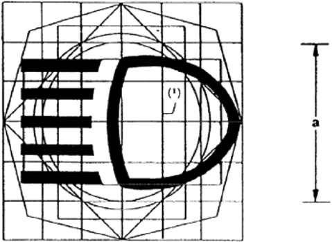
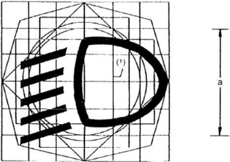
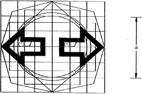
Figure 8-4
Hazard warning signal (control / tell-tale)
Two possibilities:
Identifying signal (Figure 8-4),
Tell-tale colour: red
or
Simultaneous operation of the separate direction indicator tell-tales (Figure 8-3), provided that these normally operate independently (see Note below Figure 8-3).
Explanatory notes:
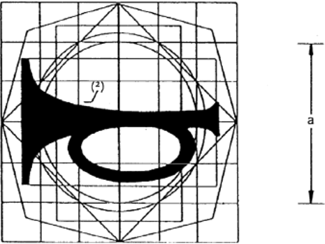
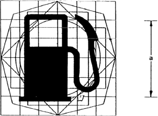
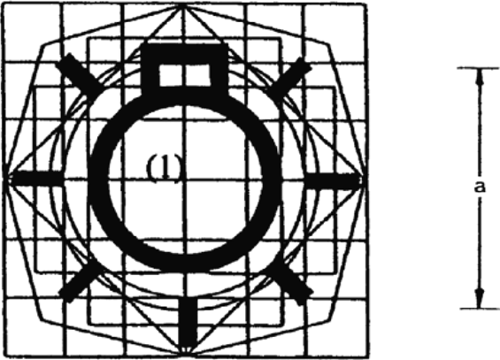
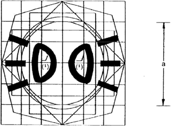
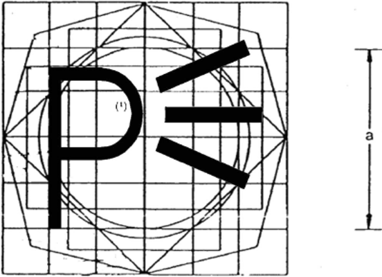
(1)The framed areas may be solid.
(2)The dark part of this symbol may be replaced by its silhouette.
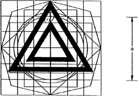
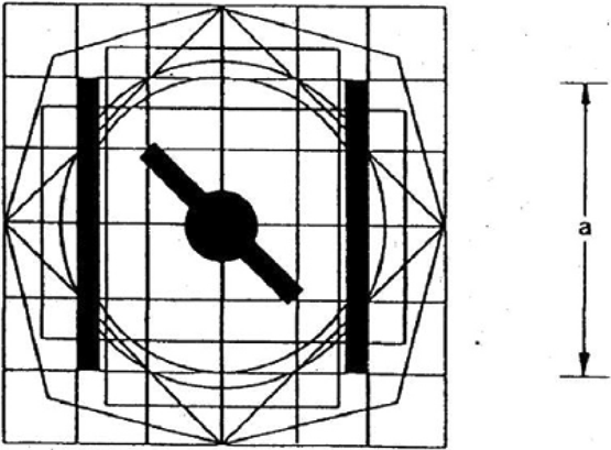
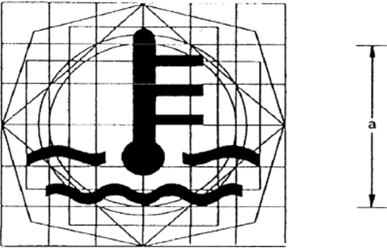
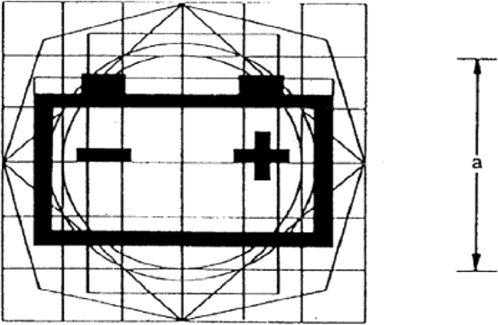
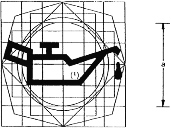
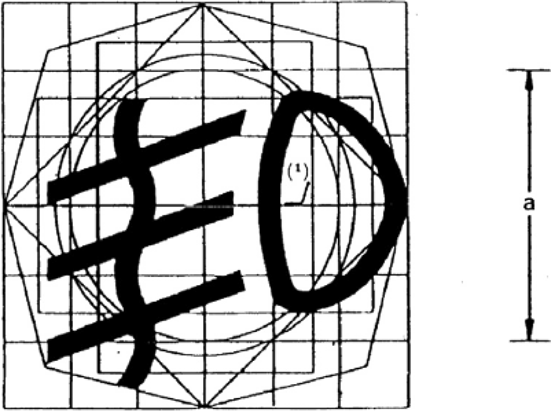
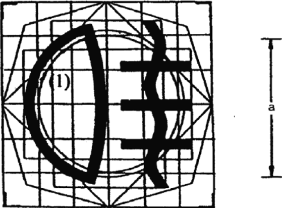
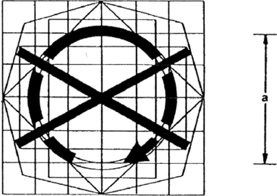
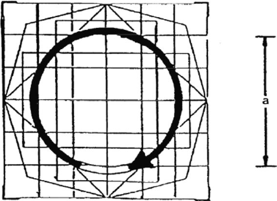
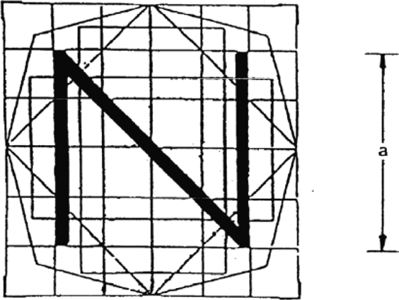
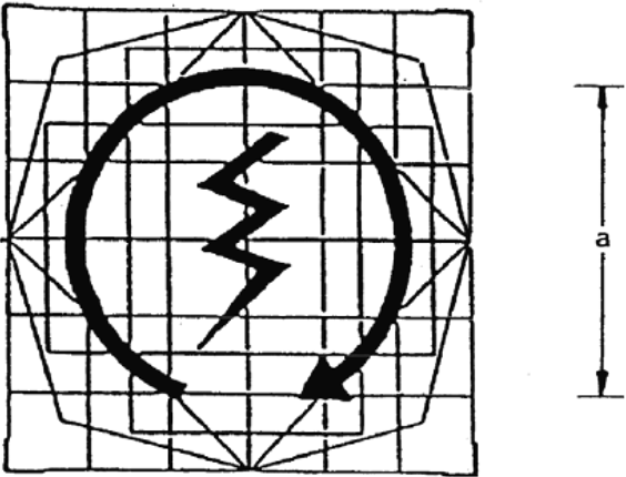
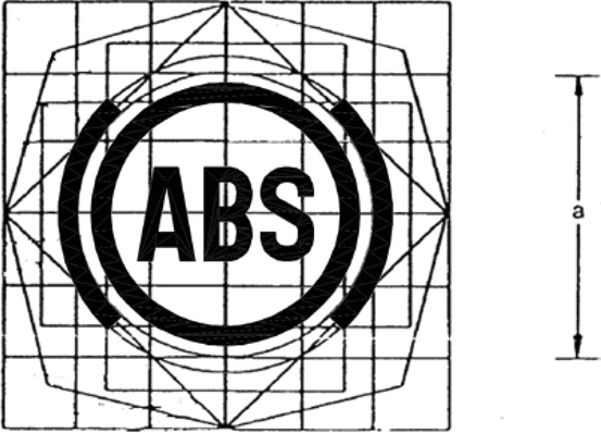
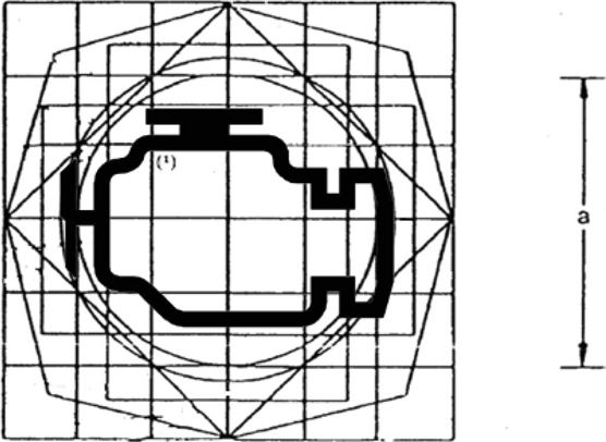
2.1.11.The model base provided in Figure 8-22 shall be used.
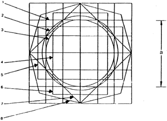
The model base consists of:
(1)
a base 50 mm square, this dimension being equal to nominal dimension ‘a’ in the original;
(2)
a base circle 56 mm in diameter having approximately the same area as the base square (1);
(3)
a second 50 mm-diameter circle is drawn within the base square (1);
(4)
a second square the tips of which lie on the base circle (2) and the sides of which are parallel to those of the base square (1);
(5)
and (6) two rectangles having the same area as the base square (1), their sides being at right angles to each other and each of them devised so as to divide the opposite sides of the base square into symmetrical points;
(7)
a third square the sides of which pass through the points of intersection of the base square (1) and the base circle (2) and are inclined at 45°, thus providing the greatest horizontal and vertical dimensions of the model base;
(8)
an irregular octagon formed by lines inclined at 30° to the sides of the square (7).
The base model is laid upon a grid the lower side of which measures 12,5 mm and coincides with the base square (1).
2.2.Common space for displaying multiple information.
2.2.1.A common space may be used to show information from any source, provided that the following requirements are met:
2.2.1.1.The tell-tales and indicators displayed in the common space shall meet the requirements of points 2.1 to 2.1.11 and shall light up at the initiation of the condition they are designed to identify.
2.2.1.2.The tell-tales and indicators listed in point 2.1.10 and shown in the common space shall light up at the initiation of any underlying condition.
2.2.1.3.Except as provided in points 2.2.1.4 to 2.2.1.6, when the condition exists for actuation of two or more tell-tales, the information shall be either:
repeated automatically in sequence,
or
indicated by visible means and capable of being selected for viewing by the driver when seated in the driving position.
2.2.1.4.The tell-tales for any braking system malfunction, headlamp driving beam and direction indicator shall not be shown in the same common space.
2.2.1.5.If any of those tell-tales are displayed in a common space with other tell-tales, their activation shall take precedence over that of anything else in the common space.
2.2.1.6.It shall not be possible to deactivate the braking system malfunction, headlamp driving beam and direction indicator tell-tales, or any other red tell-tale, when the condition for their activation still exists. It may be possible for other information displayed in a common space to be cancelled automatically or by the driver.
Options/Help
Print Options
PrintThe Whole Regulation
PrintThe Whole Annex
You have chosen to open the Whole Regulation
The Whole Regulation you have selected contains over 200 provisions and might take some time to download. You may also experience some issues with your browser, such as an alert box that a script is taking a long time to run.
Would you like to continue?
You have chosen to open Schedules only
The Schedules you have selected contains over 200 provisions and might take some time to download. You may also experience some issues with your browser, such as an alert box that a script is taking a long time to run.
Would you like to continue?
Legislation is available in different versions:
Latest Available (revised):The latest available updated version of the legislation incorporating changes made by subsequent legislation and applied by our editorial team. Changes we have not yet applied to the text, can be found in the ‘Changes to Legislation’ area.
Original (As adopted by EU): The original version of the legislation as it stood when it was first adopted in the EU. No changes have been applied to the text.
Opening Options
Different options to open legislation in order to view more content on screen at once
More Resources
Access essential accompanying documents and information for this legislation item from this tab. Dependent on the legislation item being viewed this may include:
- the original print PDF of the as adopted version that was used for the EU Official Journal
- lists of changes made by and/or affecting this legislation item
- all formats of all associated documents
- correction slips
- links to related legislation and further information resources
More Resources
Use this menu to access essential accompanying documents and information for this legislation item. Dependent on the legislation item being viewed this may include:
- the original print PDF of the as adopted version that was used for the print copy
- correction slips
Click 'View More' or select 'More Resources' tab for additional information including:
- lists of changes made by and/or affecting this legislation item
- confers power and blanket amendment details
- all formats of all associated documents
- links to related legislation and further information resources
 All content is available under the Open Government Licence v3.0 except where otherwise stated. This site additionally contains content derived from EUR-Lex, reused under the terms of the Commission Decision 2011/833/EU on the reuse of documents from the EU institutions. For more information see the EUR-Lex public statement on re-use.