- Latest available (Revised)
- Original (As adopted by EU)
Commission Delegated Regulation (EU) No 44/2014Show full title
Commission Delegated Regulation (EU) No 44/2014 of 21 November 2013 supplementing Regulation (EU) No 168/2013 of the European Parliament and of the Council with regard to the vehicle construction and general requirements for the approval of two- or three-wheel vehicles and quadricycles (Text with EEA relevance)
You are here:

What Version
More Resources
Revised version PDFs
- Revised 20/03/20182.33 MB
- Revised 16/10/20162.32 MB
Legislation originating from the EU
When the UK left the EU, legislation.gov.uk published EU legislation that had been published by the EU up to IP completion day (31 December 2020 11.00 p.m.). On legislation.gov.uk, these items of legislation are kept up-to-date with any amendments made by the UK since then.


This item of legislation originated from the EU
Legislation.gov.uk publishes the UK version. EUR-Lex publishes the EU version. The EU Exit Web Archive holds a snapshot of EUR-Lex’s version from IP completion day (31 December 2020 11.00 p.m.).
Status:
This is the original version as it was originally adopted in the EU.
This legislation may since have been updated - see the latest available (revised) version
ANNEX IX Requirements applying to fuel storage
1. General requirements
1.1.‘Type of vehicle with regard to fuel storage’ means a category of vehicles which do not differ in such essential respects as shape, size and material characteristics, and the method of mounting and location of the fuel tank on the vehicle;
1.2.Fuel tanks of vehicles fitted with one or more of these shall meet the following general requirements:
1.2.1.
Fuel tanks shall be made with materials of which the thermal, mechanical and chemical behaviour continues to be appropriate under their intended conditions of use.
1.2.2.
Fuel tanks and adjacent vehicle parts shall be designed in such a way as not to generate any electrostatic charge which could result in sparking between the tank and the chassis of the vehicle which could ignite a mixture of air and fuel.
1.2.3.
Fuel tanks shall be made so as to be corrosion-resistant.
1.2.4.
Fuel tanks shall be fitted with appropriate devices (e.g. orifices or safety valves) which automatically release any excess pressure or any pressure exceeding the service pressure. Such devices shall be so designed as to preclude any risk of ignition of a mixture of air and fuel.
1.2.5.
Fuel tanks shall be so designed that any fuel that may leak when they are being filled cannot fall on the vehicle’s exhaust system, engine or other drivetrain parts or on the inside of any passenger or luggage compartment, but is channelled to the ground.
1.2.6.
Fuel shall be unable to flow from the filler cap or any devices fitted in order to release excess pressure, even if the tank is fully inverted. Dripping is tolerated to a maximum of 30 g/min, to be verified by means of the test described in points 2.1 to 2.1.4. If the leakage rate does not appear to be constant in nature, it shall be ensured that maximum leakage rate is determined within a one minute timeframe (i.e. not averaged over a longer timeframe).
1.2.7.
No tank shall be situated in, or form, a surface (e.g. floor, wall, roof or bulkhead) of the passenger compartment or other compartment integral with it, if the vehicle is fitted with bodywork.
1.2.7.1.
For the purpose of this Annex, a vehicle is deemed to have a passenger or other compartment integral with it if it is fitted with safety glazing, side doors, a rear door, side pillars and/or a roof creating an enclosed or partly enclosed compartment. The technical service shall clearly justify the judgment criteria in the test report.
1.2.8.
The fuel filler port shall not be situated in the passenger compartment, luggage compartment or engine compartment, if any.
1.2.8.1.
Further to point 1.2.7.1 above, a vehicle is deemed to have an engine compartment or a luggage compartment if it is fitted with side panels in combination with a bonnet/hood lid and/or a boot/trunk lid creating an enclosed or partly enclosed compartment. The technical service shall clearly justify the judgment criteria in the test report.
1.2.9.
Fuel tanks shall pass the leak-tightness tests carried out with an internal pressure equal to twice the relative service pressure (design pressure) or an overpressure of 30 kPa, whichever is higher, as described in points 2.2 to 2.2.1. Any orifices may be blocked for the purpose of this test. The fuel tank shall not crack or leak during the test, but may remain permanently deformed.
1.2.9.1.
Fuel tanks made of materials other than metal are considered as meeting this requirement if they have passed the test described in points 3.4 to 3.4.1.
1.2.10.
Fuel tanks made of materials other than metal shall be subject to the tests in accordance with points 3 to 3.7.5.1 in addition to those described in points 2.1 to 2.1.4.
1.3.Vehicles fitted with one or more fuel tanks shall meet the following general requirements:
1.3.1.
Fuel tanks shall be fitted and installed in such a way as to fulfil their function in all foreseeable operating conditions.
1.3.2.
All parts and components of the vehicle’s fuel supply system shall be adequately protected by parts of the frame or bodywork against contact with possible obstacles on the ground. Such protection shall not be required if the relevant parts or components located beneath the vehicle are further from the ground than the parts of the frame or bodywork which are located immediately ahead of them.
1.3.3.
All parts and components of the vehicle’s fuel supply system shall be designed, manufactured and installed in such a way as to withstand the effects of any internal and external corrosion to which it is exposed. No motion due to torsion, flexing and vibration of the vehicle structure, engine and transmission shall subject any part or component of the fuel supply system to abnormal friction or stress.
1.3.4.
Vehicles using liquefied petroleum gas (LPG) in their propulsion system, and the LPG tanks, shall meet all relevant fitting and equipment requirements of UNECE regulation No 67(1) as prescribed for vehicle category M1.
1.3.5.
Vehicles using compressed natural gas (CNG) in their propulsion system, and the CNG tanks, shall meet all relevant fitting and equipment requirements of UNECE regulation No 110(2) as prescribed for vehicle category M1.
2. Fuel tank tests
2.1.Overturn test
2.1.1.The tank and all its accessories shall be mounted onto a test fixture in a manner corresponding to the mode of installation on the vehicle for which the tank is intended. This also applies to systems for the compensation of the interior excess pressure.
2.1.2.The test fixture shall rotate about an axis lying parallel to the longitudinal vehicle axis.
2.1.3.The test shall be carried out with the tank filled to 30 % of its total rated capacity and also 90 % of its total rated capacity with a non-flammable liquid having a density and a viscosity close to those of the fuel normally used, or with water.
2.1.4.The tank shall be turned from its installed position 90° to the left. The tank shall remain in this position for at least five minutes. The tank shall then be turned 90° further in the same direction. The tank shall be held in this position, in which it is completely inverted, for at least another five minutes. The tank shall be rotated back to its normal position.
Testing liquid that has not flowed back from the venting system into the tank may be drained and replenished if necessary.
The tank shall be turned from its installed position 90° to the right. The tank shall remain in this position for at least five minutes. The tank shall then be turned 90° further in the same direction. The tank shall be held in this position, in which it is completely inverted, for at least another five minutes. The tank shall be rotated back to its normal position.
The 90° rotations shall take place at one to three minute intervals.
2.2.Hydraulic test
2.2.1.The tank shall be subjected to a hydraulic internal pressure test which shall be carried out on an isolated unit complete with all its accessories. The tank shall be completely filled with a non-flammable liquid having a density and a viscosity close to those of the fuel normally used, or with water. After all communication with the outside has been cut off, the pressure shall be gradually increased, through the pipe connection through which fuel is fed to the engine, to the internal pressure specified in point 1.1.9 and this pressure shall be maintained for at least 60 seconds.
3. Specific requirements and tests for fuel tanks made of materials other than metal
3.1.Fuel tanks made of materials other than metal are subjected to the following additional tests:
permeability test,
shock test,
mechanical strength test,
fuel resistance test,
high-temperature test,
fire-resistance test.
3.2.Permeability test to be carried out on completely new fuel tank
3.2.1.The permeability test as part of type IV testing referred to in Annex V(A) to Regulation (EU) No 168/2013 without having to take into account any diffusion measurements for the purpose of the test in accordance with this Annex, shall be carried out on a sufficient number of tanks for the purpose of testing in accordance with points 3.3 to 3.7.5.1.
3.3.Shock test to be carried out on a fuel tank which has undergone the permeability test
3.3.1.The fuel tank is filled up to its total rated capacity with a mixture of 50 % water and 50 % ethylene glycol or with any other coolant which does not deteriorate the fuel tank material, the cryoscopic point of which is lower than  .
.
The temperature of the substances contained in the fuel tank during the test shall be 
A pendulum is used for the test. Its impact head shall have the form of an equilateral triangular pyramid with a radius of curvature of 3,0 mm at its peak and edges. The freely moving mass of the pendulum shall have a mass of 15 kg ± 0,5 kg and the exerted pendulum’s energy shall not be less than 30,0 J for each impact on the fuel tank.
The technical service may select any number of points on the fuel tank to be tested and these points shall reflect locations which are considered at risk as a result of the fitting of the tank and its position on the vehicle. Non-metal shielding shall be disregarded and frame tubing or chassis sections may be taken into account for the assessment of risk.
More than one fuel tank may be used for the completion of all impacts, provided that all fuel tanks to be used have undergone the permeability test.
There shall be no leakage of liquid following a single impact at any one of the tested points.
3.4.Mechanical strength test to be carried out on a fuel tank which has undergone the permeability test
3.4.1.The fuel tank shall be filled up to its total rated capacity, the test liquid used being water at  . The tank shall then be subjected to an internal pressure equal to twice the relative service pressure (design pressure) or an overpressure of 30 kPa, whichever is higher. The tank shall remain closed and pressurised for a period of not less than five hours at an ambient temperature of
  .
.
The fuel tank shall not show signs of leakage and any temporary or permanent deformation which may arise shall not render it unusable. Account shall be taken of specific fitting conditions if the deformation of the tank is to be assessed.
3.5.Fuel resistance test to be carried out on samples of a completely new fuel tank and samples of a fuel tank which has undergone the permeability test
3.5.1.Six tensile test-pieces of approximately the same thickness are taken from flat or nearly flat faces of the completely new fuel tank. Their tensile strength and elastic limits are established at  at an elongation rate of 50 mm/min. The obtained values shall then be compared with the tensile strength and elasticity values obtained from similar tests carried out using a fuel tank which has undergone the permeability test. The material shall be considered to be acceptable if the tensile strength differs by no more than 25 %.
3.6.High temperature test to be carried out on samples of a fuel tank which has undergone the permeability test
3.6.1.The fuel tank shall be fitted to a representative part of the vehicle and filled to 50 % of its total rated capacity with water at  . The test setup including the fuel tank shall then be placed in an ambient temperature of
  for 60 minutes, after which the fuel tank shall not display any permanent deformation or leaks and shall be in fully usable condition.
3.7.Fire resistance test to be carried out on samples of a fuel tank which has undergone the permeability test
3.7.1.Preparation of test samples
3.7.1.1.At least ten flat or nearly flat test samples 125 ± 5 mm long and 12,5 ± 0,2 mm wide shall be taken from one or more fuel tanks which have undergone the permeability test. However, if obtaining such test samples is prevented by the design characteristics (i.e. shape) of the fuel tank, it is deemed acceptable for the purpose of this test to prepare one or more special tanks with similar characteristics but with more flat or nearly flat surfaces incorporated in the walls. The overall thickness of all samples shall be within ± 5 % of the thickest sample.
3.7.1.2.Two lines shall be cut into each sample, one at 25 mm and the other at 100 mm from one end.
3.7.1.3.The edges of the test samples shall be sharply defined. Edges obtained by sawing shall be fine-sanded down in order to obtain a smooth finish.
3.7.2.Test equipment
3.7.2.1.The test chamber shall consist of a totally enclosed laboratory fume hood with a heat-resistant test-observation window. A mirror may be used in certain test enclosures in order to provide a rear view of the sample.
The fume extractor fan shall be shut down during the test and should be restarted immediately after the test in order to extract combustion products.
The test may also be carried out inside a metal box placed beneath the fume hood with the extractor fan operating.
The top and bottom walls of the box shall incorporate ventilation holes enabling sufficient air for the combustion to pass through while not subjecting the burning sample to a draught.
3.7.2.2.The supporting base shall consist of two grips which can be set in any position by means of swivel joints.
3.7.2.3.The burner shall be a gas-fired ‘Bunsen’ or ‘Tirill’ type with a 10 mm nozzle. The nozzle shall not be fitted with any accessory.
3.7.2.4.A metal screen with a mesh size of 20 and overall dimensions of approximately 100 × 100 mm shall be provided.
3.7.2.5.A water bath with suggested dimensions of approximately 150 × 75 × 30 mm shall be provided.
3.7.2.6.A timing device (in seconds) shall be provided.
3.7.2.7.A graduated scale (in millimetres) shall be provided.
3.7.2.8.A sliding calliper (with an accuracy of at least 0.05 mm) or equivalent measuring device shall be provided.
3.7.3.Test procedure
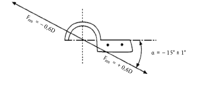
3.7.3.1.A sample is attached to one of the grips on the base by the end closest to the 100 mm mark, with its longitudinal axis horizontal and its transverse axis at 45° to the horizontal. Below the test sample, a clean woven metal screen is attached to the second grip and located 10 mm horizontally below the edge of the sample such that the sample protrudes approximately 13 mm beyond the end of the screen (see Figure 9-1). A bath full of water shall be placed on the fume hood table in such a way as to receive any incandescent particles which may fall during the test.
3.7.3.2.The air supply to the burner shall be set in such a way as to obtain a blue flame with an approximate height of 25 mm.
3.7.3.3.The burner shall be placed so that its flame touches the outer edge of the test sample (see Figure 1) at the same time the timer is started.
The flame is held in contact for 30 seconds. If the sample deforms, melts or shrinks away, the flame shall be repositioned in order to maintain contact with it. However, significant deformation of the sample during the test may invalidate the result.
The burner shall be withdrawn after 30 seconds or when the flame-front reaches the 25 mm mark, whichever occurs first. The burner shall be moved away at least 450 mm from the sample and the fume hood shall be closed.
3.7.3.4.When the flame front reaches the 25 mm mark, the indicated time in seconds shall be noted as time t1.
3.7.3.5.The timer is stopped when combustion (with or without flame) stops or reaches the mark 100 mm from the free end. The indicated time shall be noted as time t. When a sample is reignited by burning material deposited on the woven metal screen, the test result may be invalidated.
3.7.3.6.If the combustion does not reach the 100 mm mark, the unburnt length from the 100 mm mark along the lower edge of the sample is measured and rounded up or down to the nearest millimetre. The burnt length is thus equal to 100 mm minus the unburnt length expressed in mm.
3.7.3.7.If a sample has burnt up to or beyond the 100 mm mark, the combustion speed shall be calculated as follows:  and expressed in mm/s.
3.7.3.8.The test described in points 3.7.3.1 to 3.7.3.7 shall be repeated on different samples until three samples have burnt up to or beyond the 100 mm mark or ten samples have been tested.
3.7.3.9.If only one sample out of ten burns up to the 100 mm mark or beyond, the test described in points 3.7.3.1 to 3.7.3.7 shall be repeated on a maximum of ten new samples.
3.7.4.Expression of results
3.7.4.1.The test report shall contain at least the following detailed information:
number of samples tested,
and concerning each of the individual samples:
means of identification,
method of preparation and storage,
thickness measured in each third of the sample’s length (mm with at least one decimal),
combustion time (s),
combustion length (mm),
statement and reason where a sample does not burn up to the 100 mm mark (e.g. because it drips, runs or breaks up into burnt particles),
statement when a sample is reignited by burning material deposited on the woven metal screen.
3.7.4.2.If at least two samples have burnt up to or beyond the 100 mm mark, the average speed of combustion (expressed in mm/s and as derived from the multiple results calculated in accordance with the formula in point 3.7.3.7) shall be determined. The average speed of combustion is thus the average of the combustion speeds of all of the samples that have burnt up to or beyond the 100 mm mark. This value shall be compared against the requirement in points 3.7.5 to 3.7.5.1 and the calculations and verification referred to in point 3.7.4.3 shall not be carried out.
3.7.4.3.The average combustion time (ACT) and average combustion length (ACL) shall be calculated if no sample out of ten or no more than one out of 20 has burnt up to the 100 mm mark.
Equation 9-1:

where n is the number of samples.
The result is rounded up or down to the nearest five-second increment. However, an ACT of 0 seconds shall not be used. (i.e. if the combustion lasts between less than 2 seconds and 7 seconds, the ACT is 5 seconds; if the combustion lasts between 8 and 12 seconds, the ACT is 10 seconds; if the combustion lasts between 13 and 17 seconds, the ACT is 15 seconds, etc.).
Equation 9-2:

where n is the number of samples.
The result is expressed in relation to the nearest 5 mm increment (i.e. ‘less than 5 mm’ shall be stated if the combustion length is less than 2 mm and thus in no case can an ACL of 0 mm be given).
Where a single sample out of 20 burns up to or beyond the 100 mm mark, the combustion length (i.e. the value of (100 – unburnt lengthi) for that sample) shall be taken as 100 mm.
Equation 9-3:
The average speed of combustion is thus (ACL/ACT) (expressed in mm/s).
This value shall be compared against the requirement as laid down in points 3.7.5 to 3.7.5.1.
3.7.5.Requirements concerning the fire resistance of fuel tank materials other than metal
3.7.5.1.The fuel tank material shall not burn at an average speed of combustion greater than 0,64 mm/s as determined in accordance with the test procedure laid down in points 3.7 to 3.7.4.3.
Options/Help
Print Options
PrintThe Whole Regulation
PrintThe Whole Annex
You have chosen to open the Whole Regulation
The Whole Regulation you have selected contains over 200 provisions and might take some time to download. You may also experience some issues with your browser, such as an alert box that a script is taking a long time to run.
Would you like to continue?
You have chosen to open Schedules only
The Schedules you have selected contains over 200 provisions and might take some time to download. You may also experience some issues with your browser, such as an alert box that a script is taking a long time to run.
Would you like to continue?
Legislation is available in different versions:
Latest Available (revised):The latest available updated version of the legislation incorporating changes made by subsequent legislation and applied by our editorial team. Changes we have not yet applied to the text, can be found in the ‘Changes to Legislation’ area.
Original (As adopted by EU): The original version of the legislation as it stood when it was first adopted in the EU. No changes have been applied to the text.
Opening Options
Different options to open legislation in order to view more content on screen at once
More Resources
Access essential accompanying documents and information for this legislation item from this tab. Dependent on the legislation item being viewed this may include:
- the original print PDF of the as adopted version that was used for the EU Official Journal
- lists of changes made by and/or affecting this legislation item
- all formats of all associated documents
- correction slips
- links to related legislation and further information resources
More Resources
Use this menu to access essential accompanying documents and information for this legislation item. Dependent on the legislation item being viewed this may include:
- the original print PDF of the as adopted version that was used for the print copy
- correction slips
Click 'View More' or select 'More Resources' tab for additional information including:
- lists of changes made by and/or affecting this legislation item
- confers power and blanket amendment details
- all formats of all associated documents
- links to related legislation and further information resources
 All content is available under the Open Government Licence v3.0 except where otherwise stated. This site additionally contains content derived from EUR-Lex, reused under the terms of the Commission Decision 2011/833/EU on the reuse of documents from the EU institutions. For more information see the EUR-Lex public statement on re-use.