- Latest available (Revised)
- Original (As adopted by EU)
Regulation (EU) No 540/2014 of the European Parliament and of the CouncilShow full title
Regulation (EU) No 540/2014 of the European Parliament and of the Council of 16 April 2014 on the sound level of motor vehicles and of replacement silencing systems, and amending Directive 2007/46/EC and repealing Directive 70/157/EEC (Text with EEA relevance)
You are here:

What Version
Advanced Features
- Show Geographical Extent(e.g. England, Wales, Scotland and Northern Ireland)
- Show Timeline of Changes
More Resources
Revised version PDFs
- Revised 27/05/20191.10 MB
- Revised 22/09/20171.01 MB
- Revised 16/06/20140.84 MB
Legislation originating from the EU
When the UK left the EU, legislation.gov.uk published EU legislation that had been published by the EU up to IP completion day (31 December 2020 11.00 p.m.). On legislation.gov.uk, these items of legislation are kept up-to-date with any amendments made by the UK since then.


This item of legislation originated from the EU
Legislation.gov.uk publishes the UK version. EUR-Lex publishes the EU version. The EU Exit Web Archive holds a snapshot of EUR-Lex’s version from IP completion day (31 December 2020 11.00 p.m.).
Changes over time for: ANNEX II
Changes to legislation:
There are outstanding changes not yet made to Regulation (EU) No 540/2014 of the European Parliament and of the Council. Any changes that have already been made to the legislation appear in the content and are referenced with annotations.
Changes to Legislation
Revised legislation carried on this site may not be fully up to date. Changes and effects are recorded by our editorial team in lists which can be found in the ‘Changes to Legislation’ area. Where those effects have yet to be applied to the text of the legislation by the editorial team they are also listed alongside the legislation in the affected provisions. Use the ‘more’ link to open the changes and effects relevant to the provision you are viewing.
Changes and effects yet to be applied to Annex II:
- Regulation power to amend conferred by 2024 c. 10 s. 91
- Annex 2 words substituted by S.I. 2022/1273 reg. 76(3)
Changes and effects yet to be applied to the whole legislation item and associated provisions
- Signature words omitted by S.I. 2022/1273 reg. 75(10)
- Annex 7 s. 1 words substituted by S.I. 2022/1273 reg. 76(7)
- Annex 8 s. 3.5 words substituted by S.I. 2022/1273 reg. 76(8)
- Annex 4 s. 1 words substituted by S.I. 2022/1273 reg. 76(5)
- Annex 9 Appendix 3 image substituted by S.I. 2022/1273 reg. 76(9)(n)(i)
- Annex 9 Appendix 1 point 1.5 word substituted by S.I. 2022/1273 reg. 76(9)(k)
- Annex 9 Appendix 2 Addendum word substituted by S.I. 2022/1273 reg. 76(9)(l)
- Annex 9 Appendix 3 image words omitted by S.I. 2022/1273 reg. 76(9)(n)(ii)
- Annex 9 Appendix 2 notes words substituted by S.I. 2022/1273 reg. 76(9)(m)
- Annex 6 s. 3 words substituted by S.I. 2022/1273 reg. 76(6)
- Annex 1 Appendix 2 heading word substituted by S.I. 2022/1273 reg. 76(2)(j)(i)
- Annex 1 Appendix 2 Addendum word substituted by S.I. 2022/1273 reg. 76(2)(l)
- Annex 1 Appendix 2 words inserted by S.I. 2022/1273 reg. 76(2)(j)(ii)
- Annex 1 Appendix 1 heading words substituted by S.I. 2022/1273 reg. 76(2)(i)(i)
- Annex 1 Appendix 1 point 9(1) words substituted by S.I. 2022/1273 reg. 76(2)(i)(ii)
- Annex 1 Appendix 2 notes words substituted by S.I. 2022/1273 reg. 76(2)(k)(i)
- Annex 1 Appendix 2 notes words substituted by S.I. 2022/1273 reg. 76(2)(k)(ii)
- Art. 3(1) words substituted by S.I. 2022/1273 reg. 75(4)(b)
- Art. 3(5) words substituted by S.I. 2022/1273 reg. 75(4)(c)
- Art. 3(21) word substituted by S.I. 2022/1273 reg. 75(4)(d)
ANNEX IIU.K.METHODS AND INSTRUMENTS FOR MEASURING THE NOISE MADE BY MOTOR VEHICLES
1.METHODS OF MEASUREMENTU.K.
1.1.The noise made by the vehicle type submitted for EU type-approval shall be measured by the two methods described in this Annex for the vehicle in motion and for the vehicle when stationary. In the case of a hybrid electric vehicle where an internal combustion engine cannot operate when the vehicle is stationary, the emitted noise shall only be measured in motion.U.K.
Vehicles having a technically permissible maximum laden mass exceeding 2800 kg shall be subjected to an additional measurement of the compressed air noise with the vehicle stationary in accordance with the specifications of Annex V, if the corresponding brake equipment is part of the vehicle.
1.2.The values measured in accordance with the tests set out in point 1.1 of this Annex shall be entered in the test report and on a form conforming to the model contained in Appendix 2 to Annex I.U.K.
2.MEASURING INSTRUMENTSU.K.
2.1.Acoustic measurementsU.K.
The apparatus used for measuring the sound level shall be a precision sound-level meter or equivalent measurement system meeting the requirements of class 1 instruments (inclusive of the recommended windscreen, if used). Those requirements are described in ‘IEC 61672-1:2002: Precision sound level meters’, second edition, of the International Electrotechnical Commission (IEC).
Measurements shall be carried out using the ‘fast’ response of the acoustic measurement instrument and the ‘A’ weighting curve also described in ‘IEC 61672-1:2002’. When using a system that includes a periodic monitoring of the A-weighted sound pressure level, a reading shall be made at a time interval not greater than 30 ms (milliseconds).
The instruments shall be maintained and calibrated in accordance with the instructions of the instrument manufacturer.
2.2.Compliance with requirementsU.K.
Compliance of the acoustic measurement instrumentation shall be verified by the existence of a valid certificate of compliance. A certificate of compliance shall be deemed to be valid if certification of compliance with the standards was conducted within the previous 12-month period for the sound calibration device and within the previous 24-month period for the instrumentation system. All compliance testing shall be conducted by a laboratory, which is authorised to perform calibrations traceable to the appropriate standards.
2.3.Calibration of the entire Acoustic Measurement System for measurement sessionU.K.
At the beginning and at the end of every measurement session, the entire acoustic measurement system shall be checked by means of a sound calibrator that complies with the requirements for sound calibrators of precision class 1 as set out in IEC 60942: 2003. Without any further adjustment the difference between the readings shall be less than or equal to 0,5 dB. If that value is exceeded, the results of the measurements obtained after the previous satisfactory check shall be discarded.
2.4.Instrumentation for speed measurementsU.K.
The engine speed shall be measured with instrumentation having an accuracy of ± 2 % or better at the engine speeds required for the measurements being performed.
The road speed of the vehicle shall be measured with instrumentation having an accuracy of at least ± 0,5 km/h, when using continuous measurement devices.
If testing uses independent measurements of speed, this instrumentation shall meet specification limits of at least ± 0,2 km/h.
2.5.Meteorological instrumentationU.K.
The meteorological instrumentation used to monitor the environmental conditions during the test shall include the following devices, which meet at least the accuracies listed below:
temperature measuring device, ± 1 °C;
wind speed-measuring device, ± 1,0 m/s;
barometric pressure measuring device, ± 5 hPa;
a relative humidity measuring device, ± 5 %.
3.CONDITIONS OF MEASUREMENTU.K.
3.1.Test Site and ambient conditionsU.K.
3.1.1.The surface of the test track and the dimensions of the test site shall be in accordance with ISO 10844:2011. The surface of the site shall be free of powdery snow, tall grass, loose soil or cinders. There shall be no obstacle which could affect the sound field within the vicinity of the microphone and the sound source. The observer carrying out the measurements shall so position himself as not to affect the readings of the measuring instrument.U.K.
3.1.2.Measurements shall not be made under adverse weather conditions. It shall be ensured that the results are not affected by gusts of wind.U.K.
The meteorological instrumentation shall be positioned adjacent to the test area at a height of 1,2 m ± 0,02 m. The measurements shall be made when the ambient air temperature is between + 5 °C and + 40 °C.
The tests shall not be carried out if the wind speed, including gusts, at microphone height exceeds 5 m/s, during the noise measurement interval.
A value representative of temperature, wind speed and direction, relative humidity, and barometric pressure shall be recorded during the noise measurement interval.
Any noise peak which appears to be unrelated to the characteristics of the general sound level of the vehicle shall be ignored in taking the readings.
The background noise shall be measured for a duration of 10 seconds immediately before and after a series of vehicle tests. The measurements shall be made with the same microphones and microphone locations used during the test. The A-weighted maximum noise pressure level shall be reported.
The background noise (including any wind noise) shall be at least 10 dB below the A-weighted noise pressure level produced by the vehicle under test. If the difference between the ambient noise and the measured noise is between 10 and 15 dB(A), the appropriate correction shall be subtracted from the readings on the noise-level meter in order to calculate the test results, as in the following table:
| Difference between ambient noise and noise to be measured dB(A) | 10 | 11 | 12 | 13 | 14 | 15 |
| Correction dB(A) | 0,5 | 0,4 | 0,3 | 0,2 | 0,1 | 0,0 |
3.2.VehicleU.K.
3.2.1.The vehicle tested shall be representative of vehicles to be put on the market and selected by the manufacturer in agreement with the technical service, to comply with the requirements of this Regulation. Measurements shall be made without any trailer, except in the case of non-separable vehicles. At the request of the manufacturer, measurements may be made on vehicles with lift axle(s) in a raised position.U.K.
Measurements shall be made on vehicles at the test mass mt specified in accordance with the following table:
| Vehicle Category | Vehicle test mass (mt) |
|---|---|
| M1 | mt = mro |
| N1 | mt = mro |
| N2, N3 | mt = 50 kg per kW rated engine power Extra loading to reach the test mass of the vehicle shall be placed above the driven rear axle(s). The extra loading is limited to 75 % of the technically permissible maximum laden mass allowed for the rear axle. The test mass shall be achieved with a tolerance of ± 5 %. If the centre of gravity of the extra loading cannot be aligned with the centre of the rear axle, the test mass of the vehicle shall not exceed the sum of the front axle and the rear axle load in unladen condition plus the extra loading. The test mass for vehicles with more than two axles shall be the same as for a two-axle vehicle. |
| M2, M3 | mt = mro — mass of the crew member (if applicable) or, if the tests are carried out on an incomplete vehicle not having bodywork, mt = 50 kg per kW rated engine power respectively in compliance with conditions above (see category N2, N3). |
3.2.2.At the applicant's request, the vehicle of a category M2, M3, N2 or N3 shall be deemed representative of its completed type if the tests are carried out on an incomplete vehicle not having bodywork. In the test of an incomplete vehicle, all relevant soundproofing materials, panels and noise reduction components and systems shall be fitted on the vehicle as designed by the manufacturer except a part of bodywork which is built at a later stage.U.K.
No new test shall be required due to the fitting of a supplement fuel tank or re-location of the original fuel tank on the condition that other parts or structures of the vehicle apparently affecting sound emissions have not been altered.
3.2.3.Tyre rolling sound emissions are laid down in Regulation (EC) No 661/2009. The tyres to be used for the test shall be representative for the vehicle and shall be selected by the vehicle manufacturer and recorded in Addendum to Appendix 2 to Annex I to this Regulation. They shall correspond to one of the tyre sizes designated for the vehicle as original equipment. The tyre is or will be commercially available on the market at the same time as the vehicle(1). The tyres shall be inflated to the pressure recommended by the vehicle manufacturer for the test mass of the vehicle. The tyres shall have at least 1,6 mm tread depth.U.K.
3.2.4.Before the measurements are started, the engine shall be brought to its normal operating conditions.U.K.
3.2.5.If the vehicle is fitted with more than two-wheel drive, it shall be tested in the drive which is intended for normal road use.U.K.
3.2.6.If the vehicle is fitted with one or more fans having an automatic actuating mechanism, this system shall not be interfered with during the measurements.U.K.
3.2.7.If the vehicle is equipped with a silencing system containing fibrous materials, the exhaust system is to be conditioned before the test in accordance with Annex IV.U.K.
4.METHODS OF TESTINGU.K.
4.1.Measurement of noise of vehicles in motionU.K.
4.1.1.General test conditionsU.K.
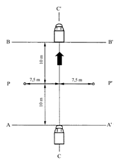
Two lines, AA' and BB', parallel to line PP' and situated respectively 10 m forward and 10 m rearward of line PP' shall be marked out on the test runway.
At least four measurements shall be made on each side of the vehicle and for each gear. Preliminary measurements may be made for adjustment purposes, but shall be disregarded.
The microphone shall be located at a distance of 7,5 m ± 0,05 m from the reference line CC' of the track and 1,2 m ± 0,02 m above the ground.
The reference axis for free field conditions (see IEC 61672-1:2002) shall be horizontal and directed perpendicularly towards the path of the vehicle line CC'.
4.1.2.Specific test conditions for vehiclesU.K.
4.1.2.1.Vehicles of category M1, M2 ≤ 3 500 kg, N1 U.K.
The path of the centreline of the vehicle shall follow line CC' as closely as possible throughout the entire test, from the approach to line AA' until the rear of the vehicle passes line BB'. If the vehicle is fitted with more than two-wheel drive, it shall be tested in the drive selection which is intended for normal road use.
If the vehicle is fitted with an auxiliary manual transmission or a multi-gear axle, the position used for normal urban driving shall be used. In all cases, the gear ratios for slow movements, parking or braking shall be excluded.
The test mass of the vehicle shall be that set out in the Table in point 3.2.1.
The test speed vtest is 50 km/h ± 1 km/h. The test speed shall be reached when the reference point is at line PP'.
4.1.2.1.1.Power to mass ratio index (PMR)U.K.
PMR is calculated using the following formula:
PMR = (Pn/mt) × 1 000 where Pn is measured in kW and mt is measured in kg in accordance with point 3.2.1 of this Annex.
PMR, with no dimension, is used for the calculation of acceleration.
4.1.2.1.2.Calculation of accelerationU.K.
Acceleration calculations are applicable to M1, N1 and M2 ≤ 3 500 kg categories only.
All accelerations are calculated using different speeds of the vehicle on the test track. The formulae given are used for the calculation of awot i, awot i+1 and awot test. The speed either at AA' or PP' is defined as the vehicle speed when the reference point passes AA' (vAA') or PP' (vPP'). The speed at BB' is defined when the rear of the vehicle passes BB' (vBB'). The method used for calculating the acceleration shall be indicated in the test report.
Due to the definition of the reference point for the vehicle, the length of the vehicle (lveh) is considered differently in the formula below. If the reference point is in the front of the vehicle, then l = lveh, mid: l = 1/2 lveh and rear: l = 0.
4.1.2.1.2.1The calculation procedure for vehicles with manual transmission, automatic transmission, adaptive transmissions and continuous variable transmissions (CVTs) tested with locked gear ratios is as follows:U.K.
awot test = ((vBB'/3,6)2 – (vAA'/3,6)2)/(2*(20+l))
awot test used in the determination of gear selection shall be the average of the four awot test, i during each valid measurement run.
Pre-acceleration may be used. The point of depressing the accelerator before line AA' shall be reported in the test report.
4.1.2.1.2.2.The calculation procedure for vehicles with automatic transmissions, adaptive transmissions and CVTs tested with non-locked gear ratios is as follows:U.K.
awot test used in the determination of gear selection shall be the average of the four awot test, i during each valid measurement run.
Where devices or measures described in point 4.1.2.1.4.2 can be used to control transmission operation for the purpose of achieving test requirements, awot test shall be calculated using the following formula:
awot test = ((vBB'/3,6)2 – (vAA'/3,6)2)/(2*(20+l))
Pre-acceleration may be used:
Where devices or measures described in point 4.1.2.1.4.2 are not used, awot test shall be calculated using the following formula:
awot_testPP-BB = ((vBB'/3,6)2 – (vPP'/3,6)2)/(2*(10+l))
awot_test PP-BB
:
acceleration between point PP and BB
Pre-acceleration shall not be used.
The location of depressing the accelerator shall be where the reference point of the vehicle passes line AA'.
4.1.2.1.2.3Target accelerationU.K.
The target acceleration a urban defines the typical acceleration in urban traffic and is derived from statistical investigations. It is a function depending on the PMR of a vehicle.
The target acceleration a urban shall be calculated using the following formula:
a urban = 0,63 * log10 (PMR) – 0,09
4.1.2.1.2.4.Reference accelerationU.K.
The reference acceleration awot ref defines the required acceleration during the acceleration test on the test track. It is a function depending on the PMR of a vehicle. That function is different for specific vehicle categories.
The reference acceleration awot ref shall be calculated using the following formula:
a wot ref = 1,59 * log10 (PMR) –1,41 for PMR ≥ 25
a wot ref = a urban = 0,63 * log10 (PMR) – 0,09 for PMR < 25
4.1.2.1.3.Partial power factor kP U.K.
The partial power factor kP (see point 4.1.3.1) is used for the weighted combination of the test results of the acceleration test and the constant speed test for vehicles of category M1 and N1.
In cases other than a single gear test, a wot ref shall be used instead of a wot test (see point 4.1.3.1).
4.1.2.1.4.Gear ratio selectionU.K.
The selection of gear ratios for the test depends on their specific acceleration potential awot under full throttle condition, in accordance with the reference acceleration awot ref required for the full throttle acceleration test.
Some vehicles may have different software programs or modes for the transmission (e.g. sporty, winter, adaptive). Where the vehicle has different modes leading to valid accelerations, the vehicle manufacturer shall prove to the satisfaction of the technical service, that the vehicle is tested in the mode which achieves an acceleration closest to a wot ref.
4.1.2.1.4.1.Vehicles with manual transmissions, automatic transmissions, adaptive transmissions or CVTs tested with locked gear ratiosU.K.
The following conditions for selection of gear ratios are possible:
(a)
if one specific gear ratio gives an acceleration in a tolerance band of ± 5 % of the reference acceleration awot ref, not exceeding 2,0 m/s2, test with that gear ratio.
(b)
if none of the gear ratios give the required acceleration, then choose a gear ratio i, with an acceleration higher and a gear ratio i + 1, with an acceleration lower than the reference acceleration. If the acceleration value in gear ratio i does not exceed 2,0 m/s2, use both gear ratios for the test. The weighting ratio in relation to the reference acceleration awot ref is calculated by:
k = (a wot ref – a wot (i+1))/(a wot (i) – a wot (i+1))
(c)
if the acceleration value of gear ratio i exceeds 2,0 m/s2, the first gear ratio that gives an acceleration below 2,0 m/s2 shall be used unless gear ratio i + 1 provides an acceleration less than aurban. In this case, two gears, i and i + 1 shall be used, including the gear i with the acceleration exceeding 2,0 m/s2. In other cases, no other gear shall be used. The achieved acceleration awot test during the test shall be used for the calculation of the partial power factor kP instead of awot ref.
(d)
if the vehicle has a transmission in which there is only one selection for the gear ratio, the acceleration test shall be carried out in this vehicle gear selection. The achieved acceleration is then used for the calculation of the partial power factor kP instead of awot ref.
(e)
if rated engine speed is exceeded in a gear ratio before the vehicle passes BB' the next higher gear shall be used.
4.1.2.1.4.2.Vehicles with automatic transmission, adaptive transmissions and CVTs tested with non-locked gear ratiosU.K.
The gear selector position for full automatic operation shall be used.
The acceleration value awot test shall be calculated as defined in point 4.1.2.1.2.2.
The test may then include a gear change to a lower range and a higher acceleration. A gear change to a higher range and a lower acceleration is not allowed. A gear shifting to a gear ratio which is not used in urban traffic shall be avoided.
Therefore, it shall be permitted to establish and use electronic or mechanical devices, including alternate gear selector positions, to prevent a downshift to a gear ratio which is typically not used at the specified test condition in urban traffic.
The achieved acceleration awot test shall be greater or equal to aurban.
If possible, the manufacturer shall take measures to avoid an acceleration value awot test greater than 2,0 m/s2.
The achieved acceleration a wot test shall then be used for the calculation of the partial power factor kp (see point 4.1.2.1.3) instead awot ref.
4.1.2.1.5.Acceleration testU.K.
The manufacturer shall define the position of the reference point in front of line AA' of fully depressing the accelerator. The accelerator shall be fully depressed (as rapidly as is practicable) when the reference point of the vehicle reaches the defined point. The accelerator shall be kept in this depressed condition until the rear of the vehicle reaches line BB'. The accelerator shall then be released as rapidly as possible. The point of fully depressing the accelerator shall be reported in the test report. The technical service shall have the possibility of pre-testing.
In the case of articulated vehicles consisting of two non-separable units regarded as a single vehicle, the semi-trailer shall be disregarded in determining when line BB' is crossed.
4.1.2.1.6.Constant speed testU.K.
The constant speed test shall be carried out with the same gear(s) specified for the acceleration test and a constant speed of 50 km/h with a tolerance of ± 1 km/h between AA' and BB'. During the constant speed test, the acceleration control shall be positioned to maintain a constant speed between AA' and BB' as specified. If the gear is locked for the acceleration test, the same gear shall be locked for the constant speed test.
The constant speed test is not required for vehicles with a PMR < 25.
4.1.2.2.Vehicles of categories M2 > 3 500 kg, M3, N2, N3 U.K.
The path of the centreline of the vehicle shall follow line CC' as closely as possible throughout the entire test, from the approach to line AA' until the rear of the vehicle passes line BB'. The test shall be conducted without a trailer or semi-trailer. If a trailer is not readily separable from the towing vehicle, the trailer shall not be taken into consideration when assessing the crossing of line BB'. If the vehicle incorporates equipment such as a concrete mixer, a compressor, etc., this equipment shall not be in operation during the test. The test mass of the vehicle shall be set out in the table set out in point 3.2.1.
Target conditions of category M2 > 3 500 kg, N2
When the reference point passes line BB', the engine speed nBB' shall be between 70 % and 74 % of speed S, at which the engine develops its rated maximum power, and the vehicle speed shall be 35 km/h ± 5 km/h. Between line AA' and line BB' a stable acceleration condition shall be ensured.
Target conditions of category M3, N3:
When the reference point passes line BB', the engine speed nBB' shall be between 85 % and 89 % of speed S, at which the engine develops its rated maximum power, and the vehicle speed shall be 35 km/h ± 5 km/h. Between line AA' and line BB' a stable acceleration condition shall be ensured.
4.1.2.2.1.Gear ratio selectionU.K.
4.1.2.2.1.1.Vehicles with manual transmissionsU.K.
Stable acceleration conditions shall be ensured. The gear choice shall be determined by the target conditions. If the difference in speed exceeds the given tolerance, then two gears shall be tested, one above and one below the target speed.
If more than one gear fulfils the target conditions, the gear which is closest to 35 km/h shall be used. If no gear fulfils the target condition for vtest, two gears shall be tested, one above and one below vtest. The target engine speed shall be reached under all conditions.
A stable acceleration condition shall be ensured. If a stable acceleration cannot be ensured in a gear, that gear shall be disregarded.
4.1.2.2.1.2.Vehicles with automatic transmissions, adaptive transmissions and CVTsU.K.
The gear selector position for full automatic operation shall be used. The test may then include a gear change to a lower range and a higher acceleration. A gear change to a higher range and a lower acceleration shall not be permitted. A gear shifting to a gear ratio which is not used in urban traffic, at the specified test condition, shall be avoided. Therefore, it shall be permitted to establish and use electronic or mechanical devices to prevent a downshift to a gear ratio which is typically not used at the specified test condition in urban traffic.
If the vehicle includes a transmission design, which provides only a single gear selection (drive), which limits engine speed during the test, the vehicle shall be tested using only a target vehicle speed. If the vehicle uses an engine and transmission combination that does not comply with the requirements set out in point 4.1.2.2.1.1, the vehicle shall be tested using only the target vehicle speed. The target vehicle speed (vBB') for the test is = 35 km/h ± 5km/h. A gear change to a higher range and a lower acceleration is allowed after the reference point of the vehicle passes line PP'. Two tests shall be performed, one with the end speed of vtest = vBB' + 5 km/h, and one with the end speed of vtest = vBB' – 5 km/h. The reported sound level shall be the result of the test with the highest engine speed obtained during the test from AA' to BB'.
4.1.2.2.2.Acceleration testU.K.
When the reference point of the vehicle reaches the line AA' the accelerator control shall be fully depressed (without operating the automatic downshift to a lower range than normally used in urban driving) and held fully depressed until the rear of the vehicle passes BB', but the reference point shall be at least 5 m behind BB'. The accelerator control shall then be released.
In the case of articulated vehicles consisting of two non-separable units regarded as a single vehicle, the semi-trailer shall be disregarded in determining when line BB' is crossed.
4.1.3.Interpretation of resultsU.K.
The maximum A-weighted sound pressure level indicated during each passage of the vehicle between the two lines AA' and BB' shall be noted. If a noise peak obviously out of character with the general sound pressure level is observed, the measurement shall be discarded. At least four measurements for each test condition shall be made on each side of the vehicle and for each gear ratio. Left and right side may be measured simultaneously or sequentially. The first four valid consecutive measurement results, within 2 dB(A), allowing for the deletion of non valid results (see point 3.1), shall be used for the calculation of the final result for the given side of the vehicle. The results of each side shall be averaged separately. The intermediate result is the higher value of the two averages mathematically rounded to the first decimal place.
The speed measurements at AA', BB', and PP' shall be noted and used in calculations to the first significant digit after the decimal place.
The calculated acceleration awot test shall be noted to the second digit after the decimal place.
4.1.3.1.Vehicles of categories M1, N1 and M2 ≤ 3 500 kgU.K.
The calculated values for the acceleration test and the constant speed test are given by:
Lwot rep = Lwot (i+1) + k * (Lwot(i) – Lwot (i+1))
Lcrs rep = Lcrs(i+1) + k * (Lcrs (i) – Lcrs (i+1))
Where k = (awot ref – awot (i+1))/(awot (i) – awot (i+1))
In the case of a single gear ratio test, the values are the test result of each test.
The final result is calculated by combining Lwot rep and Lcrs rep. The equation is:
Lurban = Lwot rep – kP * (Lwot rep – Lcrs rep)
The weighting factor kP, gives the partial power factor for urban driving. In cases other than a single gear test kP is calculated by:
kP = 1 – (aurban/awot ref)
If only one gear was specified for the test kP is given by:
kP = 1 – (aurban/awot test)
In cases where awot test is less than aurban:
kP = 0
4.1.3.2.Vehicles of categories M2 > 3 500 kg, M3, N2, N3 U.K.
When one gear is tested, the final result shall be equal to the intermediate result. When two gears are tested the arithmetic mean of the intermediate results shall be calculated.
4.2.Measurement of noise emitted by stationary vehiclesU.K.
4.2.1.Sound level in the vicinity of vehiclesU.K.
The measurement results shall be entered into the test report referred to in the Addendum to Appendix 2 to Annex I.
4.2.2.Acoustic measurementsU.K.
A precision sound level meter, or equivalent measuring system, as defined in point 2.1 shall be used for the measurements
4.2.3.Test site — local conditions as referred to in Figures 2 and 3a to 3d of the Appendix.U.K.
4.2.3.1.In the vicinity of the microphone, there shall be no obstacle that could influence the acoustical field and no person shall remain between the microphone and the noise source. The meter observer shall be positioned so as not to influence the meter reading.U.K.
4.2.4.Disturbance sound and wind interferenceU.K.
Readings on the measuring instruments produced by ambient noise and wind shall be at least 10 dB(A) below the sound level to be measured. A suitable windscreen may be fitted to the microphone provided that account is taken of its effect on the sensitivity of the microphone (see point 2.1).
4.2.5.Measuring methodU.K.
4.2.5.1.Nature and number of measurementsU.K.
The maximum sound level expressed in A-weighted decibels (dB(A)) shall be measured during the operating period referred to in point 4.2.5.3.2.1.
At least three measurements shall be taken at each measuring point.
4.2.5.2.Positioning and preparation of the vehicleU.K.
The vehicle shall be located in the centre part of the test area with the gear selector in the neutral position and the clutch engaged. If the design of the vehicle does not allow this, the vehicle shall be tested in conformity with the manufacturer's prescriptions for stationary engine testing. Before each series of measurements, the engine shall be brought to its normal operating condition, as specified by the manufacturer.
If the vehicle is fitted with a fan or fans having an automatic actuating mechanism, this system shall not be interfered with during the sound level measurements.
The engine hood or compartment cover, if so fitted, shall be closed.
4.2.5.3.Measuring of noise in proximity to the exhaust as referred to in Figure 2 and Figures 3a to 3d of the Appendix.U.K.
4.2.5.3.1.Positions of the microphoneU.K.
4.2.5.3.1.1.The microphone shall be located at a distance of 0,5 m ± 0,01 m from the reference point of the exhaust pipe defined in Figure 2 and Figures 3a to 3d of the Appendix, and at an angle of 45°(± 5°) to the flow axis of the pipe termination. The microphone shall be at the height of the reference point, but not less than 0,2 m from the ground surface. The reference axis of the microphone shall lie in a plane parallel to the ground surface and shall be directed toward the reference point on the exhaust outlet. If two microphone positions are possible, the location farthest laterally from the vehicle longitudinal centreline shall be used. If the flow axis of the exhaust outlet pipe is at 90° to the vehicle longitudinal centreline, the microphone shall be located at the point, which is farthest from the engine.U.K.
4.2.5.3.1.2.For vehicles having an exhaust provided with outlets spaced more than 0,3 m apart, measurements shall be made for each outlet. The highest level shall be recorded.U.K.
4.2.5.3.1.3.In the case of an exhaust provided with two or more outlets spaced less than 0,3 m apart and which are connected to the same silencer, only one measurement shall be made; the microphone position is related to the outlet nearest to one extreme edge of the vehicle or, when such outlet does not exist, to the outlet which is the highest above the ground.U.K.
4.2.5.3.1.4.For vehicles with a vertical exhaust (e.g. commercial vehicles) the microphone shall be placed at the height of the exhaust outlet. Its axis shall be vertical and oriented upwards. It shall be placed at a distance of 0,5 m ± 0,01 m from the exhaust pipe reference point, but never less than 0,2 m from the side of the vehicle nearest to the exhaust.U.K.
4.2.5.3.1.5.For exhaust outlets located under the vehicle body, the microphone shall be located a minimum of 0,2 m from the nearest part of the vehicle, at a point closest to, but never less than 0,5 m from the exhaust pipe reference point, and at a height of 0,2 m above the ground, and not in line with the exhaust flow. If it is not physically possible, the angularity requirement in point 4.2.5.3.1.1 need not be met.U.K.
4.2.5.3.1.6.Examples of the position of the microphone, depending on the location of the exhaust pipe, are given in Figures 3a-3d of the Appendix.U.K.
4.2.5.3.2.Operating conditions of the engineU.K.
4.2.5.3.2.1.Target engine speedU.K.
75 % of the engine speed S for vehicles with a rated engine speed ≤ 5 000 min-1
3 750 min-1 for vehicles with a rated engine speed above 5 000 min-1 and below 7 500 min-1
50 % of the engine speed S for vehicles with a rated engine speed ≥ 7 500 min-1.
If the vehicle cannot reach such engine speed, the target engine speed shall be 5 % below the maximum possible engine speed for that stationary test.
4.2.5.3.2.2.Test procedureU.K.
The engine speed shall be gradually increased from idle to the target engine speed, not exceeding a tolerance band of ± 3 % of the target engine speed, and held constant. Then the throttle control shall be rapidly released and the engine speed shall return to idle. The sound level shall be measured during a period of operation consisting of maintaining constant engine speed of 1 second and throughout the entire deceleration period. The maximum sound level meter reading during this period of operation, mathematically rounded to the first decimal place, shall be taken as the test value.
4.2.5.3.2.3.Test validationU.K.
The measurement shall be regarded as valid if the test engine speed does not deviate from the target engine speed by more than ± 3 % for at least 1 second.
4.2.6.ResultsU.K.
At least three measurements for each test position shall be made. The maximum A-weighted sound pressure level indicated during each of the three measurements shall be recorded. The first three valid consecutive measurement results, within 2 dB(A), allowing for the deletion of non valid results (taking into account the specifications of the test site as referred to in point 3.1), shall be used for the determination of the final result for the given measurement position. The maximum sound level, for all measurement positions, and of the three measurement results, shall constitute the final result.
5.Noise from hybrid electric vehicles of categories M1 in motion, where an internal combustion engine cannot operate when the vehicle is stationary (data reported to facilitate testing of the vehicle in use).U.K.
5.1.In order to facilitate in-use compliance testing of hybrid electric vehicles — where an internal combustion engine cannot operate when the vehicle is stationary — the following information relating to the sound-pressure level measurements carried out in accordance with point 4.1 of Annex II for the motor vehicles in motion is referred to as in-use compliance reference data:U.K.
(a)
gear (i) or, for vehicles tested with non-locked gear ratios, the position of the gear selector chosen for the test;
(b)
position of the operating switch during measurement of the sound pressure level Lwot,(i) (if switch is fitted).
(c)
pre-acceleration length lPA in m;
(d)
average vehicle speed in km/h at the beginning of the full throttle acceleration for tests in gear (i); and
(e)
sound pressure level Lwot,(i) in dB(A) of the wide-open-throttle tests in gear (i), defined as the maximum of the two values resulting from averaging the individual measurement results at each microphone position separately.
5.2.The in-use compliance reference data shall be entered in the EU type-approval certificate as specified in point 2.3 of the Addendum to Appendix 2 to Annex I.U.K.
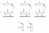
AppendixFigures
T
=
top view
S
=
side view
A
=
metered pipe
B
=
bent down pipe
C
=
straight pipe
D
=
vertical pipe
1
=
reference point
2
=
road surface


Figures 3 a — d
:
Examples of the position of the microphone, depending on the location of the exhaust pipe
(1)
Given that the tyre contribution for overall sound emission is significant, regard must be had for existing regulatory provisions concerning tyre/road sound emissions. Traction tyres, snow tyres and special-use tyres as defined in paragraph 2 of UNECE Regulation No 117 shall be excluded during type-approval and conformity of production measurements at the request of the manufacturer in accordance with UNECE Regulation No 117 (OJ L 307, 23.11.2011, p. 3).
Options/Help
Print Options
PrintThe Whole Regulation
PrintThis Annex only
You have chosen to open the Whole Regulation
The Whole Regulation you have selected contains over 200 provisions and might take some time to download. You may also experience some issues with your browser, such as an alert box that a script is taking a long time to run.
Would you like to continue?
You have chosen to open Schedules only
The Schedules you have selected contains over 200 provisions and might take some time to download. You may also experience some issues with your browser, such as an alert box that a script is taking a long time to run.
Would you like to continue?
Legislation is available in different versions:
Latest Available (revised):The latest available updated version of the legislation incorporating changes made by subsequent legislation and applied by our editorial team. Changes we have not yet applied to the text, can be found in the ‘Changes to Legislation’ area.
Original (As adopted by EU): The original version of the legislation as it stood when it was first adopted in the EU. No changes have been applied to the text.
See additional information alongside the content
Geographical Extent: Indicates the geographical area that this provision applies to. For further information see ‘Frequently Asked Questions’.
Show Timeline of Changes: See how this legislation has or could change over time. Turning this feature on will show extra navigation options to go to these specific points in time. Return to the latest available version by using the controls above in the What Version box.
Opening Options
Different options to open legislation in order to view more content on screen at once
More Resources
Access essential accompanying documents and information for this legislation item from this tab. Dependent on the legislation item being viewed this may include:
- the original print PDF of the as adopted version that was used for the EU Official Journal
- lists of changes made by and/or affecting this legislation item
- all formats of all associated documents
- correction slips
- links to related legislation and further information resources
Timeline of Changes
This timeline shows the different versions taken from EUR-Lex before exit day and during the implementation period as well as any subsequent versions created after the implementation period as a result of changes made by UK legislation.
The dates for the EU versions are taken from the document dates on EUR-Lex and may not always coincide with when the changes came into force for the document.
For any versions created after the implementation period as a result of changes made by UK legislation the date will coincide with the earliest date on which the change (e.g an insertion, a repeal or a substitution) that was applied came into force. For further information see our guide to revised legislation on Understanding Legislation.
More Resources
Use this menu to access essential accompanying documents and information for this legislation item. Dependent on the legislation item being viewed this may include:
- the original print PDF of the as adopted version that was used for the print copy
- correction slips
Click 'View More' or select 'More Resources' tab for additional information including:
- lists of changes made by and/or affecting this legislation item
- confers power and blanket amendment details
- all formats of all associated documents
- links to related legislation and further information resources
 All content is available under the Open Government Licence v3.0 except where otherwise stated. This site additionally contains content derived from EUR-Lex, reused under the terms of the Commission Decision 2011/833/EU on the reuse of documents from the EU institutions. For more information see the EUR-Lex public statement on re-use.