- Latest available (Revised)
- Point in Time (31/01/2020)
- Original (As adopted by EU)
Commission Regulation (EU) 2016/631Show full title
Commission Regulation (EU) 2016/631 of 14 April 2016 establishing a network code on requirements for grid connection of generators (Text with EEA relevance)
You are here:

What Version
Advanced Features
- Show Geographical Extent(e.g. England, Wales, Scotland and Northern Ireland)
- Show Timeline of Changes
Opening Options
More Resources
Legislation originating from the EU
When the UK left the EU, legislation.gov.uk published EU legislation that had been published by the EU up to IP completion day (31 December 2020 11.00 p.m.). On legislation.gov.uk, these items of legislation are kept up-to-date with any amendments made by the UK since then.


This item of legislation originated from the EU
Legislation.gov.uk publishes the UK version. EUR-Lex publishes the EU version. The EU Exit Web Archive holds a snapshot of EUR-Lex’s version from IP completion day (31 December 2020 11.00 p.m.).
Changes over time for: TITLE II
Version Superseded: 31/12/2020
Alternative versions:
Status:
Point in time view as at 31/01/2020.
Changes to legislation:
There are currently no known outstanding effects by UK legislation for Commission Regulation (EU) 2016/631, TITLE II.
Changes to Legislation
Revised legislation carried on this site may not be fully up to date. At the current time any known changes or effects made by subsequent legislation have been applied to the text of the legislation you are viewing by the editorial team. Please see ‘Frequently Asked Questions’ for details regarding the timescales for which new effects are identified and recorded on this site.
TITLE IIU.K. REQUIREMENTS
CHAPTER 1 U.K. General requirements
Article 13U.K.General requirements for type A power-generating modules
1.Type A power-generating modules shall fulfil the following requirements relating to frequency stability:
(a)With regard to frequency ranges:
(i)
a power-generating module shall be capable of remaining connected to the network and operate within the frequency ranges and time periods specified in Table 2;
(ii)
the relevant system operator, in coordination with the relevant TSO, and the power-generating facility owner may agree on wider frequency ranges, longer minimum times for operation or specific requirements for combined frequency and voltage deviations to ensure the best use of the technical capabilities of a power-generating module, if it is required to preserve or to restore system security;
(iii)
the power-generating facility owner shall not unreasonably withhold consent to apply wider frequency ranges or longer minimum times for operation, taking account of their economic and technical feasibility.
(b)With regard to the rate of change of frequency withstand capability, a power-generating module shall be capable of staying connected to the network and operate at rates of change of frequency up to a value specified by the relevant TSO, unless disconnection was triggered by rate-of-change-of-frequency-type loss of mains protection. The relevant system operator, in coordination with the relevant TSO, shall specify this rate-of-change-of-frequency-type loss of mains protection.
Table 2
Minimum time periods for which a power-generating module has to be capable of operating on different frequencies, deviating from a nominal value, without disconnecting from the network.
| Synchronous area | Frequency range | Time period for operation |
|---|---|---|
| Continental Europe | 47,5 Hz-48,5 Hz | To be specified by each TSO, but not less than 30 minutes |
| 48,5 Hz-49,0 Hz | To be specified by each TSO, but not less than the period for 47,5 Hz-48,5 Hz | |
| 49,0 Hz-51,0 Hz | Unlimited | |
| 51,0 Hz-51,5 Hz | 30 minutes | |
| Nordic | 47,5 Hz-48,5 Hz | 30 minutes |
| 48,5 Hz-49,0 Hz | To be specified by each TSO, but not less than 30 minutes | |
| 49,0 Hz-51,0 Hz | Unlimited | |
| 51,0 Hz-51,5 Hz | 30 minutes | |
| Great Britain | 47,0 Hz-47,5 Hz | 20 seconds |
| 47,5 Hz-48,5 Hz | 90 minutes | |
| 48,5 Hz-49,0 Hz | To be specified by each TSO, but not less than 90 minutes | |
| 49,0 Hz-51,0 Hz | Unlimited | |
| 51,0 Hz-51,5 Hz | 90 minutes | |
| 51,5 Hz-52,0 Hz | 15 minutes | |
| Ireland and Northern Ireland | 47,5 Hz-48,5 Hz | 90 minutes |
| 48,5 Hz-49,0 Hz | To be specified by each TSO, but not less than 90 minutes | |
| 49,0 Hz-51,0 Hz | Unlimited | |
| 51,0 Hz-51,5 Hz | 90 minutes | |
| Baltic | 47,5 Hz-48,5 Hz | To be specified by each TSO, but not less than 30 minutes |
| 48,5 Hz-49,0 Hz | To be specified by each TSO, but not less than the period for 47,5 Hz-48,5 Hz | |
| 49,0 Hz-51,0 Hz | Unlimited | |
| 51,0 Hz-51,5 Hz | To be specified by each TSO, but not less than 30 minutes |
2.With regard to the limited frequency sensitive mode — overfrequency (LFSM-O), the following shall apply, as determined by the relevant TSO for its control area in coordination with the TSOs of the same synchronous area to ensure minimal impacts on neighbouring areas:
(a)the power-generating module shall be capable of activating the provision of active power frequency response according to figure 1 at a frequency threshold and droop settings specified by the relevant TSO;
(b)instead of the capability referred to in paragraph (a), the relevant TSO may choose to allow within its control area automatic disconnection and reconnection of power-generating modules of Type A at randomised frequencies, ideally uniformly distributed, above a frequency threshold, as determined by the relevant TSO where it is able to demonstrate to the relevant regulatory authority, and with the cooperation of power-generating facility owners, that this has a limited cross-border impact and maintains the same level of operational security in all system states;
(c)the frequency threshold shall be between 50,2 Hz and 50,5 Hz inclusive;
(d)the droop settings shall be between 2 % and 12 %;
(e)the power-generating module shall be capable of activating a power frequency response with an initial delay that is as short as possible. If that delay is greater than two seconds, the power-generating facility owner shall justify the delay, providing technical evidence to the relevant TSO;
(f)the relevant TSO may require that upon reaching minimum regulating level, the power-generating module be capable of either:
(i)
continuing operation at this level; or
(ii)
further decreasing active power output;
(g)the power-generating module shall be capable of operating stably during LFSM-O operation. When LFSM-O is active, the LFSM-O setpoint will prevail over any other active power setpoints.

Pref is the reference active power to which ΔΡ is related and may be specified differently for synchronous power-generating modules and power park modules. ΔΡ is the change in active power output from the power-generating module. fn is the nominal frequency (50 Hz) in the network and Δf is the frequency deviation in the network. At overfrequencies where Δf is above Δf1, the power-generating module has to provide a negative active power output change according to the droop S2.
3.The power-generating module shall be capable of maintaining constant output at its target active power value regardless of changes in frequency, except where output follows the changes specified in the context of paragraphs 2 and 4 of this Article or points (c) and (d) of Article 15(2) as applicable.
4.The relevant TSO shall specify admissible active power reduction from maximum output with falling frequency in its control area as a rate of reduction falling within the boundaries, illustrated by the full lines in Figure 2:
(a)below 49 Hz falling by a reduction rate of 2 % of the maximum capacity at 50 Hz per 1 Hz frequency drop;
(b)below 49,5 Hz falling by a reduction rate of 10 % of the maximum capacity at 50 Hz per 1 Hz frequency drop.
5.The admissible active power reduction from maximum output shall:
(a)clearly specify the ambient conditions applicable;
(b)take account of the technical capabilities of power-generating modules.
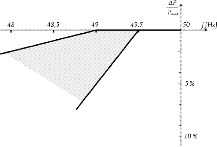
The diagram represents the boundaries in which the capability can be specified by the relevant TSO.
6.The power-generating module shall be equipped with a logic interface (input port) in order to cease active power output within five seconds following an instruction being received at the input port. The relevant system operator shall have the right to specify requirements for equipment to make this facility operable remotely.
7.The relevant TSO shall specify the conditions under which a power-generating module is capable of connecting automatically to the network. Those conditions shall include:
(a)frequency ranges within which an automatic connection is admissible, and a corresponding delay time; and
(b)maximum admissible gradient of increase in active power output.
Automatic connection is allowed unless specified otherwise by the relevant system operator in coordination with the relevant TSO.
Article 14U.K.General requirements for type B power-generating modules
1.Type B power-generating modules shall fulfil the requirements set out in Article 13, except for Article 13(2)(b).
2.Type B power-generating modules shall fulfil the following requirements in relation to frequency stability:
(a)to control active power output, the power-generating module shall be equipped with an interface (input port) in order to be able to reduce active power output following an instruction at the input port; and
(b)the relevant system operator shall have the right to specify the requirements for further equipment to allow active power output to be remotely operated.
3.Type B power-generating modules shall fulfil the following requirements in relation to robustness:
(a)with regard to fault-ride-through capability of power-generating modules:
(i)
each TSO shall specify a voltage-against-time-profile in line with Figure 3 at the connection point for fault conditions, which describes the conditions in which the power-generating module is capable of staying connected to the network and continuing to operate stably after the power system has been disturbed by secured faults on the transmission system;
(ii)
the voltage-against-time-profile shall express a lower limit of the actual course of the phase-to-phase voltages on the network voltage level at the connection point during a symmetrical fault, as a function of time before, during and after the fault;
(iii)
the lower limit referred to in point (ii) shall be specified by the relevant TSO using the parameters set out in Figure 3, and within the ranges set out in Tables 3.1 and 3.2;
(iv)
each TSO shall specify and make publicly available the pre-fault and post-fault conditions for the fault-ride-through capability in terms of:
the calculation of the pre-fault minimum short circuit capacity at the connection point,
pre-fault active and reactive power operating point of the power-generating module at the connection point and voltage at the connection point, and
calculation of the post-fault minimum short circuit capacity at the connection point;
(v)
at the request of a power-generating facility owner, the relevant system operator shall provide the pre-fault and post-fault conditions to be considered for fault-ride-through capability as an outcome of the calculations at the connection point as specified in point (iv) regarding:
pre-fault minimum short circuit capacity at each connection point expressed in MVA,
pre-fault operating point of the power-generating module expressed in active power output and reactive power output at the connection point and voltage at the connection point, and
post-fault minimum short circuit capacity at each connection point expressed in MVA.
Alternatively, the relevant system operator may provide generic values derived from typical cases;
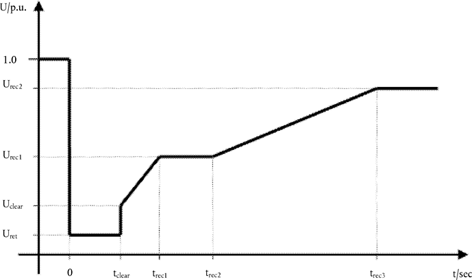
The diagram represents the lower limit of a voltage-against-time profile of the voltage at the connection point, expressed as the ratio of its actual value and its reference 1 pu value before, during and after a fault. Uret is the retained voltage at the connection point during a fault, tclear is the instant when the fault has been cleared. Urec1, Urec2, trec1, trec2 and trec3 specify certain points of lower limits of voltage recovery after fault clearance.
Table 3.1
Parameters for Figure 3 for fault-ride-through capability of synchronous power-generating modules
| Voltage parameters (pu) | Time parameters (seconds) | ||
|---|---|---|---|
| Uret: | 0,05-0,3 | tclear: | 0,14-0,15 (or 0,14-0,25 if system protection and secure operation so require) |
| Uclear: | 0,7-0,9 | trec1: | tclear |
| Urec1: | Uclear | trec2: | trec1-0,7 |
| Urec2: | 0,85-0,9 and ≥ Uclear | trec3: | trec2-1,5 |
Table 3.2
Parameters for Figure 3 for fault-ride-through capability of power park modules
| Voltage parameters (pu) | Time parameters (seconds) | ||
|---|---|---|---|
| Uret: | 0,05-0,15 | tclear: | 0,14-0,15 (or 0,14-0,25 if system protection and secure operation so require) |
| Uclear: | Uret-0,15 | trec1: | tclear |
| Urec1: | Uclear | trec2: | trec1 |
| Urec2: | 0,85 | trec3: | 1,5-3,0 |
(vi)
the power-generating module shall be capable of remaining connected to the network and continuing to operate stably when the actual course of the phase-to-phase voltages on the network voltage level at the connection point during a symmetrical fault, given the pre-fault and post-fault conditions in points (iv) and (v) of paragraph 3(a), remain above the lower limit specified in point (ii) of paragraph 3(a), unless the protection scheme for internal electrical faults requires the disconnection of the power-generating module from the network. The protection schemes and settings for internal electrical faults must not jeopardise fault-ride-through performance;
(vii)
without prejudice to point (vi) of paragraph 3(a), undervoltage protection (either fault-ride-through capability or minimum voltage specified at the connection point voltage) shall be set by the power-generating facility owner according to the widest possible technical capability of the power-generating module, unless the relevant system operator requires narrower settings in accordance with point (b) of paragraph 5. The settings shall be justified by the power-generating facility owner in accordance with this principle;
(b)fault-ride-through capabilities in case of asymmetrical faults shall be specified by each TSO.
4.Type B power-generating modules shall fulfil the following requirements relating to system restoration:
(a)the relevant TSO shall specify the conditions under which a power-generating module is capable of reconnecting to the network after an incidental disconnection caused by a network disturbance; and
(b)installation of automatic reconnection systems shall be subject both to prior authorisation by the relevant system operator and to the reconnection conditions specified by the relevant TSO.
5.Type B power-generating modules shall fulfil the following general system management requirements:
(a)with regard to control schemes and settings:
(i)
the schemes and settings of the different control devices of the power-generating module that are necessary for transmission system stability and for taking emergency action shall be coordinated and agreed between the relevant TSO, the relevant system operator and the power-generating facility owner;
(ii)
any changes to the schemes and settings, mentioned in point (i), of the different control devices of the power-generating module shall be coordinated and agreed between the relevant TSO, the relevant system operator and the power-generating facility owner, in particular if they apply in the circumstances referred to in point (i) of paragraph 5(a);
(b)with regard to electrical protection schemes and settings:
(i)
the relevant system operator shall specify the schemes and settings necessary to protect the network, taking into account the characteristics of the power-generating module. The protection schemes needed for the power-generating module and the network as well as the settings relevant to the power-generating module shall be coordinated and agreed between the relevant system operator and the power-generating facility owner. The protection schemes and settings for internal electrical faults must not jeopardise the performance of a power-generating module, in line with the requirements set out in this Regulation;
(ii)
electrical protection of the power-generating module shall take precedence over operational controls, taking into account the security of the system and the health and safety of staff and of the public, as well as mitigating any damage to the power-generating module;
(iii)
protection schemes may cover the following aspects:
external and internal short circuit,
asymmetric load (negative phase sequence),
stator and rotor overload,
over-/underexcitation,
over-/undervoltage at the connection point,
over-/undervoltage at the alternator terminals,
inter-area oscillations,
inrush current,
asynchronous operation (pole slip),
protection against inadmissible shaft torsions (for example, subsynchronous resonance),
power-generating module line protection,
unit transformer protection,
back-up against protection and switchgear malfunction,
overfluxing (U/f),
inverse power,
rate of change of frequency, and
neutral voltage displacement.
(iv)
changes to the protection schemes needed for the power-generating module and the network and to the settings relevant to the power-generating module shall be agreed between the system operator and the power-generating facility owner, and agreement shall be reached before any changes are made;
(c)the power-generating facility owner shall organise its protection and control devices in accordance with the following priority ranking (from highest to lowest):
(i)
network and power-generating module protection;
(ii)
synthetic inertia, if applicable;
(iii)
frequency control (active power adjustment);
(iv)
power restriction; and
(v)
power gradient constraint;
(d)with regard to information exchange:
(i)
power-generating facilities shall be capable of exchanging information with the relevant system operator or the relevant TSO in real time or periodically with time stamping, as specified by the relevant system operator or the relevant TSO;
(ii)
the relevant system operator, in coordination with the relevant TSO, shall specify the content of information exchanges including a precise list of data to be provided by the power-generating facility.
Article 15U.K.General requirements for type C power-generating modules
1.Type C power-generating modules shall fulfil the requirements laid down in Articles 13 and 14, except for Article 13(2)(b) and (6) and Article 14(2).
2.Type C power-generating modules shall fulfil the following requirements relating to frequency stability:
(a)with regard to active power controllability and control range, the power-generating module control system shall be capable of adjusting an active power setpoint in line with instructions given to the power-generating facility owner by the relevant system operator or the relevant TSO.
The relevant system operator or the relevant TSO shall establish the period within which the adjusted active power setpoint must be reached. The relevant TSO shall specify a tolerance (subject to the availability of the prime mover resource) applying to the new setpoint and the time within which it must be reached;
(b)manual local measures shall be allowed in cases where the automatic remote control devices are out of service.
The relevant system operator or the relevant TSO shall notify the regulatory authority of the time required to reach the setpoint together with the tolerance for the active power;
(c)In addition to Article 13(2), the following requirements shall apply to type C power-generating modules with regard to limited frequency sensitive mode — underfrequency (LFSM-U):
(i)
the power-generating module shall be capable of activating the provision of active power frequency response at a frequency threshold and with a droop specified by the relevant TSO in coordination with the TSOs of the same synchronous area as follows:
the frequency threshold specified by the TSO shall be between 49,8 Hz and 49,5 Hz inclusive,
the droop settings specified by the TSO shall be in the range 2-12 %.
This is represented graphically in Figure 4;
(ii)
the actual delivery of active power frequency response in LFSM-U mode shall take into account:
ambient conditions when the response is to be triggered,
the operating conditions of the power-generating module, in particular limitations on operation near maximum capacity at low frequencies and the respective impact of ambient conditions according to paragraphs 4 and 5 of Article 13, and
the availability of the primary energy sources.
(iii)
the activation of active power frequency response by the power-generating module shall not be unduly delayed. In the event of any delay greater than two seconds, the power-generating facility owner shall justify it to the relevant TSO;
(iv)
in LFSM-U mode the power-generating module shall be capable of providing a power increase up to its maximum capacity;
(v)
stable operation of the power-generating module during LFSM-U operation shall be ensured;
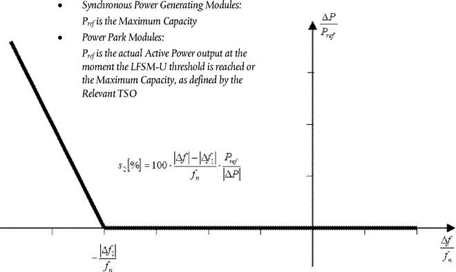
Pref is the reference active power to which ΔΡ is related and may be specified differently for synchronous power-generating modules and power park modules. ΔΡ is the change in active power output from the power-generating module. fn is the nominal frequency (50 Hz) in the network and Δf is the frequency deviation in the network. At underfrequencies where Δf is below Δf1 the power-generating module has to provide a positive active power output change according to the droop S2.
(d)in addition to point (c) of paragraph 2, the following shall apply cumulatively when frequency sensitive mode (‘FSM’) is operating:
(i)
the power-generating module shall be capable of providing active power frequency response in accordance with the parameters specified by each relevant TSO within the ranges shown in Table 4. In specifying those parameters, the relevant TSO shall take account of the following facts:
in case of overfrequency, the active power frequency response is limited by the minimum regulating level,
in case of underfrequency, the active power frequency response is limited by maximum capacity,
the actual delivery of active power frequency response depends on the operating and ambient conditions of the power-generating module when this response is triggered, in particular limitations on operation near maximum capacity at low frequencies according to paragraphs 4 and 5 of Article 13 and available primary energy sources;
Table 4
Parameters for active power frequency response in FSM (explanation for Figure 5)


Figure 5
Active power frequency response capability of power-generating modules in FSM illustrating the case of zero deadband and insensitivity

Pref is the reference active power to which ΔΡ is related. ΔΡ is the change in active power output from the power-generating module. fn is the nominal frequency (50 Hz) in the network and Δf is the frequency deviation in the network.
(ii)
the frequency response deadband of frequency deviation and droop must be able to be reselected repeatedly;
(iii)
in the event of a frequency step change, the power-generating module shall be capable of activating full active power frequency response, at or above the full line shown in Figure 6 in accordance with the parameters specified by each TSO (which shall aim at avoiding active power oscillations for the power-generating module) within the ranges given in Table 5. The combination of choice of the parameters specified by the TSO shall take possible technology-dependent limitations into account;
(iv)
the initial activation of active power frequency response required shall not be unduly delayed.
If the delay in initial activation of active power frequency response is greater than two seconds, the power-generating facility owner shall provide technical evidence demonstrating why a longer time is needed.
For power-generating modules without inertia, the relevant TSO may specify a shorter time than two seconds. If the power-generating facility owner cannot meet this requirement they shall provide technical evidence demonstrating why a longer time is needed for the initial activation of active power frequency response;
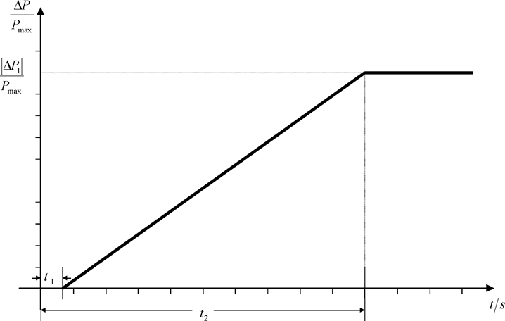
Pmax is the maximum capacity to which ΔΡ relates. ΔΡ is the change in active power output from the power-generating module. The power-generating module has to provide active power output ΔΡ up to the point ΔΡ1 in accordance with the times t1 and t2 with the values of ΔΡ1, t1and t2 being specified by the relevant TSO according to Table 5. t1 is the initial delay. t2 is the time for full activation.
(v)
the power-generating module shall be capable of providing full active power frequency response for a period of between 15 and 30 minutes as specified by the relevant TSO. In specifying the period, the TSO shall have regard to active power headroom and primary energy source of the power-generating module;
(vi)
within the time limits laid down in point (v) of paragraph 2(d), active power control must not have any adverse impact on the active power frequency response of power-generating modules;
(vii)
the parameters specified by the relevant TSO in accordance with points (i), (ii), (iii) and (v) shall be notified to the relevant regulatory authority. The modalities of that notification shall be specified in accordance with the applicable national regulatory framework;
Table 5
Parameters for full activation of active power frequency response resulting from frequency step change (explanation for Figure 6)

(e)with regard to frequency restoration control, the power-generating module shall provide functionalities complying with specifications specified by the relevant TSO, aiming at restoring frequency to its nominal value or maintaining power exchange flows between control areas at their scheduled values;
(f)with regard to disconnection due to underfrequency, power-generating facilities capable of acting as a load, including hydro pump-storage power-generating facilities, shall be capable of disconnecting their load in case of underfrequency. The requirement referred to in this point does not extend to auxiliary supply;
(g)with regard to real-time monitoring of FSM:
(i)
to monitor the operation of active power frequency response, the communication interface shall be equipped to transfer in real time and in a secured manner from the power-generating facility to the network control centre of the relevant system operator or the relevant TSO, at the request of the relevant system operator or the relevant TSO, at least the following signals:
status signal of FSM (on/off),
scheduled active power output,
actual value of the active power output,
actual parameter settings for active power frequency response,
droop and deadband;
(ii)
the relevant system operator and the relevant TSO shall specify additional signals to be provided by the power-generating facility by monitoring and recording devices in order to verify the performance of the active power frequency response provision of participating power-generating modules.
3.With regard to voltage stability, type C power-generating modules shall be capable of automatic disconnection when voltage at the connection point reaches levels specified by the relevant system operator in coordination with the relevant TSO.
The terms and settings for actual automatic disconnection of power-generating modules shall be specified by the relevant system operator in coordination with the relevant TSO.
4.Type C power-generating modules shall fulfil the following requirements relating to robustness:
(a)in the event of power oscillations, power-generating modules shall retain steady-state stability when operating at any operating point of the P-Q-capability diagram;
(b)without prejudice to paragraph 4 and 5 of Article 13, power-generating modules shall be capable of remaining connected to the network and operating without power reduction, as long as voltage and frequency remain within the specified limits pursuant to this Regulation;
(c)power-generating modules shall be capable of remaining connected to the network during single-phase or three-phase auto-reclosures on meshed network lines, if applicable to the network to which they are connected. The details of that capability shall be subject to coordination and agreements on protection schemes and settings as referred to in point (b) of Article 14(5).
5.Type C power-generating modules shall fulfil the following requirements relating to system restoration:
(a)with regard to black start capability:
(i)
black start capability is not mandatory without prejudice to the Member State's rights to introduce obligatory rules in order to ensure system security;
(ii)
power-generating facility owners shall, at the request of the relevant TSO, provide a quotation for providing black start capability. The relevant TSO may make such a request if it considers system security to be at risk due to a lack of black start capability in its control area;
(iii)
a power-generating module with black start capability shall be capable of starting from shutdown without any external electrical energy supply within a time frame specified by the relevant system operator in coordination with the relevant TSO;
(iv)
a power-generating module with black start capability shall be able to synchronise within the frequency limits laid down in point (a) of Article 13(1) and, where applicable, voltage limits specified by the relevant system operator or in Article 16(2);
(v)
a power-generating module with black start capability shall be capable of automatically regulating dips in voltage caused by connection of demand;
(vi)
a power-generating module with black start capability shall:
be capable of regulating load connections in block load,
be capable of operating in LFSM-O and LFSM-U, as specified in point (c) of paragraph 2 and Article 13(2),
control frequency in case of overfrequency and underfrequency within the whole active power output range between minimum regulating level and maximum capacity as well as at houseload level,
be capable of parallel operation of a few power-generating modules within one island, and
control voltage automatically during the system restoration phase;
(b)with regard to the capability to take part in island operation:
(i)
power-generating modules shall be capable of taking part in island operation if required by the relevant system operator in coordination with the relevant TSO and:
the frequency limits for island operation shall be those established in accordance with point (a) of Article 13(1),
the voltage limits for island operation shall be those established in accordance with Article 15(3) or Article 16(2), where applicable;
(ii)
power-generating modules shall be able to operate in FSM during island operation, as specified in point (d) of paragraph 2.
In the event of a power surplus, power-generating modules shall be capable of reducing the active power output from a previous operating point to any new operating point within the P-Q-capability diagram. In that regard, the power-generating module shall be capable of reducing active power output as much as inherently technically feasible, but to at least 55 % of its maximum capacity;
(iii)
the method for detecting a change from interconnected system operation to island operation shall be agreed between the power-generating facility owner and the relevant system operator in coordination with the relevant TSO. The agreed method of detection must not rely solely on the system operator's switchgear position signals;
(iv)
power-generating modules shall be able to operate in LFSM-O and LFSM-U during island operation, as specified in point (c) of paragraph 2 and Article 13(2);
(c)with regard to quick re-synchronisation capability:
(i)
in case of disconnection of the power-generating module from the network, the power-generating module shall be capable of quick re-synchronisation in line with the protection strategy agreed between the relevant system operator in coordination with the relevant TSO and the power-generating facility;
(ii)
a power-generating module with a minimum re-synchronisation time greater than 15 minutes after its disconnection from any external power supply must be designed to trip to houseload from any operating point in its P-Q-capability diagram. In this case, the identification of houseload operation must not be based solely on the system operator's switchgear position signals;
(iii)
power-generating modules shall be capable of continuing operation following tripping to houseload, irrespective of any auxiliary connection to the external network. The minimum operation time shall be specified by the relevant system operator in coordination with the relevant TSO, taking into consideration the specific characteristics of prime mover technology.
6.Type C power-generating modules shall fulfil the following general system management requirements:
(a)with regard to loss of angular stability or loss of control, a power-generating module shall be capable of disconnecting automatically from the network in order to help preserve system security or to prevent damage to the power-generating module. The power-generating facility owner and the relevant system operator in coordination with the relevant TSO shall agree on the criteria for detecting loss of angular stability or loss of control;
(b)with regard to instrumentation:
(i)
power-generating facilities shall be equipped with a facility to provide fault recording and monitoring of dynamic system behaviour. This facility shall record the following parameters:
voltage,
active power,
reactive power, and
frequency.
The relevant system operator shall have the right to specify quality of supply parameters to be complied with on condition that reasonable prior notice is given;
(ii)
the settings of the fault recording equipment, including triggering criteria and the sampling rates shall be agreed between the power-generating facility owner and the relevant system operator in coordination with the relevant TSO;
(iii)
the dynamic system behaviour monitoring shall include an oscillation trigger specified by the relevant system operator in coordination with the relevant TSO, with the purpose of detecting poorly damped power oscillations;
(iv)
the facilities for quality of supply and dynamic system behaviour monitoring shall include arrangements for the power-generating facility owner, and the relevant system operator and the relevant TSO to access the information. The communications protocols for recorded data shall be agreed between the power-generating facility owner, the relevant system operator and the relevant TSO;
(c)with regard to the simulation models:
(i)
at the request of the relevant system operator or the relevant TSO, the power-generating facility owner shall provide simulation models which properly reflect the behaviour of the power-generating module in both steady-state and dynamic simulations (50 Hz component) or in electromagnetic transient simulations.
The power-generating facility owner shall ensure that the models provided have been verified against the results of compliance tests referred to in Chapters 2, 3 and 4 of Title IV, and shall notify the results of the verification to the relevant system operator or relevant TSO. Member States may require that such verification be carried out by an authorised certifier;
(ii)
the models provided by the power-generating facility owner shall contain the following sub-models, depending on the existence of the individual components:
alternator and prime mover,
speed and power control,
voltage control, including, if applicable, power system stabiliser (‘PSS’) function and excitation control system,
power-generating module protection models, as agreed between the relevant system operator and the power-generating facility owner, and
converter models for power park modules;
(iii)
the request by the relevant system operator referred to in point (i) shall be coordinated with the relevant TSO. It shall include:
the format in which models are to be provided,
the provision of documentation on a model's structure and block diagrams,
an estimate of the minimum and maximum short circuit capacity at the connection point, expressed in MVA, as an equivalent of the network;
(iv)
the power-generating facility owner shall provide recordings of the power-generating module's performance to the relevant system operator or relevant TSO if requested. The relevant system operator or relevant TSO may make such a request, in order to compare the response of the models with those recordings;
(d)with regard to the installation of devices for system operation and devices for system security, if the relevant system operator or the relevant TSO considers that it is necessary to install additional devices in a power-generating facility in order to preserve or restore system operation or security, the relevant system operator or relevant TSO and the power-generating facility owner shall investigate that matter and agree on an appropriate solution;
(e)the relevant system operator shall specify, in coordination with the relevant TSO, minimum and maximum limits on rates of change of active power output (ramping limits) in both an up and down direction of change of active power output for a power-generating module, taking into consideration the specific characteristics of prime mover technology;
(f)earthing arrangement of the neutral-point at the network side of step-up transformers shall comply with the specifications of the relevant system operator.
Article 16U.K.General requirements for type D power-generating modules
1.In addition to fulfilling the requirements listed in Article 13, except for Article 13(2)(b), (6) and (7), Article 14, except for Article 14(2), and Article 15, except for Article 15(3), type D power-generating modules shall fulfil the requirements set out in this Article.
2.Type D power-generating modules shall fulfil the following requirements relating to voltage stability:
(a)with regard to voltage ranges:
(i)
without prejudice to point (a) of Article 14(3) and point (a) of paragraph 3 below, a power-generating module shall be capable of staying connected to the network and operating within the ranges of the network voltage at the connection point, expressed by the voltage at the connection point related to the reference 1 pu voltage, and for the time periods specified in Tables 6.1 and 6.2;
(ii)
the relevant TSO may specify shorter periods of time during which power-generating modules shall be capable of remaining connected to the network in the event of simultaneous overvoltage and underfrequency or simultaneous undervoltage and overfrequency;
(iii)
notwithstanding the provisions of point (i), the relevant TSO in Spain may require power-generating modules to be capable of remaining connected to the network in the voltage range between 1,05 pu and 1,0875 pu for an unlimited period;
(iv)
for the 400 kV grid voltage level (or alternatively commonly referred to as 380 kV level), the reference 1 pu value is 400 kV; for other grid voltage levels, the reference 1 pu voltage may differ for each system operator in the same synchronous area;
(v)
notwithstanding the provisions of point (i), the relevant TSOs in the Baltic synchronous area may require power-generating modules to remain connected to the 400 kV network in the voltage range limits and for the time periods that apply in the Continental Europe synchronous area;
Table 6.1
| Synchronous area | Voltage range | Time period for operation |
|---|---|---|
| Continental Europe | 0,85 pu-0,90 pu | 60 minutes |
| 0,90 pu-1,118 pu | Unlimited | |
| 1,118 pu-1,15 pu | To be specified by each TSO, but not less than 20 minutes and not more than 60 minutes | |
| Nordic | 0,90 pu-1,05 pu | Unlimited |
| 1,05 pu-1,10 pu | 60 minutes | |
| Great Britain | 0,90 pu-1,10 pu | Unlimited |
| Ireland and Northern Ireland | 0,90 pu-1,118 pu | Unlimited |
| Baltic | 0,85 pu-0,90 pu | 30 minutes |
| 0,90 pu-1,118 pu | Unlimited | |
| 1,118 pu-1,15 pu | 20 minutes |
The table shows the minimum time periods during which a power-generating module must be capable of operating for voltages deviating from the reference 1 pu value at the connection point without disconnecting from the network, where the voltage base for pu values is from 110 kV to 300 kV.
Table 6.2
| Synchronous area | Voltage range | Time period for operation |
|---|---|---|
| Continental Europe | 0,85 pu-0,90 pu | 60 minutes |
| 0,90 pu-1,05 pu | Unlimited | |
| 1,05 pu-1,10 pu | To be specified by each TSO, but not less than 20 minutes and not more than 60 minutes | |
| Nordic | 0,90 pu-1,05 pu | Unlimited |
| 1,05 pu-1,10 pu | To be specified by each TSO, but not more than 60 minutes | |
| Great Britain | 0,90 pu-1,05 pu | Unlimited |
| 1,05 pu-1,10 pu | 15 minutes | |
| Ireland and Northern Ireland | 0,90 pu-1,05 pu | Unlimited |
| Baltic | 0,88 pu-0,90 pu | 20 minutes |
| 0,90 pu-1,097 pu | Unlimited | |
| 1,097 pu-1,15 pu | 20 minutes |
The table shows the minimum time periods during which a power-generating module must be capable of operating for voltages deviating from the reference 1 pu value at the connection point without disconnecting from the network where the voltage base for pu values is from 300 kV to 400 kV.
(b)wider voltage ranges or longer minimum time periods for operation may be agreed between the relevant system operator and the power-generating facility owner in coordination with the relevant TSO. If wider voltage ranges or longer minimum times for operation are economically and technically feasible, the power-generating facility owner shall not unreasonably withhold an agreement;
(c)without prejudice to point (a), the relevant system operator in coordination with the relevant TSO shall have the right to specify voltages at the connection point at which a power-generating module is capable of automatic disconnection. The terms and settings for automatic disconnection shall be agreed between the relevant system operator and the power-generating facility owner.
3.Type D power-generating modules shall fulfil the following requirements in relation to robustness:
(a)with regard to fault-ride-through capability:
(i)
power-generating modules shall be capable of staying connected to the network and continuing to operate stably after the power system has been disturbed by secured faults. That capability shall be in accordance with a voltage-against-time profile at the connection point for fault conditions specified by the relevant TSO.
The voltage-against-time-profile shall express a lower limit of the actual course of the phase-to-phase voltages on the network voltage level at the connection point during a symmetrical fault, as a function of time before, during and after the fault.
That lower limit shall be specified by the relevant TSO, using the parameters set out in Figure 3 and within the ranges set out in Tables 7.1 and 7.2 for type D power-generating modules connected at or above the 110 kV level.
That lower limit shall also be specified by the relevant TSO, using parameters set out in Figure 3 and within the ranges set out in Tables 3.1 and 3.2 for type D power-generating modules connected below the 110 kV level;
(ii)
each TSO shall specify the pre-fault and post-fault conditions for the fault-ride-through capability referred to in point (iv) of Article 14(3)(a). The specified pre-fault and post-fault conditions for the fault-ride-through capability shall be made publicly available;
Table 7.1
Parameters for Figure 3 for fault-ride-through capability of synchronous power-generating modules
| Voltage parameters (pu) | Time parameters (seconds) | ||
|---|---|---|---|
| Uret: | 0 | tclear: | 0,14-0,15 (or 0,14-0,25 if system protection and secure operation so require) |
| Uclear: | 0,25 | trec1: | tclear-0,45 |
| Urec1: | 0,5-0,7 | trec2: | trec1-0,7 |
| Urec2: | 0,85-0,9 | trec3: | trec2-1,5 |
Table 7.2
Parameters for Figure 3 for fault-ride-through capability of power park modules
| Voltage parameters (pu) | Time parameters (seconds) | ||
|---|---|---|---|
| Uret: | 0 | tclear: | 0,14-0,15 (or 0,14-0,25 if system protection and secure operation so require) |
| Uclear: | Uret | trec1: | tclear |
| Urec1: | Uclear | trec2: | trec1 |
| Urec2: | 0,85 | trec3: | 1,5-3,0 |
(b)at the request of a power-generating facility owner, the relevant system operator shall provide the pre-fault and post-fault conditions to be considered for fault-ride-through capability as an outcome of the calculations at the connection point as specified in point (iv) of Article 14(3)(a) regarding:
(i)
pre-fault minimum short circuit capacity at each connection point expressed in MVA;
(ii)
pre-fault operating point of the power-generating module expressed as active power output and reactive power output at the connection point and voltage at the connection point; and
(iii)
post-fault minimum short circuit capacity at each connection point expressed in MVA;
(c)fault-ride-through capabilities in case of asymmetrical faults shall be specified by each TSO.
4.Type D power-generating modules shall fulfil the following general system management requirements:
(a)with regard to synchronisation, when starting a power-generating module, synchronisation shall be performed by the power-generating facility owner only after authorisation by the relevant system operator;
(b)the power-generating module shall be equipped with the necessary synchronisation facilities;
(c)synchronisation of power-generating modules shall be possible at frequencies within the ranges set out in Table 2;
(d)the relevant system operator and the power-generating facility owner shall agree on the settings of synchronisation devices to be concluded prior to operation of the power-generating module. This agreement shall cover:
(i)
voltage;
(ii)
frequency;
(iii)
phase angle range;
(iv)
phase sequence;
(v)
deviation of voltage and frequency.
CHAPTER 2 U.K. Requirements for synchronous power-generating modules
Article 17U.K.Requirements for type B synchronous power-generating modules
1.Type B synchronous power-generating modules shall fulfil the requirements listed in Articles 13, except for Article 13(2)(b), and 14.
2.Type B synchronous power-generating modules shall fulfil the following additional requirements relating to voltage stability:
(a)with regard to reactive power capability, the relevant system operator shall have the right to specify the capability of a synchronous power-generating module to provide reactive power;
(b)with regard to the voltage control system, a synchronous power-generating module shall be equipped with a permanent automatic excitation control system that can provide constant alternator terminal voltage at a selectable setpoint without instability over the entire operating range of the synchronous power-generating module.
3.With regard to robustness, type B synchronous power-generating modules shall be capable of providing post-fault active power recovery. The relevant TSO shall specify the magnitude and time for active power recovery.
Article 18U.K.Requirements for type C synchronous power-generating modules
1.Type C synchronous power-generating modules shall fulfil the requirements laid down in Articles 13, 14, 15 and 17, except for Article 13(2)(b) and 13(6), Article 14(2) and Article 17(2)(a).
2.Type C synchronous power-generating modules shall fulfil the following additional requirements in relation to voltage stability:
(a)with regard to reactive power capability, the relevant system operator may specify supplementary reactive power to be provided if the connection point of a synchronous power-generating module is neither located at the high-voltage terminals of the step-up transformer to the voltage level of the connection point nor at the alternator terminals, if no step-up transformer exists. This supplementary reactive power shall compensate the reactive power demand of the high-voltage line or cable between the high-voltage terminals of the step-up transformer of the synchronous power-generating module or its alternator terminals, if no step-up transformer exists, and the connection point and shall be provided by the responsible owner of that line or cable;
(b)with regard to reactive power capability at maximum capacity:
(i)
the relevant system operator in coordination with the relevant TSO shall specify the reactive power provision capability requirements in the context of varying voltage. For that purpose the relevant system operator shall specify a U-Q/Pmax-profile within the boundaries of which the synchronous power-generating module shall be capable of providing reactive power at its maximum capacity. The specified U-Q/Pmax profile may take any shape, having regard to the potential costs of delivering the capability to provide reactive power production at high voltages and reactive power consumption at low voltages;
(ii)
the U-Q/Pmax-profile shall be specified by the relevant system operator in coordination with the relevant TSO, in conformity with the following principles:
the U-Q/Pmax-profile shall not exceed the U-Q/Pmax-profile envelope, represented by the inner envelope in Figure 7,
the dimensions of the U-Q/Pmax-profile envelope (Q/Pmax range and voltage range) shall be within the range specified for each synchronous area in Table 8, and
the position of the U-Q/Pmax-profile envelope shall be within the limits of the fixed outer envelope in Figure 7;
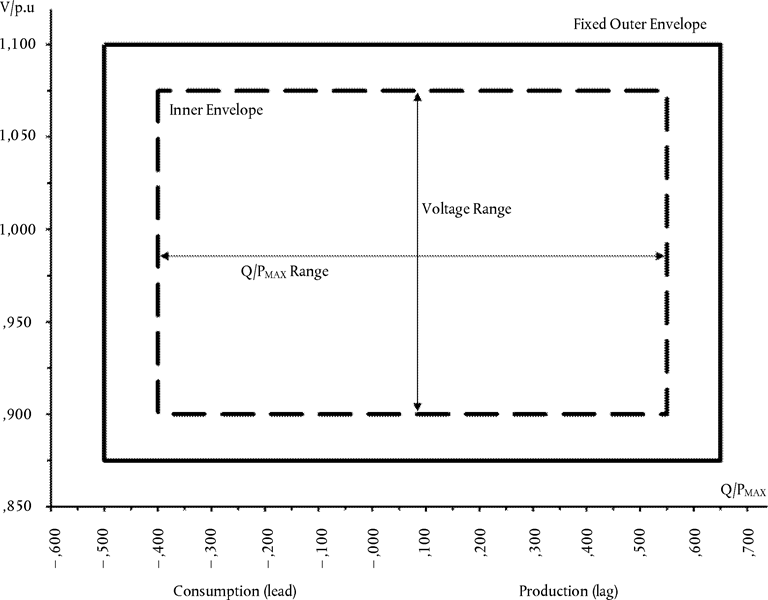
The diagram represents boundaries of a U-Q/Pmax-profile by the voltage at the connection point, expressed by the ratio of its actual value and the reference 1 pu value, against the ratio of the reactive power (Q) and the maximum capacity (Pmax). The position, size and shape of the inner envelope are indicative.
Table 8
Parameters for the inner envelope in Figure 7
| Synchronous area | Maximum range of Q/Pmax | Maximum range of steady-state voltage level in PU |
|---|---|---|
| Continental Europe | 0,95 | 0,225 |
| Nordic | 0,95 | 0,150 |
| Great Britain | 0,95 | 0,225 |
| Ireland and Northern Ireland | 1,08 | 0,218 |
| Baltic | 1,0 | 0,220 |
(iii)
the reactive power provision capability requirement applies at the connection point. For profile shapes other than rectangular, the voltage range represents the highest and lowest values. The full reactive power range is therefore not expected to be available across the range of steady-state voltages;
(iv)
the synchronous power-generating module shall be capable of moving to any operating point within its U-Q/Pmax profile in appropriate timescales to target values requested by the relevant system operator;
(c)with regard to reactive power capability below maximum capacity, when operating at an active power output below the maximum capacity (P < Pmax), the synchronous power-generating modules shall be capable of operating at every possible operating point in the P-Q-capability diagram of the alternator of that synchronous power-generating module, at least down to minimum stable operating level. Even at reduced active power output, reactive power supply at the connection point shall correspond fully to the P-Q-capability diagram of the alternator of that synchronous power-generating module, taking the auxiliary supply power and the active and reactive power losses of the step-up transformer, if applicable, into account.
Article 19U.K.Requirements for type D synchronous power-generating modules
1.Type D synchronous power-generating modules shall fulfil the requirements laid down in Article 13, except for Article 13(2)(b), (6) and (7), Article 14 except for Article 14(2), Article 15, except for Article 15(3), Article 16, Article 17, except for Article 17(2) and Article 18.
2.Type D synchronous power-generating modules shall fulfil the following additional requirements in relation to voltage stability:
(a)the parameters and settings of the components of the voltage control system shall be agreed between the power-generating facility owner and the relevant system operator, in coordination with the relevant TSO;
(b)the agreement referred to in subparagraph (a) shall cover the specifications and performance of an automatic voltage regulator (‘AVR’) with regard to steady-state voltage and transient voltage control and the specifications and performance of the excitation control system. The latter shall include:
(i)
bandwidth limitation of the output signal to ensure that the highest frequency of response cannot excite torsional oscillations on other power-generating modules connected to the network;
(ii)
an underexcitation limiter to prevent the AVR from reducing the alternator excitation to a level which would endanger synchronous stability;
(iii)
an overexcitation limiter to ensure that the alternator excitation is not limited to less than the maximum value that can be achieved whilst ensuring that the synchronous power-generating module is operating within its design limits;
(iv)
a stator current limiter; and
(v)
a PSS function to attenuate power oscillations, if the synchronous power-generating module size is above a value of maximum capacity specified by the relevant TSO.
3.The relevant TSO and the power-generating facility owner shall enter into an agreement regarding technical capabilities of the power-generating module to aid angular stability under fault conditions.
CHAPTER 3 U.K. Requirements for power park modules
Article 20U.K.Requirements for type B power park modules
1.Type B power park modules shall fulfil the requirements laid down in Articles 13, except for Article 13(2)(b), and Article 14.
2.Type B power park modules shall fulfil the following additional requirements in relation to voltage stability:
(a)with regard to reactive power capability, the relevant system operator shall have the right to specify the capability of a power park module to provide reactive power;
(b)the relevant system operator in coordination with the relevant TSO shall have the right to specify that a power park module be capable of providing fast fault current at the connection point in case of symmetrical (3-phase) faults, under the following conditions:
(i)
the power park module shall be capable of activating the supply of fast fault current either by:
ensuring the supply of the fast fault current at the connection point, or
measuring voltage deviations at the terminals of the individual units of the power park module and providing a fast fault current at the terminals of these units;
(ii)
the relevant system operator in coordination with the relevant TSO shall specify:
how and when a voltage deviation is to be determined as well as the end of the voltage deviation,
the characteristics of the fast fault current, including the time domain for measuring the voltage deviation and fast fault current, for which current and voltage may be measured differently from the method specified in Article 2,
the timing and accuracy of the fast fault current, which may include several stages during a fault and after its clearance;
(c)with regard to the supply of fast fault current in case of asymmetrical (1-phase or 2-phase) faults, the relevant system operator in coordination with the relevant TSO shall have the right to specify a requirement for asymmetrical current injection.
3.Type B power park modules shall fulfil the following additional requirements in relation to robustness:
(a)the relevant TSO shall specify the post-fault active power recovery that the power park module is capable of providing and shall specify:
(i)
when the post-fault active power recovery begins, based on a voltage criterion;
(ii)
a maximum allowed time for active power recovery; and
(iii)
a magnitude and accuracy for active power recovery;
(b)the specifications shall be in accordance with the following principles:
(i)
interdependency between fast fault current requirements according to points (b) and (c) of paragraph 2 and active power recovery;
(ii)
dependence between active power recovery times and duration of voltage deviations;
(iii)
a specified limit of the maximum allowed time for active power recovery;
(iv)
adequacy between the level of voltage recovery and the minimum magnitude for active power recovery; and
(v)
adequate damping of active power oscillations.
Article 21U.K.Requirements for type C power park modules
1.Type C power park modules shall fulfil the requirements listed in Articles 13, except for Article 13(2)(b) and (6), Article 14, except for Article 14(2), Article 15 and Article 20, except for Article 20(2)(a), unless referred to otherwise in point (v) of paragraph 3(d).
2.Type C power park modules shall fulfil the following additional requirements in relation to frequency stability:
(a)the relevant TSO shall have the right to specify that power park modules be capable of providing synthetic inertia during very fast frequency deviations;
(b)the operating principle of control systems installed to provide synthetic inertia and the associated performance parameters shall be specified by the relevant TSO.
3.Type C power park modules shall fulfil the following additional requirements in relation to voltage stability:
(a)with regard to reactive power capability, the relevant system operator may specify supplementary reactive power to be provided if the connection point of a power park module is neither located at the high-voltage terminals of the step-up transformer to the voltage level of the connection point nor at the convertor terminals, if no step-up transformer exists. This supplementary reactive power shall compensate the reactive power demand of the high-voltage line or cable between the high-voltage terminals of the step-up transformer of the power park module or its convertor terminals, if no step-up transformer exists, and the connection point and shall be provided by the responsible owner of that line or cable.
(b)with regard to reactive power capability at maximum capacity:
(i)
the relevant system operator in coordination with the relevant TSO shall specify the reactive power provision capability requirements in the context of varying voltage. To that end, it shall specify a U-Q/Pmax-profile that may take any shape within the boundaries of which the power park module shall be capable of providing reactive power at its maximum capacity;
(ii)
the U-Q/Pmax-profile shall be specified by each relevant system operator in coordination with the relevant TSO in conformity with the following principles:
the U-Q/Pmax-profile shall not exceed the U-Q/Pmax-profile envelope, represented by the inner envelope in Figure 8,
the dimensions of the U-Q/Pmax-profile envelope (Q/Pmax range and voltage range) shall be within the values specified for each synchronous area in Table 9,
the position of the U-Q/Pmax-profile envelope shall be within the limits of the fixed outer envelope set out in Figure 8, and
the specified U-Q/Pmax profile may take any shape, having regard to the potential costs of delivering the capability to provide reactive power production at high voltages and reactive power consumption at low voltages;
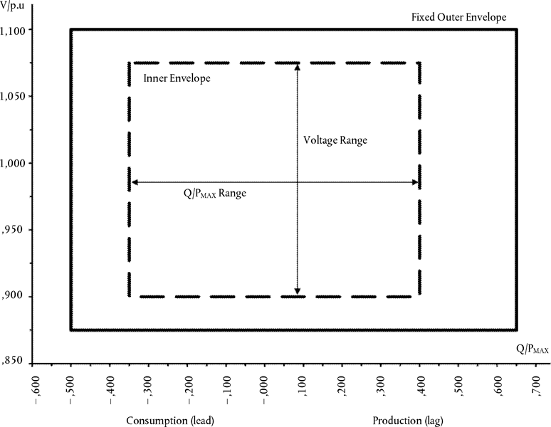
The diagram represents boundaries of a U-Q/Pmax-profile by the voltage at the connection point, expressed by the ratio of its actual value and its reference 1 pu value, against the ratio of the reactive power (Q) and the maximum capacity (Pmax). The position, size and shape of the inner envelope are indicative.
Table 9
Parameters for the inner envelope in Figure 8
| Synchronous area | Maximum range of Q/Pmax | Maximum range of steady-state voltage level in PU |
|---|---|---|
| Continental Europe | 0,75 | 0,225 |
| Nordic | 0,95 | 0,150 |
| Great Britain | 0,66 | 0,225 |
| Ireland and Northern Ireland | 0,66 | 0,218 |
| Baltic | 0,80 | 0,220 |
(iii)
the reactive power provision capability requirement applies at the connection point. For profile shapes other than rectangular, the voltage range represents the highest and lowest values. The full reactive power range is therefore not expected to be available across the range of steady-state voltages;
(c)with regard to reactive power capability below maximum capacity:
(i)
the relevant system operator in coordination with the relevant TSO shall specify the reactive power provision capability requirements and shall specify a P-Q/Pmax-profile that may take any shape within the boundaries of which the power park module shall be capable of providing reactive power below maximum capacity;
(ii)
the P-Q/Pmax-profile shall be specified by each relevant system operator in coordination with the relevant TSO, in conformity with the following principles:
the P-Q/Pmax-profile shall not exceed the P-Q/Pmax-profile envelope, represented by the inner envelope in Figure 9,
the Q/Pmax range of the P-Q/Pmax-profile envelope is specified for each synchronous area in Table 9,
the active power range of the P-Q/Pmax-profile envelope at zero reactive power shall be 1 pu,
the P-Q/Pmax-profile can be of any shape and shall include conditions for reactive power capability at zero active power, and
the position of the P-Q/Pmax-profile envelope shall be within the limits of the fixed outer envelope set out in Figure 9;
(iii)
when operating at an active power output below maximum capacity (P<Pmax), the power park module shall be capable of providing reactive power at any operating point inside its P-Q/Pmax-profile, if all units of that power park module which generate power are technically available that is to say they are not out of service due to maintenance or failure, otherwise there may be less reactive power capability, taking into consideration the technical availabilities;

The diagram represents boundaries of a P-Q/Pmax-profile at the connection point by the active power, expressed by the ratio of its actual value and the maximum capacity pu, against the ratio of the reactive power (Q) and the maximum capacity (Pmax). The position, size and shape of the inner envelope are indicative.
(iv)
the power park module shall be capable of moving to any operating point within its P-Q/Pmax profile in appropriate timescales to target values requested by the relevant system operator;
(d)with regard to reactive power control modes:
(i)
the power park module shall be capable of providing reactive power automatically by either voltage control mode, reactive power control mode or power factor control mode;
(ii)
for the purposes of voltage control mode, the power park module shall be capable of contributing to voltage control at the connection point by provision of reactive power exchange with the network with a setpoint voltage covering 0,95 to 1,05 pu in steps no greater than 0,01 pu, with a slope having a range of at least 2 to 7 % in steps no greater than 0,5 %. The reactive power output shall be zero when the grid voltage value at the connection point equals the voltage setpoint;
(iii)
the setpoint may be operated with or without a deadband selectable in a range from zero to ± 5 % of reference 1 pu network voltage in steps no greater than 0,5 %;
(iv)
following a step change in voltage, the power park module shall be capable of achieving 90 % of the change in reactive power output within a time t1 to be specified by the relevant system operator in the range of 1 to 5 seconds, and must settle at the value specified by the slope within a time t2 to be specified by the relevant system operator in the range of 5 to 60 seconds, with a steady-state reactive tolerance no greater than 5 % of the maximum reactive power. The relevant system operator shall specify the time specifications;
(v)
for the purpose of reactive power control mode, the power park module shall be capable of setting the reactive power setpoint anywhere in the reactive power range, specified by point (a) of Article 20(2) and by points (a) and (b) of Article 21(3), with setting steps no greater than 5 MVAr or 5 % (whichever is smaller) of full reactive power, controlling the reactive power at the connection point to an accuracy within plus or minus 5 MVAr or plus or minus 5 % (whichever is smaller) of the full reactive power;
(vi)
for the purpose of power factor control mode, the power park module shall be capable of controlling the power factor at the connection point within the required reactive power range, specified by the relevant system operator according to point (a) of Article 20(2) or specified by points (a) and (b) of Article 21(3), with a target power factor in steps no greater than 0,01. The relevant system operator shall specify the target power factor value, its tolerance and the period of time to achieve the target power factor following a sudden change of active power output. The tolerance of the target power factor shall be expressed through the tolerance of its corresponding reactive power. This reactive power tolerance shall be expressed by either an absolute value or by a percentage of the maximum reactive power of the power park module;
(vii)
the relevant system operator, in coordination with the relevant TSO and with the power park module owner, shall specify which of the above three reactive power control mode options and associated setpoints is to apply, and what further equipment is needed to make the adjustment of the relevant setpoint operable remotely;
(e)with regard to prioritising active or reactive power contribution, the relevant TSO shall specify whether active power contribution or reactive power contribution has priority during faults for which fault-ride-through capability is required. If priority is given to active power contribution, this provision has to be established no later than 150 ms from the fault inception;
(f)with regard to power oscillations damping control, if specified by the relevant TSO a power park module shall be capable of contributing to damping power oscillations. The voltage and reactive power control characteristics of power park modules must not adversely affect the damping of power oscillations.
Article 22U.K.Requirements for type D power park modules
Type D power park modules shall fulfil the requirements listed in Articles 13, except for Article 13(2)(b), (6) and (7), Article 14, except for Article 14(2), Article 15, except for Article 15(3), Article 16, Article 20 except for Article 20(2)(a) and Article 21.
CHAPTER 4 U.K. Requirements for offshore power park modules
Article 23U.K.General provisions
1.The requirements set out in this Chapter apply to the connection to the network of AC-connected power park modules located offshore. An AC-connected power park module located offshore which does not have an offshore connection point shall be considered as an onshore power park module and thus shall comply with the requirements governing power park modules situated onshore.
2.The offshore connection point of an AC-connected offshore power park module shall be specified by the relevant system operator.
3.AC-connected offshore power park modules within the scope of this Regulation shall be categorised in accordance with the following offshore grid connection system configurations:
(a)configuration 1: AC connection to a single onshore grid interconnection point whereby one or more offshore power park modules that are interconnected offshore to form an offshore AC system are connected to the onshore system;
(b)configuration 2: meshed AC connections whereby a number of offshore power park modules are interconnected offshore to form an offshore AC system and the offshore AC system is connected to the onshore system at two or more onshore grid interconnection points.
Article 24U.K.Frequency stability requirements applicable to AC-connected offshore power park modules
The frequency stability requirements laid down respectively in Article 13(1) to (5), except for Article 13(2)(b), Article 15(2) and Article 21(2) shall apply to any AC-connected offshore power park module.
Article 25U.K.Voltage stability requirements applicable to AC-connected offshore power park modules
1.Without prejudice to point (a) of Article 14(3) and point (a) of Article 16(3), an AC-connected offshore power park module shall be capable of staying connected to the network and operating within the ranges of the network voltage at the connection point, expressed by the voltage at the connection point related to reference 1 pu voltage, and for the time periods specified in Table 10.
2.Notwithstanding the provisions of paragraph 1, the relevant TSO in Spain may require AC-connected offshore power park modules to remain connected to the network in the voltage range between 1,05 pu and 1,0875 pu for an unlimited period.
3.Notwithstanding the provisions of paragraph 1, the relevant TSOs in the Baltic synchronous area may require AC-connected offshore power park modules to remain connected to the 400 kV network in the voltage range and for the time periods that apply to the Continental Europe synchronous area.
Table 10
| a The voltage base for pu values is below 300 kV. | ||
| b The voltage base for pu values is from 300 kV to 400 kV. | ||
| Synchronous area | Voltage range | Time period for operation |
|---|---|---|
| Continental Europe | 0,85 pu-0,90 pu | 60 minutes |
| 0,9 pu-1,118 pua | Unlimited | |
| 1,118 pu-1,15 pua | To be specified by each TSO, but not less than 20 minutes and not more than 60 minutes | |
| 0,90 pu-1,05 pub | Unlimited | |
| 1,05 pu-1,10 pub | To be specified by each TSO, but not less than 20 minutes and not more than 60 minutes | |
| Nordic | 0,90 pu-1,05 pu | Unlimited |
| 1,05 pu-1,10 pua | 60 minutes | |
| 1,05 pu-1,10 pub | To be specified by each TSO, but not more than 60 minutes | |
| Great Britain | 0,90 pu-1,10 pua | Unlimited |
| 0,90 pu-1,05 pub | Unlimited | |
| 1,05 pu-1,10 pub | 15 minutes | |
| Ireland and Northern Ireland | 0,90 pu-1,10 pu | Unlimited |
| Baltic | 0,85 pu-0,90 pua | 30 minutes |
| 0,90 pu-1,118 pua | Unlimited | |
| 1,118 pu-1,15 pua | 20 minutes | |
| 0,88 pu-0,90 pub | 20 minutes | |
| 0,90 pu-1,097 pub | Unlimited | |
| 1,097 pu-1,15 pub | 20 minutes | |
The table shows the minimum period during which an AC-connected offshore power park module must be capable of operating over different voltage ranges deviating from the reference 1 pu value without disconnecting.
4.The voltage stability requirements specified respectively in points (b) and (c) of Article 20(2) as well as in Article 21(3) shall apply to any AC-connected offshore power park module.
5.The reactive power capability at maximum capacity specified in point (b) of Article 21(3) shall apply to AC-connected offshore power park modules, except for Table 9. Instead, the requirements of Table 11 shall apply.
Table 11
Parameters for Figure 8
| a At the offshore connection point for configuration 1. | ||
| b At the offshore connection point for configuration 2. | ||
| Synchronous area | Maximum range of Q/Pmax | Maximum range of steady-state voltage level in PU |
|---|---|---|
| Continental Europe | 0,75 | 0,225 |
| Nordic | 0,95 | 0,150 |
| Great Britain | 0a 0,33b | 0,225 |
| Ireland and Northern Ireland | 0,66 | 0,218 |
| Baltic | 0,8 | 0,22 |
Article 26U.K.Robustness requirements applicable to AC-connected offshore power park modules
1.The robustness requirements of power-generating modules laid down in Article 15(4) and Article 20(3) shall apply to AC-connected offshore power park modules.
2.The fault-ride-through capability requirements laid down in point (a) of Article 14(3) and point (a) of Article 16(3) shall apply to AC-connected offshore power park modules.
Article 27U.K.System restoration requirements applicable to AC-connected offshore power park modules
The system restoration requirements laid down respectively in Article 14(4) and Article 15(5) shall apply to AC-connected offshore power park modules.
Article 28U.K.General system management requirements applicable to AC-connected offshore power park modules
The general system management requirements laid down in Article 14(5), Article 15(6) and Article 16(4) shall apply to AC-connected offshore power park modules.
Options/Help
Print Options
PrintThe Whole Regulation
PrintThis Title only
Legislation is available in different versions:
Latest Available (revised):The latest available updated version of the legislation incorporating changes made by subsequent legislation and applied by our editorial team. Changes we have not yet applied to the text, can be found in the ‘Changes to Legislation’ area.
Original (As adopted by EU): The original version of the legislation as it stood when it was first adopted in the EU. No changes have been applied to the text.
Point in Time: This becomes available after navigating to view revised legislation as it stood at a certain point in time via Advanced Features > Show Timeline of Changes or via a point in time advanced search.
See additional information alongside the content
Geographical Extent: Indicates the geographical area that this provision applies to. For further information see ‘Frequently Asked Questions’.
Show Timeline of Changes: See how this legislation has or could change over time. Turning this feature on will show extra navigation options to go to these specific points in time. Return to the latest available version by using the controls above in the What Version box.
Opening Options
Different options to open legislation in order to view more content on screen at once
More Resources
Access essential accompanying documents and information for this legislation item from this tab. Dependent on the legislation item being viewed this may include:
- the original print PDF of the as adopted version that was used for the EU Official Journal
- lists of changes made by and/or affecting this legislation item
- all formats of all associated documents
- correction slips
- links to related legislation and further information resources
Timeline of Changes
This timeline shows the different versions taken from EUR-Lex before exit day and during the implementation period as well as any subsequent versions created after the implementation period as a result of changes made by UK legislation.
The dates for the EU versions are taken from the document dates on EUR-Lex and may not always coincide with when the changes came into force for the document.
For any versions created after the implementation period as a result of changes made by UK legislation the date will coincide with the earliest date on which the change (e.g an insertion, a repeal or a substitution) that was applied came into force. For further information see our guide to revised legislation on Understanding Legislation.
More Resources
Use this menu to access essential accompanying documents and information for this legislation item. Dependent on the legislation item being viewed this may include:
- the original print PDF of the as adopted version that was used for the print copy
- correction slips
Click 'View More' or select 'More Resources' tab for additional information including:
- lists of changes made by and/or affecting this legislation item
- confers power and blanket amendment details
- all formats of all associated documents
- links to related legislation and further information resources
 All content is available under the Open Government Licence v3.0 except where otherwise stated. This site additionally contains content derived from EUR-Lex, reused under the terms of the Commission Decision 2011/833/EU on the reuse of documents from the EU institutions. For more information see the EUR-Lex public statement on re-use.