CHAPTER 2Requirements for synchronous power-generating modules
Article 17Requirements for type B synchronous power-generating modules
1.
Type B synchronous power-generating modules shall fulfil the requirements listed in Articles 13, except for Article 13(2)(b), and 14.
2.
Type B synchronous power-generating modules shall fulfil the following additional requirements relating to voltage stability:
(a)
with regard to reactive power capability, the relevant system operator shall have the right to specify the capability of a synchronous power-generating module to provide reactive power;
(b)
with regard to the voltage control system, a synchronous power-generating module shall be equipped with a permanent automatic excitation control system that can provide constant alternator terminal voltage at a selectable setpoint without instability over the entire operating range of the synchronous power-generating module.
3.
With regard to robustness, type B synchronous power-generating modules shall be capable of providing post-fault active power recovery. The relevant TSO shall specify the magnitude and time for active power recovery.
Article 18Requirements for type C synchronous power-generating modules
1.
Type C synchronous power-generating modules shall fulfil the requirements laid down in Articles 13, 14, 15 and 17, except for Article 13(2)(b) and 13(6), Article 14(2) and Article 17(2)(a).
2.
Type C synchronous power-generating modules shall fulfil the following additional requirements in relation to voltage stability:
(a)
with regard to reactive power capability, the relevant system operator may specify supplementary reactive power to be provided if the connection point of a synchronous power-generating module is neither located at the high-voltage terminals of the step-up transformer to the voltage level of the connection point nor at the alternator terminals, if no step-up transformer exists. This supplementary reactive power shall compensate the reactive power demand of the high-voltage line or cable between the high-voltage terminals of the step-up transformer of the synchronous power-generating module or its alternator terminals, if no step-up transformer exists, and the connection point and shall be provided by the responsible owner of that line or cable;
(b)
with regard to reactive power capability at maximum capacity:
(i)
the relevant system operator in coordination with the relevant TSO shall specify the reactive power provision capability requirements in the context of varying voltage. For that purpose the relevant system operator shall specify a U-Q/Pmax-profile within the boundaries of which the synchronous power-generating module shall be capable of providing reactive power at its maximum capacity. The specified U-Q/Pmax profile may take any shape, having regard to the potential costs of delivering the capability to provide reactive power production at high voltages and reactive power consumption at low voltages;
(ii)
the U-Q/Pmax-profile shall be specified by the relevant system operator in coordination with the relevant TSO, in conformity with the following principles:
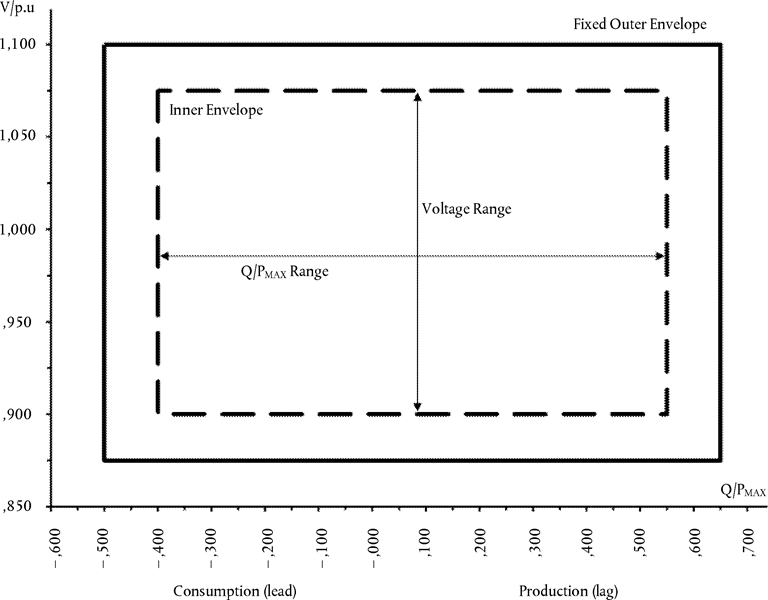
the U-Q/Pmax-profile shall not exceed the U-Q/Pmax-profile envelope, represented by the inner envelope in Figure 7,
the dimensions of the U-Q/Pmax-profile envelope (Q/Pmax range and voltage range) shall be within the range specified for each synchronous area in Table 8, and
the position of the U-Q/Pmax-profile envelope shall be within the limits of the fixed outer envelope in Figure 7;
Figure 7F1U-Q/Pmax-profile of a synchronous power-generating module
The diagram represents boundaries of a U-Q/Pmax-profile by the voltage at the connection point, expressed by the ratio of its actual value and the reference 1 pu value, against the ratio of the reactive power (Q) and the maximum capacity (Pmax). The position, size and shape of the inner envelope are indicative.
Table 8Parameters for the inner envelope in Figure 7
the reactive power provision capability requirement applies at the connection point. For profile shapes other than rectangular, the voltage range represents the highest and lowest values. The full reactive power range is therefore not expected to be available across the range of steady-state voltages;
(iv)
the synchronous power-generating module shall be capable of moving to any operating point within its U-Q/Pmax profile in appropriate timescales to target values requested by the relevant system operator;
(c)
with regard to reactive power capability below maximum capacity, when operating at an active power output below the maximum capacity (P < Pmax), the synchronous power-generating modules shall be capable of operating at every possible operating point in the P-Q-capability diagram of the alternator of that synchronous power-generating module, at least down to minimum stable operating level. Even at reduced active power output, reactive power supply at the connection point shall correspond fully to the P-Q-capability diagram of the alternator of that synchronous power-generating module, taking the auxiliary supply power and the active and reactive power losses of the step-up transformer, if applicable, into account.
Article 19Requirements for type D synchronous power-generating modules
1.
Type D synchronous power-generating modules shall fulfil the requirements laid down in Article 13, except for Article 13(2)(b), (6) and (7), Article 14 except for Article 14(2), Article 15, except for Article 15(3), Article 16, Article 17, except for Article 17(2) and Article 18.
2.
Type D synchronous power-generating modules shall fulfil the following additional requirements in relation to voltage stability:
(a)
the parameters and settings of the components of the voltage control system shall be agreed between the power-generating facility owner and the relevant system operator, in coordination with the relevant TSO;
(b)
the agreement referred to in subparagraph (a) shall cover the specifications and performance of an automatic voltage regulator (‘AVR’) with regard to steady-state voltage and transient voltage control and the specifications and performance of the excitation control system. The latter shall include:
(i)
bandwidth limitation of the output signal to ensure that the highest frequency of response cannot excite torsional oscillations on other power-generating modules connected to the network;
(ii)
an underexcitation limiter to prevent the AVR from reducing the alternator excitation to a level which would endanger synchronous stability;
(iii)
an overexcitation limiter to ensure that the alternator excitation is not limited to less than the maximum value that can be achieved whilst ensuring that the synchronous power-generating module is operating within its design limits;
(iv)
a stator current limiter; and
(v)
a PSS function to attenuate power oscillations, if the synchronous power-generating module size is above a value of maximum capacity specified by the relevant TSO.
3.
The relevant TSO and the power-generating facility owner shall enter into an agreement regarding technical capabilities of the power-generating module to aid angular stability under fault conditions.