- Latest available (Revised)
- Point in Time (31/01/2020)
- Original (As adopted by EU)
Commission Regulation (EU) 2016/631Show full title
Commission Regulation (EU) 2016/631 of 14 April 2016 establishing a network code on requirements for grid connection of generators (Text with EEA relevance)
You are here:

What Version
Advanced Features
- Show Geographical Extent(e.g. England, Wales, Scotland and Northern Ireland)
- Show Timeline of Changes
Opening Options
More Resources
Legislation originating from the EU
When the UK left the EU, legislation.gov.uk published EU legislation that had been published by the EU up to IP completion day (31 December 2020 11.00 p.m.). On legislation.gov.uk, these items of legislation are kept up-to-date with any amendments made by the UK since then.


This item of legislation originated from the EU
Legislation.gov.uk publishes the UK version. EUR-Lex publishes the EU version. The EU Exit Web Archive holds a snapshot of EUR-Lex’s version from IP completion day (31 December 2020 11.00 p.m.).
Changes over time for: CHAPTER 3
Version Superseded: 31/12/2020
Alternative versions:
Status:
Point in time view as at 31/01/2020.
Changes to legislation:
There are currently no known outstanding effects by UK legislation for Commission Regulation (EU) 2016/631,
CHAPTER 3
.
Changes to Legislation
Revised legislation carried on this site may not be fully up to date. At the current time any known changes or effects made by subsequent legislation have been applied to the text of the legislation you are viewing by the editorial team. Please see ‘Frequently Asked Questions’ for details regarding the timescales for which new effects are identified and recorded on this site.
CHAPTER 3 U.K. Requirements for power park modules
Article 20U.K.Requirements for type B power park modules
1.Type B power park modules shall fulfil the requirements laid down in Articles 13, except for Article 13(2)(b), and Article 14.
2.Type B power park modules shall fulfil the following additional requirements in relation to voltage stability:
(a)with regard to reactive power capability, the relevant system operator shall have the right to specify the capability of a power park module to provide reactive power;
(b)the relevant system operator in coordination with the relevant TSO shall have the right to specify that a power park module be capable of providing fast fault current at the connection point in case of symmetrical (3-phase) faults, under the following conditions:
(i)
the power park module shall be capable of activating the supply of fast fault current either by:
ensuring the supply of the fast fault current at the connection point, or
measuring voltage deviations at the terminals of the individual units of the power park module and providing a fast fault current at the terminals of these units;
(ii)
the relevant system operator in coordination with the relevant TSO shall specify:
how and when a voltage deviation is to be determined as well as the end of the voltage deviation,
the characteristics of the fast fault current, including the time domain for measuring the voltage deviation and fast fault current, for which current and voltage may be measured differently from the method specified in Article 2,
the timing and accuracy of the fast fault current, which may include several stages during a fault and after its clearance;
(c)with regard to the supply of fast fault current in case of asymmetrical (1-phase or 2-phase) faults, the relevant system operator in coordination with the relevant TSO shall have the right to specify a requirement for asymmetrical current injection.
3.Type B power park modules shall fulfil the following additional requirements in relation to robustness:
(a)the relevant TSO shall specify the post-fault active power recovery that the power park module is capable of providing and shall specify:
(i)
when the post-fault active power recovery begins, based on a voltage criterion;
(ii)
a maximum allowed time for active power recovery; and
(iii)
a magnitude and accuracy for active power recovery;
(b)the specifications shall be in accordance with the following principles:
(i)
interdependency between fast fault current requirements according to points (b) and (c) of paragraph 2 and active power recovery;
(ii)
dependence between active power recovery times and duration of voltage deviations;
(iii)
a specified limit of the maximum allowed time for active power recovery;
(iv)
adequacy between the level of voltage recovery and the minimum magnitude for active power recovery; and
(v)
adequate damping of active power oscillations.
Article 21U.K.Requirements for type C power park modules
1.Type C power park modules shall fulfil the requirements listed in Articles 13, except for Article 13(2)(b) and (6), Article 14, except for Article 14(2), Article 15 and Article 20, except for Article 20(2)(a), unless referred to otherwise in point (v) of paragraph 3(d).
2.Type C power park modules shall fulfil the following additional requirements in relation to frequency stability:
(a)the relevant TSO shall have the right to specify that power park modules be capable of providing synthetic inertia during very fast frequency deviations;
(b)the operating principle of control systems installed to provide synthetic inertia and the associated performance parameters shall be specified by the relevant TSO.
3.Type C power park modules shall fulfil the following additional requirements in relation to voltage stability:
(a)with regard to reactive power capability, the relevant system operator may specify supplementary reactive power to be provided if the connection point of a power park module is neither located at the high-voltage terminals of the step-up transformer to the voltage level of the connection point nor at the convertor terminals, if no step-up transformer exists. This supplementary reactive power shall compensate the reactive power demand of the high-voltage line or cable between the high-voltage terminals of the step-up transformer of the power park module or its convertor terminals, if no step-up transformer exists, and the connection point and shall be provided by the responsible owner of that line or cable.
(b)with regard to reactive power capability at maximum capacity:
(i)
the relevant system operator in coordination with the relevant TSO shall specify the reactive power provision capability requirements in the context of varying voltage. To that end, it shall specify a U-Q/Pmax-profile that may take any shape within the boundaries of which the power park module shall be capable of providing reactive power at its maximum capacity;
(ii)
the U-Q/Pmax-profile shall be specified by each relevant system operator in coordination with the relevant TSO in conformity with the following principles:
the U-Q/Pmax-profile shall not exceed the U-Q/Pmax-profile envelope, represented by the inner envelope in Figure 8,
the dimensions of the U-Q/Pmax-profile envelope (Q/Pmax range and voltage range) shall be within the values specified for each synchronous area in Table 9,
the position of the U-Q/Pmax-profile envelope shall be within the limits of the fixed outer envelope set out in Figure 8, and
the specified U-Q/Pmax profile may take any shape, having regard to the potential costs of delivering the capability to provide reactive power production at high voltages and reactive power consumption at low voltages;
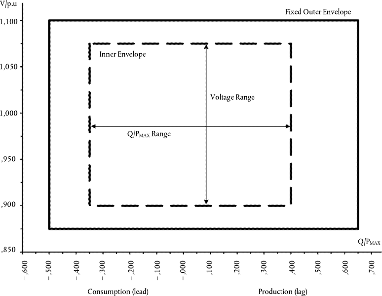
The diagram represents boundaries of a U-Q/Pmax-profile by the voltage at the connection point, expressed by the ratio of its actual value and its reference 1 pu value, against the ratio of the reactive power (Q) and the maximum capacity (Pmax). The position, size and shape of the inner envelope are indicative.
Table 9
Parameters for the inner envelope in Figure 8
| Synchronous area | Maximum range of Q/Pmax | Maximum range of steady-state voltage level in PU |
|---|---|---|
| Continental Europe | 0,75 | 0,225 |
| Nordic | 0,95 | 0,150 |
| Great Britain | 0,66 | 0,225 |
| Ireland and Northern Ireland | 0,66 | 0,218 |
| Baltic | 0,80 | 0,220 |
(iii)
the reactive power provision capability requirement applies at the connection point. For profile shapes other than rectangular, the voltage range represents the highest and lowest values. The full reactive power range is therefore not expected to be available across the range of steady-state voltages;
(c)with regard to reactive power capability below maximum capacity:
(i)
the relevant system operator in coordination with the relevant TSO shall specify the reactive power provision capability requirements and shall specify a P-Q/Pmax-profile that may take any shape within the boundaries of which the power park module shall be capable of providing reactive power below maximum capacity;
(ii)
the P-Q/Pmax-profile shall be specified by each relevant system operator in coordination with the relevant TSO, in conformity with the following principles:
the P-Q/Pmax-profile shall not exceed the P-Q/Pmax-profile envelope, represented by the inner envelope in Figure 9,
the Q/Pmax range of the P-Q/Pmax-profile envelope is specified for each synchronous area in Table 9,
the active power range of the P-Q/Pmax-profile envelope at zero reactive power shall be 1 pu,
the P-Q/Pmax-profile can be of any shape and shall include conditions for reactive power capability at zero active power, and
the position of the P-Q/Pmax-profile envelope shall be within the limits of the fixed outer envelope set out in Figure 9;
(iii)
when operating at an active power output below maximum capacity (P<Pmax), the power park module shall be capable of providing reactive power at any operating point inside its P-Q/Pmax-profile, if all units of that power park module which generate power are technically available that is to say they are not out of service due to maintenance or failure, otherwise there may be less reactive power capability, taking into consideration the technical availabilities;

The diagram represents boundaries of a P-Q/Pmax-profile at the connection point by the active power, expressed by the ratio of its actual value and the maximum capacity pu, against the ratio of the reactive power (Q) and the maximum capacity (Pmax). The position, size and shape of the inner envelope are indicative.
(iv)
the power park module shall be capable of moving to any operating point within its P-Q/Pmax profile in appropriate timescales to target values requested by the relevant system operator;
(d)with regard to reactive power control modes:
(i)
the power park module shall be capable of providing reactive power automatically by either voltage control mode, reactive power control mode or power factor control mode;
(ii)
for the purposes of voltage control mode, the power park module shall be capable of contributing to voltage control at the connection point by provision of reactive power exchange with the network with a setpoint voltage covering 0,95 to 1,05 pu in steps no greater than 0,01 pu, with a slope having a range of at least 2 to 7 % in steps no greater than 0,5 %. The reactive power output shall be zero when the grid voltage value at the connection point equals the voltage setpoint;
(iii)
the setpoint may be operated with or without a deadband selectable in a range from zero to ± 5 % of reference 1 pu network voltage in steps no greater than 0,5 %;
(iv)
following a step change in voltage, the power park module shall be capable of achieving 90 % of the change in reactive power output within a time t1 to be specified by the relevant system operator in the range of 1 to 5 seconds, and must settle at the value specified by the slope within a time t2 to be specified by the relevant system operator in the range of 5 to 60 seconds, with a steady-state reactive tolerance no greater than 5 % of the maximum reactive power. The relevant system operator shall specify the time specifications;
(v)
for the purpose of reactive power control mode, the power park module shall be capable of setting the reactive power setpoint anywhere in the reactive power range, specified by point (a) of Article 20(2) and by points (a) and (b) of Article 21(3), with setting steps no greater than 5 MVAr or 5 % (whichever is smaller) of full reactive power, controlling the reactive power at the connection point to an accuracy within plus or minus 5 MVAr or plus or minus 5 % (whichever is smaller) of the full reactive power;
(vi)
for the purpose of power factor control mode, the power park module shall be capable of controlling the power factor at the connection point within the required reactive power range, specified by the relevant system operator according to point (a) of Article 20(2) or specified by points (a) and (b) of Article 21(3), with a target power factor in steps no greater than 0,01. The relevant system operator shall specify the target power factor value, its tolerance and the period of time to achieve the target power factor following a sudden change of active power output. The tolerance of the target power factor shall be expressed through the tolerance of its corresponding reactive power. This reactive power tolerance shall be expressed by either an absolute value or by a percentage of the maximum reactive power of the power park module;
(vii)
the relevant system operator, in coordination with the relevant TSO and with the power park module owner, shall specify which of the above three reactive power control mode options and associated setpoints is to apply, and what further equipment is needed to make the adjustment of the relevant setpoint operable remotely;
(e)with regard to prioritising active or reactive power contribution, the relevant TSO shall specify whether active power contribution or reactive power contribution has priority during faults for which fault-ride-through capability is required. If priority is given to active power contribution, this provision has to be established no later than 150 ms from the fault inception;
(f)with regard to power oscillations damping control, if specified by the relevant TSO a power park module shall be capable of contributing to damping power oscillations. The voltage and reactive power control characteristics of power park modules must not adversely affect the damping of power oscillations.
Article 22U.K.Requirements for type D power park modules
Type D power park modules shall fulfil the requirements listed in Articles 13, except for Article 13(2)(b), (6) and (7), Article 14, except for Article 14(2), Article 15, except for Article 15(3), Article 16, Article 20 except for Article 20(2)(a) and Article 21.
Options/Help
Print Options
PrintThe Whole Regulation
PrintThe Whole Title
PrintThis Chapter only
Legislation is available in different versions:
Latest Available (revised):The latest available updated version of the legislation incorporating changes made by subsequent legislation and applied by our editorial team. Changes we have not yet applied to the text, can be found in the ‘Changes to Legislation’ area.
Original (As adopted by EU): The original version of the legislation as it stood when it was first adopted in the EU. No changes have been applied to the text.
Point in Time: This becomes available after navigating to view revised legislation as it stood at a certain point in time via Advanced Features > Show Timeline of Changes or via a point in time advanced search.
See additional information alongside the content
Geographical Extent: Indicates the geographical area that this provision applies to. For further information see ‘Frequently Asked Questions’.
Show Timeline of Changes: See how this legislation has or could change over time. Turning this feature on will show extra navigation options to go to these specific points in time. Return to the latest available version by using the controls above in the What Version box.
Opening Options
Different options to open legislation in order to view more content on screen at once
More Resources
Access essential accompanying documents and information for this legislation item from this tab. Dependent on the legislation item being viewed this may include:
- the original print PDF of the as adopted version that was used for the EU Official Journal
- lists of changes made by and/or affecting this legislation item
- all formats of all associated documents
- correction slips
- links to related legislation and further information resources
Timeline of Changes
This timeline shows the different versions taken from EUR-Lex before exit day and during the implementation period as well as any subsequent versions created after the implementation period as a result of changes made by UK legislation.
The dates for the EU versions are taken from the document dates on EUR-Lex and may not always coincide with when the changes came into force for the document.
For any versions created after the implementation period as a result of changes made by UK legislation the date will coincide with the earliest date on which the change (e.g an insertion, a repeal or a substitution) that was applied came into force. For further information see our guide to revised legislation on Understanding Legislation.
More Resources
Use this menu to access essential accompanying documents and information for this legislation item. Dependent on the legislation item being viewed this may include:
- the original print PDF of the as adopted version that was used for the print copy
- correction slips
Click 'View More' or select 'More Resources' tab for additional information including:
- lists of changes made by and/or affecting this legislation item
- confers power and blanket amendment details
- all formats of all associated documents
- links to related legislation and further information resources
 All content is available under the Open Government Licence v3.0 except where otherwise stated. This site additionally contains content derived from EUR-Lex, reused under the terms of the Commission Decision 2011/833/EU on the reuse of documents from the EU institutions. For more information see the EUR-Lex public statement on re-use.