- Latest available (Revised)
- Original (As adopted by EU)
Commission Regulation (EU) 2017/2400Show full title
Commission Regulation (EU) 2017/2400 of 12 December 2017 implementing Regulation (EC) No 595/2009 of the European Parliament and of the Council as regards the determination of the CO2 emissions and fuel consumption of heavy-duty vehicles and amending Directive 2007/46/EC of the European Parliament and of the Council and Commission Regulation (EU) No 582/2011 (Text with EEA relevance)
You are here:

What Version
More Resources
Revised version PDFs
- Revised 01/09/20203.68 MB
- Revised 01/03/20193.55 MB
Legislation originating from the EU
When the UK left the EU, legislation.gov.uk published EU legislation that had been published by the EU up to IP completion day (31 December 2020 11.00 p.m.). On legislation.gov.uk, these items of legislation are kept up-to-date with any amendments made by the UK since then.


This item of legislation originated from the EU
Legislation.gov.uk publishes the UK version. EUR-Lex publishes the EU version. The EU Exit Web Archive holds a snapshot of EUR-Lex’s version from IP completion day (31 December 2020 11.00 p.m.).
Status:
This is the original version as it was originally adopted in the EU.
This legislation may since have been updated - see the latest available (revised) version
ANNEX V VERIFYING ENGINE DATA
1.Introduction
The engine test procedure described in this Annex shall produce input data relating to engines for the simulation tool.
2.Definitions
For the purposes of this Annex the definitions according to UN/ECE Regulation 49 Rev.06 and, in addition to these, the following definitions shall apply:
(1)
‘engine CO2-family’ means a manufacturer's grouping of engines, as defined in paragraph 1 of Appendix 3;
(2)
‘CO2-parent engine’ means an engine selected from an engine CO2-family as specified in Appendix 3;
(3)
‘NCV’ means net calorific value of a fuel as specified in paragraph 3.2;
(4)
‘specific mass emissions’ means the total mass emissions divided by the total engine work over a defined period expressed in g/kWh;
(5)
‘specific fuel consumption’ means the total fuel consumption divided by the total engine work over a defined period expressed in g/kWh;
(6)
‘FCMC’ means fuel consumption mapping cycle;
(7)
‘Full load’ means the delivered engine torque/power at a certain engine speed when the engine is operated at maximum operator demand.
The definitions in paragraphs 3.1.5 and 3.1.6. of Annex 4 to UN/ECE Regulation 49 Rev.06 shall not apply.
3.General requirements
The calibration laboratory facilities shall comply with the requirements of either ISO/TS 16949, ISO 9000 series or ISO/IEC 17025. All laboratory reference measurement equipment, used for calibration and/or verification, shall be traceable to national or international standards.
Engines shall be grouped into engine CO2-families defined in accordance with Appendix 3. Paragraph 4.1 explains which testruns shall be performed for the purpose of certification of one specific engine CO2-family.
3.1Test conditions
All testruns performed for the purpose of certification of one specific engine CO2-family defined in accordance with Appendix 3 to this Annex shall be conducted on the same physical engine and without any changes to the setup of the engine dynamometer and the engine system, apart from the exceptions defined in paragraph 4.2 and Appendix 3.
3.1.1Laboratory test conditions
The tests shall be conducted under ambient conditions meeting the following conditions over the whole testrun:
(1)
The parameter fa describing the laboratory test conditions, determined in accordance with paragraph 6.1 of Annex 4 to UN/ECE Regulation 49 Rev.06, shall be within the following limits: 0,96 ≤ fa ≤ 1,04.
(2)
The absolute temperature (Ta) of the engine intake air expressed in Kelvin, determined in accordance with paragraph 6.1 of Annex 4 to UN/ECE Regulation 49 Rev.06 shall be within the following limits: 283 K ≤ Ta ≤ 303 K.
(3)
The atmospheric pressure expressed in kPa, determined in accordance with paragraph 6.1 of Annex 4 to UN/ECE Regulation 49 Rev.06 shall be within the following limits: 90 kPa ≤ ps ≤ 102 kPa.
If tests are performed in test cells that are able to simulate barometric conditions other than those existing in the atmosphere at the specific test site, the applicable fa value shall be determined with the simulated values of atmospheric pressure by the conditioning system. The same reference value for the simulated atmospheric pressure shall be used for the intake air and exhaust path and all other relevant engine systems. The actual value of the simulated atmospheric pressure for the intake air and exhaust path and all other relevant engine systems shall be within the limits specified in subpoint (3).
In cases where the ambient pressure in the atmosphere at the specific test site exceeds the upper limit of 102 kPa, tests in accordance with this Annex may still be performed. In this case tests shall be performed with the specific ambient air pressure in the atmosphere.
In cases where the test cell has the ability to control temperature, pressure and/or humidity of engine intake air independent of the atmospheric conditions the same settings for those parameters shall be used for all testruns performed for the purpose of certification of one specific engine CO2-family defined in accordance with Appendix 3 to this Annex.
3.1.2Engine installation
The test engine shall be installed in accordance with paragraphs 6.3 to 6.6 of Annex 4 to UN/ECE Regulation 49 Rev.06.
If auxiliaries/equipment necessary for operating the engine system are not installed as required in accordance with paragraph 6.3 of Annex 4 to UN/ECE Regulation 49 Rev.06, all measured engine torque values shall be corrected for the power required for driving these components for the purpose of this Annex in accordance with paragraph 6.3 of Annex 4 to UN/ECE Regulation 49 Rev.06.
The power consumption of the following engine components resulting in the engine torque required for driving these engine components shall be determined in accordance with Appendix 5 to this Annex:
(1)
fan
(2)
electrically powered auxiliaries/equipment necessary for operating the engine system
3.1.3Crankcase emissions
In the case of a closed crankcase, the manufacturer shall ensure that the engine's ventilation system does not permit the emission of any crankcase gases into the atmosphere. If the crankcase is of an open type, the emissions shall be measured and added to the tailpipe emissions, following the provisions set out in paragraph 6.10. of Annex 4 to UN/ECE Regulation 49 Rev.06.
3.1.4Engines with charge air-cooling
During all testruns the charge air cooling system used on the test bed shall be operated under conditions which are representative for in-vehicle application at reference ambient conditions. The reference ambient conditions are defined as 293 K for air temperature and 101,3 kPa for pressure.
The laboratory charge air cooling for tests according to this regulation should comply with the provisions specified in paragraph 6.2 of Annex 4 to UN/ECE Regulation 49 Rev.06.
3.1.5Engine cooling system
(1)
During all testruns the engine cooling system used on the test bed shall be operated under conditions which are representative for in-vehicle application at reference ambient conditions. The reference ambient conditions are defined as 293 K for air temperature and 101,3 kPa for pressure.
(2)
The engine cooling system should be equipped with thermostats according to the manufacturer specification for vehicle installation. If either a non-operational thermostat is installed or no thermostat is used, subpoint (3) shall apply. The setting of the cooling system shall be performed in accordance with subpoint (4).
(3)
If no thermostat is used or a non-operational thermostat is installed, the test bed system shall reflect the behavior of the thermostat under all test conditions. The setting of the cooling system shall be performed in accordance with subpoint (4).
(4)
The engine coolant flow rate (or alternatively the pressure differential across the engine side of the heat exchanger) and the engine coolant temperature shall be set to a value representative for in-vehicle application at reference ambient conditions when the engine is operated at rated speed and full load with the engine thermostat in fully open position. This setting defines the coolant reference temperature. For all testruns performed for the purpose of certification of one specific engine within one engine CO2-family, the cooling system setting shall not be changed, neither on the engine side nor on the test bed side of the cooling system. The temperature of the test bed side cooling medium should be kept resonably constant by good engineering judgement. The cooling medium on the test bed side of the heat exchanger shall not exceed the nominal thermostat opening temperatur downstream of the heat exchanger.
(5)
For all testruns performed for the purpose of certification of one specific engine within one engine CO2-family the engine coolant temperature shall be maintained between the nominal value of the thermostat opening temperature declared by the manufacturer and the coolant reference temperature in accordance with subpoint (4) as soon as the engine coolant has reached the declared thermostat opening temperature after engine cold start.
(6)
For the WHTC coldstart test performed in accordance with paragraph 4.3.3, the specific initial conditions are specified in paragraphs 7.6.1. and 7.6.2 of Annex 4 to UN/ECE Regulation 49 Rev.06. If simulation of the thermostat behaviour in accordance with subpoint (3) is applied, there shall be no coolant flow across the heat exchanger as long as the engine coolant has not reached the declared nominal thermostat opening temperature after cold start.
3.2Fuels
The respective reference fuel for the engine systems under test shall be selected from the fuel types listed in Table 1. The fuel properties of the reference fuels listed in Table 1 shall be those specified in Annex IX to Commission Regulation (EU) No 582/2011.
To ensure that the same fuel is used for all testruns performed for the purpose of certification of one specific engine CO2-family no refill of the tank or switch to another tank supplying the engine system shall occur. Exceptionally a refill or switch may be allowed if it can be ensured that the replacement fuel has exactly the same properties as the fuel used before (same production batch).
The NCV for the fuel used shall be determined by two separate measurements in accordance with the respective standards for each fuel type defined in Table 1. The two separate measurements shall be performed by two different labs independent from the manufacturer applying for certification. The lab performing the measurements shall comply with the requirements of ISO/IEC 17025. The approval authority shall ensure that the fuel sample used for determination of the NCV is taken from the batch of fuel used for all testruns.
If the two separate values for the NCV are deviating by more than 440 Joule per gram fuel, the values determined shall be void and the measurement campaign shall be repeated.
The mean value of the two separate NCV that are not deviating by more than 440 Joule per gram fuel shall be documented in MJ/kg rounded to 3 places to the right of the decimal point in accordance with ASTM E 29-06.
For gas fuels the standards for determining the NCV according to Table 1 contain the calculation of the calorific value based on the fuel composition. The gas fuel composition for determining the NCV shall be taken from the analysis of the reference gas fuel batch used for the certification tests. For the determination of the gas fuel composition used for determining the NCV only one single analysis by a lab independent from the manufacturer applying for certification shall be performed. For gas fuels the NCV shall be determined based on this single analysis instead of a mean value of two separate measurements.
Table 1
Reference fuels for testing
| Fuel type / engine type | Reference fuel type | Standard used for determination of NCV |
|---|---|---|
| Diesel / CI | B7 | at least ASTM D240 or DIN 59100-1 (ASTM D4809 is recommended) |
| Ethanol / CI | ED95 | at least ASTM D240 or DIN 59100-1 (ASTM D4809 is recommended) |
| Petrol / PI | E10 | at least ASTM D240 or DIN 59100-1 (ASTM D4809 is recommended) |
| Ethanol / PI | E85 | at least ASTM D240 or DIN 59100-1 (ASTM D4809 is recommended) |
| LPG / PI | LPG Fuel B | ASTM 3588 or DIN 51612 |
| Natural Gas / PI | G25 | ISO 6976 or ASTM 3588 |
3.3Lubricants
The lubricating oil for all testruns performed in accordance with this Annex shall be a commercially available oil with unrestricted manufacturer approval under normal in-service conditions as defined in paragraph 4.2 of Annex 8 to UN/ECE Regulation 49 Rev.06. Lubricants for which the usage is restricted to certain special operation conditions of the engine system or having an unusually short oil change interval shall not be used for the purpose of testruns in accordance with this Annex. The commercially available oil shall not be modified by any means and no additives shall be added.
All testruns performed for the purpose of certification of the CO2 emissions and fuel consumption related properties of one specific engine CO2-family shall be performed with the same type of lubricating oil.
3.4Fuel flow measurement system
All fuel flows consumed by the whole engine system shall be captured by the fuel flow measurement system. Additional fuel flows not directly supplied to the combustion process in the engine cylinders shall be included in the fuel flow signal for all testruns performed. Additional fuel injectors (e.g. cold start devices) not necessary for the operation of the engine system shall be disconnected from the fuel supply line during all testruns performed.
3.5Measurement equipment specifications
The measurement equipment shall meet the requirements of paragraph 9 of Annex 4 to UN/ECE Regulation 49 Rev.06.
Notwithstanding the requirements defined in paragraph 9 of Annex 4 to UN/ECE Regulation 49 Rev.06, the measurement systems listed in Table 2 shall meet the limits defined in Table 2.
Table 2
Requirements of measurement systems
| a ‘Accuracy’ means the deviation of the analyzer reading from a reference value which is traceable to a national or international standard. | ||||||
| b ‘Rise time’ means the difference in time between the 10 percent and 90 percent response of the final analyzer reading (t90 – t10). | ||||||
| c The ‘max calibration’ values shall be 1,1 times the maximum predicted value expected during all testruns for the respective measurement system. | ||||||
| Linearity | ||||||
|---|---|---|---|---|---|---|
| Measurement system | Intercept| xmin × (a1 – 1) + a0 | | Slopea1 | Standard error of estimate SEE | Coefficient of determinationr2 | Accuracya | Rise timeb |
| Engine speed | ≤ 0,2 % max calibrationc | 0,999 - 1,001 | ≤ 0,1 % max calibrationc | ≥ 0,9985 | 0,2 % of reading or 0,1 % of max. calibrationc of speed whichever is larger | ≤ 1 s |
| Engine torque | ≤ 0,5 % max calibrationc | 0,995 - 1,005 | ≤ 0,5 % max calibrationc | ≥ 0,995 | 0,6 % of reading or 0,3 % of max. calibrationc of torque whichever is larger | ≤ 1 s |
| Fuel mass flow for liquid fuels | ≤ 0,5 % max calibrationc | 0,995 - 1,005 | ≤ 0,5 % max calibrationc | ≥ 0,995 | 0,6 % of reading or 0,3 % of max. calibrationc of flow whichever is larger | ≤ 2 s |
| Fuel mass flow for gaseous fuels | ≤ 1 % max calibrationc | 0,99 - 1,01 | ≤ 1 % max calibrationc | ≥ 0,995 | 1 % of reading or 0,5 % of max. calibrationc of flow whichever is larger | ≤ 2 s |
| Electrical Power | ≤ 1 % max calibrationc | 0,98 - 1,02 | ≤ 2 % max calibrationc | ≥ 0,990 | n.a. | ≤ 1 s |
| Current | ≤ 1 % max calibrationc | 0,98 - 1,02 | ≤ 2 % max calibrationc | ≥ 0,990 | n.a. | ≤ 1 s |
| Voltage | ≤ 1 % max calibrationc | 0,98 - 1,02 | ≤ 2 % max calibrationc | ≥ 0,990 | n.a. | ≤ 1 s |
‘xmin’, used for calculation of the intercept value in Table 2, shall be 0,9 times the minimum predicted value expected during all testruns for the respective measurement system.
The signal delivery rate of the measurement systems listed in Table 2, except for the fuel mass flow measurement system, shall be at least 5 Hz (≥ 10 Hz recommended). The signal delivery rate of the fuel mass flow measurement system shall be at least 2 Hz.
All measurement data shall be recorded with a sample rate of at least 5 Hz (≥ 10 Hz recommended).
3.5.1Measurement equipment verification
A verification of the demanded requirements defined in Table 2 shall be performed for each measurement system. At least 10 reference values between xmin and the ‘max calibration’ value defined in accordance with paragraph 3.5 shall be introduced to the measurement system and the response of the measurement system shall be recorded as measured value.
For the linearity verification the measured values shall be compared to the reference values by using a least squares linear regression in accordance with paragraph A.3.2 of Appendix 3 to Annex 4 to UN/ECE Regulation 49 Rev.06.
4.Testing procedure
All measurement data shall be determined in accordance with Annex 4 to UN/ECE Regulation 49 Rev.06, unless stated otherwise in this Annex.
4.1Overview of testruns to be performed
Table 3 gives an overview of all testruns to be performed for the purpose of certification of one specific engine CO2-family defined in accordance with Appendix 3.
The fuel consumption mapping cycle in accordance with paragraph 4.3.5 and the recording of the engine motoring curve in accordance with paragraph 4.3.2 shall be omitted for all other engines except the CO2-parent engine of the engine CO2-family.
In the case that upon request of the manufacturer the provisions defined in Article 15(5) of this Regulation are applied, the fuel consumption mapping cycle in accordance with paragraph 4.3.5 and the recording of the engine motoring curve in accordance with paragraph 4.3.2 shall be performed additionally for that specific engine.
Table 3
Overview of testruns to be performed
| Testrun | Reference to paragraph | Required to be run for CO2-parent engine | Required to be run for other engines within CO2-family |
|---|---|---|---|
| Engine full load curve | 4.3.1 | yes | yes |
| Engine motoring curve | 4.3.2 | yes | no |
| WHTC test | 4.3.3 | yes | yes |
| WHSC test | 4.3.4 | yes | yes |
| Fuel consumption mapping cycle | 4.3.5 | yes | no |
4.2Allowed changes to the engine system
Changing of the target value for the engine idle speed controller to a lower value in the electronic control unit of the engine shall be allowed for all testruns in which idle operation occurs, in order to prevent interference between the engine idle speed controller and the test bed speed controller.
4.3Testruns
4.3.1Engine full load curve
The engine full load curve shall be recorded in accordance with paragraphs 7.4.1. to 7.4.5. of Annex 4 to UN/ECE Regulation 49 Rev.06.
4.3.2Engine motoring curve
The recording of the engine motoring curve in accordance with this paragraph shall be omitted for all other engines except the CO2-parent engine of the engine CO2-family defined in accordance with Appendix 3. In accordance with paragraph 6.1.3 the engine motoring curve recorded for the CO2-parent engine of the engine CO2-family shall also be applicable to all engines within the same engine CO2-family.
In the case that upon request of the manufacturer the provisions defined in Article 15(5) of this Regulation are applied, the recording of the engine motoring curve shall be performed additionally for that specific engine.
The engine motoring curve shall be recorded in accordance with option (b) in paragraph 7.4.7. of Annex 4 to UN/ECE Regulation 49 Rev.06. This test shall determine the negative torque required to motor the engine between maximum and minimum mapping speed with minimum operator demand.
The test shall be continued directly after the full load curve mapping according to paragraph 4.3.1. At the request of the manufacturer, the motoring curve may be recorded separately. In this case the engine oil temperature at the end of the full load curve testrun performed in accordance with paragraph 4.3.1 shall be recorded and the manufacturer shall prove to the satisfaction of the an approval authority, that the engine oil temperature at the starting point of the motoring curve meets the aforementioned temperature within ± 2 K.
At the start of the testrun for the engine motoring curve the engine shall be operated with minimum operator demand at maximum mapping speed defined in paragraph 7.4.3. of Annex 4 to UN/ECE Regulation 49 Rev.06. As soon as the motoring torque value has stabilized within ± 5 % of its mean value for at least 10 seconds, the data recording shall start and the engine speed shall be decreased at an average rate of 8 ± 1 min– 1/s from maximum to minimum mapping speed, which are defined in paragraph 7.4.3. of Annex 4 to UN/ECE Regulation 49 Rev.06.
4.3.3WHTC test
The WHTC test shall be performed in accordance with Annex 4 to UN/ECE Regulation 49 Rev.06. The weighted emission test results shall meet the applicable limits defined in Regulation (EC) No 595/2009.
The engine full load curve recorded in accordance with paragraph 4.3.1 shall be used for the denormalization of the reference cycle and all calculations of reference values performed in accordance with paragraphs 7.4.6, 7.4.7 and 7.4.8 of Annex 4 to UN/ECE Regulation 49 Rev.06.
4.3.3.1Measurement signals and data recording
In addition to the provisions defined in Annex 4 to UN/ECE Regulation 49 Rev.06 the actual fuel mass flow consumed by the engine in accordance with paragraph 3.4 shall be recorded.
4.3.4WHSC test
The WHSC test shall be performed in accordance with Annex 4 to UN/ECE Regulation 49 Rev.06. The emission test results shall meet the applicable limits defined in Regulation (EC) No 595/2009.
The engine full load curve recorded in accordance with paragraph 4.3.1 shall be used for the denormalization of the reference cycle and all calculations of reference values performed in accordance with paragraphs 7.4.6, 7.4.7 and 7.4.8 of Annex 4 to UN/ECE Regulation 49 Rev.06.
4.3.4.1Measurement signals and data recording
In addition to the provisions defined in Annex 4 to UN/ECE Regulation 49 Rev.06 the actual fuel mass flow consumed by the engine in accordance with paragraph 3.4 shall be recorded.
4.3.5Fuel consumption mapping cycle (FCMC)
The fuel consumption mapping cycle (FCMC) in accordance with this paragraph shall be omitted for all other engines except the CO2-parent engine of the engine CO2-family. The fuel map data recorded for the CO2-parent engine of the engine CO2-family shall also be applicable to all engines within the same engine CO2-family.
In the case that upon request of the manufacturer the provisions defined in Article 15(5) of this Regulation are applied, the fuel consumption mapping cycle shall be performed additionally for that specific engine.
The engine fuel map shall be measured in a series of steady state engine operation points, as defined according to paragraph 4.3.5.2. The metrics of this map are the fuel consumption in g/h depending on engine speed in min-1 and engine torque in Nm.
4.3.5.1Handling of interruptions during the FCMC
If an after-treatment regeneration event occurs during the FCMC for engines equipped with exhaust after-treatment systems that are regenerated on a periodic basis defined in accordance with paragraph 6.6 of Annex 4 to UN/ECE Regulation 49 Rev.06, all measurements at that engine speed mode shall be void. The regeneration event shall be completed and afterwards the procedure shall be continued as described in paragraph 4.3.5.1.1.
If an unexpected interruption, malfunction or error occurs during the FCMC, all measurements at that engine speed mode shall be void and one of the following options how to continue shall be chosen by the manufacturer:
(1)
the procedure shall be continued as described in paragraph 4.3.5.1.1
(2)
the whole FCMC shall be repeated in accordance with paragraphs 4.3.5.4 and 4.3.5.5
4.3.5.1.1Provisions for continuing the FCMC
The engine shall be started and warmed up in accordance with paragraph 7.4.1. of Annex 4 to UN/ECE Regulation 49 Rev.06. After warm-up, the engine shall be preconditioned by operating the engine for 20 minutes at mode 9, as defined in Table 1 of paragraph 7.2.2. of Annex 4 to UN/ECE Regulation 49 Rev.06.
The engine full load curve recorded in accordance with paragraph 4.3.1 shall be used for the denormalization of the reference values of mode 9 performed in accordance with paragraphs 7.4.6, 7.4.7 and 7.4.8 of Annex 4 to UN/ECE Regulation 49 Rev.06.
Directly after completion of preconditioning, the target values for engine speed and torque shall be changed linearly within 20 to 46 seconds to the highest target torque setpoint at the next higher target engine speed setpoint than the particular target engine speed setpoint where the interruption of the FCMC occurred. If the target setpoint is reached within less than 46 seconds, the remaining time up to 46 seconds shall be used for stabilization.
For stabilization the engine operation shall continue from that point in accordance with the test sequence specified in paragraph 4.3.5.5 without recording of measurement values.
When the highest target torque setpoint at the particular target engine speed setpoint where the interruption occurred is reached, the recording of measurement values shall be continued from that point on in accordance with the test sequence specified in paragraph 4.3.5.5.
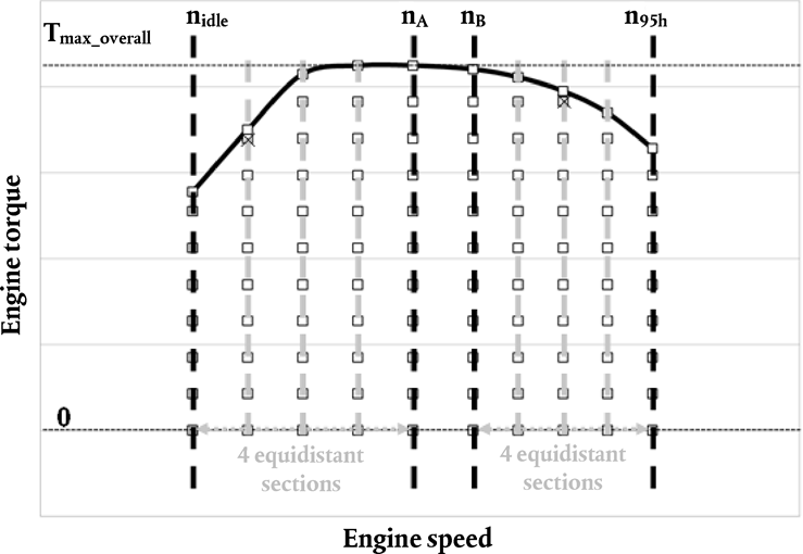
4.3.5.2Grid of target setpoints
The grid of target setpoints is fixed in a normalized way and consists of 10 target engine speed setpoints and 11 target torque setpoints. Conversion of the normalized setpoint definition to the actual target values of engine speed and torque setpoints for the individual engine under test shall be based on the engine full load curve of the CO2-parent engine of the engine CO2-family defined in accordance with Appendix 3 to this Annex and recorded in accordance with paragraph 4.3.1.
4.3.5.2.1Definition of target engine speed setpoints
The 10 target engine speed setpoints are defined by 4 base target engine speed setpoints and 6 additional target engine speed setpoints.
The engine speeds nidle, nlo, npref, n95h and nhi shall be determined from the engine full load curve of the CO2-parent engine of the engine CO2-family defined in accordance with Appendix 3 to this Annex and recorded in accordance with paragraph 4.3.1 by applying the definitions of characteristic engine speeds in accordance with paragraph 7.4.6. of Annex 4 to UN/ECE Regulation 49 Rev.06.
The engine speed n57 shall be determined by the following equation:
n57 = 0,565 × (0,45 × nlo + 0,45 × npref + 0,1 × nhi – nidle) × 2,0327 + nidle
The 4 base target engine speed setpoints are defined as follows:
(1)
Base engine speed 1: nidle
(2)
Base engine speed 2: nA = n57 – 0,05 × (n95h – nidle)
(3)
Base engine speed 3: nB = n57 + 0,08 × (n95h – nidle)
(4)
Base engine speed 4: n95h
The potential distances between the speed setpoints shall be determined by the following equations:
(1)
dnidleA_44 = (nA – nidle) / 4
(2)
dnB95h_44 = (n95h – nB) / 4
(3)
dnidleA_35 = (nA – nidle) / 3
(4)
dnB95h_35 = (n95h – nB) / 5
(5)
dnidleA_53 = (nA – nidle) / 5
(6)
dnB95h_53 = (n95h – nB) / 3
The absolute values of potential deviations between the two sections shall be determined by the following equations:
(1)
dn44 = ABS(dnidleA_44 – dnB95h_44)
(2)
dn35 = ABS(dnidleA_35 – dnB95h_35)
(3)
dn53 = ABS(dnidleA_53 – dnB95h_53)
The 6 additional target engine speed setpoints shall be determined based on the smallest of the three values dn44, dn35 and dn53 in accordance with the following provisions:
(1)
If dn44 is the smallest of the three values, the 6 additional target engine speeds shall be determined by dividing each of the two ranges, one from nidle to nA and the other from nB to n95h, into 4 equidistant sections.
(2)
If dn35 is the smallest of the three values, the 6 additional target engine speeds shall be determined by dividing the range from nidle to nA into 3 equidistant sections and the range from nB to n95h, into 5 equidistant sections.
(3)
If dn53 is the smallest of the three values, the 6 additional target engine speeds shall be determined by dividing the range from nidle to nA into 5 equidistant sections and the range from nB to n95h, into 3 equidistant sections.
Figure 1 exemplarily illustrates the definition of the target engine speed setpoints according to subpoint (1) above.
4.3.5.2.2Definition of target torque setpoints
The 11 target torque setpoints are defined by 2 base target torque setpoints and 9 additional target torque setpoints. The 2 base target torque setpoints are defined by zero engine torque and the maximum engine full load of the CO2-parent engine determined in accordance with paragraph 4.3.1. (overall maximum torque Tmax_overall). The 9 additional target torque setpoints are determined by dividing the range from zero torque to overall maximum torque, Tmax_overall, into 10 equidistant sections.
All target torque setpoints at a particular target engine speed setpoint that exceed the limit value defined by the full load torque value at this particular target engine speed setpoint minus 5 percent of Tmax_overall, shall be replaced with the full load torque value at this particular target engine speed setpoint. Figure 2 exemplarily illustrates the definition of the target torque setpoints.

4.3.5.3Measurement signals and data recording
The following measurement data shall be recorded:
(1)
engine speed
(2)
engine torque corrected in accordance with paragraph 3.1.2
(3)
fuel mass flow consumed by the whole engine system in accordance with paragraph 3.4
(4)
Gaseous pollutants according to the definitions in UN/ECE Regulation 49 Rev.06. Particulate pollutants and ammonia emissions are not required to be monitored during the FCMC testrun.
The measurement of gaseous pollutants shall be carried out in accordance with paragraphs 7.5.1, 7.5.2, 7.5.3, 7.5.5, 7.7.4, 7.8.1, 7.8.2, 7.8.4 and 7.8.5 of Annex 4 to UN/ECE Regulation 49 Rev.06.
For the purpose of paragraph 7.8.4 of Annex 4 to UN/ECE Regulation 49 Rev.06, the term ‘test cycle’ in the paragraph referred to shall be the complete sequence from preconditioning in accordance with paragraph 4.3.5.4 to ending of the test sequence in accordance with paragraph 4.3.5.5.
4.3.5.4Preconditioning of the engine system
The dilution system, if applicable, and the engine shall be started and warmed up in accordance with paragraph 7.4.1. of Annex 4 to UN/ECE Regulation 49 Rev.06.
After warm-up is completed, the engine and sampling system shall be preconditioned by operating the engine for 20 minutes at mode 9, as defined in Table 1 of paragraph 7.2.2. of Annex 4 to UN/ECE Regulation 49 Rev.06, while simultaneously operating the dilution system.
The engine full load curve of the CO2-parent engine of the engine CO2-family and recorded in accordance with paragraph 4.3.1 shall be used for the denormalization of the reference values of mode 9 performed in accordance with paragraphs 7.4.6, 7.4.7 and 7.4.8 of Annex 4 to UN/ECE Regulation 49 Rev.06.
Directly after completion of preconditioning, the target values for engine speed and torque shall be changed linearly within 20 to 46 seconds to match the first target setpoint of the test sequence according to paragraph 4.3.5.5. If the first target setpoint is reached within less than 46 seconds, the remaining time up to 46 seconds shall be used for stabilization.
4.3.5.5Test sequence
The test sequence consists of steady state target setpoints with defined engine speed and torque at each target setpoint in accordance with paragraph 4.3.5.2 and defined ramps to move from one target setpoint to the next.
The highest target torque setpoint at each target engine speed shall be operated with maximum operator demand.
The first target setpoint is defined at the highest target engine speed setpoint and highest target torque setpoint.
The following steps shall be performed to cover all target setpoints:
(1)
The engine shall be operated for 95 ± 3 seconds at each target setpoint. The first 55 ± 1 seconds at each target setpoint are considered as a stabilization period,. During the following period of 30 ± 1 seconds the engine speed mean value shall be controlled as follows:
(a)
The engine speed mean value shall be held at the target engine speed setpoint within ± 1 percent of the highest target engine speed.
(b)
Except for the points at full load, the engine torque mean value shall be held at the target torque setpoint within a tolerance of ± 20 Nm or ± 2 percent of the overall maximum torque, Tmax_overall, whichever is greater.
The recorded values in accordance with paragraph 4.3.5.3 shall be stored as averaged value over the period of 30 ± 1 seconds. The remaining period of 10 ± 1 seconds may be used for data post-processing and storage if necessary. During this period the engine target setpoint shall be kept.
(2)
After the measurement at one target setpoint is completed, the target value for engine speed shall be kept constant within ± 20 min– 1 of the target engine speed setpoint and the target value for torque shall be decreased linearly within 20±1 seconds to match the next lower target torque setpoint. Then the measurement shall be performed according to subpoint (1).
(3)
After the zero torque setpoint has been measured in subpoint (1), the target engine speed shall be decreased linearly to the next lower target engine speed setpoint while at the same time the target torque shall be increased linearly to the highest target torque setpoint at the next lower target engine speed setpoint within 20 to 46 seconds. If the next target setpoint is reached within less than 46 seconds, the remaining time up to 46 seconds shall be used for stabilization. Then the measurement shall be performed by starting the the stabilization procedure according to subpoint (1) and afterwards the target torque setpoints at constant target engine speed shall be adjusted according to subpoint (2).
Figure 3 illustrates the three different steps to be performed at each measurement setpoint for the test according to subpoint (1) above.

Figure 4 exemplarily illustrates the sequence of steady state measurement setpoints to be followed for the test.

4.3.5.6Data evaluation for emission monitoring
Gaseous pollutants in accordance with paragraph 4.3.5.3 shall be monitored during the FCMC. The definitions of characteristic engine speeds in accordance with paragraph 7.4.6. of Annex 4 to UN/ECE R.49.06 shall apply.
4.3.5.6.1Definition of control area
The control area for emission monitoring during the FCMC shall be determined in accordance with paragraphs 4.3.5.6.1.1 and 4.3.5.6.1.2.
4.3.5.6.1.1Engine speed range for the control area
(1)
The engine speed range for the control area shall be defined based on the engine full load curve of the CO2-parent engine of the engine CO2-family defined in accordance with Appendix 3 to this Annex and recorded in accordance with paragraph 4.3.1.
(2)
The control area shall include all engine speeds greater than or equal to the 30th percentile cumulative speed distribution, determined from all engine speeds including idle speed sorted in ascending order, over the hotstart WHTC test cycle performed in accordance with paragraph 4.3.3 (n30) for the engine full load curve referred to the subpoint (1).
(3)
The control area shall include all engine speeds lower than or equal to nhi determined from the engine full load curve referred to in the subpoint (1)
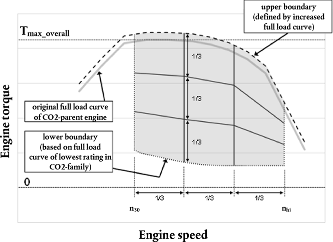
4.3.5.6.1.2Engine torque and power range for the control area
(1)
The lower boundary of the engine torque range for the control area shall be defined based on the engine full load curve of the engine with the lowest rating of all engines within the engine CO2-family and recorded in accordance with paragraph 4.3.1.
(2)
The control area shall include all engine load points with a torque value greater than or equal to 30 percent of the maximum torque value determined from the engine full load curve referred to in subpoint (1).
(3)
Notwithstanding the provisions of subpoint (2), speed and torque points below 30 percent of the maximum power value, determined from the engine full load curve referred to in subpoint (1), shall be excluded from the control area.
(4)
Notwithstanding the provisions of subpoints (2) and (3), the upper boundary of the control area shall be based on the engine full load curve of the CO2-parent engine of the engine CO2-family defined in accordance with Appendix 3 to this Annex and recorded in accordance with paragraph 4.3.1. The torque value for each engine speed determined from the engine full load curve of the CO2-parent engine shall be increased by 5 percent of the overall maximum torque, Tmax_overall, defined in accordance with paragraph 4.3.5.2.2. The modified increased engine full load curve of the CO2-parent engine shall be used as upper boundary of the control area.
Figure 5 exemplarily illustrates the definition of the engine speed, torque and power range for the control area.

4.3.5.6.2Definition of the grid cells
The control area defined in accordance with paragraph 4.3.5.6.1 shall be divided into a number of grid cells for emission monitoring during the FCMC.
The grid shall comprise of 9 cells for engines with a rated speed less than 3 000 min– 1 and 12 cells for engines with a rated speed greater than or equal to 3 000 min– 1. The grids shall be defined in accordance with the following provisions:
(1)
The outer boundaries of the grids are aligned to the control area defined according to paragraph 4.3.5.6.1.
(2)
2 vertical lines spaced at equal distance between engine speeds n30 and 1,1 times n95h for 9 cell grids, or 3 vertical lines spaced at equal distance between engine speeds n30 and 1,1 times n95h for 12 cell grids.
(3)
2 lines spaced at equal distance of engine torque (i.e. 1/3) at each vertical line of engine speed defined by subpoints (1) and (2)
All engine speed values in min-1 and all torque values in Newtonmeters defining the boundaries of the grid cells shall be rounded to 2 places to the right of the decimal point in accordance with ASTM E 29-06.
Figure 6 exemplarily illustrates the definition of the grid cells for the control area in the case of 9 cell grid.
4.3.5.6.3Calculation of specific mass emissions
The specific mass emissions of the gaseous pollutants shall be determined as average value for each grid cell defined in accordance with paragraph 4.3.5.6.2. The average value for each grid cell shall be determined as arithmetical mean value of the specific mass emissions over all engine speed and torque points measured during the FCMC located within the same grid cell.
The specific mass emissions of the single engine speed and torque measured during the FCMC shall be determined as averaged value over the 30 ± 1 seconds measurement period defined in accordance with subpoint (1) of paragraph 4.3.5.5.
If an engine speed and torque point is located directly on a line that separates different grid cells from each other, this engine speed and load point shall be taken into account for the average values of all adjacent grid cells.
The calculation of the total mass emissions of each gaseous pollutant for each engine speed and torque point measured during the FCMC, mFCMC,i in grams, over the 30 ± 1 seconds measurement period in accordance with subpoint (1) of paragraph 4.3.5.5 shall be carried out in accordance with paragraph 8 of Annex 4 to UN/ECE Regulation 49 Rev.06.
The actual engine work for each engine speed and torque point measured during the FCMC, WFCMC,i in kWh, over the 30 ± 1 seconds measurement period in accordance with subpoint (1) of paragraph 4.3.5.5 shall be determined from the engine speed and torque values recorded in accordance with paragraph 4.3.5.3.
The specific mass emissions of gaseous pollutants eFCMC,i in g/kWh for each engine speed and torque point measured during the FCMC shall be determined by the following equation:
eFCMC,i = mFCMC,i / WFCMC,i
4.3.5.7Validity of data
4.3.5.7.1Requirements for validation statistics of the FCMC
A linear regression analysis of the actual values of engine speed (nact), engine torque (Mact) and engine power (Pact) on the respective reference values (nref, Mref, Pref) shall be performed for the FCMC. The actual values for nact, Mact and Pact shall be the determined from the values recorded in accordance with paragraph 4.3.5.3.
The ramps to move from one target setpoint to the next shall be excluded from this regression analysis.
To minimize the biasing effect of the time lag between the actual and reference cycle values, the entire engine speed and torque actual signal sequence may be advanced or delayed in time with respect to the reference speed and torque sequence. If the actual signals are shifted, both speed and torque shall be shifted by the same amount in the same direction.
The method of least squares shall be used for the regression analysis in accordance with paragraphs A.3.1 and A.3.2 of Appendix 3 to Annex 4 to UN/ECE Regulation 49 Rev.06, with the best-fit equation having the form as defined in paragraph 7.8.7 of Annex 4 to UN/ECE Regulation 49 Rev.06. It is recommended that this analysis be performed at 1 Hz.
For the purposes of this regression analysis only, omissions of points are permitted where noted in Table 4 (Permitted point omissions from regression analysis) of Annex 4 to UN/ECE Regulation 49 Rev.06 before doing the regression calculation. Additionally, all engine torque and power values at points with maximum operator demand shall be omitted for the purposes of this regression analysis only. However, points omitted for the purposes of regression analysis shall not be omitted for any other calculations in accordance with this Annex. Point omission may be applied to the whole or to any part of the cycle.
For the data to be considered valid, the criteria of Table 3 (Regression line tolerances for the WHSC) of Annex 4 to UN/ECE Regulation 49 Rev.06 shall be met.
4.3.5.7.2Requirements for emission monitoring
The data obtained from the FCMC tests is valid if the specific mass emissions of the regulated gaseous pollutants determined for each grid cell in accordance with paragraph 4.3.5.6.3 meet the applicable limits for gaseous pollutants defined in paragraph 5.2.2 of Annex 10 to UN/ECE Regulation 49 Rev.06. In the case that the number of engine speed and torque points within the same grid cell is less than 3, this paragraph shall not apply for that specific grid cell.
5.Post-processing of measurement data
All calculations defined in this paragraph shall be performed specifically for each engine within one engine CO2-family.
5.1Calculation of engine work
Total engine work over a cycle or a defined period shall be determined from the recorded values of engine power determind in accordance with paragraph 3.1.2 and paragraphs 6.3.5. and 7.4.8. of Annex 4 to UN/ECE Regulation 49 Rev.06.
The engine work over a complete testcycle or over each WHTC-sub-cycle shall be determined by integrating of recorded values of engine power in accordance with the following formula:

where:
Wact, i
=
total engine work over the time period from t0 to t1
t0
=
time at the start of the time period
t1
=
time at the end of the time period
n
=
number of recorded values over the time period from t0 to t1
Pk [0 … n]
=
recorded engine power values over the time period from t0 to t1 in chronological order, where k runs from 0 at t0 to n at t1

5.2Calculation of integrated fuel consumption
Any recorded negative values for the fuel consumption shall be used directly and shall not be set equal to zero for the calculations of the integrated value.
The total fuel mass consumed by the engine over a complete testcycle or over each WHTC-sub-cycle shall be determined by integrating recorded values of fuel massflow in accordance with the following formula:

where:
Σ FCmeas, i
=
total fuel mass consumed by the engine over the time period from t0 to t1
t0
=
time at the start of the time period
t1
=
time at the end of the time period
n
=
number of recorded values over the time period from t0 to t1
mffuel,k [0 … n]
=
recorded fuel massflow values over the time period from t0 to t1 in chronological order, where k runs from 0 at t0 to n at t1

5.3Calculation of specific fuel consumption figures
The correction and balancing factors, which have to be provided as input for the simulation tool, are calculated by the engine pre-processing tool based on the measured specific fuel consumption figures of the engine determined in accordance with paragraphs 5.3.1 and 5.3.2.
5.3.1Specific fuel consumption figures for WHTC correction factor
The specific fuel consumption figures needed for the WHTC correction factor shall be calculated from the actual measured values for the hotstart WHTC recorded in accordance with paragraph 4.3.3 as follows:
SFCmeas, Urban = Σ FCmeas, WHTC-Urban / Wact, WHTC-Urban
SFCmeas, Rural = Σ FCmeas, WHTC- Rural / Wact, WHTC- Rural
SFCmeas, MW = Σ FCmeas, WHTC-MW / Wact, WHTC-M)
where:
SFCmeas, i
=
Specific fuel consumption over the WHTC-sub-cycle i [g/kWh]
Σ FCmeas, i
=
Total fuel mass consumed by the engine over the WHTC-sub-cycle i [g] determined in accordance with paragraph 5.2
Wact, i
=
Total engine work over the WHTC sub-cycle i [kWh] determined in accordance with paragraph 5.1
The 3 different sub-cycles of the WHTC – urban, rural and motorway – shall be defined as follows:
(1)
urban: from cycle start to ≤ 900 seconds from cycle start
(2)
rural: from > 900 seconds to ≤ 1 380 seconds from cycle start
(3)
motorway (MW): from > 1 380 seconds from cycle start to cycle end
5.3.2Specific fuel consumption figures for cold-hot emission balancing factor
The specific fuel consumption figures needed for the cold-hot emission balancing factor shall be calculated from the actual measured values for both, the hotstart and coldstart WHTC test recorded in accordance with paragraph 4.3.3. The calculations shall be performed for both, the hotstart and coldstart WHTC separately as follows:
SFCmeas, hot = Σ FCmeas, hot / Wact, hot
SFCmeas, cold = Σ FCmeas, cold / Wact, cold
where:
SFCmeas, j
=
Specific fuel consumption [g/kWh]
Σ FCmeas, j
=
Total fuel consumption over the WHTC [g] determined in accordance with paragraph 5.2 of this Annex
Wact, j
=
Total engine work over the WHTC [kWh] determined in accordance with paragraph 5.1 of this Annex
5.3.3Specific fuel consumption figures over WHSC
The specific fuel consumption over the WHSC shall be calculated from the actual measured values for the WHSC recorded in accordance with paragraph 4.3.4 as follows:
SFCWHSC = (Σ FCWHSC) / (WWHSC)
where:
SFCWHSC
=
Specific fuel consumption over WHSC [g/kWh]
Σ FCWHSC
=
Total fuel consumption over the WHSC [g] determined in accordance with paragraph 5.2 of this Annex
WWHSC
=
Total engine work over the WHSC [kWh] determined in accordance with paragraph 5.1 of this Annex
5.3.3.1Corrected specific fuel consumption figures over WHSC
The calculated specific fuel consumption over the WHSC, SFCWHSC, determined in accordance with paragraph 5.3.3 shall be adjusted to a corrected value, SFCWHSC,corr, in order to account for the difference between the NCV of the fuel used during testing and the standard NCV for the respective engine fuel technology in accordance with the following equation:

where:
SFCWHSC,corr
=
Corrected specific fuel consumption over WHSC [g/kWh]
SFCWHSC
=
Specific fuel consumption over WHSC [g/kWh]
NCVmeas
=
NCV of the fuel used during testing determined in accordance with paragraph 3.2 [MJ/kg]
NCVstd
=
Standard NCV in accordance with Table 4 [MJ/kg]
Table 4
Standard net calorific values of fuel types
| Fuel type / engine type | Reference fuel type | Standard NCV [MJ/kg] |
|---|---|---|
| Diesel / CI | B7 | 42,7 |
| Ethanol / CI | ED95 | 25,7 |
| Petrol / PI | E10 | 41,5 |
| Ethanol / PI | E85 | 29,1 |
| LPG / PI | LPG Fuel B | 46,0 |
| Natural Gas / PI | G25 | 45,1 |
5.3.3.2Special provisions for B7 reference fuel
In the case that reference fuel of the type B7 (Diesel /CI) in accordance with paragraph 3.2 was used during testing, the standardization correction in accordance with paragraph 5.3.3.1 shall not be performed and the corrected value, SFCWHSC,corr, shall be set to the uncorrected value SFCWHSC.
5.4Correction factor for engines equipped with exhaust after-treatment systems that are regenerated on a periodic basis
For engines equipped with exhaust after-treatment systems that are regenerated on a periodic basis defined in accordance with paragraph 6.6.1 of Annex 4 to UN/ECE Regulation 49 Rev.06, fuel consumption shall be adjusted to account for regeneration events by a correction factor.
This correction factor, CFRegPer, shall be determined in accordance with paragraph 6.6.2 of Annex 4 to UN/ECE Regulation 49 Rev.06.
For engines equipped with exhaust after-treatment systems with continuous regeneration, defined in accordance with paragraph 6.6 of Annex 4 to UN/ECE Regulation 49 Rev.06, no correction factor shall be determined and the value of the factor CFRegPer shall be set to 1.
The engine full load curve recorded in accordance with paragraph 4.3.1 shall be used for the denormalization of the WHTC reference cycle and all calculations of reference values performed in accordance with paragraphs 7.4.6, 7.4.7 and 7.4.8 of Annex 4 to UN/ECE Regulation 49 Rev.06.
In addition to the provisions defined in Annex 4 to UN/ECE Regulation 49 Rev.06 the actual fuel mass flow consumed by the engine in accordance with paragraph 3.4 shall be recorded for each WHTC hot start test performed in accordance with paragraph 6.6.2 of Annex 4 to UN/ECE Regulation 49 Rev.06.
The specific fuel consumption for each WHTC hot start test performed shall be calculated by the following equation:
SFCmeas, m = (Σ FCmeas, m) / (Wact, m)
where:
SFCmeas, m
=
Specific fuel consumption [g/kWh]
Σ FCmeas,m
=
Total fuel consumption over the WHTC [g] determined in accordance with paragraph 5.2 of this Annex
Wact, m
=
Total engine work over the WHTC [kWh] determined in accordance with paragraph 5.1 of this Annex
m
=
Index defining each individual WHTC hot start test
The specific fuel consumption values for the individual WHTC tests shall be weighted by the following equation:

where:
n
=
the number of WHTC hot start tests without regeneration
nr
=
the number of WHTC hot start tests with regeneration (minimum number is one test)
SFCavg
=
the average specific fuel consumption from all WHTC hot start tests without regeneration [g/kWh]
SFCavg,r
=
the average specific fuel consumption from all WHTC hot start tests with regeneration [g/kWh]
The correction factor, CFRegPer, shall be calculated by the following equation:

6.Application of engine pre-processing tool
The engine pre-processing tool shall be executed for each engine within one engine CO2-family using the input defined in paragraph 6.1.
The output data of the engine pre-processing tool shall be the final result of the engine test procedure and shall be documented.
6.1Input data for the engine pre-processing tool
The following input data shall be generated by the test procedures specified in this Annex and shall be the input to the engine pre-processing tool.
6.1.1Full load curve of the CO2-parent engine
The input data shall be the engine full load curve of the CO2-parent engine of the engine CO2-family defined in accordance with Appendix 3 to this Annex and recorded in accordance with paragraph 4.3.1.
In the case that upon request of the manufacturer the provisions defined in Article 15(5) of this Regulation are applied, the engine full load curve of that specific engine recorded in accordance with paragraph 4.3.1 shall be used as input data.
The input data shall be provided in the file format of ‘comma separated values’ with the separator character being the Unicode Character ‘COMMA’ (U+002C) (‘,’). The first line of the file shall be used as a header and not contain any recorded data. The recorded data shall start from the second line of the file.
The first column of the file shall be the engine speed in min– 1 rounded to 2 places to the right of the decimal point in accordance with ASTM E 29-06. The second column shall be the torque in Nm rounded to 2 places to the right of the decimal point in accordance with ASTM E 29-06.
6.1.2Full load curve
The input data shall be the engine full load curve of the engine recorded in accordance with paragraph 4.3.1.
The input data shall be provided in the file format of ‘comma separated values’ with the separator character being the Unicode Character ‘COMMA’ (U+002C) (‘,’). The first line of the file shall be used as a header and not contain any recorded data. The recorded data shall start from the second line of the file.
The first column of the file shall be the engine speed in min– 1 rounded to 2 places to the right of the decimal point in accordance with ASTM E 29-06. The second column shall be the torque in Nm rounded to 2 places to the right of the decimal point in accordance with ASTM E 29-06.
6.1.3Motoring curve of the CO2-parent engine
The input data shall be the engine motoring curve of the CO2-parent engine of the engine CO2-family defined in accordance with Appendix 3 to this Annex and recorded in accordance with paragraph 4.3.2.
In the case that upon request of the manufacturer the provisions defined in Article 15(5) of this Regulation are applied, the engine motoring curve of that specific engine recorded in accordance with paragraph 4.3.2 shall be used as input data.
The input data shall be provided in the file format of ‘comma separated values’ with the separator character being the Unicode Character ‘COMMA’ (U+002C) (‘,’). The first line of the file shall be used as a header and not contain any recorded data. The recorded data shall start from the second line of the file.
The first column of the file shall be the engine speed in min– 1 rounded to 2 places to the right of the decimal point in accordance with ASTM E 29-06. The second column shall be the torque in Nm rounded to 2 places to the right of the decimal point in accordance with ASTM E 29-06.
6.1.4Fuel consumption map of the CO2-parent engine
The input data shall be the values of engine speed, engine torque and fuel massflow determined for the CO2-parent engine of the engine CO2-family defined in accordance with Appendix 3 to this Annex and recorded in accordance with paragraph 4.3.5.
In the case that upon request of the manufacturer the provisions defined in Article 15(5) of this Regulation are applied, the values of engine speed, engine torque and fuel massflow determined for that specific engine recorded in accordance with paragraph 4.3.5 shall be used as input data.
The input data shall only consist of the average measurement values of engine speed, engine torque and fuel massflow over the 30 ± 1 seconds measurement period determined in accordance with subpoint (1) of paragraph 4.3.5.5.
The input data shall be provided in the file format of ‘comma separated values’ with the separator character being the Unicode Character ‘COMMA’ (U+002C) (‘,’). The first line of the file shall be used as a header and not contain any recorded data. The recorded data shall start from the second line of the file.
The first column of the file shall be the engine speed in min– 1 rounded to 2 places to the right of the decimal point in accordance with ASTM E 29-06. The second column shall be the torque in Nm rounded to 2 places to the right of the decimal point in accordance with ASTM E 29-06. The third column shall be the fuel massflow in g/h rounded to 2 places to the right of the decimal point in accordance with ASTM E 29-06.
6.1.5Specific fuel consumption figures for WHTC correction factor
The input data shall be the three values for specific fuel consumption over the different sub-cycles of the WHTC – urban, rural and motorway – in g/kWh determined in accordance with paragraph 5.3.1.
The values shall be rounded to 2 places to the right of the decimal point in accordance with ASTM E 29-06.
6.1.6Specific fuel consumption figures for cold-hot emission balancing factor
The input data shall be the two values for specific fuel consumption over the hotstart and coldstart WHTC in g/kWh determined in accordance with paragraph 5.3.2.
The values shall be rounded to 2 places to the right of the decimal point in accordance with ASTM E 29-06.
6.1.7Correction factor for engines equipped with exhaust after-treatment systems that are regenerated on a periodic basis
The input data shall be the correction factor CFRegPer determined in accordance with paragraph 5.4.
For engines equipped with exhaust after-treatment systems with continuous regeneration, defined in accordance with paragraph 6.6.1 of Annex 4 to UN/ECERegulation 49 Rev.06, this factor shall be set to 1 in accordance with paragraph5.4.
The value shall be rounded to 2 places to the right of the decimal point in accordance with ASTM E 29-06.
6.1.8NCV of test fuel
The input data shall be the NCV of the test fuel in MJ/kg determined in accordance with paragraph 3.2.
The value shall be rounded to 3 places to the right of the decimal point in accordance with ASTM E 29-06.
6.1.9Type of test fuel
The input data shall be the type of the test fuel selected in accordance with paragraph 3.2.
6.1.10Engine idle speed of the CO2-parent engine
The input data shall be the engine idle speed, nidle, in min– 1 of the CO2-parent engine of the engine CO2-family defined in accordance with Appendix 3 to this Annex as declared by the manufacturer in the application for certification in the information document drawn up in accordance with the model set out in Appendix 2.
In the case that upon request of the manufacturer the provisions defined in Article 15(5) of this Regulation are applied, the engine idle speed of that specific engine shall be used as input data.
The value shall be rounded to the nearest whole number in accordance with ASTM E 29-06.
6.1.11Engine idle speed
The input data shall be the engine idle speed, nidle, in min– 1 of the engine as declared by the manufacturer in the application for certification in the information document drawn up in accordance with the model set out in Appendix 2 to this Annex.
The value shall be rounded to the nearest whole number in accordance with ASTM E 29-06.
6.1.12Engine displacement
The input data shall be the displacement in ccm of the engine as declared by the manufacturer at the application for certification in the information document drawn up in accordance with the model set out in Appendix 2 to this Annex.
The value shall be rounded to the nearest whole number in accordance with ASTM E 29-06.
6.1.13Engine rated speed
The input data shall be the rated speed in min– 1 of the engine as declared by the manufacturer at the application for certification in point 3.2.1.8. of the information document in accordance with Appendix 2 to this Annex.
The value shall be rounded to the nearest whole number in accordance with ASTM E 29-06.
6.1.14Engine rated power
The input data shall be the rated power in kW of the engine as declared by the manufacturer at the application for certification in point 3.2.1.8. of the information document in accordance with Appendix 2 to this Annex.
The value shall be rounded to the nearest whole number in accordance with ASTM E 29-06.
6.1.15Manufacturer
The input data shall be the name of the engine manufacturer as a sequence of characters in ISO8859-1 encoding.
6.1.16Model
The input data shall be the name of the engine model as a sequence of characters in ISO8859-1 encoding.
6.1.17Technical Report ID
The input data shall be an unique identifier of the technical report compiled for the type approval of the specific engine. This identifier shall be provided as a sequence of characters in ISO8859-1 encoding.
Appendix 1 MODEL OF A CERTIFICATE OF A COMPONENT, SEPARATE TECHNICAL UNIT OR SYSTEM
Maximum format: A4 (210 × 297 mm)
CERTIFICATE ON CO2 EMISSIONS AND FUEL CONSUMPTION RELATED PROPERTIES OF AN ENGINE FAMILY
| Communication concerning:
| Administration stamp |
of a certificate on CO2 emission and fuel consumption related properties of an engine family in accordance with Commission Regulation (EU) 2017/2400.
Commission Regulation (EU) 2017/2400 as last amended by ….
Certification number:
Hash:
Reason for extension:
SECTION I
0.1.Make (trade name of manufacturer):
0.2.Type:
0.3.Means of identification of type
0.3.1.Location of the certification marking:
0.3.2Method of affixing certification marking:
0.5.Name and address of manufacturer:
0.6.Name(s) and address(es) of assembly plant(s):
0.7.Name and address of the manufacturer's representative (if any)
SECTION II
1.Additional information (where applicable): see Addendum
2.Approval authority responsible for carrying out the tests:
3.Date of test report:
4.Number of test report:
5.Remarks (if any): see Addendum
6.Place:
7.Date:
8.Signature:
Attachments:
Information package. Test report.
Appendix 2 Engine Information Document
Notes regarding filling in the tables:
Letters A, B, C, D, E corresponding to engine CO2-family members shall be replaced by the actual engine CO2-family members' names.
In case when for a certain engine characteristic same value/description applies for all engine CO2-family members the cells corresponding to A-E shall be merged.
In case the engine CO2-family consists of more than 5 members, new columns may be added.
The ‘Appendix to information document’ shall be copied and filled in for each engine within an CO2-family separately.
Explanatory footnotes can be found at the very end of this Appendix.
| CO2-parent engine | Engine CO2-family members | ||||||
|---|---|---|---|---|---|---|---|
| A | B | C | D | E | |||
| 0. | General | ||||||
| 0.l. | Make (trade name of manufacturer) | ||||||
| 0.2. | Type | ||||||
| 0.2.1. | Commercial name(s) (if available) | ||||||
| 0.5. | Name and address of manufacturer | ||||||
| 0.8. | Name(s) and address (es) of assembly plant(s) | ||||||
| 0.9. | Name and address of the manufacturer's representative (if any) | ||||||
PART 1 Essential characteristics of the (parent) engine and the engine types within an engine family
| Parent engine or engine type | Engine CO2-family members | |||||||||
|---|---|---|---|---|---|---|---|---|---|---|
| A | B | C | D | E | ||||||
| 3.2. | Internal combustion engine | |||||||||
| 3.2.1. | Specific engine information | |||||||||
| 3.2.1.1. | Working principle: positive ignition/compression ignition (1)Cycle four stroke/two stroke/ rotary (1) | |||||||||
| 3.2.1.2. | Number and arrangement of cylinders | |||||||||
| 3.2.1.2.1. | Bore (3) mm | |||||||||
| 3.2.1.2.2. | Stroke (3) mm | |||||||||
| 3.2.1.2.3. | Firing order | |||||||||
| 3.2.1.3. | Engine capacity (4) cm3 | |||||||||
| 3.2.1.4. | Volumetric compression ratio (5) | |||||||||
| 3.2.1.5. | Drawings of combustion chamber, piston crown and, in the case of positive ignition engines, piston rings | |||||||||
| 3.2.1.6. | Normal engine idling speed (5) min– 1 | |||||||||
| 3.2.1.6.1. | High engine idling speed (5) min– 1 | |||||||||
| 3.2.1.7. | Carbon monoxide content by volume in the exhaust gas with the engine idling (5): % as stated by the manufacturer (positive ignition engines only) | |||||||||
| 3.2.1.8. | Maximum net power (6) … kW at … min– 1 (manufacturer's declared value) | |||||||||
| 3.2.1.9. | Maximum permitted engine speed as prescribed by the manufacturer (min– 1) | |||||||||
| 3.2.1.10. | Maximum net torque (6) (Nm) at (min– 1) (manufacturer's declared value) | |||||||||
| 3.2.1.11. | Manufacturer references of the documentation package required by paragraphs 3.1., 3.2. and 3.3. of UN/ECE Regulation 49 Rev. 06 enabling the Type Approval Authority to evaluate the emission control strategies and the systems on-board the engine to ensure the correct operation of NOx control measures | |||||||||
| 3.2.2. | Fuel | |||||||||
| 3.2.2.2. | Heavy duty vehicles Diesel/Petrol/LPG/NG-H/NG-L/NG-HL/Ethanol (ED95)/ Ethanol (E85) (1) | |||||||||
| 3.2.2.2.1. | Fuels compatible with use by the engine declared by the manufacturer in accordance with paragraph 4.6.2. of UN/ECE Regulation 49 Rev. 06 (as applicable) | |||||||||
| 3.2.4. | Fuel feed | |||||||||
| 3.2.4.2. | By fuel injection (compression ignition only): Yes/No (1) | |||||||||
| 3.2.4.2.1. | System description | |||||||||
| 3.2.4.2.2. | Working principle: direct injection/pre-chamber/swirl chamber (1) | |||||||||
| 3.2.4.2.3. | Injection pump | |||||||||
| 3.2.4.2.3.1. | Make(s) | |||||||||
| 3.2.4.2.3.2. | Type(s) | |||||||||
| 3.2.4.2.3.3. | Maximum fuel delivery (1) (5) … mm3 /stroke or cycle at an engine speed of … min– 1 or, alternatively, a characteristic diagram(When boost control is supplied, state the characteristic fuel delivery and boost pressure versus engine speed) | |||||||||
| 3.2.4.2.3.4. | Static injection timing (5) | |||||||||
| 3.2.4.2.3.5. | Injection advance curve (5) | |||||||||
| 3.2.4.2.3.6. | Calibration procedure: test bench/engine (1) | |||||||||
| 3.2.4.2.4. | Governor | |||||||||
| 3.2.4.2.4.1. | Type | |||||||||
| 3.2.4.2.4.2. | Cut-off point | |||||||||
| 3.2.4.2.4.2.1. | Speed at which cut-off starts under load (min– 1) | |||||||||
| 3.2.4.2.4.2.2. | Maximum no-load speed (min– 1) | |||||||||
| 3.2.4.2.4.2.3. | Idling speed (min– 1) | |||||||||
| 3.2.4.2.5. | Injection piping | |||||||||
| 3.2.4.2.5.1. | Length (mm) | |||||||||
| 3.2.4.2.5.2. | Internal diameter (mm) | |||||||||
| 3.2.4.2.5.3. | Common rail, make and type | |||||||||
| 3.2.4.2.6. | Injector(s) | |||||||||
| 3.2.4.2.6.1. | Make(s) | |||||||||
| 3.2.4.2.6.2. | Type(s) | |||||||||
| 3.2.4.2.6.3. | Opening pressure (5): | kPa or characteristic diagram (5) | ||||||||
| 3.2.4.2.7. | Cold start system | |||||||||
| 3.2.4.2.7.1. | Make(s) | |||||||||
| 3.2.4.2.7.2. | Type(s) | |||||||||
| 3.2.4.2.7.3. | Description | |||||||||
| 3.2.4.2.8. | Auxiliary starting aid | |||||||||
| 3.2.4.2.8.1. | Make(s) | |||||||||
| 3.2.4.2.8.2. | Type(s) | |||||||||
| 3.2.4.2.8.3. | System description | |||||||||
| 3.2.4.2.9. | Electronic controlled injection: Yes/No (1) | |||||||||
| 3.2.4.2.9.1. | Make(s) | |||||||||
| 3.2.4.2.9.2. | Type(s) | |||||||||
| 3.2.4.2.9.3. | Description of the system (in the case of systems other than continuous injection give equivalent details) | |||||||||
| 3.2.4.2.9.3.1. | Make and type of the control unit (ECU) | |||||||||
| 3.2.4.2.9.3.2. | Make and type of the fuel regulator | |||||||||
| 3.2.4.2.9.3.3. | Make and type of the air-flow sensor | |||||||||
| 3.2.4.2.9.3.4. | Make and type of fuel distributor | |||||||||
| 3.2.4.2.9.3.5. | Make and type of the throttle housing | |||||||||
| 3.2.4.2.9.3.6. | Make and type of water temperature sensor | |||||||||
| 3.2.4.2.9.3.7. | Make and type of air temperature sensor | |||||||||
| 3.2.4.2.9.3.8. | Make and type of air pressure sensor | |||||||||
| 3.2.4.2.9.3.9. | Software calibration number(s) | |||||||||
| 3.2.4.3. | By fuel injection (positive ignition only): Yes/No (1) | |||||||||
| 3.2.4.3.1. | Working principle: intake manifold (single-/multi-point/direct injection (1)/other specify) | |||||||||
| 3.2.4.3.2. | Make(s) | |||||||||
| 3.2.4.3.3. | Type(s) | |||||||||
| 3.2.4.3.4. | System description (In the case of systems other than continuous injection give equivalent details) | |||||||||
| 3.2.4.3.4.1. | Make and type of the control unit (ECU) | |||||||||
| 3.2.4.3.4.2. | Make and type of fuel regulator | |||||||||
| 3.2.4.3.4.3. | Make and type of air-flow sensor | |||||||||
| 3.2.4.3.4.4. | Make and type of fuel distributor | |||||||||
| 3.2.4.3.4.5. | Make and type of pressure regulator | |||||||||
| 3.2.4.3.4.6. | Make and type of micro switch | |||||||||
| 3.2.4.3.4.7. | Make and type of idling adjustment screw | |||||||||
| 3.2.4.3.4.8. | Make and type of throttle housing | |||||||||
| 3.2.4.3.4.9. | Make and type of water temperature sensor | |||||||||
| 3.2.4.3.4.10. | Make and type of air temperature sensor | |||||||||
| 3.2.4.3.4.11. | Make and type of air pressure sensor | |||||||||
| 3.2.4.3.4.12. | Software calibration number(s) | |||||||||
| 3.2.4.3.5. | Injectors: opening pressure (5) (kPa) or characteristic diagram (5) | |||||||||
| 3.2.4.3.5.1. | Make | |||||||||
| 3.2.4.3.5.2. | Type | |||||||||
| 3.2.4.3.6. | Injection timing | |||||||||
| 3.2.4.3.7. | Cold start system | |||||||||
| 3.2.4.3.7.1. | Operating principle(s) | |||||||||
| 3.2.4.3.7.2. | Operating limits/settings (1) (5) | |||||||||
| 3.2.4.4. | Feed pump | |||||||||
| 3.2.4.4.1. | Pressure (5) (kPa) or characteristic diagram (5) | |||||||||
| 3.2.5. | Electrical system | |||||||||
| 3.2.5.1. | Rated voltage (V), positive/negative ground (1) | |||||||||
| 3.2.5.2. | Generator | |||||||||
| 3.2.5.2.1. | Type | |||||||||
| 3.2.5.2.2. | Nominal output (VA) | |||||||||
| 3.2.6. | Ignition system (spark ignition engines only) | |||||||||
| 3.2.6.1. | Make(s) | |||||||||
| 3.2.6.2. | Type(s) | |||||||||
| 3.2.6.3. | Working principle | |||||||||
| 3.2.6.4. | Ignition advance curve or map (5) | |||||||||
| 3.2.6.5. | Static ignition timing (5) (degrees before TDC) | |||||||||
| 3.2.6.6. | Spark plugs | |||||||||
| 3.2.6.6.1. | Make | |||||||||
| 3.2.6.6.2. | Type | |||||||||
| 3.2.6.6.3. | Gap setting (mm) | |||||||||
| 3.2.6.7. | Ignition coil(s) | |||||||||
| 3.2.6.7.1. | Make | |||||||||
| 3.2.6.7.2. | Type | |||||||||
| 3.2.7. | Cooling system: liquid/air (1) | |||||||||
| 3.2.7.2. | Liquid | |||||||||
| 3.2.7.2.1. | Nature of liquid | |||||||||
| 3.2.7.2.2. | Circulating pump(s): Yes/No (1) | |||||||||
| 3.2.7.2.3. | Characteristics | |||||||||
| 3.2.7.2.3.1. | Make(s) | |||||||||
| 3.2.7.2.3.2. | Type(s) | |||||||||
| 3.2.7.2.4. | Drive ratio(s) | |||||||||
| 3.2.7.3. | Air | |||||||||
| 3.2.7.3.1. | Fan: Yes/No (1) | |||||||||
| 3.2.7.3.2. | Characteristics | |||||||||
| 3.2.7.3.2.1. | Make(s) | |||||||||
| 3.2.7.3.2.2. | Type(s) | |||||||||
| 3.2.7.3.3. | Drive ratio(s) | |||||||||
| 3.2.8. | Intake system | |||||||||
| 3.2.8.1. | Pressure charger: Yes/No (1) | |||||||||
| 3.2.8.1.1. | Make(s) | |||||||||
| 3.2.8.1.2. | Type(s) | |||||||||
| 3.2.8.1.3. | Description of the system (e.g. maximum charge pressure … kPa, wastegate, if applicable) | |||||||||
| 3.2.8.2. | Intercooler: Yes/No (1) | |||||||||
| 3.2.8.2.1. | Type: air-air/air-water (1) | |||||||||
| 3.2.8.3. | Intake depression at rated engine speed and at 100 % load (compression ignition engines only) | |||||||||
| 3.2.8.3.1. | Minimum allowable (kPa) | |||||||||
| 3.2.8.3.2. | Maximum allowable (kPa) | |||||||||
| 3.2.8.4. | Description and drawings of inlet pipes and their accessories (plenum chamber, heating device, additional air intakes, etc.) | |||||||||
| 3.2.8.4.1. | Intake manifold description (include drawings and/or photos) | |||||||||
| 3.2.9. | Exhaust system | |||||||||
| 3.2.9.1. | Description and/or drawings of the exhaust manifold | |||||||||
| 3.2.9.2. | Description and/or drawing of the exhaust system | |||||||||
| 3.2.9.2.1. | Description and/or drawing of the elements of the exhaust system that are part of the engine system | |||||||||
| 3.2.9.3. | Maximum allowable exhaust back pressure at rated engine speed and at 100 % load (compression ignition engines only)(kPa) (7) | |||||||||
| 3.2.9.7. | Exhaust system volume (dm3) | |||||||||
| 3.2.9.7.1. | Acceptable Exhaust system volume: (dm3) | |||||||||
| 3.2.10. | Minimum cross-sectional areas of inlet and outlet ports and port geometry | |||||||||
| 3.2.11. | Valve timing or equivalent data | |||||||||
| 3.2.11.1. | Maximum lift of valves, angles of opening and closing, or timing details of alternative distribution systems, in relation to dead centers. For variable timing system, minimum and maximum timing | |||||||||
| 3.2.11.2. | Reference and/or setting range (7) | |||||||||
| 3.2.12. | Measures taken against air pollution | |||||||||
| 3.2.12.1.1. | Device for recycling crankcase gases: Yes/No (1)If yes, description and drawingsIf no, compliance with paragraph 6.10. of Annex 4 of UN/ECE Regulation 49 Rev. 06 required | |||||||||
| 3.2.12.2. | Additional pollution control devices (if any, and if not covered by another heading) | |||||||||
| 3.2.12.2.1. | Catalytic converter: Yes/No (1) | |||||||||
| 3.2.12.2.1.1. | Number of catalytic converters and elements (provide this information below for each separate unit) | |||||||||
| 3.2.12.2.1.2. | Dimensions, shape and volume of the catalytic converter(s) | |||||||||
| 3.2.12.2.1.3. | Type of catalytic action | |||||||||
| 3.2.12.2.1.4. | Total charge of precious metals | |||||||||
| 3.2.12.2.1.5. | Relative concentration | |||||||||
| 3.2.12.2.1.6. | Substrate (structure and material) | |||||||||
| 3.2.12.2.1.7. | Cell density | |||||||||
| 3.2.12.2.1.8. | Type of casing for the catalytic converter(s) | |||||||||
| 3.2.12.2.1.9. | Location of the catalytic converter(s) (place and reference distance in the exhaust line) | |||||||||
| 3.2.12.2.1.10. | Heat shield: Yes/No (1) | |||||||||
| 3.2.12.2.1.11. | Regeneration systems/method of exhaust after treatment systems, description | |||||||||
| 3.2.12.2.1.11.5. | Normal operating temperature range (K) | |||||||||
| 3.2.12.2.1.11.6. | Consumable reagents: Yes/No (1) | |||||||||
| 3.2.12.2.1.11.7. | Type and concentration of reagent needed for catalytic action | |||||||||
| 3.2.12.2.1.11.8. | Normal operational temperature range of reagent K | |||||||||
| 3.2.12.2.1.11.9. | International standard | |||||||||
| 3.2.12.2.1.11.10. | Frequency of reagent refill: continuous/maintenance (1) | |||||||||
| 3.2.12.2.1.12. | Make of catalytic converter | |||||||||
| 3.2.12.2.1.13. | Identifying part number | |||||||||
| 3.2.12.2.2. | Oxygen sensor: Yes/No (1) | |||||||||
| 3.2.12.2.2.1. | Make | |||||||||
| 3.2.12.2.2.2. | Location | |||||||||
| 3.2.12.2.2.3. | Control range | |||||||||
| 3.2.12.2.2.4. | Type | |||||||||
| 3.2.12.2.2.5. | Indentifying part number | |||||||||
| 3.2.12.2.3. | Air injection: Yes/No (1) | |||||||||
| 3.2.12.2.3.1. | Type (pulse air, air pump, etc.) | |||||||||
| 3.2.12.2.4. | Exhaust gas recirculation (EGR): Yes/No (1) | |||||||||
| 3.2.12.2.4.1. | Characteristics (make, type, flow, etc) | |||||||||
| 3.2.12.2.6. | Particulate trap (PT): Yes/No (1) | |||||||||
| 3.2.12.2.6.1. | Dimensions, shape and capacity of the particulate trap | |||||||||
| 3.2.12.2.6.2. | Design of the particulate trap | |||||||||
| 3.2.12.2.6.3. | Location (reference distance in the exhaust line) | |||||||||
| 3.2.12.2.6.4. | Method or system of regeneration, description and/or drawing | |||||||||
| 3.2.12.2.6.5. | Make of particulate trap | |||||||||
| 3.2.12.2.6.6. | Indentifying part number | |||||||||
| 3.2.12.2.6.7. | Normal operating temperature (K) and pressure (kPa) ranges | |||||||||
| 3.2.12.2.6.8. | In the case of periodic regeneration | |||||||||
| 3.2.12.2.6.8.1.1. | Number of WHTC test cycles without regeneration (n) | |||||||||
| 3.2.12.2.6.8.2.1. | Number of WHTC test cycles with regeneration (nR) | |||||||||
| 3.2.12.2.6.9. | Other systems: Yes/No (1) | |||||||||
| 3.2.12.2.6.9.1. | Description and operation | |||||||||
| 3.2.12.2.7. | On-board-diagnostic (OBD) system | |||||||||
| 3.2.12.2.7.0.1. | Number of OBD engine families within the engine family | |||||||||
| 3.2.12.2.7.0.2. | List of the OBD engine families (when applicable) | OBD engine family 1: … | ||||||||
| OBD engine family 2: … | ||||||||||
| etc … | ||||||||||
| 3.2.12.2.7.0.3. | Number of the OBD engine family the parent engine / the engine member belongs to | |||||||||
| 3.2.12.2.7.0.4. | Manufacturer references of the OBD-Documentation required by paragraph 3.1.4. (c) and paragraph 3.3.4. of UN/ECE Regulation 49 Rev. 06 and specified in Annex 9A of UN/ECE Regulation 49 Rev. 06 for the purpose of approving the OBD system | |||||||||
| 3.2.12.2.7.0.5. | When appropriate, manufacturer reference of the Documentation for installing in a vehicle an OBD equipped engine system | |||||||||
| 3.2.12.2.7.2. | List and purpose of all components monitored by the OBD system (8) | |||||||||
| 3.2.12.2.7.3. | Written description (general working principles) for | |||||||||
| 3.2.12.2.7.3.1. | Positive-ignition engines (8) | |||||||||
| 3.2.12.2.7.3.1.1. | Catalyst monitoring (8) | |||||||||
| 3.2.12.2.7.3.1.2. | Misfire detection (8) | |||||||||
| 3.2.12.2.7.3.1.3. | Oxygen sensor monitoring (8) | |||||||||
| 3.2.12.2.7.3.1.4. | Other components monitored by the OBD system | |||||||||
| 3.2.12.2.7.3.2. | Compression-ignition engines (8) | |||||||||
| 3.2.12.2.7.3.2.1. | Catalyst monitoring (8) | |||||||||
| 3.2.12.2.7.3.2.2. | Particulate trap monitoring (8) | |||||||||
| 3.2.12.2.7.3.2.3. | Electronic fuelling system monitoring (8) | |||||||||
| 3.2.12.2.7.3.2.4. | DeNOx system monitoring (8) | |||||||||
| 3.2.12.2.7.3.2.5. | Other components monitored by the OBD system (8) | |||||||||
| 3.2.12.2.7.4. | Criteria for MI activation (fixed number of driving cycles or statistical method) (8) | |||||||||
| 3.2.12.2.7.5. | List of all OBD output codes and formats used (with explanation of each) (8) | |||||||||
| 3.2.12.2.7.6.5. | OBD Communication protocol standard (8) | |||||||||
| 3.2.12.2.7.7. | Manufacturer reference of the OBD related information required by of paragraphs 3.1.4. (d) and 3.3.4. of UN/ECE Regulation 49 Rev. 06 for the purpose of complying with the provisions on access to vehicle OBD, or | |||||||||
| 3.2.12.2.7.7.1. | As an alternative to a manufacturer reference provided in paragraph 3.2.12.2.7.7. reference of the attachment to this annex that contains the following table, once completed according to the given example:Component - Fault code - Monitoring strategy - Fault detection criteria - MI activation criteria - Secondary parameters – Preconditioning - Demonstration testSCR Catalyst - P20EE - NOx sensor 1 and 2 signals - Difference between sensor 1 and sensor 2 signals - 2nd cycle - Engine speed, engine load, catalyst temperature, reagent activity, exhaust mass flow - One OBD test cycle (WHTC, hot part) - OBD test cycle (WHTC, hot part) | |||||||||
| 3.2.12.2.8. | Other system (description and operation) | |||||||||
| 3.2.12.2.8.1. | Systems to ensure the correct operation of NOx control measures | |||||||||
| 3.2.12.2.8.2. | Engine with permanent deactivation of the driver inducement, for use by the rescue services or in vehicles designed and constructed for use by the armed services, civil defence, fire services and forces responsible for maintaining public order: Yes/No (1) | |||||||||
| 3.2.12.2.8.3. | Number of OBD engine families within the engine family considered when ensuring the correct operation of NOx control measures | |||||||||
| 3.2.12.2.8.4. | List of the OBD engine families (when applicable) | OBD engine family 1: … OBD engine family 2: … etc … | ||||||||
| 3.2.12.2.8.5. | Number of the OBD engine family the parent engine / the engine member belongs to | |||||||||
| 3.2.12.2.8.6. | Lowest concentration of the active ingredient present in the reagent that does not activate the warning system (CDmin) (% vol) | |||||||||
| 3.2.12.2.8.7. | When appropriate, manufacturer reference of the Documentation for installing in a vehicle the systems to ensure the correct operation of NOx control measures | |||||||||
| 3.2.17. | Specific information related to gas fuelled engines for heavy-duty vehicles (in the case of systems laid out in a different manner, supply equivalent information) | |||||||||
| 3.2.17.1. | Fuel: LPG /NG-H/NG-L /NG-HL (1) | |||||||||
| 3.2.17.2. | Pressure regulator(s) or vaporiser/pressure regulator(s) (1) | |||||||||
| 3.2.17.2.1. | Make(s) | |||||||||
| 3.2.17.2.2. | Type(s) | |||||||||
| 3.2.17.2.3. | Number of pressure reduction stages | |||||||||
| 3.2.17.2.4. | Pressure in final stage minimum (kPa) – maximum. (kPa) | |||||||||
| 3.2.17.2.5. | Number of main adjustment points | |||||||||
| 3.2.17.2.6. | Number of idle adjustment points | |||||||||
| 3.2.17.2.7. | Type approval number | |||||||||
| 3.2.17.3. | Fuelling system: mixing unit / gas injection / liquid injection / direct injection (1) | |||||||||
| 3.2.17.3.1. | Mixture strength regulation | |||||||||
| 3.2.17.3.2. | System description and/or diagram and drawings | |||||||||
| 3.2.17.3.3. | Type approval number | |||||||||
| 3.2.17.4. | Mixing unit | |||||||||
| 3.2.17.4.1. | Number | |||||||||
| 3.2.17.4.2. | Make(s) | |||||||||
| 3.2.17.4.3. | Type(s) | |||||||||
| 3.2.17.4.4. | Location | |||||||||
| 3.2.17.4.5. | Adjustment possibilities | |||||||||
| 3.2.17.4.6. | Type approval number | |||||||||
| 3.2.17.5. | Inlet manifold injection | |||||||||
| 3.2.17.5.1. | Injection: single point/multipoint (1) | |||||||||
| 3.2.17.5.2. | Injection: continuous/simultaneously timed/sequentially timed (1) | |||||||||
| 3.2.17.5.3. | Injection equipment | |||||||||
| 3.2.17.5.3.1. | Make(s) | |||||||||
| 3.2.17.5.3.2. | Type(s) | |||||||||
| 3.2.17.5.3.3. | Adjustment possibilities | |||||||||
| 3.2.17.5.3.4. | Type approval number | |||||||||
| 3.2.17.5.4. | Supply pump (if applicable) | |||||||||
| 3.2.17.5.4.1. | Make(s) | |||||||||
| 3.2.17.5.4.2. | Type(s) | |||||||||
| 3.2.17.5.4.3. | Type approval number | |||||||||
| 3.2.17.5.5. | Injector(s) | |||||||||
| 3.2.17.5.5.1. | Make(s) | |||||||||
| 3.2.17.5.5.2. | Type(s) | |||||||||
| 3.2.17.5.5.3. | Type approval number | |||||||||
| 3.2.17.6. | Direct injection | |||||||||
| 3.2.17.6.1. | Injection pump/pressure regulator (1) | |||||||||
| 3.2.17.6.1.1. | Make(s) | |||||||||
| 3.2.17.6.1.2. | Type(s) | |||||||||
| 3.2.17.6.1.3. | Injection timing | |||||||||
| 3.2.17.6.1.4. | Type approval number | |||||||||
| 3.2.17.6.2. | Injector(s) | |||||||||
| 3.2.17.6.2.1. | Make(s) | |||||||||
| 3.2.17.6.2.2. | Type(s) | |||||||||
| 3.2.17.6.2.3. | Opening pressure or characteristic diagram (1) | |||||||||
| 3.2.17.6.2.4. | Type approval number | |||||||||
| 3.2.17.7. | Electronic control unit (ECU) | |||||||||
| 3.2.17.7.1. | Make(s) | |||||||||
| 3.2.17.7.2. | Type(s) | |||||||||
| 3.2.17.7.3. | Adjustment possibilities | |||||||||
| 3.2.17.7.4. | Software calibration number(s) | |||||||||
| 3.2.17.8. | NG fuel-specific equipment | |||||||||
| 3.2.17.8.1. | Variant 1 (only in the case of approvals of engines for several specific fuel compositions) | |||||||||
| 3.2.17.8.1.0.1. | Self-adaptive feature? Yes/No (1) | |||||||||
| 3.2.17.8.1.0.2. | Calibration for a specific gas composition NG-H/NG-L/NG-HL1Transformation for a specific gas composition NG-Ht/NG-Lt/NG-HLt 1 | |||||||||
| 3.2.17.8.1.1. | methane (CH4) … basis (%mole) ethane (C2H6) … basis (%mole) propane (C3H8) … basis (%mole) butane (C4H10) … basis (%mole) C5/C5+: … basis (%mole) oxygen (O2) … basis (%mole) inert (N2, He etc) … basis (%mole) | min (%mole) min (%mole) min (%mole) min (%mole) min (%mole) min (%mole) min (%mole) | max (%mole) max (%mole) max (%mole) max (%mole) max (%mole) max (%mole) max (%mole) | |||||||
| 3.5.5. | Specific fuel consumption and correction factors | |||||||||
| 3.5.5.1. | Specific fuel consumption over WHSC ‘SFCWHSC’ in accordance with paragraph 5.3.3 g/kWh | |||||||||
| 3.5.5.2. | Corrected specific fuel consumption over WHSC ‘SFCWHSC, corr’ in accordance with paragraph 5.3.3.1: … g/kWh | |||||||||
| 3.5.5.3. | Correction factor for WHTC urban part (from output of engine pre-processing tool) | |||||||||
| 3.5.5.4. | Correction factor for WHTC rural part (from output of engine pre-processing tool) | |||||||||
| 3.5.5.5. | Correction factor for WHTC motorway part (from output of engine pre-processing tool) | |||||||||
| 3.5.5.6. | Cold-hot emission balancing factor (from output of engine pre-processing tool) | |||||||||
| 3.5.5.7. | Correction factor for engines equipped with exhaust after-treatment systems that are regenerated on a periodic basis CFRegPer (from output of engine pre-processing tool) | |||||||||
| 3.5.5.8. | Correction factor to standard NCV (from output of engine pre-processing tool) | |||||||||
| 3.6. | Temperatures permitted by the manufacturer | |||||||||
| 3.6.1. | Cooling system | |||||||||
| 3.6.1.1. | Liquid cooling Maximum temperature at outlet (K) | |||||||||
| 3.6.1.2. | Air cooling | |||||||||
| 3.6.1.2.1. | Reference point | |||||||||
| 3.6.1.2.2. | Maximum temperature at reference point (K) | |||||||||
| 3.6.2. | Maximum outlet temperature of the inlet intercooler (K) | |||||||||
| 3.6.3. | Maximum exhaust temperature at the point in the exhaust pipe(s) adjacent to the outer flange(s) of the exhaust manifold(s) or turbocharger(s) (K) | |||||||||
| 3.6.4. | Fuel temperature Minimum (K) – maximum (K)For diesel engines at injection pump inlet, for gas fuelled engines at pressure regulator final stage | |||||||||
| 3.6.5. | Lubricant temperatureMinimum (K) – maximum (K) | |||||||||
| 3.8. | Lubrication system | |||||||||
| 3.8.1. | Description of the system | |||||||||
| 3.8.1.1. | Position of lubricant reservoir | |||||||||
| 3.8.1.2. | Feed system (by pump/injection into intake/mixing with fuel, etc.) (1) | |||||||||
| 3.8.2. | Lubricating pump | |||||||||
| 3.8.2.1. | Make(s) | |||||||||
| 3.8.2.2. | Type(s) | |||||||||
| 3.8.3. | Mixture with fuel | |||||||||
| 3.8.3.1. | Percentage | |||||||||
| 3.8.4. | Oil cooler: Yes/No (1) | |||||||||
| 3.8.4.1. | Drawing(s) | |||||||||
| 3.8.4.1.1. | Make(s) | |||||||||
| 3.8.4.1.2. | Type(s) | |||||||||
Notes:
(1)Delete where not applicable (there are cases where nothing needs to be deleted when more than one entry is applicable).
(3)This figure shall be rounded off to the nearest tenth of a millimetre.
(4)This value shall be calculated and rounded off to the nearest cm3.
(5)Specify the tolerance.
(6)Determined in accordance with the requirements of Regulation No. 85.
(7)Please fill in here the upper and lower values for each variant.
(8)To be documented in case of a single OBD engine family and if not already documented in the documentation package(s) referred to in line 3.2.12.2.7.0.4. of Part 1 of this Appendix.
Appendix to information documentInformation on test conditions
1.Spark plugs
1.1.Make
1.2.Type
1.3.Spark-gap setting
2.Ignition coil
2.1.Make
2.2.Type
3.Lubricant used
3.1.Make
3.2.Type (state percentage of oil in mixture if lubricant and fuel mixed)
3.3.Specifications of lubricant
4.Test fuel used
4.1.Fuel type (in accordance with paragraph 6.1.9 of Annex V to Commission Regulation (EU) 2017/2400)
4.2.Unique identification number (production batch number) of fuel used
4.3.Net calorific value (NCV) (in accordance with paragraph 6.1.8 of Annex V to Commission Regulation (EU) 2017/2400)
5.Engine-driven equipment
5.1.The power absorbed by the auxiliaries/equipment needs only be determined,
(a)
If auxiliaries/equipment required are not fitted to the engine and/or
(b)
If auxiliaries/equipment not required are fitted to the engine.
Note: Requirements for engine-driven equipment differ between emissions test and power test
5.2.Enumeration and identifying details
5.3.Power absorbed at engine speeds specific for emissions test
Table 1
Power absorbed at engine speeds specific for emissions test
| Equipment | |||||
|---|---|---|---|---|---|
| Idle | Low speed | High speed | Preferred speed (2) | n95h | |
| Pa Auxiliaries/equipment required according to Annex 4, Appendix 6 of UN/ECE Regulation 49 Rev. 06 | |||||
| Pb Auxiliaries/equipment not required according to Annex 4, Appendix 6 of UN/ECE Regulation 49 Rev. 06 | |||||
5.4.Fan constant determined in accordance with Appendix 5 to this Annex (if applicable)
5.4.1.Cavg-fan (if applicable)
5.4.2.Cind-fan (if applicable)
Table 2
Value of fan constant Cind-fan for different engine speeds
| Value | Engine speed | Engine speed | Engine speed | Engine speed | Engine speed | Engine speed | Engine speed | Engine speed | Engine speed | Engine speed |
|---|---|---|---|---|---|---|---|---|---|---|
| 1 | 2 | 3 | 4 | 5 | 6 | 7 | 8 | 9 | 10 | |
| engine speed [min– 1] | ||||||||||
| fan constant Cind-fan,i |
6.Engine performance (declared by manufacturer)
6.1.Engine test speeds for emissions test according to Annex 4 of UN/ECE Regulation 49 Rev. 06(1)
Low speed (nlo)
… min– 1
High speed (nhi)
… min– 1
Idle speed
… min– 1
Preferred speed
… min– 1
n95h
… min– 1
6.2.Declared values for power test according to Regulation No. 85
6.2.1. Idle speed
… min– 1
6.2.2. Speed at maximum power
… min– 1
6.2.3. Maximum power
… kW
6.2.4. Speed at maximum torque
… min– 1
6.2.5. Maximum torque
… Nm
Appendix 3 Engine CO2-Family
1.Parameters defining the engine CO2-family
The engine CO2-family, as determined by the manufacturer, shall comply with the membership criteria defined in accordance with paragraph 5.2.3. of Annex 4 to UN/ECE Regulation 49 Rev.06. An engine CO2-family may consist of only one engine.
In addition to those membership criteria, the engine CO2-family, as determined by the manufacturer, shall comply with the membership criteria listed in paragraph 1.1 to 1.9 of this Appendix.
In addition to the parameters listed below, the manufacturer may introduce additional criteria allowing the definition of families of more restricted size. These parameters are not necessarily parameters that have an influence on the level of fuel consumption.
1.1.Combustion relevant geometric data
1.1.1.Displacement per cylinder
1.1.2.Number of cylinders
1.1.3.Bore and stroke data
1.1.4.Combustion chamber geometry and compression ratio
1.1.5.Valve diameters and port geometry
1.1.6.Fuel injectors (design and position)
1.1.7.Cylinder head design
1.1.8.Piston and piston ring design
1.2.Air management relevant components
1.2.1.Pressure charging equipment type (waste gate, VTG, 2-stage, other) and thermodynamic characteristics
1.2.2.Charge air cooling concept
1.2.3.Valve timing concept (fixed, partly flexible, flexible)
1.2.4.EGR concept (uncooled/cooled, high/low pressure, EGR-control)
1.3.Injection system
1.4.Auxiliary/equipment propulsion concept (mechanically, electrically, other)
1.5.Waste heat recovery (yes/no; concept and system)
1.6.Aftertreatment system
1.6.1.Reagent dosing system characteristics (reagent and dosing concept)
1.6.2.Catalyst and DPF (arrangement, material and coating)
1.6.3.HC dosing system characteristics (design and dosing concept)
1.7.Full load curve
1.7.1.The torque values at each engine speed of the full load curve of the CO2-parent engine determined in accordance with paragraph 4.3.1. shall be equal or higher than for all other engine within the same CO2-family at the same engine speed over the whole engine speed range recorded.
1.7.2.The torque values at each engine speed of the full load curve of the engine with the lowest power rating of all engines within the engine CO2-family determined in accordance with paragraph 4.3.1. shall be equal or lower than for all other engines within the same CO2-family at the same engine speed over the whole engine speed range recorded.
1.8.Characteristic engine test speeds
1.8.1.The engine idle speed, nidle, of the CO2-parent engine as declared by the manufacturer at the application for certification in the information document in accordance with Appendix 2 to this Annex shall be equal or lower than for all other engines within the same CO2-family.
1.8.2.The engine speed n95h of all other engines than the CO2-parent engine within the same CO2-family, determined from the engine full load curve recorded in accordance with paragraph 4.3.1 by applying the definitions of characteristic engine speeds in accordance with paragraph 7.4.6. of Annex 4 to UN/ECE Regulation 49 Rev.06, shall not deviate from the engine speed n95h of the CO2-parent engine by more than ± 3 percent.
1.8.3.The engine speed n57 of all other engines than the CO2-parent engine within the same CO2-family, determined from the engine full load curve recorded in accordance with paragraph 4.3.1 by applying the definitions in accordance with paragraph 4.3.5.2.1, shall not deviate from the engine speed n57 of the CO2-parent engine by more than ± 3 percent.
1.9.Minimum number of points in the fuel consumption map
1.9.1.All engines within the same CO2-family shall have a minimum number of 54 mapping points of the fuel consumption map located below their respective engine full load curve determined in accordance with paragraph 4.3.1.
2.Choice of the CO2-parent engine
The CO2-parent engine of the engine CO2-family shall be selected in accordance with the following criteria:
2.1.Highest power rating of all engines within the engine CO2-family.
Appendix 4 Conformity of CO2 emissions and fuel consumption related properties
1.General provisions
1.1Conformity of CO2 emissions and fuel consumption related properties shall be checked on the basis of the description in the certificates set out in Appendix 1 to this Annex and on the basis of the description in the information document set out in Appendix 2 to this Annex.
1.2If an engine certificate has had one or more extensions, the tests shall be carried out on the engines described in the information package relating to the relevant extension.
1.3All engines subject to tests shall be taken from the series production meeting the selection criteria according to paragraph 3 of this Appendix.
1.4The tests may be conducted with the applicable market fuels. However, at the manufacturer's request, the reference fuels specified in paragraph 3.2 may be used.
1.5If tests for the purpose of conformity of CO2 emissions and fuel consumption related properties of gas engines (natural gas, LPG) are conducted with market fuels the engine manufacturer shall demonstrate to the approval authority the appropriate determination of the gas fuel composition for the determination of the NCV according to paragraph 4 of this Appendix by good engineering judgement.
2.Number of engines and engine CO2-families to be tested
2.10,05 percent of all engines produced in the past production year within the scope of this regulation shall represent the basis to derive the number of engine CO2-families and number of engines within those CO2-families to be tested annually for verifying conformity of the certified CO2 emissions and fuel consumption related properties. The resulting figure of 0,05 percent of relevant engines shall be rounded to the nearest whole number. This result shall be called nCOP,base.
2.2Notwithstanding the provisions in point 2.1, a minimum number of 30 shall be used for nCOP,base.
2.3The resulting figure for nCOP,base determined in accordance with points 2.1 and 2.2 of this Appendix shall be divided by 10 and the result rounded to the nearest whole number in order to determine the number of engine CO2-families to be tested annually, nCOP,fam, for verifying conformity of the certified CO2 emissions and fuel consumption related properties.
2.4In the case that a manufacturer has less CO2-families than nCOP,fam determined in accordance with point 2.3, the number of CO2-families to be tested, nCOP,fam, shall be defined by the total number of CO2-families of the manufacturer.
3.Selection of engine CO2-families to be tested
From the number of engine CO2-families to be tested determined in accordance with paragraph 2 of this Appendix, the first two CO2-families shall be those with the highest production volumes.
The remaining number of engine CO2-families to be tested shall be randomly selected from all existing engine CO2-families and shall be agreed between the manufacturer and the approval authority.
4.Testrun to be performed
The minimum number of engines to be tested for each engine CO2-family, nCOP,min, shall be determined by dividing nCOP,base by nCOP,fam, both values determined in accordance with point 2. If the resulting value for nCOP,min is smaller than 4 it shall be set to 4.
For each of the engine CO2-families determined in accordance with paragraph 3 of this Appendix a minimum number of nCOP,min engines within that family shall be tested in order to reach a pass decision in accordance with paragraph 9 of this Appendix.
The number of testruns to be performed within an engine CO2-family shall be randomly assigned to the different engines within that CO2-family and this assignment shall be agreed between the manufacturer and the approval authority.
Conformity of the certified CO2 emissions and fuel consumption related properties shall be verified by testing the engines in the WHSC test in accordance with paragraph 4.3.4.
All boundary conditions as specified in this Annex for the certification testing shall apply, except for the following:
(1)
The laboratory test conditions in accordance with paragraph 3.1.1 of this Annex. The conditions in accordance with paragraph 3.1.1 are recommended and shall not be mandatory. Deviations may occur under certain ambient conditions at the testing site and should be minimized by the use of good engineering judgment.
(2)
In case reference fuel of the type B7 (Diesel / CI) in accordance with paragraph 3.2 of this Annex is used, the determination of the NCV in accordance with paragraph 3.2 of this Annex shall not be required.
(3)
In case market fuel or reference fuel other than B7 (Diesel / CI) is used, the NCV of the fuel shall be determined in accordance with the applicable standards defined in Table 1 of this Annex. With exemption of gas engines the NCV measurement shall be performed by only one lab independent from the engine manufacturer instead of two as required in accordance with paragraph 3.2 of this Annex. NCV for reference gas fuels (G25, LPG fuel B) shall be calculated according to the applicable standards in Table 1 of this Annex from the fuel analysis submitted by the reference gas fuel supplier.
(4)
The lubricating oil shall be the one filled during engine production and shall not be changed for the purpose of testing conformity of CO2 emissions and fuel consumption related properties.
5.Run-in of newly manufactured engines
5.1The tests shall be carried out on newly manufactured engines taken from the series production which have a maximum run-in time of 15 hours before the testrun for the verification of conformity of the certified CO2 emissions and fuel consumption related properties in accordance with paragraph 4 of this Appendix is started.
5.2At the request of the manufacturer, the tests may be carried out on engines which have been run-in up to a maximum of 125 hours. In this case, the running-in procedure shall be conducted by the manufacturer who shall not make any adjustments to those engines.
5.3When the manufacturer requests to conduct a running-in procedure in accordance with point 5.2 of this Appendix it may be carried out on either of the following:
(a)
all the engines that are tested
(b)
newly produced engine, with the determination of an evolution coefficient as follows:
A.
The specific fuel consumption shall be measured over the WHSC test once on the newly manufactured engine with a maximum run-in time of 15 hours in accordance with point 5.1 of this Appendix and in the second test before the maximum of 125 hours set in point 5.2 of this Appendix on the first engine tested.
B.
The values for the specific fuel consumption of both tests shall be adjusted to a corrected value in accordance with paragraphs 7.2 and 7.3 of this Appendix for the respective fuel used during each of the two tests.
C.
The evolution coefficient of the fuel consumption shall be calculated by dividing the corrected specific fuel consumption of the second test by the corrected specific fuel consumption of the first test. The evolution coefficient may have a value less than one.
5.4If the provisions defined in point 5.3 (b) of this Appendix are applied, the subsequent engines selected for testing of conformity of CO2 emissions and fuel consumption related properties shall not be subjected to the running-in procedure, but their specific fuel consumption over the WHSC determined on the newly manufactured engine with a maximum run-in time of 15 hours in accordance with point 5.1 of this Appendix shall be multiplied by the evolution coefficient.
5.5In the case described in point 5.4 of this Appendix the values for the specific fuel consumption over the WHSC to be taken shall be the following:
(a)
for the engine used for determination of the evolution coefficient in accordance with point 5.3 (b) of this Appendix, the value from the second test
(b)
for the other engines, the values determined on the newly manufactured engine with a maximum run-in time of 15 hours in accordance with point 5.1 of this Appendix multiplied by the evolution coefficient determined in accordance with point 5.3 (b)(C) of this Appendix
5.6.Instead of using a running-in procedure in accordance with points 5.2 to 5.5 of this Appendix, a generic evolution coefficient of 0,99 may be used at the request of the manufacturer. In this case the specific fuel consumption over the WHSC determined on the newly manufactured engine with a maximum run-in time of 15 hours in accordance with point 5.1 of this Appendix shall be multiplied by the generic evolution coefficient of 0,99.
5.7If the evolution coefficient in accordance with point 5.3 (b) of this Appendix is determined using the parent engine of an engine family according to paragraphs 5.2.3. and 5.2.4. of Annex 4 to Regulation UN/ECE R.49.06, it may be carried across to all members of any CO2-family belonging to the same engine family according to paragraph 5.2.3. of Annex 4 to Regulation UN/ECE R.49.06.
6.Target value for assessment of conformity of the certified CO2 emissions and fuel consumption related properties
The target value to assess the conformity of the certified CO2 emissions and fuel consumption related properties shall be the corrected specific fuel consumption over the WHSC, SFCWHSC,corr, in g/kWh determined in accordance with paragraph 5.3.3 and documented in the information document as part of the certificates set out in Appendix 2 to this Annex for the specific engine tested.
7.Actual value for assessment of conformity of the certified CO2 emissions and fuel consumption related properties
7.1The specific fuel consumption over the WHSC, SFCWHSC, shall be determined in accordance with paragraph 5.3.3 of this Annex from the testruns performed in accordance with paragraph 4 of this Appendix. At the request of the manufacturer the specific fuel consumption value determined shall be modified by applying the provisions defined in points 5.3 to 5.6 of this Appendix.
7.2If market fuel was used during testing in accordance with point 1.4 of this Appendix, the specific fuel consumption over the WHSC, SFCWHSC, determined in point 7.1 of this Appendix shall be adjusted to a corrected value, SFCWHSC,corr, in accordance with paragraph 5.3.3.1 of this Annex.
7.3If reference fuel was used during testing in accordance with point 1.4 of this Appendix the special provisions defined in paragraph 5.3.3.2 of this Annex shall be applied to the value determined in point 7.1 of this Appendix.
7.4The measured emission of gaseous pollutants over the WHSC performed in accordance with paragraph 4 shall be adjusted by application of the appropriate deterioration factors (DF's) for that engine as recorded in the Addendum to the EC type-approval certificate granted in accordance with Commission Regulation (EU) No 582/2011.
8.Limit for conformity of one single test
For diesel engines, the limit values for the assessment of conformity of one single engine tested shall be the target value determined in accordance with point (6) + 3 percent.
For gas engines, the limit values for the assessment of conformity of one single engine tested shall be the target value determined in accordance with point (6) + 4 percent.
9.Assessment of conformity of the certified CO2 emissions and fuel consumption related properties
9.1The emission test results over the WHSC determined in accordance with point 7.4 of this Appendix shall meet the applicable limits values defined in Annex I to Regulation (EC) No 595/2009 for all gaseous pollutants except ammonia, otherwise the test shall be considered void for the assessment of conformity of the certified CO2 emissions and fuel consumption related properties.
9.2A single test of one engine tested in accordance with paragraph 4 of this Appendix shall be considered as nonconforming if the actual value in accordance with paragraph 7 of this Appendix is higher than the limit values defined in accordance with paragraph 8 of this Appendix.
9.3For the current sample size of engines tested within one CO2-family in accordance with paragraph 4 of this Appendix the test statistic quantifying the cumulative number of nonconforming tests in accordance with point 9.2 of this Appendix at the nth test shall be determined.
(a)
If the cumulative number of nonconforming tests at the nth test determined in accordance with point 9.3 of this Appendix is less than or equal to the pass decision number for the sample size given in Table 4 of Appendix 3 to UN/ECE Regulation 49 Rev.06, a pass decision is reached.
(b)
If the cumulative number of nonconforming tests at the nth test determined in accordance with point 9.3 of this Appendix is greater than or equal to the fail decision number for the sample size given in Table 4 of Appendix 3 to UN/ECE Regulation 49 Rev.06, a fail decision is reached.
(c)
Otherwise, an additional engine is tested in accordance with paragraph 4 of this Appendix and the calculation procedure in accordance with point 9.3 of this Appendix is applied to the sample increased by one more unit.
9.4If neither a pass nor a fail decision is reached, the manufacturer may at any time decide to stop testing. In that case a fail decision is recorded.
Appendix 5 Determination of power consumption of engine components
1.Fan
The engine torque shall be measured at engine motoring with and without fan engaged with the following procedure:
(i)
Install the fan according to product instruction before the test starts.
(ii)
Warm up phase: The engine shall be warmed up according to the recommendation of the manufacturer and by practicing good engineering judgement (eg operating the engine for 20 minutes at mode 9, as defined in Table 1 of paragraph 7.2.2. of Annex 4 to UN/ECE Regulation 49 Rev.06).
(iii)
Stabilization phase: After the warm-up or optional warmup step (v) is completed the engine shall be operated with minimum operator demand (motoring) at engine speed npref for 130 ± 2 seconds with the fan disengaged (nfan_disengage < 0,25 * nengine * rfan) The first 60 ± 1 seconds of this period are considered as a stabilization period, during which the actual engine speed shall be held within ±5 min– 1 of npref.
(iv)
Measurement phase: During the following period of 60 ± 1 seconds the actual engine speed shall be held within ± 2 min– 1 of npref and the coolant temperature within ± 5 °C while the torque for motoring the engine with the fan disengaged, the fan speed and the engine speed shall be recorded as an average value over this period of 60 ± 1 seconds. The remaining period of 10 ± 1 seconds shall be used for data post-processing and storage if necessary.
(v)
Optional warmup phase: Upon manufacturer's request and according to good engineering judgement step (ii) can be repeated (e.g. if the temperature has dropped more than 5 °C)
(vi)
Stabilization phase: After the optional warm-up is completed the engine shall be operated with minimum operator demand (motoring) at engine speed npref for 130 ± 2 seconds with the fan engaged (nfan_engage > 0,9 * nengine * rfan) The first 60 ± 1 seconds of this period are considered as a stabilization period, during which the actual engine speed shall be held within ± 5 min– 1 of npref.
(vii)
Measurement phase: During the following period of 60 ± 1 seconds the actual engine speed shall be held within ± 2 min– 1 of npref and the coolant temperature within ± 5 °C while the torque for motoring the engine with the fan engaged, the fan speed and the engine speed shall be recorded as an average value over this period of 60 ± 1 seconds. The remaining period of 10±1 seconds shall be used for data post-processing and storage if necessary.
(viii)
Steps (iii) to (vii) shall be repeated at engine speeds n95h and nhi instead of npref, with an optional warmup step (v) before each stabilization step if needed to maintain a stable coolant temperature (± 5 °C), according to good engineering judgement.
(ix)
If the standard deviation of all calculated Ci according to the equation below at the three speeds npref, n95h and nhi is equal or higher than 3 percent, the measurement shall be performed for all engine speeds defining the grid for the fuel mapping procedure (FCMC) according to paragraph 4.3.5.2.1.
The actual fan constant shall be calculated from the measurement data according to the following equation:

where:
Ci
fan constant at certain engine speed
MDfan_disengage
measured engine torque at motoring with fan disengaged (Nm)
MDfan_engage
measured engine torque at motoring with fan engaged (Nm)
nfan_engage
fan speed with fan engaged (min– 1)
nfan_disengage
fan speed with fan disengaged min– 1)
rfan
fan ratio
If the standard deviation of all calculated Ci at the three speeds npref, n95h and nhi is less than 3 %, an average value Cavg-fan determined over the three speeds npref, n95h and nhi shall be used for the fan constant.
If the standard deviation of all calculated Ci at the three speeds npref, n95h and nhi is equal or higher than 3 %, individual values determined for all engine speeds according to point (ix) shall be used for the fan constant Cind-fan,i. The value of the fan constant for the actual engine speed Cfan, shall be determined by linear interpolation between the individual values Cind-fan,i of the fan constant.
The engine torque for driving the fan shall be calculated according to the following equation:
Mfan = Cfan · nfan 2 · 10– 6
where:
Mfan
engine torque for driving fan (Nm)
Cfan
fan constant Cavg-fan or Cind-fan,i corresponding to nengine
The mechanical power consumed by the fan shall be calculated from the engine torque for driving the fan and the actual engine speed. Mechanical power and engine torque shall be taken into account in accordance with paragraph 3.1.2.
2.Electric components/equipment
The electric power supplied externally to electric engine components shall be measured. This measured value shall be corrected to mechanical power by dividing it by a generic efficiency value of 0,65. This mechanical power and the corresponding engine torque shall be taken into account in accordance with paragraph 3.1.2.
Appendix 6
1.Markings
In the case of an engine being certified in accordance with this Annex, the engine shall bear:
1.1The manufacturer's name and trade mark
1.2The make and identifying type indication as recorded in the information referred to in point 0.1 and 0.2 of Appendix 2 to this Annex
1.3The certification mark as a rectangle surrounding the lower-case letter ‘e’ followed by the distinguishing number of the Member State which has granted the certificate:
1 for Germany;
2 for France;
3 for Italy;
4 for the Netherlands;
5 for Sweden;
6 for Belgium;
7 for Hungary;
8 for the Czech Republic;
9 for Spain;
11 for the United Kingdom;
12 for Austria;
13 for Luxembourg;
17 for Finland;
18 for Denmark;
19 for Romania;
20 for Poland;
21 for Portugal;
23 for Greece;
24 for Ireland;
25 for Croatia;
26 for Slovenia;
27 for Slovakia;
29 for Estonia;
32 for Latvia;
34 for Bulgaria;
36 for Lithuania;
49 for Cyprus;
50 for Malta
1.4The certification mark shall also include in the vicinity of the rectangle the ‘base approval number’ as specified for Section 4 of the type-approval number set out in Annex VII to Directive 2007/46/EC, preceded by the two figures indicating the sequence number assigned to the latest technical amendment to this Regulation and by a character ‘E’ indicating that the approval has been granted for an engine.
For this Regulation, the sequence number shall be 00.
1.4.1Example and dimensions of the certification mark (separate marking)
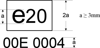
The above certification mark affixed to an engine shows that the type concerned has been certified in Poland (e20), pursuant to this Regulation. The first two digits (00) are indicating the sequence number assigned to the latest technical amendment to this Regulation. The following letter indicates that the certificate was granted for an engine (E). The last four digits (0004) are those allocated by the approval authority to the engine as the base approval number.
1.5In the case that the certification in accordance with this Regulation is granted at the same time as the type approval in accordance with Regulation (EU) No 582/2011, the marking requirements laid down in point 1.4 may follow, separated by ‘/’, the marking requirements laid down in Appendix 8 to Annex I to Regulation (EU) No 582/2011
1.5.1Example of the certification mark (joined marking)

The above certification mark affixed to an engine shows that the type concerned has been certified in Poland (e20), pursuant to Regulation (EU) 582/2011 (Regulation (EU) No 133/2014). The ‘D’ indicates Diesel followed by a ‘C’ for the emission stage. The following two digits (00) are indicating the sequence number assigned to the latest technical amendment to the above mentioned regulation followed by four digits (0004) which are those allocated by the approval authority to the engine as the base approval number for Regulation (EU) 582/2011. After the slash the first two figures are indicating the sequence number assigned to the latest technical amendment to this Regulation, followed by a letter ‘E’ for engine, followed by four digits allocated by the approval authority for the purpose of certification in accordance with this Regulation (‘base approval number’ to this regulation).
1.6.On request of the applicant for certification and after prior agreement with the approval authority other type sizes than indicated in point 1.4.1 and 1.5.1 may be used. Those other type sizes shall remain clearly legible.
1.7.The markings, labels, plates or stickers must be durable for the useful life of the engine and must be clearly legible and indelible. The manufacturer shall ensure that the markings, labels, plates or sticker cannot be removed without destroying or defacing them.
2Numbering
2.1Certification number for engines shall comprise the following:
eX*YYY/YYYY*ZZZ/ZZZZ*E*0000*00
| section 1 | section 2 | section 3 | Additional letter to section 3 | section 4 | section 5 |
|---|---|---|---|---|---|
| Indication of country issuing the certification | CO2 certification act (…/2017) | Latest amending act (zzz/zzzz) | E - engine | Base certification number 0000 | Extension 00 |
Appendix 7 Input parameters for the simulation tool
Introduction
This Appendix describes the list of parameters to be provided by the component manufacturer as input to the simulation tool. The applicable XML schema as well as example data are available at the dedicated electronic distribution platform.
The XML is automatically generated by the engine pre-processing tool.
Definitions
(1) ‘Parameter ID’:
Unique identifier as used in ‘Vehicle Energy Consumption calculation Tool’ for a specific input parameter or set of input data
(2) ‘Type’:
Data type of the parameter
string …
sequence of characters in ISO8859-1 encoding
token …
sequence of characters in ISO8859-1 encoding, no leading/trailing whitespace
date …
date and time in UTC time in the format: YYYY-MM-DDTHH:MM:SSZ with italic letters denoting fixed characters e.g. ‘2002-05-30T09:30:10Z’
integer …
value with an integral data type, no leading zeros, e.g. ‘1800’
double, X …
fractional number with exactly X digits after the decimal sign (‘.’) and no leading zeros e.g. for ‘double, 2’: ‘2345.67’; for ‘double, 4’: ‘45.6780’
(3) ‘Unit’ …
physical unit of the parameter
Set of input parameters
Table 1
Input parameters ‘Engine/General’
| Parameter name | Parameter ID | Type | Unit | Description/Reference |
|---|---|---|---|---|
| Manufacturer | P200 | token | [-] | |
| Model | P201 | token | [-] | |
| TechnicalReportId | P202 | token | [-] | |
| Date | P203 | dateTime | [-] | Date and time when the component-hash is created |
| AppVersion | P204 | token | [-] | Version number of engine pre-processing tool |
| Displacement | P061 | int | [cm3] | |
| IdlingSpeed | P063 | int | [1/min] | |
| RatedSpeed | P249 | int | [1/min] | |
| RatedPower | P250 | int | [W] | |
| MaxEngineTorque | P259 | int | [Nm] | |
| WHTCUrban | P109 | double, 4 | [-] | |
| WHTCRural | P110 | double, 4 | [-] | |
| WHTCMotorway | P111 | double, 4 | [-] | |
| BFColdHot | P159 | double, 4 | [-] | |
| CFRegPer | P192 | double, 4 | [-] | |
| CFNCV | P260 | double, 4 | [-] | |
| FuelType | P193 | string | [-] | Allowed values: ‘Diesel CI’, ‘Ethanol CI’, ‘Petrol PI’, ‘Ethanol PI’, ‘LPG’, ‘NG’ |
Table 2
Input parameters ‘Engine/FullloadCurve’ for each grid point in the full load curve
| Parameter name | Parameter ID | Type | Unit | Description/Reference |
|---|---|---|---|---|
| EngineSpeed | P068 | double, 2 | [1/min] | |
| MaxTorque | P069 | double, 2 | [Nm] | |
| DragTorque | P070 | double, 2 | [Nm] |
Table 3
Input parameters ‘Engine/FuelMap’ for each grid point in the fuel map
| Parameter name | Parameter ID | Type | Unit | Description/Reference |
|---|---|---|---|---|
| EngineSpeed | P072 | double, 2 | [1/min] | |
| Torque | P073 | double, 2 | [Nm] | |
| FuelConsumption | P074 | double, 2 | [g/h] |
Appendix 8 Important evaluation steps and equations of the engine pre-processing tool
This Appendix describes the most important evaluation steps and underlying basic equations that are performed by the engine pre-processing tool. The following steps are performed during evaluation of the input data in the order listed:
1.Reading of input files and automatic check of input data
1.1Check of requirements for input data according to the definitions in paragraph 6.1 of this Annex
1.2Check of requirements for recorded FCMC data according to the definitions in paragraph 4.3.5.2 and subpoint (1) of paragraph 4.3.5.5 of this Annex
2.Calculation of characteristic engine speeds from full load curves of parent engine and actual engine for certification according to the definitions in paragraph 4.3.5.2.1 of this Annex
3.Processing of fuel consumption (FC) map
3.1FC values at nidle are copied to engine speed (nidle – 100 min– 1) in the map
3.2FC values at n95h are copied to engine speed (n95h + 500 min– 1) in the map
3.3Extrapolation of FC values at all engine speed setpoints to a torque value of (1.1 times Tmax_overall) by using least squares linear regression based on the 3 measured FC points with the highest torque values at each engine speed setpoint in the map
3.4Adding of FC = 0 for interpolated motoring torque values at all engine speed setpoints in the map
3.5Adding of FC = 0 for minimum of interpolated motoring torque values from subpoint (3.4) minus 100 Nm at all engine speed setpoints in the map
4.Simulation of FC and cycle work over WHTC and respective subparts for actual engine for certification
4.1.WHTC reference points are denormalized using the full load curve input in originally recorded resolution
4.2.FC is calculated for WHTC denormalized reference values for engine speed and torque from subpoint 4.1
4.3.FC is calculated with engine inertia set to 0
4.4.FC is calculated with standard PT1-function (as in main vehicle simulation) for engine torque response active
4.5.FC for all motoring points is set to 0
4.6.FC for all non-motoring engine operation points is calculated from FC map by Delaunay interpolation method (as in main vehicle simulation)
4.7.Cycle work and FC are calculated according to equations defined in paragraphs 5.1 and 5.2 of this Annex
4.8.Simulated specific FC values are calculated analogous to equations defined in paragraphs 5.3.1 and 5.3.2 of this Annex for measured values
5.Calculation of WHTC correction factors
5.1.Measured values from input to pre-processing tool and simulated values from point (4) are used in accordance with the equations in points (5.2) to (5.4)
5.2.CFUrban = SFCmeas,Urban/SFCsimu,Urban
5.3.CFRural = SFCmeas,Rural/SFCsimu,Rural
5.4.CFMW = SFCmeas,MW/SFCsimu,MW
5.5.In case that the calculated value for a correction factor is lower than 1, the respective correction factor is set to 1
6.Calculation of cold-hot emission balancing factor
6.1.This factor is calculated in accordance with the equation in point (6.2)
6.2.BFcold-hot = 1 + 0,1 × (SFCmeas,cold – SFCmeas,hot)/SFCmeas,hot
6.3.In case that the calculated value for this factor is lower than 1, the factor is set to 1
7.Correction of FC values in FC map to standard NCV
7.1.This correction is performed in accordance with the equation in point (7.2)
7.2.FCcorrected = FCmeasured,map × NCVmeas/NVCstd
7.3.FCmeasured,map shall be the FC value in the FC map input data processed in accordance with point (3)
7.4.NCVmeas and NVCstd shall be defined in accordance with paragraph 5.3.3.1 of this Annex
7.5.In the case that reference fuel of the type B7 (Diesel / CI) in accordance with paragraph 3.2 of this Annex was used during testing, the correction in accordance with points (7.1) to (7.4) is not performed.
8.Converting of engine full load and motoring torque values of the actual engine for certification to a logging frequency of the engine speed of 8 min– 1
8.1.The conversion is performed by arithmetical averaging over intervals of ± 4 min– 1 of the given setpoint for the output data based on the full load curve input in originally recorded resolution
(1)
Specify the tolerance; to be within ± 3 % of the values declared by the manufacturer.
Options/Help
Print Options
PrintThe Whole Regulation
PrintThis Annex only
You have chosen to open the Whole Regulation
The Whole Regulation you have selected contains over 200 provisions and might take some time to download. You may also experience some issues with your browser, such as an alert box that a script is taking a long time to run.
Would you like to continue?
You have chosen to open Schedules only
The Schedules you have selected contains over 200 provisions and might take some time to download. You may also experience some issues with your browser, such as an alert box that a script is taking a long time to run.
Would you like to continue?
Legislation is available in different versions:
Latest Available (revised):The latest available updated version of the legislation incorporating changes made by subsequent legislation and applied by our editorial team. Changes we have not yet applied to the text, can be found in the ‘Changes to Legislation’ area.
Original (As adopted by EU): The original version of the legislation as it stood when it was first adopted in the EU. No changes have been applied to the text.
Opening Options
Different options to open legislation in order to view more content on screen at once
More Resources
Access essential accompanying documents and information for this legislation item from this tab. Dependent on the legislation item being viewed this may include:
- the original print PDF of the as adopted version that was used for the EU Official Journal
- lists of changes made by and/or affecting this legislation item
- all formats of all associated documents
- correction slips
- links to related legislation and further information resources
More Resources
Use this menu to access essential accompanying documents and information for this legislation item. Dependent on the legislation item being viewed this may include:
- the original print PDF of the as adopted version that was used for the print copy
- correction slips
Click 'View More' or select 'More Resources' tab for additional information including:
- lists of changes made by and/or affecting this legislation item
- confers power and blanket amendment details
- all formats of all associated documents
- links to related legislation and further information resources
 All content is available under the Open Government Licence v3.0 except where otherwise stated. This site additionally contains content derived from EUR-Lex, reused under the terms of the Commission Decision 2011/833/EU on the reuse of documents from the EU institutions. For more information see the EUR-Lex public statement on re-use.