- Latest available (Revised)
- Original (As adopted by EU)
Commission Regulation (EU) 2017/2400Show full title
Commission Regulation (EU) 2017/2400 of 12 December 2017 implementing Regulation (EC) No 595/2009 of the European Parliament and of the Council as regards the determination of the CO2 emissions and fuel consumption of heavy-duty vehicles and amending Directive 2007/46/EC of the European Parliament and of the Council and Commission Regulation (EU) No 582/2011 (Text with EEA relevance)
You are here:

What Version
More Resources
Revised version PDFs
- Revised 01/09/20203.68 MB
- Revised 01/03/20193.55 MB
Legislation originating from the EU
When the UK left the EU, legislation.gov.uk published EU legislation that had been published by the EU up to IP completion day (31 December 2020 11.00 p.m.). On legislation.gov.uk, these items of legislation are kept up-to-date with any amendments made by the UK since then.


This item of legislation originated from the EU
Legislation.gov.uk publishes the UK version. EUR-Lex publishes the EU version. The EU Exit Web Archive holds a snapshot of EUR-Lex’s version from IP completion day (31 December 2020 11.00 p.m.).
Status:
This is the original version as it was originally adopted in the EU.
This legislation may since have been updated - see the latest available (revised) version
3.Testing procedure for transmissions
For testing the losses of a transmission the torque loss map for each individual transmission type shall be measured. Transmissions may be grouped into families with similar or equal CO2-relevant data following the provisions of Appendix 6 to this Annex.
For the determination of the transmission torque losses, the applicant for a certificate shall apply one of the following methods for each single forward gear (crawler gears excluded).
(1)
Option 1: Measurement of the torque independent losses, calculation of the torque dependent losses.
(2)
Option 2: Measurement of the torque independent losses, measurement of the torque loss at maximum torque and interpolation of the torque dependent losses based on a linear model
(3)
Option 3: Measurement of the total torque loss.
3.1Option 1: Measurement of the torque independent losses, calculation of the torque dependent losses.
The torque loss Tl ,in on the input shaft of the transmission shall be calculated by
Tl,in (nin , Tin , gear) = T l,in,min_loss + fT * Tin + floss_corr * Tin + T l,in,min_el + fel_corr * Tin
The correction factor for the torque dependent hydraulic torque losses shall be calculated by

The correction factor for the torque dependent electric torque losses shall be calculated by

The torque loss at the input shaft of the transmission caused by the power consumption of transmission electric auxiliary shall be calculated by

where:
Tl,in
=
Torque loss related to input shaft [Nm]
Tl,in,min_loss
=
Torque independent loss at minimum hydraulic loss level (minimum main pressure, cooling/lubrication flows etc.), measured with free rotating output shaft from testing without load [Nm]
Tl,in,max_loss
=
Torque independent loss at maximum hydraulic loss level (maximum main pressure, cooling/lubrication flows etc.), measured with free rotating output shaft from testing without load [Nm]
floss_corr
=
Loss correction for hydraulic loss level depending on input torque [-]
nin
=
Speed at the transmission input shaft (downstream of torque converter, if applicable) [rpm]
fT
=
Torque loss coefficient = 1 – ηT
Tin
=
Torque at the input shaft [Nm]
ηT
=
Torque dependent efficiency (to be calculated); for a direct gear fT = 0,007 (ηT = 0,993) [-]
fel_corr
=
Loss correction for electric power loss level depending on input torque [-]
Tl,in, el
=
Additional torque loss on input shaft by electric consumers [Nm]
Tl,in,min_el
=
Additional torque loss on input shaft by electric consumers corresponding to minimum electric power [Nm]
Tl,in,max_el
=
Additional torque loss on input shaft by electric consumers corresponding to maximum electric power [Nm]
Pel
=
Electric power consumption of electric consumers in transmission measured during transmission loss testing [W]
Tmax,in
=
Maximum allowed input torque for any forward gear in the transmission [Nm]
3.1.1.The torque dependent losses of a transmission system shall be determined as described in the following:
In case of multiple parallel and nominally equal power flows, e.g., twin countershafts or several planet gearwheels in a planetary gear set, that can be treated as one power flow in this section.
3.1.1.1.For each indirect gear g of common transmissions with a non-split power flow and ordinary, non-planetary gear sets, the following steps shall be performed:
3.1.1.2.For each active gear mesh, the torque dependent efficiency shall be set to constant values of ηm:
external – external gear meshes
:
ηm = 0,986
external – internal gear meshes
:
ηm = 0,993
angle drive gear meshes
:
ηm = 0,97
(Angle drive losses may alternatively be determined by separate testing as described in paragraph 6. of this Annex)
3.1.1.3.The product of these torque dependent efficiencies in active gear meshes shall be multiplied with a torque dependent bearing efficiency ηb = 99,5 %.
3.1.1.4.The total torque dependent efficiency η Tg for the gear g shall be calculated by:
η Tg = η b * η m,1 * η m,2 * […] * η m,n
3.1.1.5.The torque dependent loss coefficient fTg for the gear g shall be calculated by:
fTg = 1 – η Tg
3.1.1.6.The torque dependent loss Tl,inTg on the input shaft for gear g shall be calculated by:
Tl,inTg = fTg * Tin
3.1.1.7.The torque dependent efficiency of the planetary range section in low range state for the special case of transmissions consisting of a countershaft-type main section in series with a planetary range section (with non-rotating ring gearwheel and the planet carrier connected to the output shaft) may, alternatively to the procedure described in 3.1.1.8., be calculated by:

where:
ηm,ring
=
Torque dependent efficiency of the ring-to-planet gear mesh = 99,3 % [-]
ηm,sun
=
Torque dependent efficiency of the planet-to-sun gear mesh = 98,6 % [-]
zsun
=
Number of teeth of the sun gearwheel of the range section [-]
zring
=
Number of teeth of the ring gearwheel of the range section [-]
The planetary range section shall be regarded as an additional gear mesh within the countershaft main section, and its torque dependent efficiency ηlowrange shall be included in the determination of the total torque dependent efficiencies ηTg for the low-range gears in the calculation in 3.1.1.4.
3.1.1.8.For all other transmission types with more complex split power flows and/or planetary gear sets (e.g. a conventional automatic planetary transmission), the following simplified method shall be used to determine the torque dependent efficiency. The method covers transmission systems composed of ordinary, non-planetary gear sets and/or planetary gear sets of ring-planet-sun type. Alternatively the torque dependent efficiency may be calculated based on VDI Regulation No. 2157. Both calculations shall use the same constant gear mesh efficiency values defined in 3.1.1.2.
In this case, for each indirect gear g, the following steps shall be performed:
3.1.1.9.Assuming 1 rad/s of input speed and 1 Nm of input torque, a table of speed (Ni ) and torque (Ti ) values for all gearwheels with a fix rotational axis (sun gearwheels, ring gearwheels and ordinary gearwheels) and planet carriers shall be created. Speed and torque values shall follow the right-hand rule, with engine rotation as the positive direction.
3.1.1.10.For each planetary gear set, the relative speeds sun-to-carrier and ring-to-carrier shall be calculated by:
Nsun–carrier = Nsun – Ncarrier
Nring–carrier = Nring – Ncarrier
where:
Nsun
=
Rotational speed of sun gearwheel [rad/s]
Nring
=
Rotational speed of ring gearwheel [rad/s]
Ncarrier
=
Rotational speed of carrier [rad/s]
3.1.1.11.The loss-producing powers in the gear meshes shall be computed in the following way:
For each ordinary, non-planetary gear set, the power P shall be calculated by:
P 1 = N 1 · T 1
P 2 = N 2 · T 2
where:
P=
Power of gear mesh [W]
N=
Rotational speed of gearwheel [rad/s]
T=
Torque of gearwheel [Nm]
For each planetary gear set, the virtual power of sun Pv,sun and ring gearwheels Pv,ring shall be calculated by:
Pv,sun = Tsun · (Nsun – Ncarrier ) = Tsun · Nsun/carrier
Pv,ring = Tring · (Nring – Ncarrier ) = Tring · Nring/carrier
where:
Pv,sun=
Virtual power of sun gearwheel [W]
Pv,ring=
Virtual power of ring gearwheel [W]
Tsun=
Torque of sun gearwheel [Nm]
Tcarrier=
Torque of carrier [Nm]
Tring=
Torque of ring gearwheel [Nm]
Negative virtual power results shall indicate power leaving the gear set, positive virtual power results shall indicate power going into the gear set.
The loss-adjusted powers Padj of the gear meshes shall be computed in the following way:
For each ordinary, non-planetary gear set, the negative power shall be multiplied by the appropriate torque dependent efficiency ηm :
Pi > 0⇒Pi,adj = Pi
Pi < 0⇒Pi,adj = Pi · η mi
where:
Padj=
Loss-adjusted powers of the gear meshes [W]
ηm=
Torque dependent efficiency (appropriate to gear mesh; see 3.1.1.2.) [-]
For each planetary gear set, the negative virtual power shall be multiplied by the torque-dependent efficiencies of sun-to-planet ηmsun and ring-to-planet ηmring :
Pv,i ≥ 0⇒Pi,adj = Pv,i
Pv,i < 0⇒Pi,adj = Pi · ηmsun · ηmring
where:
ηmsun=
Torque dependent efficiency of sun-to-planet [-]
ηmring=
Torque dependent efficiency of ring-to-planet [-]
3.1.1.12.All loss-adjusted power values shall be added up to the torque dependent gear mesh power loss Pm,loss of the transmission system referring to the input power:
Pm,loss = ΣPi,adj
where:
i
=
All gearwheels with a fix rotational axis [-]
Pm,loss
=
Torque dependent gear mesh power loss of the transmission system [W]
3.1.1.13.The torque dependent loss coefficient for bearings,
fT,bear = 1 – η bear = 1 – 0,995 = 0,005
and the torque dependent loss coefficient for the gear mesh

shall be added to receive the total torque dependent loss coefficient fT for the transmission system:
fT = fT,gearmesh + fT,bear
where:
fT
=
Total torque dependent loss coefficient for the transmission system [-]
fT,bear
=
Torque dependent loss coefficient for the bearings [-]
fT,gearmesh
=
Torque dependent loss coefficient for the gear meshes [-]
Pin
=
Fixed input power of the transmission; Pin = (1 Nm * 1 rad/s) [W]
3.1.1.14.The torque dependent losses on the input shaft for the specific gear shall be calculated by:
Tl,inT = fT * Tin
where:
Tl,inT
=
Torque dependent loss related to input shaft [Nm]
Tin
=
Torque at the input shaft [Nm]
3.1.2.The torque independent losses shall be measured in accordance with the procedure described in the following.
3.1.2.1.General requirements
The transmission used for the measurements shall be in accordance with the drawing specifications for series production transmissions and shall be new.
Modifications to the transmission to meet the testing requirements of this Annex, e.g. for the inclusion of measurement sensors or adaption of an external oil conditioning system are permitted.
The tolerance limits in this paragraph refer to measurement values without sensor uncertainty.
Total tested time per transmission individual and gear shall not exceed 2,5 times the actual testing time per gear (allowing re-testing of transmission if needed due to measuring or rig error).
The same transmission individual may be used for a maximum of 10 different tests, e.g. for tests of transmission torque losses for variants with and without retarder (with different temperature requirements) or with different oils. If the same transmission individual is used for tests of different oils, the recommended factory fill oil shall be tested first.
It is not permitted to run a certain test multiple times to choose a test series with the lowest results.
Upon request of the approval authority the applicant for a certificate shall specify and prove the conformity with the requirements defined in this Annex.
3.1.2.2.Differential measurements
To subtract influences caused by the test rig setup (e.g. bearings, clutches) from the measured torque losses, differential measurements are permitted to determine these parasitic torques. The measurements shall be performed at the same speed steps and same test rig bearing temperature(s) ± 3 K used for the testing. The torque sensor measurement uncertainty shall be below 0,3 Nm.
3.1.2.3.Run-in
On request of the applicant a run-in procedure may be applied to the transmission. The following provisions shall apply for a run-in procedure.
3.1.2.3.1.The procedure shall not exceed 30 hours per gear and 100 hours in total.
3.1.2.3.2.The application of the input torque shall be limited to 100 % of maximum input torque.
3.1.2.3.3.The maximum input speed shall be limited by the specified maximum speed for the transmission.
3.1.2.3.4.The speed and torque profile for the run-in procedure shall be specified by the manufacturer.
3.1.2.3.5.The run-in procedure shall be documented by the manufacturer with regard to run-time, speed, torque and oil temperature and reported to the Approval authority.
3.1.2.3.6.The requirements for the ambient temperature (3.1.2.5.1.), measurement accuracy (3.1.4.), test set-up (3.1.8.) and installation angle (3.1.3.2) shall not apply for the run-in procedure.
3.1.2.4.Pre-conditioning
3.1.2.4.1.Pre-conditioning of the transmission and the test rig equipment to achieve correct and stable temperatures before the run-in and testing procedures is allowed.
3.1.2.4.2.The pre-conditioning shall be performed on the direct drive gear without applied torque to the output shaft. If the transmission is not equipped with a direct drive gear, the gear with the ratio closest to 1:1 shall be used.
3.1.2.4.3.The maximum input speed shall be limited by the specified maximum speed for the transmission.
3.1.2.4.4.The maximum combined time for the pre-conditioning shall not exceed 50 hours in total for one transmission. Since the complete testing of a transmission may be divided into multiple test sequences (e.g. each gear tested with a separate sequence), the pre-conditioning may be split into several sequences. Each of the single pre-conditioning sequences shall not exceed 60 minutes.
3.1.2.4.5.The pre-conditioning time shall not be accounted to the time span allocated for the run-in or test procedures.
3.1.2.5.Test conditions
3.1.2.5.1.Ambient temperature
The ambient temperature during the test shall be in a range of 25 °C ± 10 K.
The ambient temperature shall be measured 1 m laterally from the transmission.
The ambient temperature limit shall not apply for the run-in procedure.
3.1.2.5.2.Oil temperature
Except for the oil, no external heating is allowed.
During measurement (except stabilization) the following temperature limits shall apply:
For SMT/AMT/DCT transmissions, the drain plug oil temperature shall not exceed 83 °C when measuring without retarder and 87 °C with retarder mounted to the transmission. If measurements of a transmission without retarder are to be combined with separate measurements of a retarder, the lower temperature limit shall apply to compensate for the retarder drive mechanism and step-up gear and for the clutch in case of a disengageable retarder.
For torque converter planetary transmissions and for transmissions having more than two friction clutches, the drain plug oil temperature shall not exceed 93 °C without retarder and 97 °C with retarder.
To apply the above defined increased temperature limits for testing with retarder, the retarder shall be integrated in the transmission or have an integrated cooling or oil system with the transmission.
During the run-in, the same oil temperature specifications as for regular testing shall apply.
Exceptional oil temperature peaks up to 110 °C are allowed for the following conditions:
(1)
during run-in procedure up to maximum of 10 % of the applied run-in time,
(2)
during stabilization time.
The oil temperature shall be measured at the drain plug or in the oil sump.
3.1.2.5.3.Oil quality
New, recommended first fill oil for the European market shall be used in the test. The same oil fill may be used for run-in and torque measurement.
3.1.2.5.4.Oil viscosity
If multiple oils are recommended for first fill, they are considered to be equal if the oils have a kinematic viscosity within 10 % of each other at the same temperature (within the specified tolerance band for KV100). Any oil with lower viscosity than the oil used in the test shall be considered to result in lower losses for the tests performed within this option. Any additional first fill oil must fall either in the 10 % tolerance band or have lower viscosity than the oil in the test to be covered by the same certificate.
3.1.2.5.5.Oil level and conditioning
The oil level shall meet the nominal specifications for the transmission.
If an external oil conditioning system is used, the oil inside the transmission shall be kept to the specified volume that corresponds to the specified oil level.
To guarantee that the external oil conditioning system is not influencing the test, one test point shall be measured with the conditioning system both on and off. The deviation between the two measurements of the torque loss (= input torque) shall be less than 5 %. The test point is specified as follows:
(1)
gear = highest indirect gear,
(2)
input speed = 1 600 rpm,
(3)
temperatures as specified under 3.1.2.5.
For transmissions with hydraulic pressure control or a smart lubrication system, the measurement of torque independent losses shall be performed with two different settings: first with the transmission system pressure set to at least the minimum value for conditions with engaged gear and a second time with the maximum possible hydraulic pressure (see 3.1.6.3.1).
3.1.3.Installation
3.1.3.1.The electric machine and the torque sensor shall be mounted to the input side of the transmission. The output shaft shall rotate freely.
3.1.3.2.The installation of the transmission shall be done with an angle of inclination as for installation in the vehicle according to the homologation drawing ± 1° or at 0° ± 1°.
3.1.3.3.The internal oil pump shall be included in the transmission.
3.1.3.4.If an oil cooler is either optional or required with the transmission, the oil cooler may be excluded in the test or any oil cooler may be used in the test.
3.1.3.5Transmission testing can be done with or without power take-off drive mechanism and/or power take-off. For establishing the power losses of power take-offs and /or power take-off drive mechanism, the values in Annex VII to this regulation are applied. These values assume that the transmission is tested without power take-off drive mechanism and /or power take-off.
3.1.3.6.Measuring the transmission may be performed with or without single dry clutch (with one or two plates) installed. Clutches of any other type shall be installed during the test.
3.1.3.7.The individual influence of parasitic loads shall be calculated for each specific test rig setup and torque sensor as described in 3.1.8.
3.1.4.Measurement equipment
The calibration laboratory facilities shall comply with the requirements of either ISO/TS 16949, ISO 9000 series or ISO/IEC 17025. All laboratory reference measurement equipment, used for calibration and/or verification, shall be traceable to national (international) standards.
3.1.4.1.Torque
The torque sensor measurement uncertainty shall be below 0,3 Nm.
The use of torque sensors with higher measurement uncertainties is allowed if the part of the uncertainty exceeding 0,3 Nm can be calculated and is added to the measured torque loss as described in 3.1.8. Measurement uncertainty.
3.1.4.2.Speed
The uncertainty of the speed sensors shall not exceed ± 1 rpm.
3.1.4.3.Temperature
The uncertainty of the temperature sensors for the measurement of the ambient temperature shall not exceed ± 1,5 K.
The uncertainty of the temperature sensors for the measurement of the oil temperature shall not exceed ± 1,5 K.
3.1.4.4.Pressure
The uncertainty of the pressure sensors shall not exceed 1 % of the maximum measured pressure.
3.1.4.5.Voltage
The uncertainty of the voltmeter shall not exceed 1 % of the maximum measured voltage.
3.1.4.6.Electric current
The uncertainty of the amperemeter shall not exceed 1 % of the maximum measured current.
3.1.5.Measurement signals and data recording
At least the following signals shall be recorded during the measurement:
(1)
Input torques [Nm]
(2)
Input rotational speeds [rpm]
(3)
Ambient temperature [°C]
(4)
Oil temperature [°C]
If the transmission is equipped with a shift and/or clutch system that is controlled by hydraulic pressure or with a mechanically driven smart lubrication system, additionally to be recorded:
(5)
Oil pressure [kPa]
If the transmission is equipped with transmission electric auxiliary, additionally to be recorded:
(6)
Voltage of transmission electric auxiliary [V]
(7)
Current of transmission electric auxiliary [A]
For differential measurements for the compensation of influences caused by the test rig setup, additionally shall be recorded:
(8)
Test rig bearing temperature [°C]
The sampling and recording rate shall be 100 Hz or higher.
A low pass filter shall be applied to reduce measurement errors.
3.1.6.Test procedure
3.1.6.1.Zero torque signal compensation:
The zero-signal of the torque sensor(s) shall be measured. For the measurement the sensor(s) shall be installed in the test rig. The drivetrain of the test rig (input & output) shall be free of load. The measured signal deviation from zero shall be compensated.
3.1.6.2.Speed range:
The torque loss shall be measured for the following speed steps (speed of the input shaft): 600, 900, 1 200, 1 600, 2 000, 2 500, 3 000, […] rpm up to the maximum speed per gear according to the specifications of the transmission or the last speed step before the defined maximum speed.
The speed ramp (time for the change between two speed steps) shall not extend 20 seconds.
3.1.6.3.Measurement sequence:
3.1.6.3.1.
If the transmission is equipped with smart lubrication systems and/or transmission electric auxiliaries, the measurement shall be conducted with two measurement settings of of these systems:
A first measurement sequence (3.1.6.3.2. to 3.1.6.3.4.) shall be performed with the lowest power consumption by hydraulical and electrical systems when operated in the vehicle (low loss level).
The second measurement sequence shall be performed with the systems set to work with the highest possible power consumption when operated in the vehicle (high loss level).
3.1.6.3.2.
The measurements shall be performed beginning with the lowest up to the highest speed.
3.1.6.3.3.
For each speed step a minimum of 5 seconds stabilization time within the temperature limits defined in 3.1.2.5 is required. If needed, the stabilization time may be extended by the manufacturer to maximum 60 seconds. Oil and ambient temperatures shall be recorded during the stabilization.
3.1.6.3.4.
After the stabilization time, the measurement signals listed in 3.1.5. shall be recorded for the test point for 05-15 seconds.
3.1.6.3.5.
Each measurement shall be performed two times per measurement setting.
3.1.7.Measurement validation
3.1.7.1.The arithmetic mean values of torque, speed, (if applicable) voltage and current for the 05-15 seconds measurement shall be calculated for each of the measurements.
3.1.7.2.The averaged speed deviation shall be below ± 5 rpm of the speed set point for each measured point for the complete torque loss series.
3.1.7.3.The mechanical torque losses and (if applicable) electrical power consumption shall be calculated for each of the measurements as followed:
Tloss = Tin
Pel = I * U
It is allowed to subtract influences caused by the test rig setup from the torque losses (3.1.2.2.).
3.1.7.4.The mechanical torque losses and (if applicable) electrical power consumption from the two sets shall be averaged (arithmetic mean values).
3.1.7.5.The deviation between the averaged torque losses of the two measurement points for each setting shall be below ± 5 % of the average or ± 1 Nm, whichever value is larger. Then, the arithmetic average of the two averaged power values shall be taken.
3.1.7.6.If the deviation is higher, the largest averaged torque loss value shall be taken or the test shall be repeated for the gear.
3.1.7.7.The deviation between the averaged electric power consumption (voltage * current) values of the two measurements for each measurement setting shall be below ± 10 % of the average or ± 5 W, whichever value is larger. Then, the arithmetic average of the two averaged power values shall be taken.
3.1.7.8.If the deviation is higher, the set of averaged voltage and current values giving the largest averaged power consumption shall be taken, or the test shall be repeated for the gear.
3.1.8.Measurement uncertainty
The part of the calculated total uncertainty UT,loss exceeding 0,3 Nm shall be added to Tloss for the reported torque loss Tloss,rep . If UT,loss is smaller than 0,3 Nm, then Tloss,rep = Tloss .
Tloss,rep = Tloss + MAX (0, (UT,loss – 0,3 Nm))
The total uncertainty UT,loss of the torque loss shall be calculated based on the following parameters:
(1)
Temperature effect
(2)
Parasitic loads
(3)
Calibration error (incl. sensitivity tolerance, linearity, hysteresis and repeatability)
The total uncertainty of the torque loss (UT,loss ) is based on the uncertainties of the sensors at 95 % confidence level. The calculation shall be done as the square root of the sum of squares (‘Gaussian law of error propagation’).
wpara = senspara * ipara


where:
Tloss
=
Measured torque loss (uncorrected) [Nm]
Tloss,rep
=
Reported torque loss (after uncertainty correction) [Nm]
UT,loss
=
Total expanded uncertainty of torque loss measurement at 95 % confidence level [Nm]
UT,in
=
Uncertainty of input torque loss measurement [Nm]
uTKC
=
Uncertainty by temperature influence on current torque signal [Nm]
wtkc
=
Temperature influence on current torque signal per Kref, declared by sensor manufacturer [%]
uTK0
=
Uncertainty by temperature influence on zero torque signal (related to nominal torque) [Nm]
wtk0
=
Temperature influence on zero torque signal per Kref (related to nominal torque), declared by sensor manufacturer [%]
Kref
=
Reference temperature span for uTKC and uTK0, wtk0 and wtkc, declared by sensor manufacturer [K]
ΔK
=
Difference in sensor temperature between calibration and measurement [K]. If the sensor temperature cannot be measured, a default value of ΔK = 15 K shall be used.
Tc
=
Current/measured torque value at torque sensor [Nm]
Tn
=
Nominal torque value of torque sensor [Nm]
ucal
=
Uncertainty by torque sensor calibration [Nm]
Wcal
=
Relative calibration uncertainty (related to nominal torque) [%]
kcal
=
Calibration advancement factor (if declared by sensor manufacturer, otherwise = 1)
upara
=
Uncertainty by parasitic loads [Nm]
wpara
=
senspara * ipara
Relative influence of forces and bending torques caused by misalignment
senspara
=
Maximum influence of parasitic loads for specific torque sensor declared by sensor manufacturer [%]; if no specific value for parasitic loads is declared by the sensor manufacturer, the value shall be set to 1,0 %
ipara
=
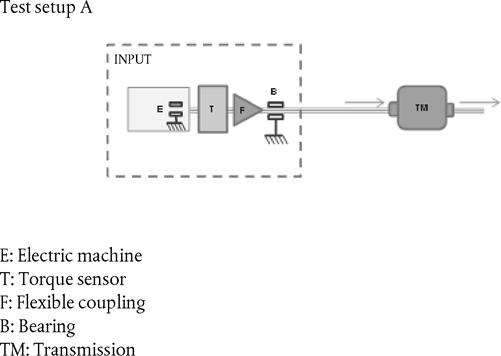
Maximum influence of parasitic loads for specific torque sensor depending on test setup (A/B/C, as defined below).
=
A) 10 % in case of bearings isolating the parasitic forces in front of and behind the sensor and a flexible coupling (or cardan shaft) installed functionally next to the sensor (downstream or upstream); furthermore, these bearings can be integrated in a driving/braking machine (e.g. electric machine) and/or in the transmission as long as the forces in the machine and/or transmission are isolated from the sensor. See figure 1.
=
B) 50 % in case of bearings isolating the parasitic forces in front of and behind the sensor and no flexible coupling installed functionally next to the sensor; furthermore, these bearings can be integrated in a driving/braking machine (e.g. electric machine) and/or in the transmission as long as the forces in the machine and/or transmission are isolated from the sensor. See figure 2.

=
C) 100 % for other setups
3.2.Option 2: Measurement of the torque independent losses, measurement of the torque loss at maximum torque and interpolation of the torque dependent losses based on a linear model
Option 2 describes the determination of the torque loss by a combination of measurements and linear interpolation. Measurements shall be performed for the torque independent losses of the transmission and for one load point of the torque dependent losses (maximum input torque). Based on the torque losses at no load and at maximum input torque, the torque losses for the input torques in between shall be calculated with the torque loss coefficient fTlimo .
The torque loss Tl,in on the input shaft of the transmission shall be calculated by
Tl,in (nin , Tin , gear) = Tl,in,min_loss + fTlimo * Tin + T l,in,min_el + fel_corr * Tin
The torque loss coefficient based on the linear model fTlimo shall be calculated by

where:
Tl,in
=
Torque loss related to input shaft [Nm]
Tl,in,min_loss
=
Drag torque loss at transmission input, measured with free rotating output shaft from testing without load [Nm]
nin
=
Speed at the input shaft [rpm]
fTlimo
=
Torque loss coefficient based on linear model [-]
Tin
=
Torque at the input shaft [Nm]
Tin,maxT
=
Maximum tested torque at the input shaft (normally 100 % input torque, refer to 3.2.5.2. and 3.4.4.) [Nm]
Tl,maxT
=
Torque loss related to input shaft with Tin = Tin,maxT
fel_corr
=
Loss correction for electric power loss level depending on input torque [-]
Tl,in,el
=
Additional torque loss on input shaft by electric consumers [Nm]
Tl,in,min_el
=
Additional torque loss on input shaft by electric consumers corresponding to minimum electric power [Nm]
The correction factor for the torque dependent electric torque losses fel_corr and the torque loss at the input shaft of the transmission caused by the power consumption of transmission electric auxiliary Tl,in,el shall be calculated as described in paragraph 3.1.
3.2.1.The torque losses shall be measured in accordance with the procedure described in the following.
3.2.1.1.General requirements:
As specified for Option 1 in 3.1.2.1.
3.2.1.2.Differential measurements:
As specified for Option 1 in 3.1.2.2.
3.2.1.3.Run-in
As specified for Option 1 in 3.1.2.3.
3.2.1.4.Pre-conditioning
As specified for Option 3 in 3.3.2.1.
3.2.1.5.Test conditions
3.2.1.5.1.Ambient temperature
As specified for Option 1 in 3.1.2.5.1.
3.2.1.5.2.Oil temperature
As specified for Option 1 in 3.1.2.5.2.
3.2.1.5.3.Oil quality / Oil viscosity
As specified for Option 1 in 3.1.2.5.3 and 3.1.2.5.4.
3.2.1.5.4.Oil level and conditioning
As specified for Option 3 in 3.3.3.4.
3.2.2.Installation
As specified for Option 1 in 3.1.3. for the measurement of the torque independent losses.
As specified for Option 3 in 3.3.4. for the measurement of the torque dependent losses.
3.2.3.Measurement equipment
As specified for Option 1 in 3.1.4. for the measurement of the torque independent losses.
As specified for Option 3 in 3.3.5. for the measurement of the torque dependent losses.
3.2.4.Measurement signals and data recording
As specified for Option 1 in 3.1.5 for the measurement of the torque independent losses.
As specified for Option 3 in 3.3.7 for the measurement of the torque dependent losses.
3.2.5.Test procedure
The torque loss map to be applied to the simulation tool contains the torque loss values of a transmission depending on rotational input speed and input torque.
To determine the torque loss map for a transmission, the basic torque loss map data shall be measured and calculated as specified in this paragraph. The torque loss results shall be complemented in accordance with 3.4 and formatted in accordance with Appendix 12 for the further processing by the simulation tool.
3.2.5.1.The torque independent losses shall be determined by the procedure described in 3.1.1. for the torque independent losses for Option 1 only for the low loss level setting of electric and hydraulic consumers.
3.2.5.2.Determine the torque dependent losses for each of the gears using the procedure described for Option 3 in 3.3.6., diverging in the applicable torque range:
Torque range:
The torque losses for each gear shall be measured at 100 % of the maximum transmission input torque per gear.
In the case the output torque exceeds 10 kNm (for a theoretical loss free transmission) or the input power exceeds the specified maximum input power, point 3.4.4. shall apply.
3.2.6.Measurement validation
As specified for Option 3 in 3.3.8.
3.2.7.Measurement uncertainty
As specified for Option 1 in 3.1.8. for the measurement of the torque independent losses.
As specified for Option 3 in 3.3.9. for the measurement of the torque dependent loss.
3.3.Option 3: Measurement of the total torque loss.
Option 3 describes the determination of the torque loss by full measurement of the torque dependent losses including the torque independent losses of the transmission.
3.3.1.General requirements
As specified for Option 1 in 3.1.2.1.
3.3.1.1Differential measurements:
As specified for Option 1 in 3.1.2.2.
3.3.2.Run-in
As specified for Option 1 in 3.1.2.3.
3.3.2.1Pre-conditioning
As specified for Option 1 in 3.1.2.4. with an exception for the following:
The pre-conditioning shall be performed on the direct drive gear without applied torque to the output shaft or target torque on the output shaft set to zero. If the transmission is not equipped with a direct drive gear, the gear with the ratio closest to 1:1 shall be used.
or
The requirements as specified in 3.1.2.4. shall apply, with an exception for the following:
The pre-conditioning shall be performed on the direct drive gear without applied torque to the output shaft or the torque on the output shaft being within +/- 50 Nm. If the transmission is not equipped with a direct drive gear, the gear with the ratio closest to 1:1 shall be used.
or, if the test rig includes a (master friction) clutch at the input shaft:
The requirements as specified in 3.1.2.4. shall apply, with an exception for the following:
The pre-conditioning shall be performed on the direct drive gear without applied torque to the output shaft or without applied torque to the input shaft. If the transmission is not equipped with a direct drive gear, the gear with the ratio closest to 1:1 shall be used.
The transmission would then be driven from the output side. Those proposals could also be combined.
3.3.3.Test conditions
3.3.3.1.Ambient temperature
As specified for Option 1 in 3.1.2.5.1.
3.3.3.2.Oil temperature
As specified for Option 1 in 3.1.2.5.2.
3.3.3.3.Oil quality / Oil viscosity
As specified for Option 1 in 3.1.2.5.3 and 3.1.2.5.4.
3.3.3.4.Oil level and conditioning
The requirements as specified in 3.1.2.5.5. shall apply, diverging in the following:
The test point for the external oil conditioning system is specified as follows:
(1)
highest indirect gear,
(2)
input speed = 1 600 rpm,
(3)
input torque = maximum input torque for the highest indirect gear
3.3.4.Installation
The test rig shall be driven by electric machines (input and output).
Torque sensors shall be installed at the input and output side of the transmission.
Other requirements as specified in 3.1.3. shall apply.
3.3.5.Measurement equipment
For the measurement of the torque independent losses, the measurement equipment requirements as specified for Option 1 in 3.1.4. shall apply.
For the measurement of the torque dependent losses, the following requirements shall apply:
The torque sensor measurement uncertainty shall be below 5 % of the measured torque loss or 1 Nm (whichever value is larger).
The use of torque sensors with higher measurement uncertainties is allowed if the parts of the uncertainty exceeding 5 % or 1 Nm can be calculated and the smaller of those parts is added to the measured torque loss.
The torque measurement uncertainty shall be calculated and included as described under 3.3.9.
Other measurement equipment requirements as specified for Option 1 in 3.1.4. shall apply.
3.3.6.Test procedure
3.3.6.1.Zero torque signal compensation:
As specified in 3.1.6.1.
3.3.6.2.Speed range
The torque loss shall be measured for the following speed steps (speed of the input shaft): 600, 900, 1 200, 1 600, 2 000, 2 500, 3 000, […] rpm up to the maximum speed per gear according to the specifications of the transmission or the last speed step before the defined maximum speed.
The speed ramp (time for the change between two speed steps) shall not exceed 20 seconds.
3.3.6.3.Torque range
For each speed step the torque loss shall be measured for the following input torques: 0 (free rotating output shaft), 200, 400, 600, 900, 1 200, 1 600, 2 000, 2 500, 3 000, 3 500, 4 000, […] Nm up to the maximum input torque per gear according to the specifications of the transmission or the last torque step before the defined maximum torque and/or the last torque step before the output torque of 10 kNm.
In the case the output torque exceeds 10 kNm (for a theoretical loss free transmission) or the input power exceeds the specified maximum input power, point 3.4.4. shall apply.
The torque ramp (time for the change between two torque steps) shall not exceed 15 seconds (180 seconds for option 2).
To cover the complete torque range of a transmission in the above defined map, different torque sensors with limited measurement ranges may be used on the input/output side. Therefore the measurement may be divided into sections using the same set of torque sensors. The overall torque loss map shall be composed of these measurement sections.
3.3.6.4.Measurement sequence
3.3.6.4.1.The measurements shall be performed beginning with the lowest up to the highest speed.
3.3.6.4.2.The input torque shall be varied according to the above defined torque steps from the lowest to the highest torque which is covered by the current torque sensors for each speed step.
3.3.6.4.3.For each speed and torque step a minimum of 5 seconds stabilization time within the temperature limits defined in 3.3.3. is required. If needed, the stabilization time may be extended by the manufacturer to maximum 60 seconds (maximum 180 seconds for option 2). Oil and ambient temperatures shall be recorded during the stabilization.
3.3.6.4.4.The measurement set shall be performed two times in total. For that purpose, sequenced repetition of sections using the same set of torque sensors is allowed.
3.3.7.Measurement signals and data recording
At least the following signals shall be recorded during the measurement:
(1)
Input and output torques [Nm]
(2)
Input and output rotational speeds [rpm]
(3)
Ambient temperature [°C]
(4)
Oil temperature [°C]
If the transmission is equipped with a shift and/or clutch system that is controlled by hydraulic pressure or with a mechanically driven smart lubrication system, additionally to be recorded:
(5)
Oil pressure [kPa]
If the transmission is equipped with transmission electric auxiliary, additionally to be recorded:
(6)
Voltage of transmission electric auxiliary [V]
(7)
Current of transmission electric auxiliary [A]
For differential measurements for compensation of influences by test rig setup, additionally to be recorded:
(8)
Test rig bearing temperature [°C]
The sampling and recording rate shall be 100 Hz or higher.
A low pass filter shall be applied to avoid measurement errors.
3.3.8.Measurement validation
3.3.8.1.The arithmetic mean values of torque, speed, if applicable voltage and current for the 05-15 seconds measurement shall be calculated for each of the two measurements.
3.3.8.2.The measured and averaged speed at the input shaft shall be below ± 5 rpm of the speed set point for each measured operating point for the complete torque loss series. The measured and averaged torque at the input shaft shall be below ± 5 Nm or ± 5 % of the torque set point whichever value is larger for each measured operating point for the complete torque loss series.
3.3.8.3.The mechanical torque losses and (if applicable) electrical power consumption shall be calculated for each of the measurements as followed:
Pel = I * U

It is allowed to subtract influences caused by the test rig setup from the torque losses (3.3.2.2.).
3.3.8.4.The mechanical torque losses and (if applicable) electrical power consumption from the two sets shall be averaged (arithmetic mean values).
3.3.8.5.The deviation between the averaged torque losses of the two measurement sets shall be below ± 5 % of the average or ± 1 Nm (whichever value is larger). The arithmetic average of the two averaged torque loss values shall be taken. If the deviation is higher, the largest averaged torque loss value shall be taken or the test shall be repeated for the gear.
3.3.8.6.The deviation between the averaged electric power consumption (voltage*current) values of the two measurement sets shall be below ± 10 % of the average or ± 5 W, whichever value is larger. Then, the arithmetic average of the two averaged power values shall be taken.
3.3.8.7.If the deviation is higher, the set of averaged voltage and current values giving the largest averaged power consumption shall be taken, or the test shall be repeated for the gear.
3.3.9.Measurement uncertainty
The part of the calculated total uncertainty UT,loss exceeding 5 % of Tloss or 1 Nm (ΔUT,loss ), whichever value of ΔUT,loss is smaller, shall be added to Tloss for the reported torque loss Tloss,rep . If UT,loss is smaller than 5 % of Tloss or 1 Nm, then Tloss,rep = Tloss .
Tloss,rep = Tloss + MAX (0, ΔUT,loss )
ΔUT,loss = MIN ((UT,loss – 5 % * Tloss ), (UT,loss – 1 Nm))
For each measurement set, the total uncertainty UT,loss of the torque loss shall be calculated based on the following parameters:
(1)
Temperature effect
(2)
Parasitic loads
(3)
Calibration error (incl. sensitivity tolerance, linearity, hysteresis and repeatability)
The total uncertainty of the torque loss (UT,loss ) is based on the uncertainties of the sensors at 95 % confidence level. The calculation shall be done as the square root of the sum of squares (‘Gaussian law of error propagation’).
wpara = senspara * ipara


where:
Tloss
=
Measured torque loss (uncorrected) [Nm]
Tloss,rep
=
Reported torque loss (after uncertainty correction) [Nm]
UT,loss
=
Total expanded uncertainty of torque loss measurement at 95 % confidence level [Nm]
uT,in/out
=
Uncertainty of input/output torque loss measurement separately for input and output torque sensor[Nm]
igear
=
Gear ratio [-]
uTKC
=
Uncertainty by temperature influence on current torque signal [Nm]
wtkc
=
Temperature influence on current torque signal per Kref, declared by sensor manufacturer [%]
uTK0
=
Uncertainty by temperature influence on zero torque signal (related to nominal torque) [Nm]
wtk0
=
Temperature influence on zero torque signal per Kref (related to nominal torque), declared by sensor manufacturer [%]
Kref
=
Reference temperature span for uTKC and uTK0, wtk0 and wtkc, declared by sensor manufacturer [K]
ΔK
=
Difference in sensor temperature between calibration and measurement [K]. If the sensor temperature cannot be measured, a default value of ΔK = 15 K shall be used.
Tc
=
Current/measured torque value at torque sensor [Nm]
Tn
=
Nominal torque value of torque sensor [Nm]
ucal
=
Uncertainty by torque sensor calibration [Nm]
Wcal
=
Relative calibration uncertainty (related to nominal torque) [%]
kcal
=
calibration advancement factor (if declared by sensor manufacturer, otherwise = 1)
upara
=
Uncertainty by parasitic loads [Nm]
wpara
=
senspara * ipara
Relative influence of forces and bending torques caused by misalignment [%]
senspara
=
Maximum influence of parasitic loads for specific torque sensor declared by sensor manufacturer [%]; if no specific value for parasitic loads is declared by the sensor manufacturer, the value shall be set to 1,0 %
ipara
=
Maximum influence of parasitic loads for specific torque sensor depending on test setup (A/B/C, as defined below).
=
A) 10 % in case of bearings isolating the parasitic forces in front of and behind the sensor and a flexible coupling (or cardan shaft) installed functionally next to the sensor (downstream or upstream); furthermore, these bearings can be integrated in a driving/braking machine (e.g. electric machine) and/or in the transmission as long as the forces in the machine and/or transmission are isolated from the sensor. See figure 3.

=
B) 50 % in case of bearings isolating the parasitic forces in front of and behind the sensor and no flexible coupling installed functionally next to the sensor; furthermore, these bearings can be integrated in a driving/braking machine (e.g. electric machine) and/or in the transmission as long as the forces in the machine and/or transmission are isolated from the sensor. See figure 4.

=
C) 100 % for other setups
3.4.Complement of input files for the simulation tool
For each gear a torque loss map covering the defined input speed and input torque steps shall be determined with one of the specified testing options or standard torque loss values. For the input file for the simulation tool, this basic torque loss map shall be complemented as described in the following:
3.4.1.In the cases the highest tested input speed was the last speed step below the defined maximum permissible transmission speed, an extrapolation of the torque loss shall be applied up to the maximum speed with linear regression based on the two last measured speed steps.
3.4.2.In the cases the highest tested input torque was the last torque step below the defined maximum permissible transmission torque, an extrapolation of the torque loss shall be applied up to the maximum torque with linear regression based on the two last measured torque steps for the corresponding speed step. In order to handle engine torque tolerances, etc., the simulation tool will, if required, perform an extrapolation of the torque loss for input torques up to 10 % above said defined maximum permissible transmission torque.
3.4.3.In the case of extrapolation of the torque loss values for maximum input speed and maximum input torque at the same time, the torque loss for the combined point of highest speed and highest torque shall be calculated with two-dimensional linear extrapolation.
3.4.4.If the maximum output torque exceeds 10 kNm (for a theoretical loss free transmission), and/or for all speed and torque points with input power higher than the specified maximum input power, the manufacturer may choose to take the torque loss values for all torques higher than 10 kNm, and/or for all speed and torque points with input power higher than the specified maximum input power, respectively, from one of:
(1)
Calculated fallback values (Appendix 8)
(2)
Option 1
(3)
Option 2 or 3 in combination with a torque sensor for higher output torques (if required)
For cases (i) and (ii) in Option 2, the torque losses at load shall be measured at the input torque that corresponds to output torque 10 kNm and/or the specified maximum input power.
3.4.5.For speeds below the defined minimum speed and the additional input speed step of 0 rpm, the reported torque losses determined for the minimum speed step shall be copied.
3.4.6.To cover the range of negative input torques during vehicle coasting conditions, the torque loss values for positive input torques shall be copied for the related negative input torques.
3.4.7.Upon agreement of an approval authority, the torque losses for the input speeds below 1 000 rpm may be replaced by the torque losses at 1 000 rpm when the measurement is technically not possible.
3.4.8.If the measurement of speed points is technically not possible (e.g. due to natural frequency), the manufacturer may, in agreement with the approval authority, calculate the torque losses by interpolation or extrapolation (limited to max. 1 speed step per gear).
3.4.9.The torque loss map data shall be formatted and saved as specified in Appendix 12 to this Annex.
Options/Help
Print Options
PrintThe Whole Regulation
PrintThe Whole Annex
PrintThis Division only
You have chosen to open the Whole Regulation
The Whole Regulation you have selected contains over 200 provisions and might take some time to download. You may also experience some issues with your browser, such as an alert box that a script is taking a long time to run.
Would you like to continue?
You have chosen to open Schedules only
The Schedules you have selected contains over 200 provisions and might take some time to download. You may also experience some issues with your browser, such as an alert box that a script is taking a long time to run.
Would you like to continue?
Legislation is available in different versions:
Latest Available (revised):The latest available updated version of the legislation incorporating changes made by subsequent legislation and applied by our editorial team. Changes we have not yet applied to the text, can be found in the ‘Changes to Legislation’ area.
Original (As adopted by EU): The original version of the legislation as it stood when it was first adopted in the EU. No changes have been applied to the text.
Opening Options
Different options to open legislation in order to view more content on screen at once
More Resources
Access essential accompanying documents and information for this legislation item from this tab. Dependent on the legislation item being viewed this may include:
- the original print PDF of the as adopted version that was used for the EU Official Journal
- lists of changes made by and/or affecting this legislation item
- all formats of all associated documents
- correction slips
- links to related legislation and further information resources
More Resources
Use this menu to access essential accompanying documents and information for this legislation item. Dependent on the legislation item being viewed this may include:
- the original print PDF of the as adopted version that was used for the print copy
- correction slips
Click 'View More' or select 'More Resources' tab for additional information including:
- lists of changes made by and/or affecting this legislation item
- confers power and blanket amendment details
- all formats of all associated documents
- links to related legislation and further information resources
 All content is available under the Open Government Licence v3.0 except where otherwise stated. This site additionally contains content derived from EUR-Lex, reused under the terms of the Commission Decision 2011/833/EU on the reuse of documents from the EU institutions. For more information see the EUR-Lex public statement on re-use.