
[F1ANNEX Xa U.K. CONFORMITY OF SIMULATION TOOL OPERATION AND OF CO 2 EMISSIONS AND FUEL CONSUMPTION RELATED PROPERTIES OF COMPONENTS, SEPARATE TECHNICAL UNITS AND SYSTEMS: VERIFICATION TESTING PROCEDURE
Textual Amendments
1. Introduction U.K.
This Annex sets out the requirements for the verification testing procedure which is the test procedure for verifying the CO 2 emissions of new heavy-duty vehicles.
The verification testing procedure consists of an on-road test to verify the CO 2 emissions of new vehicles after production. It shall be carried out by the vehicle manufacturer and verified by the approval authority that granted the licence to operate the simulation tool.
During the verification testing procedure the torque and speed at the driven wheels, the engine speed, the fuel consumption, the engaged gear of the vehicle and the other relevant parameters listed in point 6.1.6 shall be measured. The measured data shall be used as input to the simulation tool, which uses the vehicle-related input data and the input information from the determination of the CO 2 emissions and fuel consumption of the vehicle. For the verification testing procedure simulation, the instantaneously measured wheel torque and the rotational speed of the wheels as well as the engine speed shall be used as input, as described in Figure 1 instead of the vehicle speed, in accordance with point 6.1.6. The fan power during the verification testing procedure shall be calculated in accordance with the measured fan speed. The measured fuel consumption shall be within the tolerances set out in point 7 and compared to the fuel consumption simulated with the verification data set to pass the verification testing procedure.
As part of the verification testing procedure, the correctness of the vehicle input data set from the certification of CO 2 emissions and fuel consumption related properties of the components, separate technical units and systems shall also be reviewed to check the data and the data handling process. The correctness of the input data relating to components, separate technical units and systems relevant for air drag and for rolling resistance of the vehicle shall be verified in accordance with point 6.1.1.
Figure 1 Schematic picture of the verification testing procedure method U.K.

2. Definitions U.K.
For the purposes of this Annex the following definitions shall apply:
‘verification test relevant data set’ means a set of input data for components, separate technical units and systems and input information used for CO 2 determination of a verification testing procedure relevant vehicle;
‘verification testing procedure relevant vehicle’ means a new vehicle for which a value of CO 2 emissions and fuel consumption was determined and declared in accordance with Article 9;
‘ corrected actual mass of the vehicle ’ means the corrected actual mass of the vehicle in accordance with point 2(4) of Annex III;
‘ actual mass of the vehicle ’ is as defined in Article 2(6) of Regulation (EU) No 1230/2012;
‘ actual mass of the vehicle with payload ’ means the actual mass of the vehicle with the superstructure and with the payload applied in the verification testing procedure;
‘ wheel power ’ means the total power at the driven wheels of a vehicle to overcome all driving resistances at the wheel, computed in the simulation tool from the measured torque and rotational speed of the driven wheels;
‘ control area network signal ’ or ‘ CAN signal ’ means a signal from the connection with the vehicle electronic control unit as referred to in paragraph 2.1.5 of Appendix 1 to Annex II to Regulation (EU) No 582/2011;
‘ urban driving ’ means the total distance driven during the fuel consumption measurement at speeds below 50 km/h;
‘ rural driving ’ means the total distance driven during the fuel consumption measurement at speeds from 50 km/h to 70 km/h;
‘ motorway driving ’ means the total distance driven in the fuel consumption measurement at speeds above 70 km/h;
‘crosstalk’ means the signal at the main output of a sensor (M y ), produced by a measurand (F z ) acting on the sensor, which is different from the measurand assigned to this output; the coordinate system assignment is defined in accordance with ISO 4130.
3. Vehicle selection U.K.
The number of new vehicles to be tested per year of production ensures that the relevant variations of components, separate technical units or systems used are covered by the verification testing procedure. The vehicle selection for the verification test shall be based on following requirements:
The vehicles for verification test shall be selected out of the vehicles from the production line for which a value of CO 2 emissions and fuel consumption has been determined and declared in accordance with Article 9. The components, separate technical units or systems mounted in or on the vehicle shall be out of series production and shall correspond to those mounted at production date of the vehicle.
The vehicle selection shall be made by the approval authority that granted the licence to operate the simulation tool based on proposals from the vehicle manufacturer.
Only vehicles with one driven axle shall be selected for verification test.
It is recommended to include in each verification test relevant data set engine, axle and transmission with highest sales numbers per manufacturer. The components, separate technical units or systems may be tested all in one vehicle or in different vehicles, under the condition that each component is covered by minimum one verification test on one vehicle.
Vehicles which use standard values for CO 2 certification of their components, separate technical units or systems instead of measured values for the transmission and for the axle losses shall not be selected for the verification test as long as vehicles complying with the requirements in points a) to c) and using measured loss maps for these components, separate technical units or systems in the CO 2 certification, are produced.
The minimum number of different vehicles with different combinations of verification test relevant data sets to be tested by verification test per year shall be based on the sales numbers of the vehicle manufacturer as set out in Table 1:
| Table 1 | |
| Determination of the minimum number of vehicles to be tested by the vehicle manufacturer | |
| Number of vehicles to be tested | Verification testing procedure relevant vehicles produced/year |
|---|---|
| 1 | 1- 25 000 |
| 2 | 25 001 - 50 000 |
| 3 | 50 001 - 75 000 |
| 4 | 75 001 - 100 000 |
| 5 | more than 100 000 |
The vehicle manufacturer shall finalize the verification test within a period of 10 months after the date of selection of the vehicle for the verification test.
4. Vehicle conditions U.K.
Each vehicle for the verification test shall be in series conditions as typically delivered to the customer. No changes in hardware such as lubricants or in the software such as auxiliary controllers are allowed.
4.1. Vehicle run in U.K.
Run in of the vehicle is not mandatory. If the total mileage of the test vehicle is less than 15 000 km, an evolution coefficient for the test result shall be applied as defined in point 7. The total mileage of the test vehicle shall be the odometer reading at start of the fuel consumption measurement. The maximum mileage for the verification testing procedure shall be 20 000 km.
4.2. Fuel and lubricants U.K.
All lubricants shall be in line with the series configuration of the vehicle.
For the fuel consumption measurement as described in point 6.1.5, reference fuel as set out in point 3.2 of Annex V shall be used.
The fuel tank shall be full at start of the fuel consumption measurement run.
5. Measurement equipment U.K.
All laboratory reference measurement equipment, used for calibration and verification, shall be traceable to national (international) standards. The calibration laboratory shall comply with the requirements of ISO 9000 series and either ISO/TS 16949 or ISO/IEC 17025.
5.1. Torque U.K.
The direct torque at all driven axles shall be measured with one of the following measurement systems fulfilling the requirements listed in Table 2:
hub torque meter;
rim torque meter;
half-shaft torque meter.
The calibrated range shall be at least 10 000 Nm; the measurement range shall cover the entire range of torque occurring during the verification testing procedure of the tested vehicle.
The drift shall be measured during the verification test described in point 6 by zeroing the torque measurement system in accordance with point 6.1.5 after the pre-conditioning phase by lifting the axle and measuring the torque at lifted axle directly after the verification test again.
For a valid test result a maximum drift of the torque measurement system over the verification testing procedure of 150 Nm (sum of both wheels) shall be proven.
5.2. Vehicle speed U.K.
The vehicle speed shall be used for possible plausibility checks of the gear signal later on and shall be based on the CAN signal.
5.3. Gear engaged U.K.
The engaged gear does not need to be measured but shall be calculated by the simulation tool based on measured engine speed, the vehicle speed and the tyre dimensions and transmission ratios of the vehicle in accordance with point 7. The gear position may be provided also from the CAN signal to check possible deviations from the gear position calculated by the simulation tool. In case of deviations of the gear position in more than 5 % of the test duration, the reasons for the deviation shall be investigated and reported by the vehicle manufacturer. The input data on gear position shall be used in the simulation tool to compute the gear dependent losses in the gear box. The engine speed shall be taken by the simulation tool from the input data as defined in point 5.4.
5.4. Rotational speed of the engine U.K.
The signal from the connection with the vehicle electronic control unit via the open on-board diagnostic interface shall be used to measure the engine speed. Alternative measurement systems are allowed if they fulfil the requirements set out in Table 2.
5.5. Rotational speed of the wheels at the driven axle U.K.
The measurement system for the rotational speed of left and right wheel at the driven axle for the assessment of the power demand at the wheels as input to the simulation tool for the verification test simulation shall fulfil the requirements set out in Table 2.
5.6. Rotational speed of fan U.K.
The CAN signal for the fan speed may be used, if available. Alternatively an external sensor fulfilling the requirements set out in Table 2 may be used.
5.7. Fuel measurement system U.K.
The fuel consumed shall be measured on-board with a measurement device reporting the total amount of fuel consumed in kilograms. The fuel measurement system shall be based on one of the following measurement methods:
Measurement of fuel mass. The fuel measuring device shall fulfil the accuracy requirements set out in Table 2 for the fuel mass measurement system.
Measurement of fuel volume together with correction for the thermal expansion of the fuel. The fuel volume measurement device and fuel temperature measurement device shall fulfil the accuracy requirements set out in Table 2 for the fuel volume measurement system. The fuel mass consumed shall be calculated in accordance with the following equations:


where:
=
Calculated fuel mass [kg]
=
Total number of samples in measurement.
=
Density of the fuel used for the verification test in (kg/m 3 ). The density shall be determined in accordance with Annex IX of the Regulation (EU) No 582/2011. If diesel fuel is used in the verification test, also the average value of the density interval for the reference fuels B7 in accordance with Annex IX of the Regulation (EU) No 582/2011 may be used.
=
Fuel temperature that corresponds to density ρ 0 for the reference fuel, as defined in Annex V [°C]
=
Density of the test fuel at sample i [kg/m 3 ]
=
Total fuel volume consumed at sample i [m 3 ]
=
Measured fuel temperature at sample i + 1 [°C]
=
Temperature correction factor (0,001 K – 1 ).
5.8. Vehicle weight U.K.
The following masses of the vehicle shall be measured with equipment fulfilling the requirements set out in Table 2:
actual mass of the vehicle;
actual mass of the vehicle with payload.
5.9. General requirements for the on-board measurements U.K.
All data shall be recorded at least in 2 Hz frequency or at recommended frequency from the equipment maker, whichever is the higher value.
The input data for the simulation tool may be composed from different recorders. The following input data shall be provided from measurements:
torque at the driven wheels per wheel;
rotational speed at the driven wheels per wheel;
gear (optional);
engine speed;
fan speed;
vehicle speed;
fuel flow.
The torque and rotational speed at the wheels shall be recorded in one data-logging system. If different data-logging systems are used for the other signals, one common signal, such as vehicle speed, shall be recorded to ensure correct time alignment of the signals.
The accuracy requirements set out in Table 2 shall be met by all measurement equipment used. Any equipment not listed in Table 2 shall fulfil the accuracy requirements set out in Table 2 of Annex V.
Table 2
Requirements of measurement systems
| a Rise time means the difference in time between the 10 percent and 90 percent response of the final analyser reading (t90 – t10). | ||
| b The accuracy shall be met for the integral fuel flow over 100 minutes. | ||
| Measurement system | Accuracy | Rise time a |
|---|---|---|
| Balance for vehicle weight | 50 kg or < 0,5 % of max. calibration whichever is smaller | — |
| Rotational speed wheels | < 0,5 % of max. calibration | ≤ 1 s |
| Fuel mass flow for liquid fuels | < 1,0 % of reading or < 0,5 % of max. calibration whichever is larger | ≤ 2 s |
| Fuel volume measurement system b | < 1,0 % of reading or < 0,5 % of max. calibration whichever is larger | ≤ 2 s |
| Temperature of the fuel | ± 1 °C | ≤ 2 s |
| Sensor for measuring the rotational speed cooling fan | 0,4 % of reading or 0,2 % of max. calibration of speed whichever is larger | ≤ 1 s |
| Engine speed | As set out in Annex V | |
| Wheel torque | For 10 kNm calibration: < 40 Nm accuracy < 20 Nm crosstalk | < 0,1 s |
The maximum calibration values shall be at least 1,1 times the maximum predicted value expected during all test runs for the respective measurement system. For the torque measurement system the maximum calibration may be limited to 10 kNm.
Accuracy given shall be met by the sum of all single accuracies in the case more than one scale is used.
6. Test procedure U.K.
6.1. Vehicle preparation U.K.
The vehicle shall be taken from the series production and selected as set out in point 3.
6.1.1. Validation of input data U.K.
The manufacturer's records file for the vehicle selected shall be used as basis for validating the input data. The vehicle identification number of the vehicle selected shall be the same as the vehicle identification number in the customer information file.
Upon request by the approval authority that granted the licence to operate the simulation tool, the vehicle manufacturer shall provide, within 15 working days, the manufacturer's records file, the input information and input data necessary to run the simulation tool as well as the certificate of CO 2 emissions and fuel consumption related properties for all relevant components, separate technical units or systems.
6.1.1.1. Verification of components, separate technical units or systems and input data and information U.K.
The following checks shall be performed for the components, separate technical units and systems mounted on the vehicle:
Simulation tool data integrity: the integrity of the cryptographic hash of the manufacturer's records file in accordance with Article 9(3) re-calculated during the verification testing procedure with the hashing tool shall be verified by comparison with the cryptographic hash in the certificate of conformity;
Vehicle data: the vehicle identification number, axle configuration, selected auxiliaries and power take off technology shall match the selected vehicle;
Component, separate technical unit or system data: the certification number and the model type imprinted on the certificate of CO 2 emissions and fuel consumption related properties shall match the component, separate technical unit or system installed in the selected vehicle;
The hash of the simulation tool input data and the input information shall match the hash imprinted on the certificate of CO 2 emissions and fuel consumption related properties for the following components, separate technical units or systems:
engines;
transmissions;
torque converters;
other torque transferring components;
additional driveline components;
axles;
body or trailer air drag;
tyres.
6.1.1.2. Verification of the vehicle mass U.K.
If requested by the approval authority that granted the licence to operate the simulation tool, a verification of the corrected actual mass of the vehicle shall be included into the verification of input data.
For the verification of the mass, the mass in running order of the vehicle shall be verified in accordance with point 2 of Appendix 2 to Annex I to Regulation (EC) No 1230/2012.
6.1.1.3. Actions to be taken U.K.
In case of discrepancies in the certification number or the cryptographic hash of one or more files regarding the components, separate technical units or systems listed in subpoints (d)(i) to (vii) of point 6.1.1.1 the correct input data file fulfilling the checks in accordance with points 6.1.1.1 and 6.1.1.2 shall replace the incorrect data for all further actions. If no complete input data set with correct certificates of CO 2 emissions and fuel consumption related properties is available for the components, separate technical units or systems listed in subpoints (d)(i) to (vii) of point 6.1.1.1 the verification test shall end and the vehicle fails the verification testing procedure.
6.1.2. Run in phase U.K.
After the validation of input data in accordance with point 6.1.1, a run in phase up to maximum 15 000 km odometer reading may take place, with no need to use the reference fuel, if the odometer reading of the vehicle selected is below 15 000 km. In case of damage of any of the components, separate technical units or systems listed in point 6.1.1.1, the component, separate technical units or systems may be replaced by an equivalent component, separate technical units or systems with the same certification number. The replacement shall be documented in the test report.
All relevant components, separate technical units or systems shall be checked before the measurements to exclude unusual conditions, such as incorrect oil fill levels, plugged air filters or on-board diagnostic warnings.
6.1.3. Set up of measurement equipment U.K.
All measurement systems shall be calibrated in accordance with the provisions of the equipment maker. If no provisions exist, the recommendations from the equipment maker shall be followed for calibration.
After the run in phase, the vehicle shall be equipped with the measurement systems set out in point 5.
6.1.4. Set up of the test vehicle for the fuel consumption measurement U.K.
Tractors of the vehicle groups defined in Table 1 of Annex I shall be tested with any type of semitrailer, providing the loading defined below can be applied.
Rigid lorries of the vehicle groups defined in Table 1 of Annex I shall be tested with trailer, if a trailer connection is mounted. Any body type or other device to carry the loading set out below can be applied.
The bodies of the vehicles may differ from the standard bodies set out in Table 1 of Annex I for the certification of CO 2 emissions and fuel consumption related properties of component, separate technical units or systems.
The vehicle payload shall be at minimum to a mass leading to a total test weight of 90 % of the maximum gross combined weight or gross vehicle weight for rigid lorries without trailer.
The tyre inflation pressure shall be in line with the recommendation of the manufacturer. The tyres of the semitrailer may differ from the standard tyres set out in Table 2 of Part B of Annex II to Regulation (EC) No 661/2009 for the CO 2 certification of tyres.
All settings influencing the auxiliary energy demand shall be set to minimum reasonable energy consumption where applicable. The air conditioning shall be switched off and venting of the cabin shall be set lower than medium mass flow. Additional energy consumers not necessary to run the vehicle shall be switched off. External devices to provide energy on board, such as external batteries, are allowed only for running the extra measurement equipment for the verification testing procedure listed in Table 2 but shall not provide energy to serial vehicle equipment.
A particle filter regeneration may be initiated and shall be achieved before the verification test. If an initiated particle filter regeneration cannot be achieved before the verification test, the test is invalid and shall be repeated.
6.1.5. Verification test U.K.
6.1.5.1. Route selection U.K.
The route selected for the verification test shall fulfil the requirements set out in Table 3. The routes may include both public and private tracks.
6.1.5.2. Vehicle pre conditioning U.K.
No specific pre-conditioning of the vehicle is required.
6.1.5.3. Vehicle warm up U.K.
Before the fuel consumption measurement starts, the vehicle shall be driven for warm up as set out in Table 3. The warm up phase shall not be considered in the evaluation of the verification test.
6.1.5.4. Zeroing of the torque measurement equipment U.K.
Zeroing of the torque measurement equipment shall follow the instruction of the equipment maker. It shall be ensured for zeroing, that the torque on the driven axle is zero. For zeroing, the vehicle shall be stopped directly after the warm up phase and zeroing shall be performed directly after the vehicle stop to minimise cool down effects. Zeroing shall be finished within less than 20 minutes.
6.1.5.5. Fuel consumption measurement U.K.
The fuel consumption measurement shall start directly after the zeroing of the wheel-torque measurement equipment at vehicle stand still and engine idling. The vehicle shall be driven during the measurement in a driving style avoiding unnecessary braking of the vehicle, gas pedal pumping and aggressive cornering. The setting for the electronic control systems which is activated automatically at vehicle start shall be used, and gear shifts shall be performed by the automated system if applicable. If only manual settings for the electronic control systems are available, the settings leading to higher fuel consumption per kilometre shall be selected. The duration of the fuel consumption measurement shall be within the tolerances set out in Table 3. The fuel consumption measurement shall end also at vehicle stand still in idling condition directly before the measurement of the drift of the torque measurement equipment.
6.1.5.6. Measurement of the drift of the torque measurement equipment U.K.
Directly after the fuel consumption measurement, the drift of the torque measurement equipment shall be recorded by measuring the torque at the same vehicle conditions as during the zeroing process. If the fuel consumption measurement does not end at zero vehicle speed, the vehicle shall be stopped for the drift measurement in moderate deceleration.
6.1.5.7. Boundary conditions for the verification test U.K.
The boundary conditions to be met for a valid verification test are set in Table 3.
If the vehicle passes the verification test in accordance with point 7, the test shall be set valid even if the following conditions are not met:
undercut of minimum values for parameter No 1, 2, 6, 9 in Table 3,
exceedance of maximum values for parameter No 3, 4, 5, 7, 8, 10, 12 in Table 3.
Table 3
Parameters for a valid verification test
| a Or maximum vehicle speed if lower than 70 km/h | ||||
| No | Parameter | Min. | Max. | Applicable for |
|---|---|---|---|---|
| 1 | Warm up [minutes] | 60 | ||
| 2 | Average velocity at warm up [km/h] | 70 a | 100 | |
| 3 | Fuel consumption measurement duration [minutes] | 80 | 120 | |
| 4 | Distance based share urban driving | 2 % | 8 % | vehicle groups 4, 5, 9, 10 |
| 5 | Distance based share rural driving | 7 % | 13 % | |
| 6 | Distance based share motorway driving | 74 % | — | vehicle groups 4, 5, 9, 10 |
| 7 | Time share of idling at stand still | 5 % | ||
| 8 | Average ambient temperature | 5 °C | 30 °C | |
| 9 | Road condition dry | 100 % | ||
| 10 | Road condition snow or ice | 0 % | ||
| 11 | Seal level of the route [m] | 0 | 800 | |
| 12 | Duration of continuous idling at stand still [minutes] | 3 | ||
In case of extraordinary traffic conditions, the verification test shall be repeated.
6.1.6. Data reporting U.K.
The data recorded during the verification testing procedure shall be reported to the approval authority that granted the licence to operate the simulation tool as follows:
The data recorded shall be reported in a constant 2 Hz signals as set out in Table 1. The data recorded at higher frequencies than 2 Hz shall be converted into 2 Hz by averaging the time intervals around the 2 Hz nodes. In case of e.g. 10 Hz sampling, the first 2 Hz node is defined by the average from second 0,1 to 0,5, the second node is defined by the average from second 0,6 to 1,0. The time stamp for each node shall be the last time stamp per node, i.e. 0,5, 1,0, 1,5 etc.
The wheel power shall be calculated from the measured wheel torque and rotational wheel speed. All values shall first be converted into 2 Hz signals in accordance with point (a). Then the wheel power for each driven wheel shall be calculated from the 2 Hz torque and speed signals as set out in the following equation:

where:
=
Index standing for left and right wheel of the driven axle
=
power at the left and right driven wheel time node (t) [kW]
=
rotational speed of driven the left and right driven wheel at time node (t) [rpm]
=
measured torque at the left and right driven wheel at time node (t) [Nm]
The wheel power input data for the verification test simulation with the simulation tool shall be the sum of the power of all driven wheels of the vehicle as set out in the following equation:
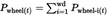
where:
=
total power at a driven wheel at time node (t) [kW]
=
number of driven wheels
Table 4
Data reporting format for measured data for the simulation tool in the verification test
| Quantity | Unit | Header input data | Comment |
|---|---|---|---|
| time node | [s] | <t> | |
| vehicle speed | [km/h] | <v> | |
| engine speed | [rpm] | <n_eng> | |
| engine cooling fan speed | [rpm] | <n_fan> | |
| torque left wheel | [Nm] | <tq_left> | |
| torque right wheel | [Nm] | <tq_right> | |
| wheel speed left | [rpm] | <n_wh_left> | |
| wheel speed right | [rpm] | <n_wh_right> | |
| gear | [-] | <gear> | optional signal for MT and AMT |
| fuel flow | [g/h] | <fc> | for standard NCV (point 7.2) |
7. Test evaluation U.K.
The simulated fuel consumption shall be compared to the measured fuel consumption using the simulation tool.
7.1. Simulation of the fuel consumption U.K.
The input data and input information for the simulation tool for the verification test shall be the following:
The certified CO 2 emissions and fuel consumption related properties of the following components, separate technical units or systems:
engines;
transmissions;
torque converters;
other torque transferring components;
additional driveline components;
axles.
The input data set out in Table 4.
The power calculated by the simulation tool by the equations of longitudinal dynamics from the measured vehicle speed and road gradient course may be used for plausibility checks to test if the total simulated cycle work is similar to the measured value.
The simulation tool shall calculate the gears engaged during the verification test by calculating the engine speeds per gear at the actual vehicle speed and selecting the gear that provides the engine speed closest to the measured engine speed.
The measured wheel power shall replace in the verification test mode of the simulation tool the simulated power demand at the wheels. The measured engine speed and the gear defined in the verification test input data shall replace the corresponding simulation part. The standard fan power in the simulation tool shall be replaced by the fan power calculated from the measured fan speed in the simulation tool as follows:
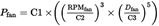
where:
=
fan power to be used in the simulation for the verification test [kW]
=
measured rotational speed of the fan [1/s]
=
diameter of the fan [m]
=
generic parameters in the simulation tool:
=
7 320 W
=
1 200 rpm
=
810 mm
The steering pump, compressor and generator shall be attributed standard values in accordance with Annex IX.
All other simulation steps and data handling concerning axle, transmission and engine efficiency shall be identical to the application of the simulation tool to determine and declare the CO 2 emissions and fuel consumption of new vehicles.
The simulated fuel consumption value shall be the total fuel flow over the verification test relevant test distance, from the end of the zeroing after the warm up phase to the end of the test. The total verification test relevant test distance shall be calculated from the vehicle speed signal.
The results from the simulation tool for the verification test shall be calculated as follows:

where:
=
Verification test work calculated by the simulation tool for the complete fuel consumption measurement phase [kWh]
=
Fuel consumption simulated by the simulation tool over the complete fuel consumption measurement phase [g/kWh]
=
Simulation rate [Hz]
=
Instantaneous fuel consumption simulated by the simulation tool over the test [g/s]
7.2. Calculation of the measured fuel consumption U.K.
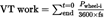
The measured fuel flow shall be integrated for the same time span as the simulated fuel consumption. The measured fuel consumption for the total test shall be calculated as follows:

where:
=
Fuel consumption measured by integrating fuel mass flow over the complete fuel consumption measurement phase [g/kWh]
=
Instantaneous fuel mass flow measured during the fuel consumption measurement phase [g/s]
=
Sampling rate [Hz]
=
Verification test work at the wheel calculated from the measured wheel torque and wheel rotational speeds over the complete fuel consumption measurement phase [kWh]

=
Positive power at the left (i = l) and right (i = 2) wheel calculated from the measured wheel torque and wheel rotational speeds at time step t where only power values greater zero are considered

=
instantaneously measured torque at the wheel ‘ i ’ in time step ‘ t ’ [Nm]
=
instantaneously measured rotational speed at the wheel ‘i’ in time step ‘t’ [min – 1 ]
The measured fuel consumption values shall be corrected for the net calorific value (NCV) as set out in point 3 of Annex V to calculate the verification test results.

where:
=
NCV of the fuel used in the verification test determined in accordance with point 3.2 of Annex V [MJ/kg]
=
Standard NCV in accordance with Table 4 of Annex V [MJ/kg]
=
Fuel consumption measured by integrating fuel mass over the complete fuel consumption measurement phase corrected for the test fuel NCV [g/kWh]
7.3. Pass/Fail check U.K.
The vehicle shall pass the verification test if the ratio of corrected measured fuel consumption to simulated fuel consumption is below the tolerances set out in Table 5.
In the case of a shorter run-in phase than 15 000 km the influence on the fuel efficiency of the vehicle may be corrected with the following evolution coefficient:

where:
=
Fuel consumption measured and corrected of a shorter run-in phase
=
run-in distance [km]
=
Evolution coefficient of 0,98
For vehicle odometer reading above 15 000 km, no correction shall be applied.
The ratio of measured and simulated fuel consumption for the total verification test relevant trip shall be calculated as verification test ratio in accordance with the following equation:

Where:
=
Ratio of fuel consumption measured and simulated in the verification testing procedure
For a comparison with the declared CO 2 emissions of the vehicle in accordance with Article 9, the verified CO 2 emissions of the vehicle are determined as follows:

where:
=
verified CO 2 emissions of the vehicle in [g/t-km]
=
declared CO 2 emissions of the vehicle in [g/t-km]
If a first vehicle fails the tolerances for C VTP , two more tests may be performed on the same vehicle or two more similar vehicles may be tested on request of the vehicle manufacturer. For the evaluation of the pass criterion set out in Table 5, the averages of the verification testing procedure ratio from the up to three tests shall be used. If the pass criterion is not reached, the vehicle fails the verification testing procedure.
Table 5
Pass fail criterion for the verification test
| C VPT | |
|---|---|
| Pass criterion for the verification testing procedure | < 1,075 |
8. Reporting procedures U.K.
The test report shall be established by the vehicle manufacturer for each vehicle tested and shall include at least the following results of the verification test: