- Y Diweddaraf sydd Ar Gael (Diwygiedig)
- Gwreiddiol (Fel y’i mabwysiadwyd gan yr UE)
Directive of the European Parliament and of the Council of 12 December 2006 laying down technical requirements for inland waterway vessels and repealing Council Directive 82/714/EEC (2006/87/EC) (repealed)
You are here:

Pa Fersiwn
Rhagor o Adnoddau
PDF o Fersiynau Diwygiedig
- ddiwygiedig 07/10/20180.44 MB
- ddiwygiedig 01/11/20136.93 MB
- ddiwygiedig 01/07/20138.56 MB
- ddiwygiedig 10/01/20138.55 MB
- ddiwygiedig 30/04/20093.23 MB
- ddiwygiedig 31/01/20092.55 MB
- ddiwygiedig 20/10/20082.15 MB
- ddiwygiedig 27/06/20083.80 MB
- ddiwygiedig 30/12/20061.76 MB
Deddfwriaeth yn deillio o’r UE
Pan adawodd y DU yr UE, cyhoeddodd legislation.gov.uk ddeddfwriaeth yr UE a gyhoeddwyd gan yr UE hyd at ddiwrnod cwblhau’r cyfnod gweithredu (31 Rhagfyr 2020 11.00 p.m.). Ar legislation.gov.uk, mae'r eitemau hyn o ddeddfwriaeth yn cael eu diweddaru'n gyson ag unrhyw ddiwygiadau a wnaed gan y DU ers hynny.


Mae'r eitem hon o ddeddfwriaeth yn tarddu o'r UE
Mae legislation.gov.uk yn cyhoeddi fersiwn y DU. Mae EUR-Lex yn cyhoeddi fersiwn yr UE. Mae Archif Gwe Ymadael â’r UE yn rhoi cipolwg ar fersiwn EUR-Lex o ddiwrnod cwblhau’r cyfnod gweithredu (31 Rhagfyr 2020 11.00 p.m.).
Status:
Dyma’r fersiwn wreiddiol (fel y’i gwnaed yn wreiddiol).
PART II
CHAPTER 3SHIPBUILDING REQUIREMENTS
Article 3.01Basic requirements
Vessels shall be built in accordance with good shipbuilding practice.
Article 3.02Strength and stability
1.The hull shall be sufficiently strong to withstand all of the stresses to which it is normally subjected.
(a)In the case of newly built vessels or major conversions affecting vessel strength, adequate strength shall be demonstrated by presenting design calculation proof. That proof is not required where a classification certificate or a declaration from an approved classification society is submitted.
(b)Where there is an inspection as referred to in Article 2.09 the minimum thicknesses of the bottom, bilge and side plates shall be checked in accordance with the following conditions:
For vessels made from steel minimum thickness tmin is given by the highest of the values resulting from the following formulae:
1.
for vessels that are longer than 40 m: tmin = f · b · c (2,3 + 0,04 L) (mm);
for vessels not more than 40 m in length: tmin = f · b · c (1,5 + 0,06 L) (mm), however, not less than 3.00 mm
2.

where:
a
=
frame spacing (mm);
f
=
frame spacing factor:
f
=
1 for a ≤ 500 mm
f
=
1 + 0,0013 (a — 500) for a > 500 mm
b
=
factor for bottom, side or bilge plates
b
=
1,0 for bottom plates and side plates
b
=
1,25 for bilge plates.
f = 1 may be taken for the frame spacing when calculating the minimum thickness of the side plates. However, the minimum thickness of the bilge plates may in no case be less than that of the bottom plates and side plates.
c
=
factor for the type of structure:
c
=
0,95 for vessels with double bottom and wing void, where the partition between wing void and hold is located vertically in line with the coaming
c
=
1,0 for all other types of structure.
(c)In longitudinally framed vessels with double bottom and wing voids, the minimum value calculated for the plate thickness in accordance with the formulae in paragraph (b) may be reduced to a calculated value certified by an approved classification society for sufficient hull strength (longitudinal, lateral and local strength).
Plates shall be renewed if bottom, bilge or side plates are below the permissible value laid down in this way.
The minimum values calculated in accordance with the method are limit values taking account of normal, uniform wear, and provided that shipbuilding steel is used and that the internal structural components such as frames, frame floor, main longitudinal and transverse structural members are in a good state and that the hull shows no indication of any overloading of the longitudinal strength.
As soon as these values are no longer achieved, the plates in question shall be repaired or replaced. However, lesser thicknesses, of not more than 10 % reduction from calculated values, are acceptable locally for small areas.
2.Where a material other than steel is used for the construction of the hull, it shall be proved by calculation that the hull strength (longitudinal, lateral and local strength) equals at least the strength that would result from the use of steel under the assumption of minimum thickness in accordance with paragraph1. If a certificate of class or a declaration issued by a recognised classification society is presented, a proof by calculation may be dispensed with.
3.The stability of vessels shall correspond to their intended use.
Article 3.03Hull
1.Bulkheads rising up to the deck or, where there is no deck, up to the gunwale, shall be installed at the following points:
(a)A collision bulkhead at a suitable distance from the bow in such a way that the buoyancy of the laden vessel is ensured, with a residual safety clearance of 100 mm if water enters the watertight compartment ahead of the collision bulkhead.
As a general rule, the requirement referred to in paragraph 1 shall be considered to have been met if the collision bulkhead has been installed at a distance of between 0,04 L and 0,04 L + 2 m measured from the forward perpendicular in the plane of maximum draught.
If this distance exceeds 0,04 L + 2 m, the requirement set out in paragraph 1 shall be proved by calculation.
The distance may be reduced to 0,03 L. In that case the requirement referred to in paragraph 1 shall be proved by calculation on the assumption that the compartment ahead of the collision bulkhead and those adjacent have all been filled with water.
(b)An aft-peak bulkhead at a suitable distance from the stern where the vessel length L exceeds 25 m.
2.No accommodation or installations needed for vessel safety or operation may be located ahead of the plane of the collision bulkhead. This requirement shall not apply to anchor gear.
3.The accommodation, engine rooms and boiler rooms, and the workspaces forming part of these shall be separated from the holds by watertight transverse bulkheads that extend up to the deck.
4.The accommodation shall be separated from engine rooms, boiler rooms and holds in a gastight manner and shall be directly accessible from the deck. If no such access has been provided an emergency exit shall also lead directly to the deck.
5.The bulkheads specified in paragraphs 1 and 3 and the separation of areas specified in paragraph 4 shall not contain any openings.
However, doors in the aft-peak bulkhead and penetrations, in particular for shafts and pipework, shall be permitted where they are so designed that the effectiveness of those bulkheads and of the separation of areas is not impaired. Doors in the aft-peak bulkhead shall be permitted only if it can be determined by remote monitoring in the wheelhouse whether they are open or closed and shall bear the following readily legible instruction on both sides:
‘Door to be closed immediately after use’.
6.The water inlets and discharges, and the pipework connected to these, shall be such that no unintentional ingress of water into the vessel is possible.
7.The foresections of vessels shall be built in such a way that the anchors neither wholly nor partly protrude beyond the side plating.
Article 3.04Engine and boiler rooms, bunkers
1.Engine or boiler rooms shall be arranged in such a way that the equipment therein can be operated, serviced and maintained easily and safely.
2.The liquid-fuel or lubricant bunkers and passenger areas and accommodation may not have any common surfaces which are under the static pressure of the liquid when in normal service.
3.Engine room, boiler room and bunker bulkheads, ceilings and doors shall be made of steel or another equivalent non-combustible material.
Insulation material used in engine rooms shall be protected against the intrusion of fuel and fuel vapours.
All openings in walls, ceilings, and doors of engine rooms, boiler rooms, and bunker rooms shall be such that they can be closed from outside the room. The locking devices shall be made from steel or an equivalently non-combustible material.
4.Engine and boiler rooms and other premises in which flammable or toxic gases are likely to escape shall be capable of being adequately ventilated.
5.Companionways and ladders providing access to engine and boiler rooms and bunkers shall be firmly attached and be made of steel or another shock-resistant and non-combustible material.
6.Engine and boiler rooms shall have two exits of which one may be an emergency exit.
The second exit may be dispensed with if:
(a)the total floor area (average length x average width at the level of the floor plating) of the engine or boiler room does not exceed 35 m2; and
(b)the path between each point where servicing or maintenance operations are to be carried out and the exit, or foot of the companionway near the exit providing access to the outside, is not longer than 5 m; and
(c)a fire extinguisher is located at the servicing point that is furthest removed from the exit door and also, by way of derogation from Article 10.03(1)(e), where the installed power of the engines does not exceed 100 kW.
7.The maximum permissible sound pressure level in the engine rooms shall be 110 dB(A). The measuring points shall be selected as a function of the maintenance work needed during normal operation of the plant located therein.
CHAPTER 4SAFETY CLEARANCE, FREEBOARD AND DRAUGHT MARKS
Article 4.01Safety clearance
1.The safety clearance shall be at least 300 mm.
2.The safety clearance in the case of vessels whose openings cannot be closed by spray-proof and weathertight devices, and for vessels sailing with their holds uncovered, shall be increased in such a way that each of those openings shall be at least 500 mm from the plane of maximum draught.
Article 4.02Freeboard
1.The freeboard of vessels with a continuous deck, without sheer and superstructures, shall be 150 mm.
2.The freeboard of vessels with sheer and superstructures shall be calculated using the following formula:

where:
a
is a correction coefficient that takes account of all of the superstructures involved;
βv
is a coefficient for correcting the effect of the forward sheer resulting from the presence of superstructures in the forward quarter of length L of the vessel;
βa
is a coefficient correcting the effect of the aft sheer resulting from the presence of superstructures in the aft quarter of length L of the vessel;
Sev
is the effective forward sheer in mm;
Sea
is the effective aft sheer in mm.
3.The coefficient α is calculated using the following formula:

where:
lem
is the effective length, in m, of a superstructure located in the median part corresponding to half of length L of the vessel;
lev
is the effective length, in m, of a superstructure in the forward quarter of vessel length L;
lea
is the effective length, in m, of a superstructure in the aft quarter of vessel length L.
The effective length of a superstructure is calculated using the following formulae:


where:
l
is the effective length, in m, of the superstructure involved;
b
is the width, in m, of the superstructure involved;
B1
is the width of the vessel, in m, measured on the outside of the vertical sideplates at deck level halfway along the superstructure involved;
h
is the height, in m, of the superstructure involved. However, in the case of hatches, h is obtained by reducing the height of the coamings by half of the safety distance according to Article 4.01(1) and (2). In no case will a value exceeding 0,36 m be taken for h.
If 

4.Coefficients βv and βa are calculated using the following formulae:


5.The effective aft/forward sheers Sev/Sea are calculated using the following formulae:
Sev = Sv · p
Sea = Sa · p
where:
Sv
is the actual forward sheer, in mm; however Sv shall not be taken to be more than 1 000 mm;
Sa
is the actual aft sheer, in mm; however Sa may not be taken to be more than 500 mm;

x
is the abscissa, measured from the extremity of the point where the sheer is 0,25 Sv or 0,25 Sa (see figure).

However, coefficient p will not be taken to be more than 1.
6.If βa · Sea is greater than βv · Sev, the value βv · Sev of will be taken as being the value for βa · Sea.
Article 4.03Minimum freeboard
In view of the reductions referred to in Article 4.02 the minimum freeboard shall be not less than 0 mm.
Article 4.04Draught marks
1.The plane of maximum draught shall be determined in such a way that the specifications concerning minimum freeboard and minimum safety clearance are both met. However, for safety reasons, the inspection body may lay down a greater value for the safety clearance or freeboard. The plane of maximum draught shall be determined at least for Zone 3.
2.The plane of maximum draught shall be indicated by means of highly visible, indelible draught marks.
3.The draught marks for Zone 3 shall consist of a rectangle 300 mm long and 40 mm deep, the base of which is horizontal and coincides with the plane of the maximum authorised draught. Any differing draught marks shall include such a rectangle.
4.Vessels shall have at least three pairs of draught marks, of which one pair shall be centrally located and the two others located, respectively, at a distance from the bow and stern that is equal to roughly one-sixth of the length.
However,
(a)where a vessel is less than 40 m in length it will suffice to affix two pairs of marks at a distance from the bow and stern, respectively, that is equal to a quarter of the length;
(b)where vessels are not intended for the carriage of goods, a pair of marks located roughly halfway along the vessel will suffice.
5.Marks or indications which cease to be valid following a further inspection shall be deleted or marked as being no longer valid under the supervision of the inspection body. If a draught mark should disappear, it may only be replaced under the supervision of an inspection body.
6.Where a vessel has been measured in implementation of the 1966 Convention on the Measurement of Inland Navigation Vessels and the plane of the measurement marks meets the requirements of this Directive, those measurement marks shall take the place of the draught marks; this shall be mentioned in the Community certificate.
7.For vessels operating on zones of inland waterways other than Zone 3 (Zones 1, 2 or 4) the bow and stern pairs of draught marks provided for in paragraph 4 shall be supplemented by adding a vertical line to which one or, in the case of several zones, several additional draught lines 150 mm long shall be affixed towards the bow, in relation to the draught mark for Zone 3.
This vertical line and the horizontal line shall be 30 mm thick. In addition to the draught mark towards the bow of the vessel, the relevant zone numbers shall be indicated in lettering 60 mm high × 40 mm deep (see Figure 1).

Article 4.05Maximum loaded draught of vessels whose holds are not always closed so as to be spray-proof and weathertight
If the plane of maximum draught for Zone 3 of a vessel is determined by assuming that the holds may be closed in such a way as to make them spray-proof and weathertight, and if the distance between the plane of maximum draught and the upper edge of the coamings is less than 500 mm, the maximum draught for sailing with uncovered holds shall be determined.
The following statement shall be entered on the Community certificate:
‘Where the hold hatches are totally or partly uncovered the vessel may only be loaded up to ... mm below the draught marks for Zone 3.’
Article 4.06Draught scales
1.Vessels whose draught may exceed 1 m shall bear a draught scale on each of their sides towards the stern; they may bear additional draught scales.
2.The zero points on each draught scale shall be taken vertically to this within the plane running parallel to the plane of maximum draught passing through the lowest point of the hull or of the keel where such exists. The vertical distance above the zero point shall be graduated in decimetres. That graduation shall be located on each scale, from the unladen water line up to 100 mm above the maximum draught by means of punched or chiselled marks, and shall be painted in the form of a highly-visible band in two alternating colours. That graduation shall be identified by figures at a distance of every five decimetres marked next to the scale as well as at the top of the scale.
3.The two stern measurement scales affixed pursuant to the Convention referred to in Article 4.04 (6), may replace the draught scales, provided that they include a graduation that meets the requirements plus, where appropriate, figures indicating the draught.
CHAPTER 5MANOEUVRABILITY
Article 5.01General
Vessels and convoys shall display adequate navigability and manoeuvrability.
Unpowered vessels intended to be towed shall meet the specific requirements laid down by the inspection body.
Powered vessels and convoys shall meet the requirements set out in Articles 5.02 to 5.10.
Article 5.02Navigation tests
1.Navigability and manoeuvrability shall be checked by means of navigation tests. Compliance with the requirements of Articles 5.06 to 5.10 shall, in particular, be examined.
2.The inspection body may dispense with all or part of the tests where compliance with the navigability and manoeuvrability requirements is proven in another manner.
Article 5.03Test area
1.The navigation tests referred to in Article 5.02 shall be carried out on areas of inland waterways that have been designated by the competent authorities.
2.Those test areas shall be situated on a stretch of flowing or standing water that is if possible straight, at least 2 km long and sufficiently wide and is equipped with highly-distinctive marks for determining the position of the vessel.
3.It shall be possible for the inspection body to plot the hydrological data such as depth of water, width of navigable channel and average speed of the current in the navigation area as a function of the various water levels.
Article 5.04Degree of loading of vessels and convoys during navigation tests
During navigation tests, vessels and convoys intended to carry goods shall be loaded to at least 70 % of their tonnage and loading, distributed in such a way as to ensure a horizontal attitude as far as possible. If the tests are carried out with a lesser load the approval for downstream navigation shall be restricted to that loading.
Article 5.05Use of on-board facilities for navigation test
1.During the navigation test, all of the equipment referred to in items 34 and 52 of the Community certificate which may be actuated from the wheelhouse may be used, apart from anchors.
2.However, during the test involving turning into the current referred to in Article 5.10, bow anchors may be used.
Article 5.06Prescribed (forward) speed
1.Vessels and convoys shall achieve a speed in relation to the water of at least 13 km/h. That condition is not mandatory where pusher tugs are operating solo.
2.The inspection body may grant exemptions to vessels and convoys operating solely in estuaries and ports.
3.The inspection body shall check if the unladen vessel is capable of exceeding a speed of 40 km/h in relation to water. If this can be confirmed, the following entry shall be made in item 52 of the Community certificate:
‘The vessel is capable of exceeding a speed of 40 km/h in relation to water.’
Article 5.07Stopping capacity
1.Vessels and convoys shall be able to stop facing downstream in good time while remaining adequately manoeuvrable.
2.Where vessels and convoys are not longer than 86 m and not wider than 22.90 m the stopping capacity mentioned above may be replaced by turning capacity.
3.The stopping capacity shall be proved by means of stopping manoeuvres carried out within a test area as referred to in Article 5.03 and the turning capacity by turning manoeuvres in accordance with Article 5.10.
Article 5.08Capacity for going astern
Where the stopping manoeuvre required by Article 5.07 is carried out in standing water it shall be followed by a navigation test while going astern.
Article 5.09Capacity for taking evasive action
Vessels and convoys shall be able to take evasive action in good time. That capacity shall be proven by means of evasive manoeuvres carried out within a test area as referred to in Article 5.03.
Article 5.10Turning capacity
Vessels and convoys not exceeding 86 m in length or 22,90 m in breadth shall be able to turn in good time.
That turning capacity may be replaced by the stopping capacity referred to in Article 5.07.
The turning capacity shall be proven by means of turning manoeuvres against the current.
CHAPTER 6STEERING SYSTEM
Article 6.01General requirements
1.Vessels shall be fitted with a reliable steering system which provides at least the manoeuvrability required by Chapter 5.
2.Powered steering systems shall be designed in such a way that the rudder cannot change position unintentionally.
3.The steering system as a whole shall be designed for permanent lists of up to 15° and ambient temperatures from — 20 oC to + 50 oC.
4.The component parts of the steering system shall be rugged enough to always be able to withstand the stresses to which they may be subjected during normal operation. No external forces applied to the rudder shall impair the operating capacity of the steering apparatus and its drive unit.
5.The steering system shall incorporate a powered drive unit if so required by the forces needed to actuate the rudder.
6.A steering apparatus with powered drive unit shall be protected against overloads by means of a system that restricts the torque applied by the drive unit.
7.The penetrations for the rudder stocks shall be so designed as to prevent the spread of water-polluting lubricants.
Article 6.02Steering apparatus drive unit
1.If the steering apparatus has a powered drive unit, it shall be possible to bring a second independent drive unit, or manual drive, into use within five seconds if the steering apparatus drive unit fails or malfunctions.
2.If the second drive unit or manual drive is not placed in service automatically, it shall be possible to do so immediately by means of a single operation by the helmsman that is both simple and quick.
3.The second drive unit or manual drive shall ensure the manoeuvrability required by Chapter 5 as well.
Article 6.03Hydraulic steering apparatus drive unit
1.No other power consumers may be connected to the hydraulic steering apparatus drive unit. Where there are two independent drive units, such a connection to one of the units is however acceptable if the consumers are connected to the return line and may be disconnected from the drive unit by means of an isolating device.
2.Where there are two hydraulic drive units, a separate hydraulic reservoir is needed for each of the two units. However, double reservoirs are acceptable. Hydraulic reservoirs shall be fitted with a warning system that monitors any drop in the oil level below the lowest content level needed for reliable operation.
3.The pilot valve does not have to be duplicated if this can be actuated manually or by manually-controlled hydraulic actuation from the wheelhouse.
4.The dimensions, design and arrangement of the pipework shall as far as possible exclude mechanical damage or damage resulting from fire.
5.As far as hydraulic drive units are concerned, no separate pipework system shall be required for the second unit if independent operation of the two units is guaranteed and if the pipework system is able to withstand a pressure of at least 1.5 times that of the maximum service pressure.
6.Flexible piping is only permitted where its use is essential in order to damp vibrations or to allow freedom of movement of components. It shall be designed for a pressure that is at least equal to the maximum service pressure.
Article 6.04Power source
1.Steering systems fitted with two powered drive units shall have at least two power sources.
2.If the second power source for the powered steering apparatus is not constantly available while the vessel is under way, a buffer device carrying adequate capacity shall provide back-up during the period needed for start-up.
3.In the case of electrical power sources, no other power consumers may be supplied by the main power source for the steering system.
Article 6.05Manual drive
1.The manual wheel shall not be driven by a powered drive unit.
2.Regardless of rudder position, a kick-back of the wheel shall be prevented when the manual drive is engaged automatically.
Article 6.06Rudder-propeller, water-jet, cycloidal-propeller and bow-thruster systems
1.Where the thrust vectoring of rudder-propeller, water-jet, cycloidal-propeller or bow-thruster installations is remotely actuated by electric, hydraulic or pneumatic means, there shall be two actuation systems, each independent of the other, between the wheelhouse and the propeller- or thruster-installation which, mutatis mutandis, meet the requirements of Articles 6.01 to 6.05.
Such systems are not subject to this paragraph if they are not needed in order to achieve the manoeuvrability required by Chapter 5 or if they are only needed for the stopping test.
2.Where there are two or more rudder-propeller, water-jet or cycloidal-propeller installations that are independent of each other the second actuation system is not necessary if the vessel retains the manoeuvrability required by Chapter 5 if one of the systems fails.
Article 6.07Indicators and monitoring devices
1.The rudder position shall be clearly displayed at the steering position. If the rudder-position indicator is electric it shall have its own power supply.
2.There shall be at least the following indicators and monitoring devices at the steering position:
(a)oil level in the hydraulic reservoirs in accordance with Article 6.03(2), and service pressure of the hydraulic system;
(b)failure of the electrical supply for the steering control;
(c)failure of the electrical supply for the drive units;
(d)failure of the rate-of-turn regulator;
(e)failure of the required buffer devices.
Article 6.08Rate-of-turn regulators
1.Rate-of-turn regulators and their components shall meet the requirements laid down in Article 9.20.
2.The proper functioning of the rate-of-turn regulator shall be displayed at the steering position by means of a green indicating light.
Any lack of or unacceptable variations in the supply voltage and an unacceptable decrease in the speed of rotation of the gyroscope shall be monitored.
3.Where, in addition to the rate-of-turn regulator, there are other steering systems, it shall be possible to clearly distinguish at the steering position which of these systems has been activated. It shall be possible to shift from one system to another immediately. The rate-of-turn regulator shall not have any influence on these other steering systems.
4.The electricity supply to the rate-of-turn regulator shall be independent of other power consumers.
5.The gyroscopes, detectors and rate-of-turn indicators used in the rate-of-turn regulators shall meet the minimum requirements of the minimum specifications and test conditions concerning rate-of-turn displays for inland waterways, as laid down in Annex IX.
Article 6.09Acceptance procedure
1.The compliance of the installed steering system shall be checked by an inspection body. It may, for this purpose, request the following documents:
(a)description of the steering system;
(b)drawings and information on the drive units and the steering controls;
(c)information concerning the steering apparatus;
(d)electrical wiring diagram;
(e)description of the rate-of-turn regulator;
(f)operating instructions for the steering system.
2.Operation of the entire steering system shall be checked by means of a navigation test. If a rate-of-turn regulator is installed it shall be checked that a predetermined course can be reliably maintained and that bends can be negotiated safely.
CHAPTER 7WHEELHOUSE
Article 7.01General
1.Wheelhouses shall be arranged in such a way that the helmsman may at all times perform his task while the vessel is under way.
2.Under normal operating conditions, sound pressure generated by the vessel and measured at the level of the helmsman's head at the steering position shall not exceed 70 dB(A).
3.Where a wheelhouse has been designed for radar navigation by one person, the helmsman shall be able to accomplish his task while seated and all of the display or monitoring instruments and all of the controls needed for operation of the vessel shall be arranged in such a way that the helmsman may use them comfortably while the vessel is under way without leaving his position or losing sight of the radar screen.
Article 7.02Unobstructed view
1.There shall be an adequately unobstructed view in all directions from the steering position.
2.The area of obstructed vision for the helmsman ahead of the vessel in an unladen state with half of its supplies but without ballast shall not exceed two vessel lengths or 250 m, whichever is less, to the surface of the water over an arc from abeam on either side through right ahead of the vessel.
Optical and electronic means for reducing the area of obstructed vision may not be taken into account during the inspection.
To further reduce any area of obstructed vision, only suitable electronic devices shall be used.
3.The helmsman's field of unobstructed vision at his normal position shall be at least 240° of the horizon and at least 140° within the forward semicircle.
No window frame, post or superstructure shall lie within the helmsman's usual axis of vision.
Even in the case where a field of unobstructed vision of at least 240° of the horizon is provided, the inspection body may require other measures and in particular the installation of suitable auxiliary optical or electronic devices if no sufficiently unobstructed view is provided towards the rear.
The height of the lower edge of the side windows shall be kept as low as possible and the height of the upper edge of the side and rear windows shall be kept as high as possible.
In determining whether the requirements in this Article for visibility from the wheelhouse are met, the helmsman shall be assumed to have a height of eye of 1 650 mm above the deck at the steering position.
4.The upper edge of the forward facing windows of the wheelhouse shall be high enough to allow a person at the steering position with height of eye of 1 800 mm a clear forward view to at least 10 degrees above the horizontal at eye-level height.
5.There shall in all weathers be suitable means of providing a clear view through the windscreen.
6.The glazing used in wheelhouses shall be made of safety glass and have a light transmission of at least 75 %.
To avoid reflections, the bridge front windows shall be glare-free and inclined from the vertical plane, so as to form an outward angle of not less than 10° and not more than 25°.
Article 7.03General requirements concerning control, indicating and monitoring equipment
1.Control equipment needed to operate the vessel shall be brought into its operating position easily. That position shall be unambiguously clear.
2.Monitoring instruments shall be easily legible. It shall be possible to adjust their lighting steplessly down to their extinction. Light sources shall be neither intrusive nor impair the legibility of the monitoring instruments.
3.There shall be a system for testing the warning and indicating lights.
4.It shall be possible to clearly establish whether a system is in operation. If its functioning is indicated by means of an indicating light, this shall be green.
5.Any malfunctioning or failure of systems that require monitoring shall be indicated by means of red warning lights.
6.An audible warning shall sound at the same time that a red warning light lights up. Audible warnings may be given by a single, collective signal. The sound pressure level of that signal shall exceed the maximum sound pressure level of the ambient noise at the steering position by at least 3 dB(A).
7.The audible warning shall be capable of being switched off after a malfunction or failure has been acknowledged. Such shutdown shall not prevent the alarm signal from being triggered by other malfunctions. The red warning lights shall only go out when the malfunction has been corrected.
8.The monitoring and indicating devices shall be automatically switched to an alternative power supply if their own power supply fails.
Article 7.04Specific requirements concerning control, indicating and monitoring equipment of main engines and steering system
1.It shall be possible to control and monitor the main engines and steering systems from the steering position. Main engines fitted with a clutch which can be actuated from the steering position, or driving a controllable pitch propeller which can be controlled from the steering position, need only to be capable of being started up and shut down from the engine room.
2.The control for each main engine shall take the form of a single lever which prescribes an arc within a vertical plane that is approximately parallel to the longitudinal axis of the vessel. Movement of that lever towards the bow of the vessel shall cause forward motion, whereas movement of the lever towards the stern shall cause the vessel to go astern. Clutch engagement and reversal of the direction of motion shall take place about the neutral position of that lever. The lever shall catch in the neutral position.
3.The direction of the propulsion thrust imparted to the vessel and the rotational speed of the propeller or main engines shall be displayed inside wheelhouses that have been designed for radar navigation by one person.
4.The indicating and monitoring devices required by Article 6.07(2), Article 8.03( 2), and Article 8.05 (13), shall be located at the steering position.
5.Vessels with wheelhouses designed for radar navigation by one person shall be steered by means of a lever. It shall be possible to move that lever easily by hand. The position of the lever in relation to the longitudinal axis of the vessel shall correspond precisely to the position of the rudder blades. It shall be possible to release hold of the lever in any given position without that of the rudder blades changing. The neutral position of the lever shall be clearly perceptible.
6.Where the vessel is fitted with bow rudders or special rudders, particularly for going astern, these shall be actuated in wheelhouses designed for radar navigation by one person by special levers which, mutatis mutandis, meet the requirements set out in paragraph 5.
That requirement shall also apply where, in convoys, the steering system fitted to craft other than those powering the convoy is used.
7.Where rate-of-turn regulators are used, it shall be possible for the rate-of-turn control to be released in any given position without altering the speed selected.
The control shall turn through a wide enough arc to guarantee adequately precise positioning. The neutral position shall be clearly perceptible from the other positions. The scale illumination shall be steplessly variable.
8.The remote-control equipment for the entire steering system shall be installed in a permanent manner and be arranged in such a way that the course selected is clearly visible. If the remote control equipment can be disengaged, it shall be equipped with an indicating device displaying the respective operational conditions ‘in service’ or ‘out of service’. The disposition and manipulation of the controls shall be functional.
For systems that are subsidiary to the steering system, such as active bow thrusters, remote-control equipment not permanently installed shall be acceptable provided that such a subsidiary installation can be activated by means of an override at any time within the wheelhouse.
9.In the case of rudder-propeller, water-jet, cycloidal-propeller and bow-thruster systems, equivalent devices shall be acceptable as control, indicating and monitoring devices.
The requirements set out in paragraphs 1 to 8 shall apply, mutatis mutandis, in view of the specific characteristics and arrangements selected for the abovementioned active steering and propulsion units. The position of the indicating device shall clearly show for each installation the direction of the thrust acting on the vessel or the direction of the jet .
Article 7.05Navigation lights, light signals and sound signals
1.In this Article the term:
(a)‘navigation lights’ means the masthead, side and stern lights, and the lights visible from all sides, the blue scintillating lights, yellow rapidly scintillating strong lights for high-speed vessels and blue lights for the carriage of dangerous goods;
(b)‘light signals’ means the lights accompanying the sound signals and assigned to the blue panel.
2.Current indicating lights or other equivalent devices, such as repeater lights, for monitoring the navigation lights shall be installed in the wheelhouse unless that monitoring can be performed direct from the wheelhouse.
3.In wheelhouses designed for radar navigation by one person, repeater lights shall be installed on the control panel in order to monitor the navigation lights and the light signals. Switches of navigation lights shall be included in the repeater lights or be adjacent to these and shall be clearly assigned to them.
The arrangement and colour of the repeater lights for the navigation lights and light signals shall correspond to the actual position and colour of those lights and signals.
The failure of a navigation light or light signal to function shall cause the corresponding repeater light either to go out or to provide a signal in another manner.
4.In wheelhouses designed for radar navigation by one person it shall be possible to activate the sound signals by a foot operated switch. That requirement shall not apply to the ‘do not approach’ signal in accordance with the applicable navigational authority regulations of the Member States.
5.Navigation lights shall meet the requirements set out in Annex IX, Part I.
Article 7.06Radar installations and rate-of-turn indicators
1.The radar equipment and rate-of-turn indicators shall be of a type that has been approved by the competent authority. The requirements concerning installation and operational testing of radar equipment and rate-of-turn indicators, as laid down in Annex IX, shall be met. Inland ECDIS equipment which can be operated in navigation mode shall be regarded as radar equipment. In addition the requirements of the Inland ECDIS standard shall be met.
The rate-of-turn indicator shall be located ahead of the helmsman and within his field of vision.
2.In wheelhouses designed for radar navigation by one person:
(a)the radar screen shall not be shifted significantly out of the helmsman's axis of view in its normal position;
(b)the radar image shall continue to be perfectly visible, without a mask or screen, whatever the lighting conditions outside the wheelhouse;
(c)the rate-of-turn indicator shall be installed directly above or below the radar image or be incorporated into this.
Article 7.07Radio telephony systems for vessels with wheelhouses designed for radar navigation by one person
1.Where vessel wheelhouses have been designed for radar navigation by one person, reception from the vessel-vessel networks and that of nautical information shall be via a loudspeaker, and outgoing communications via a fixed microphone. Send/receive shall be selected by means of a push-button.
It shall not be possible to use the microphones of those networks for the public correspondence network.
2.Where vessel wheelhouses designed for radar navigation by one person are equipped with a radio telephone system for the public correspondence network, reception shall be possible from the helmsman's seat.
Article 7.08Internal communication facilities on board
There shall be internal communication facilities on board vessels with a wheelhouse designed for radar navigation by one person.
It shall be possible to establish communication links from the steering position:
(a)
with the bow of the vessel or convoy;
(b)
with the stern of the vessel or convoy if no direct communication is possible from the steering position;
(c)
with the crew accommodation;
(d)
with the boatmaster's cabin.
Reception at all positions of these internal communication links shall be via loudspeaker, and transmission shall be via a fixed microphone. The link with the bow and stern of the vessel or convoy may be of the radio-telephone type.
Article 7.09Alarm system
1.There shall be an independent alarm system enabling the accommodation, engine rooms and, where appropriate, the separate pump rooms to be reached.
2.The helmsman shall have within reach an on/off switch controlling the alarm signal; switches which automatically return to the off position when released are not acceptable.
3.The sound pressure level for the alarm signal shall be at least 75 dB(A) within the accommodation area.
In engine rooms and pump rooms the alarm signal shall take the form of a flashing light that is visible on all sides and clearly perceptible at all points.
Article 7.10Heating and ventilation
Wheelhouses shall be equipped with an effective heating and ventilation system that can be regulated.
Article 7.11Stern-anchor operating equipment
On board vessels and convoys whose wheelhouse has been designed for radar navigation by one person and exceeding 86 m in length or 22,90 m in breadth it shall be possible for the helmsman to drop the stern anchors from his position.
Article 7.12Retractable wheelhouses
Retractable wheelhouses shall be fitted with an emergency lowering system.
All lowering operations shall automatically trigger a clearly audible acoustic warning signal. That requirement shall not apply if the risk of injury which may result from the lowering is prevented by appropriate design features.
It shall be possible to leave the wheelhouse safely whatever its position.
Article 7.13Entry in the Community certificate for vessels with wheelhouses designed for radar navigation by one person
Where a vessel complies with the special provisions for wheelhouses designed for radar navigation by one person as set out in Articles 7.01, 7.04 to 7.08 and 7.11, the following entry shall be made in the Community certificate:
‘The vessel has a wheelhouse designed for radar navigation by one person’.
CHAPTER 8ENGINE DESIGN
Article 8.01General
1.Engines and their ancillaries shall be designed, built and installed in accordance with best practice.
2.Installations requiring regular inspection, particularly steam boilers, other pressure vessels and their accessories, and lifts, shall meet the regulations applying in one of the Member States of the Community.
3.Only internal-combustion engines burning fuels having a flashpoint of more than 55 oC may be installed.
Article 8.02Safety equipment
1.Engines shall be installed and fitted in such a way as to be adequately accessible for operation and maintenance and shall not endanger the persons assigned to those tasks. It shall be possible to make them secure against unintentional starting.
2.Main engines, auxiliaries, boilers and pressure vessels, and their accessories, shall be fitted with safety devices.
3.In case of emergency, it shall also be possible to shut down the motors driving the blower and suction fans from outside the space in which they are located, and from outside the engine room.
4.Where necessary, connections of pipes which carry fuel oil, lubricating oil, and oils used in power transmission systems, control and activating systems and heating systems shall be screened or otherwise suitably protected to avoid oil spray or leakages onto hot surfaces, into machinery air intakes, or other sources of ignition. The number of connections in such piping systems shall be kept to a minimum.
5.External high pressure fuel delivery pipes of diesel engines, between the high pressure fuel pumps and fuel injectors, shall be protected with a jacketed piping system capable of containing fuel from a high pressure pipe failure. The jacketed piping system shall include a means for collection of leakages and arrangements shall be provided for an alarm to be given of a fuel pipe failure, except that an alarm is not required for engines with no more than two cylinders. Jacketed piping systems need not be applied to engines on open decks operating windlasses and capstans.
6.Insulation of engine parts shall meet the requirements of Article 3.04(3), second paragraph.
Article 8.03Power plant
1.It shall be possible to start, stop or reverse the ship's propulsion reliably and quickly.
2.The following shall be monitored by suitable devices which trigger an alarm once a critical level has been reached:
(a)the temperature of the main-engine cooling water;
(b)the lubricating-oil pressure for the main engines and transmissions;
(c)the oil and air pressure of the main engine reversing units, reversible transmissions or propellers.
3.Where vessels have only one main engine, that engine shall not be shut down automatically except in order to protect against overspeed.
4.Where vessels have only one main engine, that engine may be equipped with an automatic device for the reduction of the engine speed only if an automatic reduction of the engine speed is indicated both optically and acoustically in the wheelhouse and the device for the reduction of the engine speed can be switched off from the helmsman's position.
5.Shaft bushings shall be designed in such a way as to prevent the spread of water-polluting lubricants.
Article 8.04Engine exhaust system
1.The exhaust gases shall be completely ducted out of the vessel.
2.All suitable measures shall be taken to avoid ingress of the exhaust gases into the various compartments. Exhaust pipes passing through accommodation or the wheelhouse shall, within these, be covered by protective gas-tight sheathing. The gap between the exhaust pipe and this sheathing shall be open to the outside air.
3.The exhaust pipes shall be arranged and protected in such a way that they cannot cause a fire.
4.The exhaust pipes shall be suitably insulated or cooled in the engine rooms. Protection against physical contact may suffice outside the engine rooms.
Article 8.05Fuel tanks, pipes and accessories
1.Liquid fuels shall be stored in steel tanks which are either an integral part of the hull or which are firmly attached to the hull. If so required by the design of the vessel, an equivalent material in terms of fire-resistance may be used. These requirements shall not apply to tanks having a capacity of no more than 12 litres that have been incorporated in auxiliaries during their manufacture. Fuel tanks shall not have common partitions with drinking-water tanks.
2.Tanks and their pipework and other accessories shall be laid out and arranged in such a way that neither fuel nor fuel vapours may accidentally reach the inside of the vessel. Tank valves intended for fuel sampling or water drainage shall close automatically.
3.No fuel tanks may be located forward of the collision bulkhead.
4.Fuel tanks and their fittings shall not be located directly above engines or exhaust pipes.
5.The filler orifices for fuel tanks shall be marked distinctly.
6.The orifice for the fuel tank filler necks shall be on the deck, except for the daily-supply tanks. The filler neck shall be fitted with a connection piece in accordance with European standard EN 12827:1999.
Such tanks shall be fitted with a breather pipe terminating in the open air above the deck and arranged in such a way that no water ingress is possible. The cross-section of the breather pipe shall be at least 1,25 times the cross-section of the filler neck.
If tanks are interconnected, the cross-section of the connecting pipe shall be at least 1,25 times the cross-section of the filler neck.
7.Directly at tank outlets the pipework for the distribution of fuels shall be fitted with a shutoff device that can be operated from the deck
This requirement shall not apply to tanks mounted directly on the engine.
8.Fuel pipes, their connections, seals and fittings shall be made of materials that are able to withstand the mechanical, chemical and thermal stresses to which they are likely to be subjected. The fuel pipes shall not be subjected to any adverse influence of heat and it shall be possible to inspect them throughout their length.
9.Fuel tanks shall be provided with a suitable capacity-gauging device. Capacity-gauging devices shall be legible right up to the maximum filling level. Glass gauges shall be effectively protected against impacts, shall be fitted with an automatic closing device at their base and their upper end shall be connected to the tanks above their maximum filling level. The material used for glass gauges shall not deform under normal ambient temperatures. Sounding pipes shall not terminate in accommodation spaces. Sounding pipes terminating in an engine or boiler room shall be fitted with suitable self-closing devices.
10.(a)Fuel tanks shall be safeguarded against fuel spills during bunkering by means of appropriate onboard technical devices which shall be entered in item 52 of the Community certificate.
(b)If fuel is taken on from bunkering stations with their own technical devices to prevent fuel spills on board during bunkering, the equipment requirements in (a) and paragraph 11 shall no longer apply.
11.If fuel tanks are fitted with an automatic shut-off device, the sensors shall stop fuelling when the tank is 97 % full; this equipment shall meet the ‘failsafe’ requirements.
If the sensor activates an electrical contact, which can break the circuit provided by the bunkering station by a binary signal, it shall be possible to transmit the signal to the bunkering station by means of a watertight connection plug meeting the requirements of IEC publication 60309-1:1999 for 40 to 50 V DC, housing colour white, earthing contact position ten o'clock.
12.Fuel tanks shall be provided with openings having leak-proof closures that are intended to permit cleaning and inspection.
13.Fuel tanks directly supplying the main engines and engines needed for safe operation of the vessel shall be fitted with a device emitting both visual and audible signals in the wheelhouse if their level of filling is not sufficient to ensure further safe operation.
Article 8.06Storage of lubricating oil, pipes and accessories
1.Lubricating oil shall be stored in steel tanks which are either an integral part of the hull or which are firmly attached to the hull. If so required by the design of the vessel, an equivalent material in terms of fire-resistance may be used. These requirements shall not apply to tanks having a capacity of no more than 25 litres. Lubricating oil tanks shall not have common partitions with drinking-water tanks.
2.Lubricating oil tanks and their pipework and other accessories shall be laid out and arranged in such a way that neither lubricating oil nor lubricating oil vapour may accidentally reach the inside of the vessel.
3.No lubricating oil tanks may be located forward of the collision bulkhead.
4.Lubricating oil tanks and their fittings shall not be located directly above engines or exhaust pipes.
5.The filler orifices for lubricating oil tanks shall be marked distinctly.
6.Lubricating oil pipes, their connections, seals and fittings shall be made of materials that are able to withstand the mechanical, chemical and thermal stresses to which they are likely to be subjected. The pipes shall not be subjected to any adverse influence of heat and it shall be possible to inspect them throughout their length.
7.Lubricating oil tanks shall be provided with a suitable capacity-gauging device. Capacity-gauging devices shall be legible right up to the maximum filling level. Glass gauges shall be effectively protected against impacts, shall be fitted with an automatic closing device at their base and their upper end shall be connected to the tanks above their maximum filling level. The material used for glass gauges shall not deform under normal ambient temperatures. Sounding pipes shall not terminate in accommodation spaces. Sounding pipes terminating in an engine or boiler room shall be fitted with suitable self-closing devices.
Article 8.07Storage of oils used in power transmission systems, control and activating systems and heating systems, pipes and accessories
1.Oils used in power transmission systems, control and activating systems and heating systems shall be stored in steel tanks which are either an integral part of the hull or which are firmly attached to the hull. If so required by the design of the vessel, an equivalent material in terms of fire-resistance may be used. These requirements shall not apply to tanks having a capacity of no more than 25 litres. Such oil tanks shall not have common partitions with drinking-water tanks.
2.Such oil tanks and their pipework and other accessories shall be laid out and arranged in such a way that neither such oil nor such oil vapour may accidentally reach the inside of the vessel.
3.No such oil tanks may be located forward of the collision bulkhead.
4.Such oil tanks and their fittings shall not be located directly above engines or exhaust pipes.
5.The filler orifices for such oil tanks shall be marked distinctly.
6.Such oil pipes, their connections, seals and fittings shall be made of materials that are able to withstand the mechanical, chemical and thermal stresses to which they are likely to be subjected. The pipes shall not be subjected to any adverse influence of heat and it shall be possible to inspect them throughout their length.
7.Such oil tanks shall be provided with a suitable capacity-gauging device. Capacity-gauging devices shall be legible right up to the maximum filling level. Glass gauges shall be effectively protected against impacts, shall be fitted with an automatic closing device at their base and their upper end shall be connected to the tanks above their maximum filling level. The material used for glass gauges shall not deform under normal ambient temperatures. Sounding pipes shall not terminate in accommodation spaces. Sounding pipes terminating in an engine or boiler room shall be fitted with suitable self-closing devices.
Article 8.08Bilge pumping and drainage systems
1.It shall be possible to pump out each watertight compartment separately. However, that requirement shall not apply to watertight compartments that are normally sealed hermetically during operation.
2.Vessels requiring a crew shall be equipped with two independent bilge pumps which shall not be installed within the same space. At least one of these shall be motor driven. However, for vessels with a power of less than 225 kW or with a deadweight of less than 350 t, or where vessels not intended for the carriage of goods have a displacement of less than 250 m3, one pump will suffice which can be either manually-operated or motor-driven.
Each of the required pumps shall be capable of use on each watertight compartment.
3.The minimum pumping capacity Q1 of the first bilge pump shall be calculated using the following formula:
Q1 = 0,1 · d1 2 (1/min)
d1 is calculated via the formula:

The minimum pumping capacity Q2 of the second bilge pump shall be calculated using the following formula:
Q2 = 0,1 · d2 2 (l/min)
d2 is calculated using the formula:

However, the value d2 need not exceed value d1.
For the calculation of Q2 l shall be taken to be the length of the longest watertight compartment.
In these formulae:
l
is the length of the watertight compartment in question, in (m);
d1
is the calculated internal diameter of the main drainage pipe, in (mm);
d2
is the calculated internal diameter of the branch pipe, in (mm).
4.Where the bilge pumps are connected to a drainage system the drainage pipes shall have an internal diameter of at least d1, in mm, and the branch pipes an internal diameter of at least d2, in mm.
Where vessels are less than 25 m in length the values d1 and d2 may be reduced to 35 mm.
5.Only self-priming bilge pumps are permitted.
6.There shall be at least one suction on both the starboard and port sides of all flat-bottomed, drainable compartments that are wider than 5 m.
7.It may be possible to drain the aft peak via the main engine room by means of an easily accessible, automatically closable fitting.
8.Branch pipes of single compartments shall be connected to the main drainage pipe by means of a lockable non-return valve.
Compartments or other spaces that are capable of carrying ballast need to be connected to the drainage system only by means of a simple closing device. That requirement shall not apply to holds that are capable of carrying ballast. Such holds shall be filled with ballast water by means of ballast piping that is permanently installed and independent of the drainage pipes, or by means of branch pipes that can be connected to the main drainage pipe by flexible pipes or flexible adaptors. Water intake valves located in the bottom of the hold shall not be permitted for this purpose.
9.Hold bilges shall be fitted with gauging devices.
10.Where a drainage system incorporates permanently installed pipework the bilge-bottom drainage pipes intended to extract oily water shall be equipped with closures that have been sealed in position by an inspection body. The number and position of those closures shall be entered on the Community certificate.
11.Locking the closures in position shall be regarded as equivalent to sealing in accordance with paragraph 10. The key or keys for the locking of the closures shall be indicated accordingly and kept in a marked and easily accessible location in the engine room.
Article 8.09Oily water and used oil stores
1.It shall be possible to store, on board, oily water accumulated during operation. The engine-room bilge is considered to be a store for this purpose.
2.In order to store used oils there shall, in the engine room, be one or several specific receptacles whose capacity corresponds to at least 1,5 times the quantity of the used oils from the sumps of all of the internal combustion engines and transmissions installed, together with the hydraulic fluids from the hydraulic-fluid tanks.
The connections used in order to empty the receptacles referred to above shall comply with European standard EN 1305:1996.
3.Where vessels are only used on short-haul operation the inspection body may grant exceptions from the requirements ofparagraph 2.
Article 8.10Noise emitted by vessels
1.The noise produced by a vessel under way, and in particular the engine air intake and exhaust noises, shall be damped by using appropriate means.
2.The noise generated by a vessel under way shall not exceed 75 dB(A) at a lateral distance of 25 m from the ship's side.
3.Apart from transhipment operations the noise generated by a stationary vessel shall not exceed 65 dB(A) at a lateral distance of 25 m from the ship's side.
CHAPTER 8a(Left void)
CHAPTER 9ELECTRICAL EQUIPMENT
Article 9.01General
1.Where there are no specific requirements concerning certain parts of an installation the safety level shall be considered satisfactory where those parts have been produced in accordance with a European standard in force or in accordance with the requirements of an approved classification society.
The relevant documents shall be submitted to the inspection body.
2.Documents containing the following, and duly stamped by the inspection body, shall be kept on board:
(a)general drawings concerning the entire electrical installation;
(b)switching diagrams for the main switchboard, the emergency switchboard and the distribution switchboard, together with the most important technical data such as the amperage and rated current of the protection and control devices;
(c)power data concerning the electrical machinery and equipment;
(d)types of cable and information on conductor cross-sections.
It is not necessary to keep such documents on board unmanned craft, but they shall be available at all times with the owner.
3.The equipment shall be designed for permanent lists of up to 15° and ambient inside temperatures of between 0 and + 40 °C, and on the deck between - 20 °C and + 40 °C. It shall function perfectly within those limits.
4.The electrical and electronic equipment and appliances shall be fully accessible and easy to maintain.
Article 9.02Electricity supply systems
1.Where craft are fitted with an electrical system, that system shall in principle have at least two power sources in such a way that where one power source fails the remaining source is able to supply the power consumers needed for safe navigation for at least 30 minutes.
2.Adequate rating of the power supply shall be demonstrated by means of a power balance. An appropriate simultaneity factor may be taken into account.
3.Independently of paragraph 1, Article 6.04 shall apply to the power source for the steering system (rudder installations).
Article 9.03Protection against physical contact, intrusion of solid objects and the ingress of water
The type of minimum protection for permanently installed parts of an installation shall be as set out in the following table:
| a Where appliances release large amounts of heat: IP 12. | ||||||
| b Where appliances or panels do not have this type of protection their location shall meet the conditions applying to that type of protection. | ||||||
| c Electrical equipment of the certified safety type as in accordance with (a) European standards EN 50014: 1997; 50015: 1998; 50016: 2002; 50017: 1998; 50018: 2000; 50019: 2000 and 50020: 2002; or (b) IEC publication 60079 as of 1 October 2003. | ||||||
| Location | Type of minimum protection(in accordance with IEC publ. 60529: 1992) | |||||
|---|---|---|---|---|---|---|
| Generators | Motors | Trans-formers | PanelsDistributorsSwitches | Fittings | Lighting equipment | |
| Operation rooms, engine rooms, steering-gear compartments | IP 22 | IP 22 | IPb 22 | IPa b 22 | IP 44 | IP 22 |
| Holds | IP 55 | IP 55 | ||||
| Battery and paint lockers | IP 44 u. (Ex)c | |||||
| Free decks and open steering positions | IP 55 | IP 55 | IP 55 | IP 55 | ||
| Wheelhouse | IP 22 | IP 22 | IP 22 | IP 22 | IP 22 | |
| Accommodation apart from sanitary facilities and washrooms | IP 22 | IP 20 | IP 20 | |||
| Sanitary facilities and washrooms | IP 44 | IP 44 | IP 44 | IP 55 | IP 44 | |
Article 9.04Protection from explosion
Only explosion-proof electrical equipment (certified safety) may be installed in spaces where potentially explosive gases or mixtures of gases are likely to accumulate, such as compartments dedicated for accumulators or the storage of highly inflammable products. No light switches or switches for other electrical appliances shall be installed in these spaces. The protection from explosion shall take account of the characteristics of the potentially explosive gases or mixtures of gases that are likely to arise (explosion-potential group, temperature class).
Article 9.05Earthing
1.Systems under a voltage of more than 50 V need to be earthed.
2.Metal parts that are open to physical contact and which, during normal operation, are not electrically live, such as engine frames and casings, appliances and lighting equipment, shall be earthed separately where they are not in electrical contact with the hull as a result of their installation.
3.The casings of mobile power consumers and portable devices shall, during normal use, be earthed by means of an additional earthing conductor that is incorporated into the power cable.
That provision shall not apply where a protective circuit-separation transformer is used, nor to appliances fitted with protective insulation (double insulation).
4.The cross-sections of the earthing conductors shall be not less than given in the following table:
| Cross-section of outside conductors(mm2) | Minimum cross-section of earthing conductors | |
|---|---|---|
| within insulated cables(mm2) | fitted separately(mm2) | |
| from 0,5 to 4 | same cross-section as that of the outside conductor | 4 |
| more than 4 to 16 | same cross-section as that of the outside conductor | same cross-section as that of the outside conductor |
| more than 16 to 35 | 16 | 16 |
| more than 35 to 120 | half of the cross-section of the outside conductor | half of the cross-section of the outside conductor |
| more than 120 | 70 | 70 |
Article 9.06Maximum permissible voltages
1.The following voltages shall not be exceeded:
| a Where that voltage comes from higher-voltage networks galvanic separation shall be used (safety transformer). | |||
| b All of the poles of the secondary circuit shall be insulated from the earth. | |||
| Type of installation | Maximum permissible voltage | ||
|---|---|---|---|
| Direct current | Single-phase alternating current | Three-phase alternating current | |
a. Power and heating installations including the sockets for general use | 250 V | 250 V | 500 V |
b. Lighting, communications, command and information installations including the sockets for general use | 250 V | 250 V | - |
c. Sockets intended to supply portable devices used on open decks or within narrow or damp metal lockers, apart from boilers and tanks: | |||
1. In general | 50 Va | 50 Va | - |
2. Where a protective circuit-separation transformer only supplies one appliance | - | 250 Vb | - |
3. Where protective-insulation (double insulation) appliances are used | 250 V | 250 V | - |
4. Where ≤ 30 mA default current circuit breakers are used. | - | 250 V | 500 V |
d. Mobile power consumers such as electrical equipment for containers, motors, blowers and mobile pumps which are not normally moved during service and whose conducting parts which are open to physical contact are earthed by means of an earthing conductor that is incorporated into the connecting cable and which, in addition to that earthing conductor, are connected to the hull by their specific positioning or by an additional conductor | 250 V | 250 V | 500 V |
e. Sockets intended to supply portable appliances used inside boilers and tanks | 50 Va | 50 Va | - |
2.By way of derogation from paragraph1, if the necessary protective measures are applied higher voltages shall be acceptable:
(a)for power installations where their power so requires;
(b)for special on-board installations such as radio and ignition systems.
Article 9.07Distribution systems
1.The following distribution systems are allowed for direct current and single-phase alternating current:
(a)two-conductor systems of which one is earthed (L1/N/PE);
(b)single-conductor systems using the hull return principle, only for local installations (for example, starting gear for combustion engines, cathodic protection) (L1/PEN);
(c)two-conductor systems that are insulated from the hull (L1/L2/PE).
2.The following distribution systems are allowed for three-phase alternating current:
(a)four-conductor systems with earthing of the neutral point, not using the hull return principle (L1/L2/L3/N/PE) = (network TN-S) or (network TT);
(b)three-conductor systems insulated from the hull (Ll/L2/L3/PE) = (network IT);
(c)three-conductor systems with earthing of the neutral point using the hull return principle, however, that shall not be allowed for terminal circuits (L1/L2/L3/PEN).
3.The inspection body may allow the use of other systems.
Article 9.08Connection to shore or other external networks
1.Incoming supply lines from shore networks or other external networks to the installations of the onboard network shall have a permanent connection on board in the form of fixed terminals or fixed plug sockets. The cable connections shall not be subjected to any pulling load.
2.The hull shall be capable of being earthed effectively when the connection voltage exceeds 50 V. The earthing connection shall be specially marked.
3.The switching devices for the connection shall be arranged such as to prevent the concurrent operation of the onboard network generators and the shore network or another external network. A brief period of concurrent operation shall be permitted when changing from one system to another without a break in voltage.
4.The connection shall be protected against short circuiting and overload.
5.The main switchboard shall indicate whether the connection is live.
6.Indicator devices shall be installed to enable comparison of polarity in the case of direct current and phase sequence in the case of three-phase alternating current, between the connection and the onboard network.
7.A panel adjacent to the connection shall indicate:
(a)the measures required to establish the connection;
(b)the type of current and the nominal voltage and, for alternating current, the frequency.
Article 9.09Power supply to other craft
1.When power is supplied to other craft, a separate connection shall be used. If power sockets rated at more than 16 A are used to supply current to other craft, devices (such as switches or interlocks) shall be provided to ensure that connection and disconnection can take place only when the line is dead.
2.Cable connections shall not be subjected to any pulling load.
3.Article 9.08, paragraphs 3 to 7, shall apply mutatis mutandis.
Article 9.10Generators and motors
1.Generators, motors and their terminal boxes shall be accessible for inspections, measurements and repairs. The type of protection shall correspond to their location (see Article 9.03).
2.Generators driven by the main engine, the propeller shaft or by an auxiliary set intended for other purposes shall be designed with respect to the range of rotational speeds which can occur during normal operation.
Article 9.11Accumulators
1.Accumulators shall be accessible and so arranged as not to shift due to movements of the craft. They shall not be placed where they will be exposed to excessive heat, extreme cold, spray, steam or vapour.
They shall not be installed in the wheelhouse, accommodation or holds. This requirement shall not apply to accumulators for portable appliances, or to accumulators requiring a charging power of less than 0,2 kW.
2.Accumulators requiring a charging power of more than 2,0 kW (calculated on the basis of the maximum charging current and the nominal voltage of the accumulator and taking into account the characteristic charging curve of the charging appliance) shall be installed in a special room. If placed on deck enclosing them in a cabinet will suffice.
Accumulators requiring a charging power not exceeding 2,0 kW may be installed in a cabinet or chest not only if placed on deck but also below decks. They may also be installed in an engine room or any other well-ventilated space provided that they are protected against falling objects and dripping water.
3.The interior surfaces of all rooms, cabinets or boxes, shelving or other built-in features intended for accumulators shall be protected against the harmful effects of electrolytes.
4.Provision shall be made for effective ventilation when accumulators are installed in a closed compartment, cabinet or chest. Forced-draught ventilation shall be provided for nickel-cadmium accumulators requiring a charging power of more than 2 kW and for lead-acid accumulators requiring more than 3 kW.
The air shall enter at the bottom and be discharged at the top so as to ensure total gas extraction.
Ventilation ducts shall not include any devices which obstruct the air flow, such as stop valves.
5.The required air throughput (Q) shall be calculated using the following formula:
Q = 0,11 · I · n (m3/h)
where:

n
=
the number of cells.
In the case of buffer accumulators within the onboard network other methods of calculation taking into account the characteristic charging curve of the charging device may be accepted by the inspection body, provided that these methods are based on the provisions of approved classification societies or on relevant standards.
6.Where natural ventilation is used the cross-section of the ducts shall be sufficient for the required air throughput on the basis of an air-flow velocity of 0,5 m/section. However, the cross-section shall be at least 80 cm2 for lead-acid accumulators and 120 cm2 for nickel-cadmium accumulators.
7.Where forced-draught ventilation is used a fan shall be provided, preferably of the suction type, whose motor shall be clear of the gas or air stream.
Fans shall be so designed as to preclude the generation of sparks through contact between a blade and the fan casing and to avoid any electrostatic charges.
8.‘Fire, naked flame and smoking prohibited’ signs according to Figure 2 of Appendix I having a minimum diameter of 10 cm shall be affixed to the doors or covers of compartments, cabinets and chests containing accumulators.
Article 9.12Switchgear installations
1.Electrical switchboards
(a)Appliances, switches, fuses and switchboard instruments shall be clearly arranged and shall be accessible for maintenance and repair.
Terminals for voltages up to 50 V, and those for voltages higher than 50 V, shall be kept separate and marked appropriately.
(b)For all switches and appliances marker plates identifying the circuit shall be affixed to the switchboards.
The nominal amperage and the circuit for fuses shall be identified.
(c)When appliances with an operating voltage greater than 50 V are installed behind doors the live components of those appliances shall be protected against accidental contact while the doors are open.
(d)The materials of switchboards shall have suitable mechanical strength and be durable, flame-retardant and self-extinguishing; they shall not be hygroscopic.
(e)If high rupture capacity (HRC)-fuses are installed in electrical switchboards, accessories and personal protective equipment shall be available for installing and removing such fuses.
2.Switches, protective devices
(a)Generator circuits and power consumer circuits shall be protected against short circuiting and overload on all non-earthed conductors. Switching devices triggered by short-circuiting and overload or fuses may be used for this purpose.
Circuits supplying electric motors of drive units (steering system) and their control circuits shall only be protected against short circuiting. Where circuits include thermal circuit-breakers these shall be neutralised or set at not less than twice the nominal amperage.
(b)Outputs from the main switchboard to power consumers operating at more than 16 A shall include a load or power switch.
(c)Power consumers for the propulsion of the craft, the steering system, the rudder position indicator, navigation or safety systems, and power consumers with a nominal amperage greater than 16 A shall be supplied by separate circuits.
(d)The circuits of power consumers required for propelling and manoeuvring the vessel shall be supplied directly by the main switchboard.
(e)Circuit-breaking equipment shall be selected on the basis of nominal amperage, thermal or dynamic strength, and breaking capacity. Switches shall simultaneously cut off all live conductors. The switching position shall be identifiable.
(f)Fuses shall be of the enclosed-melt type and be made of ceramic or an equivalent material. It shall be possible to change them without any danger of physical contact for the operator.
3.Measuring and monitoring devices
(a)Generator, accumulator and distribution circuits shall be equipped with measuring and monitoring devices where the safe operation of the installation so requires.
(b)Non-earthed networks with a voltage of more than 50 V shall be equipped with an earthing detection device capable of giving both visual and audible alarm. In secondary installations such as control circuits, this device may be dispensed with.
4.Location of electrical switchboards
(a)Switchboards shall be located in accessible and well-ventilated spaces and be protected against water and mechanical damage.
Piping and air ducts shall be so arranged that in the event of leakage the switchboards cannot be damaged. If their installation near electrical switchboards is inevitable, pipes shall not have detachable connections nearby.
(b)Cabinets and wall recesses in which unprotected switching devices are installed shall be of a flame-retardant material or be protected by a metal or other flame-retardant sheathing.
(c)When the voltage is greater than 50 V, insulating gratings or mats shall be placed at the operator's position in front of the main switchboard.
Article 9.13Emergency circuit breakers
Emergency circuit breakers for oil burners, fuel pumps, fuel separators and engine-room ventilators shall be installed centrally outside the spaces containing the equipment.
Article 9.14Installation fittings
1.Cable entries shall be sized as a function of the cables to be connected and be appropriate to the types of cable used.
2.Sockets for distribution circuits at different voltages or frequencies shall be impossible to confuse.
3.Switches shall simultaneously switch all non-earthed conductors within a circuit. However, single-pole switches within non-earthed circuitry shall be permitted in accommodation-lighting circuits apart from in laundries, bathrooms, washrooms and other rooms with wet facilities.
4.Where amperage exceeds 16 A it shall be possible to lock the sockets by means of a switch in such a way that the plug can only be inserted and withdrawn with the power switched off.
Article 9.15Cables
1.Cables shall be flame-retardant, self-extinguishing and resistant to water and oil.
In accommodation, other types of cable may be used, provided that they are effectively protected, have flame-retardant characteristics and are self-extinguishing.
Flame-retardant standards of electric cables shall be in accordance with:
(a)IEC publications 60332-1:1993, 60332-3:2000; or
(b)equivalent regulations recognised by one of the Member States.
2.Conductors of cables used for power and lighting circuits shall have a minimum cross-section of 1,5 mm2.
3.Metal armouring, shielding and sheathing of cables shall not, under normal operating conditions, be used as conductors or for earthing.
4.Metal shielding and sheathing of cables in power and lighting installations shall be earthed at least at one end.
5.The cross-section of conductors shall take account of their maximum permissible end-temperature (current-carrying capacity) and of the permissible voltage drop. The voltage drop between the main switchboard and the least favourable point of the installation shall not be more than 5 % for lighting or more than 7 % for power or heating circuits, referred to the nominal voltage.
6.Cables shall be protected against mechanical damage.
7.The means of fixing the cables shall ensure that any pulling load remains within the permissible limits.
8.When cables pass through bulkheads or decks, the mechanical strength, watertightness and fire resistance of these bulkheads and decks shall not be affected by the penetrations.
9.Terminations and joints in all conductors shall be so made as to retain the original electrical, mechanical, flame-retardant and, where necessary, fire resistant properties.
10.Cables connected to retractable wheelhouses shall be sufficiently flexible and shall have insulation with sufficient flexibility down to — 20 °C and resistance to steam and vapour, ultraviolet rays and ozone.
Article 9.16Lighting installations
1.Lighting appliances shall be so installed that the heat they emit cannot set fire to nearby inflammable objects or components.
2.Lighting appliances on open decks shall be so installed as not to impede the recognition of navigation lights.
3.When two or more lighting appliances are installed in an engine room or boiler room, they shall be supplied by at least two different circuits. This requirement shall also apply to spaces where cooling machinery, hydraulic machinery, or electric motors are installed.
Article 9.17Navigation lights
1.Switchboards for navigation lights shall be installed in the wheelhouse. They shall be supplied by a separate feeder from the main switchboard or by two independent secondary distributions.
2.Navigation lights shall be supplied, protected and switched separately from the navigation lights switchboard.
3.No fault in the monitoring installation, as provided for in Article 7.05(2), shall affect the operation of the light which it monitors.
4.Several lights forming a functional unit and installed together at the same point may be jointly supplied, switched and monitored. The monitoring installation shall be capable of identifying the failure of any one of these lights. However, it shall not be possible to use both light sources in a double light (two lights mounted one above the other or in the same housing) simultaneously.
Article 9.18(Left void)
Article 9.19Alarm and safety systems for mechanical equipment
The alarm and safety systems for monitoring and protecting mechanical equipment shall meet the following requirements:
(a)
Alarm systems
The alarm systems shall be so designed that no failure in the alarm system can result in failure of the apparatus or installation being monitored.
Binary transmitters shall be designed on the quiescent-current principle or on the monitored load-current principle.
Visual alarms shall remain visible until the fault has been remedied; an alarm that has been acknowledged shall be distinguishable from an alarm that has not yet been acknowledged. Each alarm shall also comprise an audible warning. It shall be possible to switch off acoustic alarms. Switching off one acoustic alarm shall not prevent another signal from being set off by another cause.
Exceptions can be permitted in the case of alarm systems comprising less than five measurement points.
(b)
Safety systems
Safety systems shall be designed to halt or slow down the operation of the affected equipment, or to warn a permanently-manned station to do so before a critical state is reached.
Binary transmitters shall be designed according to the load-current principle.
If safety systems are not designed to be self-monitoring it shall be possible to check that they are operating correctly .
Safety systems shall be independent of other systems.
Article 9.20Electronic equipment
1.General
The test conditions in paragraph 2 below shall apply only to electronic devices that are necessary for the steering system and the craft's power plants, including their ancillaries.
2.Test conditions
(a)The stresses arising from the following tests shall not cause electronic devices to be damaged or to malfunction. The tests in accordance with relevant international standards, such as IEC publication 60092-504:2001, apart from the cold-condition test, shall be carried out with the device switched on. These tests shall include checking of proper operation.
(b)Variations in voltage and frequency
| Variations | |||
|---|---|---|---|
| continuous | short-duration | ||
| General | Frequency | ± 5 % | ± 10 % 5 s |
| Voltage | ± 10 % | ± 20 % 1.5 s | |
| Battery operation | Voltage | + 30 %/- 25 % | |
(c)Heating test
The sample is brought up to a temperature of 55 °C within a half-hour period. After that temperature has been reached it is maintained for 16 hours. An operating test is then carried out.
(d)Cold-condition test
The sample is switched off and cooled to -25 °C and held at that temperature for two hours. The temperature is then raised to 0 °C and an operating test is carried out.
(e)Vibration test
The vibration test shall be carried out along the three axes at the resonance frequency of the devices or of components for the period of 90 minutes in each case. If no clear resonance emerges the vibration test shall be carried out at 30 Hz.
The vibration test shall be carried out by sinusoidal oscillation within the following limits:
General:
f = 2,0 to 13,2 Hz; a = ± 1 mm
(amplitude a = 
f = 13,2 Hz to 100 Hz: acceleration ± 0,7 g.
Equipment intended to be fitted to diesel engines or steering apparatus shall be tested as follows:
f = 2,0 to 25 Hz; a = ± 1,6 mm
(amplitude a = 
f = 25 Hz to 100 Hz; acceleration ± 4 g.
The sensors intended to be installed in diesel-engine exhaust pipes may be exposed to considerably higher stresses. Account shall be taken of this during the tests.
(f)The electromagnetic compatibility test shall be carried out on the basis of IEC publications 61000-4-2:1995, 61000-4-3:2002, 61000-4-4:1995, at test degree number 3.
(g)Proof that the electronic equipment is adequate for these test conditions shall be provided by their manufacturer. A certificate by an approved classification society shall likewise be considered to be proof.
Article 9.21Electromagnetic compatibility
The operation of the electric and electronic systems shall not be impaired by electromagnetic interference. General measures shall, with equal importance, extend to:
(a)
disconnection of the transmission paths between the source of interference and affected devices;
(b)
reducing the causes of disturbance at their source;
(c)
reducing the sensitivity of affected devices to interference.
CHAPTER 10EQUIPMENT
Article 10.01Anchor equipment
1.Vessels intended for the carriage of goods, apart from ship-borne lighters whose length L does not exceed 40m, shall be equipped with bow anchors whose total mass P is obtained using the following formula:
P = k · B · T (kg)
where
k
is a coefficient that takes account of the relationship between length L and beam B, and of the type of vessel:

for lighters, however, k = c will be taken;
c
is an empirical coefficient given in the following table:
| Dead-weight tonnage in t | Coefficient c |
|---|---|
| up to 400 inclusive | 45 |
| from 400 to 650 inclusive | 55 |
| from 650 to 1 000 inclusive | 65 |
| more than 1 000 | 70 |
On vessels whose dead-weight tonnage is not greater than 400 t and which, owing to their design and intended purpose, are used only on predetermined short-haul sections, the inspection body may accept that only two-thirds of total mass P is required for the bow anchors.
2.Passenger vessels and vessels not intended for the carriage of goods, apart from pushers, shall be fitted with bow anchors whose total mass P is obtained using the following formula:
P = k · B · T (kg)
where:
k
is the coefficient corresponding to paragraph 1, but where in order to obtain the value of the empirical coefficient (c) the water displacement in m3 entered in the Community certificate shall be taken instead of the deadweight tonnage.
3.Vessels referred to in paragraph 1 whose maximum length does not exceed 86 m shall be equipped with stern anchors whose total mass is equal to 25 % of mass P.
Vessels whose maximum length exceeds 86 m shall be equipped with stern anchors whose total mass is equal to 50 % of mass P calculated in accordance with paragraph 1 or 2.
Stern anchors are not required for:
(a)vessels for which the stern anchor mass will be less than 150 kg; in the case of vessels referred to in paragraph 1, final subparagraph, the reduced mass of the bow anchors shall be taken into account;
(b)lighters.
4.Vessels intended to propel rigid convoys which do not exceed 86 m in length shall be equipped with stern anchors whose total mass is equal to 25 % of maximum mass P calculated in accordance with paragraph1 for the formations (considered to be a nautical unit) permitted and entered in the Community certificate.
Vessels intended to propel rigid convoys which exceed 86 m in length downstream shall be equipped with stern anchors whose total mass is equal to 50 % of the maximum mass P calculated in accordance with paragraph 1 for the formations (considered to be a nautical unit) permitted and entered in the Community certificate.
5.The anchor masses established in accordance withparagraphs 1 to 4 may be reduced for certain special anchors.
6.The total mass P specified for bow anchors may be distributed between one or two anchors. It may be reduced by 15 % where the vessel is equipped with only a single bow anchor and the hawse pipe is located amidships.
The total mass required for stern anchors for pushers and vessels whose maximum length exceeds 86 m may be distributed between one or two anchors.
The mass of the lightest anchor shall not be less than 45 % of that total mass.
7.Cast iron anchors shall not be permitted.
8.On anchors their mass shall be indicated in characters which stand out in relief in a durable manner.
9.Anchors having a mass in excess of 50 kg shall be equipped with windlasses.
10.Each bow anchor chain shall have a minimum length of:
(a)40 m for vessels not exceeding 30 m in length;
(b)10 m longer than the vessel where this is more than 30 m and up to 50 m in length;
(c)60 m where vessels are more than 50 m in length.
Each of the stern anchor chains shall be at least 40 m long. However, where vessels need to stop facing downstream they shall have stern anchor chains that are each at least 60 m in length.
11.The minimum tensile strength R of the anchor chains shall be calculated using the following formulae:

where
P'
is the theoretical mass of each anchor determined in accordance with paragraphs 1 to 4 and 6.
The tensile strength of anchor chains shall be stated according to a standard in force in a Member State.
Where the anchors have a mass greater than that required by paragraphs 1 to 6, the tensile strength of the anchor chain shall be determined as a function of the actual anchor mass.
12.In cases where heavier anchors with correspondingly stronger anchor chains are aboard, only the minimum masses and minimum tensile strengths required according to paragraphs 1 to 6 and 11 shall be entered in the Community certificate.
13.Connecting pieces (swivels) between anchor and chain shall withstand a tensile load 20 % higher than the tensile strength of the corresponding chain.
14.The use of cables instead of anchor chains is permitted. The cables shall have the same tensile strength as that required for chains, but shall be 20 % longer.
Article 10.02Other equipment
1.According to the applicable navigational authority regulations in force in the Member States, at least the following equipment shall be on board:
(a)radio-telephone system;
(b)appliances and devices for giving visual and audible signals as well as daytime and night-time vessel marking;
(c)stand-alone back-up lights for the prescribed mooring lights;
(d)a fire-proof, marked receptacle, with cover, to receive oily cleaning cloths;
(e)a fire-proof, marked receptacle, with cover, to receive hazardous or pollutant solid wastes and a fire-proof, marked receptacle, with cover, to receive hazardous or pollutant liquid wastes according to the relevant applicable navigational authority regulations;
(f)a fire-proof, marked receptacle, with cover, to receive slops.
2.In addition, the equipment shall include at least:
(a)Mooring cables;
Vessels shall be equipped with three mooring cables. Their minimum lengths shall be at least the following:
— first cable
:
L + 20 m, but not more than 100 m,
— second cable
:
2/3 of the first cable,
— third cable
:
1/3 of the first cable.
The shortest cable is not required on board vessels whose L is less than 20 m.
The cables shall have a tensile strength Rs that is calculated using the following formulae;
for L · B · T up to 1 000 m3: 
for L · B · T exceeding 1 000 m3: 
For the required cables a certificate in accordance with European standard EN 10 204:1991, under No 3.1, shall be on board.
These cables may be replaced by ropes having the same length and tensile strength. The minimum tensile strength of these ropes shall be indicated in a certificate.
(b)Towing cables;
(b)Tugs shall be equipped with a number of cables that are suitable for their operation.
However, the main cable shall be at least 100 m long and have a tensile strength, in kN, not less than one third of the total power, in kW, of the main engine(s).
Motor vessels and pushers that are also able to tow shall be equipped with a towing cable that is at least 100 m long and whose tensile strength, in kN, is not less than one quarter of the total power, in kW, of the main engine(s).
(c)A heaving line;
(d)A boarding gangway at least 0,4 m wide and 4 m long whose side edges are defined by a brightly-coloured strip; that gangway shall be equipped with a handrail. The inspection body may permit shorter gangways for small vessels;
(e)A gaff hook;
(f)An appropriate first-aid kit with a content in accordance with a relevant standard of a Member State. The first-aid kit shall be kept in an accommodation room or in the wheelhouse and be stored in such a way that it is easily and safely accessible if necessary. If first-aid kits are stored under cover, the cover shall be marked by a symbol for first-aid kit according to Figure 8 of Appendix I, having a side length of at least 10 cm;
(g)A pair of binoculars, 7 x 50 or with larger lens diameter;
(h)A notice concerning the rescue and revival of persons overboard;
(i)A searchlight that can be operated from the wheelhouse.
3.There shall be an embarkation stairway or ladder on vessels whose side height above the unladen waterline exceeds 1,50 m.
Article 10.03Portable fire extinguishers
1.There shall be at least one portable fire extinguisher in accordance with European standard EN 3:1996 at each of the following places:
(a)in the wheelhouse;
(b)close to each entrance from the deck to accommodation spaces;
(c)close to each entrance to service spaces which are not accessible from the accommodation spaces and which contain heating, cooking or refrigeration equipment using solid or liquid fuels or liquefied gas;
(d)at each entrance to engine rooms and boiler rooms;
(e)at suitable points below deck in engine rooms and boiler rooms such that no position in the space is more than 10 metres walking distance away from an extinguisher.
2.For the portable fire extinguishers required by paragraph 1, only powder-type extinguishers with a content of at least 6 kg or other portable fire extinguishers with the same extinguishing capacity may be used. They shall be suitable for Class A, B and C fires and for fires in electrical systems of up to 1000 V.
3.In addition powder, water or foam fire extinguishers may be used which are suitable at least for the class of fire most likely to occur in the room for which they are intended.
4.Portable fire extinguishers with CO2 as the extinguishing agent may be used only for extinguishing fires in galleys and electrical installations. The content of these fire extinguishers shall be no more than 1 kg per 15 m3 of the room in which they are made available for use.
5.Portable fire extinguishers shall be checked at least every two years. An inspection certificate shall be issued, signed by the inspector and showing the date of inspection.
6.If portable fire extinguishers are installed in such a way that they are out of sight the panel covering them shall be identified by a symbol for fire extinguishers as shown in Figure 3 of Appendix I, and having a side length of at least 10 cm.
Article 10.03aPermanently installed fire-fighting systems in accommodation spaces, wheelhouses and passenger spaces
1.Fire protection in accommodation spaces, wheelhouses and passenger spaces is to be provided only by suitable automatic pressurised water sprinklers as permanently installed fire-fighting systems.
2.Installation or conversion of the systems shall be carried out only by specialised firms.
3.The systems shall be made of steel or equivalent non-combustible materials.
4.The systems shall be able to spray water at a rate of at least 5 l/m2 per minute over the area of the largest room to be protected.
5.Systems spraying smaller quantities of water shall have a type-approval pursuant to IMO Resolution A 800(19) or another standard recognised in accordance with the procedure referred to in Article 19(2) of this Directive. Type-approval shall be carried out by an approved classification society or an accredited testing institution. The accredited testing institution shall comply with the European standard for general requirements for the competence of testing and calibrating laboratories (EN ISO/IEC 17025: 2000).
6.The systems shall be checked by an expert:
(a)before being put into service;
(b)before being put back into service after they have been triggered;
(c)after any modification or repair;
(d)regularly at least every two years.
7.When carrying out the check in accordance with paragraph 6, the expert shall verify whether the systems meet the requirements of this paragraph.
The check shall at least include:
(a)external inspection of the entire system;
(b)functional testing of the safety systems and nozzles;
(c)functional testing of the pressure tanks and pumping system.
8.An inspection certificate, signed by the inspector, shall be issued, showing the date of inspection.
9.The number of installed systems shall be entered in the Community certificate.
10.For protecting objects in accommodation spaces, wheelhouses and passenger spaces, permanently installed fire-fighting systems shall be permissible only on the basis of recommendations from the Committee.
Article 10.03bPermanently installed fire-fighting systems in engine rooms, boiler rooms and pump rooms
1.Extinguishing agents
For protecting engine rooms, boiler rooms and pump rooms, the following extinguishing agents may be used in permanently installed fire-fighting systems:
(a)CO2 (carbon dioxide);
(b)HFC 227ea (heptafluoropropane);
(c)IG-541 (52 % nitrogen, 40 % argon, 8 % carbon dioxide).
Other extinguishing agents shall be permissible only in accordance with the procedure referred to in Article 19(2) of this Directive.
2.Ventilation, air intake
(a)Combustion air for the propulsion engines shall not be extracted from rooms that are to be protected by permanently installed fire-fighting systems. This shall not apply where there are two mutually independent and hermetically separated main engine rooms or if next to the main engine room there is a separate engine room with a bow thruster, ensuring that the vessel is able to make way under its own power in the event of fire in the main engine room.
(b)Any forced ventilation present in the room to be protected shall switch off automatically if the fire-fighting system is triggered.
(c)There shall be devices available with which all apertures which can allow air to enter or gas to escape from the room to be protected can be quickly closed. It shall be clearly recognisable whether they are open or closed.
(d)The air escaping from relief valves in the compressed-air tanks installed in engine rooms shall be conveyed to the open air.
(e)Over- or underpressure resulting from the inflow of extinguishing agent shall not destroy the components of the surrounding partitions of the room to be protected. It shall be possible for the pressure to equalise without danger.
(f)Protected rooms shall have a facility for extracting the extinguishing agent and the combustion gases. Such facilities shall be capable of being operated from positions outside the protected rooms and which would not be made inaccessible by a fire within such spaces. If there are permanently installed extractors, it shall not be possible for these to be switched on while the fire is being extinguished.
3.Fire alarm system
The room to be protected shall be monitored by means of an appropriate fire alarm system. The alarm shall be noticeable in the wheelhouse, the accommodation spaces and the room to be protected.
4.Piping system
(a)The extinguishing agent shall be conveyed to the room to be protected and distributed there by means of a fixed piping system. Inside the room to be protected the piping and associated fittings shall made of steel. Tank connecting pipes and expansion joints shall be exempt from this provided the materials used have equivalent properties in case of fire. Pipes shall be both internally and externally protected against corrosion.
(b)Outlet nozzles shall be dimensioned and fitted such that the extinguishing agent is evenly distributed.
5.Triggering device
(a)Fire-fighting systems with automatic triggering shall not be permissible.
(b)It shall be possible to trigger the fire-fighting system from a suitable place outside the room to be protected.
(c)Triggering devices shall be installed in such a way that they can be operated even in case of a fire and in the event of damage by fire or explosion in the room to be protected the necessary quantity of extinguishing agent can still be conveyed.
Non-mechanical triggering devices shall be powered from two different mutually independent energy sources. These energy sources shall be located outside the room to be protected. Control lines in the room to be protected shall be designed so as to remain functional for at least 30 minutes in the event of fire. This requirement shall be fulfilled in the case of electric wiring if it complies with the standard IEC 60331-21:1999.
If triggering devices are installed in such a way that they are out of sight the panel covering them shall be identified by the ‘fire-fighting installation’ symbol as shown in Figure 6 of Appendix I, having a side length of at least 10 cm, and the following text in red lettering on a white background:
‘Feuerlöscheinrichtung
Installation d'extinction
Brandblusinstallatie
Fire-fighting installation’.
(d)If the fire-fighting system is intended for the protection of several rooms, the triggering devices for each room have to be separate and clearly identified.
(e)Next to each triggering device operating instructions in one of the languages of the Member States shall be posted up visibly and indelibly. They shall contain, in particular, instructions regarding:
(aa)
triggering of the fire-fighting system;
(bb)
the need for checking to ensure that all persons have left the room to be protected;
(cc)
action to be taken by the crew when the fire-fighting system is triggered;
(dd)
action to be taken by the crew in the case of failure of the fire-fighting system.
(f)The operating instructions shall point out that before the fire-fighting system is triggered combustion engines drawing air from the room to be protected are to be shut down.
6.Warning system
(a)Permanently installed fire-fighting systems shall be provided with acoustic and optical warning systems.
(b)The warning system shall be set off automatically as soon as the fire-fighting system is first triggered. The warning signal shall sound for an appropriate time before the extinguishing agent is released and it shall not be possible to switch it off.
(c)Warning signals shall be clearly visible in the rooms to be protected and outside the accesses to them and clearly audible even under operating conditions producing the loudest inherent noise. They shall be clearly distinct from all other acoustic and optical signals in the room to be protected.
(d)The acoustic warning signals shall be clearly audible in the adjacent rooms even when connecting doors are closed and under operating conditions producing the loudest inherent noise.
(e)If the warning system is not self-monitoring as regards short-circuits, wire breaks and voltage drops, it shall be possible to check that it is working properly.
(f)At every entrance to a room that can be supplied with extinguishing agent, a clearly visible notice shall be put up bearing the following text in red lettering on a white background:
‘Vorsicht, Feuerlöscheinrichtung!
Bei Ertönen des Warnsignals (Beschreibung des Signals) den Raum sofort verlassen!
Attention, installation d'extinction d'incendie!
Quitter immédiatement ce local au signal (description du signal)
Let op, brandblusinstallatie!
Bij het in werking treden van het alarmsignaal (omschrijving van het signaal) deze ruimte onmiddellijk verlaten!
Warning, fire-fighting installation!
Leave the room as soon as the warning signal sounds (description of signal)’.
7.Pressure tanks, fittings and pressure pipes
(a)Pressure tanks, fittings and pressure pipes shall comply with the provisions in force in one of the Member States.
(b)Pressure tanks shall be installed in accordance with the manufacturer's instructions.
(c)Pressure tanks, fittings and pressure pipes are not to be installed in accommodation spaces.
(d)The temperature in cabinets and installation spaces containing pressure tanks shall not exceed 50 oC.
(e)Cabinets or installation spaces on deck shall be firmly fixed in place and have air vents which are to be arranged in such a way that in the event of a leak in the pressure tank no gas can escape into the interior of the vessel. Direct connections to other rooms are not permitted.
8.Quantity of extinguishing agent
If the quantity of extinguishing agent is intended for protecting more than one room, the total amount of extinguishing agent available does not need to be greater than the quantity necessary for the largest room to be protected.
9.Installation, inspection and documentation
(a)The system shall be installed or converted only by a firm specialising in fire-fighting systems. The requirements specified by the extinguishing agent manufacturer and the system manufacturer (product data sheet, safety data sheet) are to be complied with.
(b)The system shall be checked by an expert:
(aa)
before being put into service;
(bb)
before being put back into service after it has been triggered;
(cc)
after any modification or repair;
(dd)
regularly at least every two years.
(c)In the inspection the expert shall check whether the system meets the requirements of this chapter.
(d)The inspection shall cover at least the following:
(aa)
external inspection of the entire installation;
(bb)
tightness check on pipes;
(cc)
functional checking of control and triggering systems;
(dd)
checking of tank pressure and content;
(ee)
checking of tightness and facilities for locking the room to be protected;
(ff)
checking the fire alarm system;
(gg)
checking the warning system.
(e)An inspection certificate shall be issued, signed by the inspector and showing the date of the inspection.
(f)The number of permanently installed fire-fighting systems shall be entered in the Community certificate.
10.CO2 fire-fighting systems
Fire-fighting systems using CO2 as the extinguishing agent shall comply with the following provisions in addition to the requirements under paragraphs1 to 9:
(a)CO2 containers shall be housed outside the room to be protected in a space or cabinet hermetically separated from other rooms. The doors to these installation spaces and cabinets shall open outwards, be lockable and bear on the outside a symbol for ‘General danger warning’ in accordance with Figure 4 of Appendix I, at least 5 cm in height, together with the marking ‘CO2’ in the same colour and with the same height;
(b)installation spaces below decks for CO2 containers shall be accessible only from the open air. These spaces shall have their own adequate artificial ventilation system with extraction ducts, completely separate from other ventilation systems on board;
(c)the CO2 containers shall not be filled to more than 0,75 kg/l. The specific volume of unpressurised CO2 gas is to be taken as 0,56 m3/kg;
(d)the volume of CO2 for the room to be protected shall be at least 40 % of its gross volume. It shall be possible to supply this volume within 120 seconds, and to check whether supply has been completed;
(e)opening the container valves and operating the flood valve shall be separate control operations;
(f)the appropriate time mentioned under paragraph 6(b) shall be at least 20 seconds. There shall be a reliable device to ensure the delay before delivery of the CO2 gas.
11.HFC-227ea — fire-fighting systems
Fire-fighting systems using HFC-227ea as the extinguishing agent shall comply with the following provisions in addition to the requirements under paragraphs 1 to 9:
(a)if there are several rooms to be protected, each with a different gross volume, each room shall be provided with its own fire-fighting system;
(b)each container of HFC-227ea that is installed in the room to be protected shall be equipped with an overpressure relief valve. This shall harmlessly release the contents of the container into the room to be protected if the container is exposed to the effects of fire and the fire-fighting system has not been triggered;
(c)each container shall be fitted with a device for checking the gas pressure;
(d)the containers shall not be filled to more than 1,15 kg/l. The specific volume of the unpressurised HFC-227ea is to be taken as 0,1374 m3/kg;
(e)the volume of HFC-227ea for the room to be protected shall be at least 8 % of the room's gross volume. This volume shall be supplied within 10 seconds;
(f)the HFC-227ea containers shall be provided with a pressure monitor which triggers an acoustic and optical alarm signal in the wheelhouse in the event of an unauthorised loss of propellant. If there is no wheelhouse, this alarm signal shall be given outside the room to be protected;
(g)after flooding, the concentration in the room to be protected shall not exceed 10,5 %;
(h)the fire-fighting system shall not contain any parts made of aluminium.
12.IG-541 — fire-fighting systems
Fire-fighting systems using IG-541 as the extinguishing agent shall comply with the following provisions in addition to the requirements under paragraphs 1 to 9:
(a)if there are several rooms to be protected, each with a different gross volume, each room shall be provided with its own fire-fighting system;
(b)each container of IG-541 that is installed in the room to be protected shall be equipped with an overpressure relief valve. This shall harmlessly release the contents of the container into the room to be protected if the container is exposed to the effects of fire and the fire-fighting system has not been triggered;
(c)each container shall be fitted with a device for checking the contents;
(d)the filling pressure of the container shall not exceed 200 bar at + 15 °C;
(e)the volume of IG-541 for the room to be protected shall be at least 44 % and no more than 50 % of the room's gross volume. This volume shall be supplied within 120 seconds.
13.Fire-fighting systems for protecting objects
For protecting objects in engine rooms, boiler rooms and pump rooms, permanently installed fire-fighting systems shall be permissible only on the basis of recommendations from the Committee.
Article 10.04Ship's boats
1.The following craft shall carry a ship's boat according to European standard EN 1914: 1997:
(a)motor vessels and barges exceeding 150 t deadweight;
(b)tugs and pushers with a water displacement of more than 150 m3;
(c)floating equipment;
(d)passenger vessels.
2.It shall be possible for one person to launch such ship's boats safely within five minutes from the first manual action necessary. If a powered launching device is used this shall be such that safe, quick launching shall not be impaired if its power supply fails.
3.Inflatable ship's boats shall be inspected according to manufacturer's instructions.
Article 10.05Lifebuoys and lifejackets
1.On board craft there shall be at least three lifebuoys in accordance with European standard EN 14144: 2002. They shall be ready for use and attached to the deck at appropriate points without being attached to their mounting. At least one lifebuoy shall be in the immediate vicinity of the wheelhouse and shall be equipped with a self-igniting, battery-powered light that will not be extinguished in water.
2.A personalised, automatically inflatable lifejacket in accordance with European standards EN 395: 1998 or EN 396: 1998 shall be within reach of every person who is regularly on board a craft.
Non-inflatable lifejackets in accordance with these standards shall also be admissible for children.
3.Lifejackets shall be inspected in accordance with the manufacturer's instructions.
CHAPTER 11SAFETY AT WORK STATIONS
Article 11.01General
1.Vessels shall be built, arranged and equipped in such a way as to enable persons to work and move about in safety.
2.Permanently installed facilities that are necessary for working on board shall be arranged, laid out and secured in such a way as to permit safe and easy operation, use and maintenance. If necessary, mobile or high-temperature components shall be fitted with protective devices.
Article 11.02Protection against falling
1.Decks and side decks shall be flat and at no point be likely to cause tripping; it shall be impossible for puddles to form.
2.Decks, side decks, engine-room floors, landings, stairways and the tops of side deck bollards shall have non-slip surfaces.
3.The tops of side deck bollards and obstacles in passageways, such as the edges of steps, shall be painted in a colour contrasting with the surrounding deck.
4.The outer edges of decks, as well as work stations where persons might fall more than 1 m, shall be fitted with bulwarks or coamings that are at least 0,70 m high or with a guard rail in accordance with European standard EN 711:1995, which shall comprise a handrail, a rail at knee height and a foot-rail. Side decks shall be fitted with a foot-rail and a continuous handrail that is secured to the coaming. Coaming handrails shall not be required where side decks are fitted with non-retractable shipside guard rails.
5.At work stations where there is danger of falling more than 1 m the inspection body may require appropriate fittings and equipment to ensure safe working.
Article 11.03Dimensions of working spaces
Working spaces shall be large enough to provide every person working in them with adequate freedom of movement.
Article 11.04Side decks
1.The clear width of a side deck shall be at least 0,60 m. That figure may be reduced to 0,50 m at certain points that are necessary for the operation of the vessel such as deck-washing valves. It may be reduced to 0,40 m at bollards and cleats.
2.Up to a height of 0,90 m above the side deck, the clear width of the side deck may be reduced to 0,54 m provided that the clear width above, between the outer edge of the hull and the inner edge of the hold, is not less than 0,65 m. In this case, the clear width of the side deck may be reduced to 0,50 m if the outer edge of the side deck is fitted with a guard rail in accordance with European standard EN 711:1995 to prevent falling. On vessels 55 m or less in length with only aft accommodation, the guard rail may be dispensed with.
3.The requirements of paragraphs 1 and 2 shall apply up to a height of 2,00 m above the side deck.
Article 11.05Access to working spaces
1.Points of access and passageways for the movement of persons and objects shall be of sufficient size and so arranged that:
(a)in front of the access opening, there is sufficient room not to impede movement;
(b)the clear width of the passageway shall be appropriate for the intended use of the working space and shall be not less than 0,60 m, except in the case of craft less than 8 m wide, where it may be reduced to 0,50 m;
(c)the clear height of the passageway including the sill is not less than 1,90 m.
2.Doors shall be so arranged that they can be opened and closed safely from either side. They shall be protected against accidental opening or closing.
3.Appropriate stairs, ladders or steps shall be installed in accesses, exits and passageways where there is more than a 0,50 m difference in floor level.
4.Working spaces which are manned continuously shall be fitted with stairs if there is a difference in floor level of more than 1,00 m. This requirement shall not apply to emergency exits.
5.Vessels with holds shall have at least one permanently installed means of access at each end of each hold.
By way of derogation from the first sentence the permanently installed means of access may be dispensed with if at least two movable ladders are provided which reach at least 3 rungs over the hatch coaming at an angle of inclination of 60o.
Article 11.06Exits and emergency exits
1.The number, arrangement and dimensions of exits, including emergency exits, shall be in keeping with the purpose and dimensions of the relevant space. Where one of the exits is an emergency exit, it shall be clearly marked as such.
2.Emergency exits or windows or the covers of skylights to be used as emergency exits shall have a clear opening of not less than 0,36 m2, and the smallest dimension shall be not less than 0,50 m.
Article 11.07Ladders, steps and similar devices
1.Stairs and ladders shall be securely fixed. Stairs shall be not less than 0,60 m wide and the clear width between handrails shall be not less than 0,60 m; steps shall be not less than 0,15 m deep; steps shall have non-slip surfaces and stairs with more than three steps shall be fitted with handrails.
2.Ladders and separately attached rungs shall have a clear width of not less than 0,30 m; rungs shall be not more than 0,30 m apart and the distance between rungs and structures shall be not less than 0,15 m.
3.Ladders and separately attached rungs shall be clearly recognisable from above and shall be equipped with safety handles above exit openings.
4.Movable ladders shall be at least 0,40 m wide, and at least 0,50 m wide at the base; it shall be possible to ensure that they will not topple or skid; the rungs shall be securely fixed in the uprights.
Article 11.08Interior spaces
1.The dimensions, arrangement and layout of interior working spaces shall be in keeping with the work to be carried out and shall meet the health and safety requirements. They shall be equipped with sufficient non-dazzle lighting and with sufficient ventilation arrangements. If necessary, they shall be fitted with heating appliances capable of maintaining an adequate temperature.
2.The floors of interior working spaces shall be solid and durable, and shall be designed not to cause tripping or slipping. Openings in decks and floors shall, when open, be secured against the danger of falling, and windows and skylights shall be so arranged and fitted that they can be operated and cleaned safely.
Article 11.09Protection against noise and vibration
1.Working spaces shall be so situated, equipped and designed that crew members are not exposed to harmful vibrations.
2.Permanent working spaces shall, in addition, be so constructed and soundproofed that the health and safety of crew members are not affected by noise.
3.For crew members who are likely to be exposed to noise levels exceeding 85 dB(A) every day individual acoustic protection devices shall be available. In working spaces where noise levels exceed 90 dB(A) it shall be indicated that wearing of acoustic protection devices is mandatory by a symbol ‘Wear acoustic protection device’ with a diameter of at least 10 cm in accordance with Figure 7 of Appendix I.
Article 11.10Hatch covers
1.Hatch covers shall be easily accessible and safe to handle. Hatch-cover components weighing more than 40 kg shall be designed to slide or pivot or be fitted with mechanical opening devices. Hatch covers operated by lifting gear shall be fitted with adequate and easily accessible attachment devices. Non-interchangeable hatch covers and upper sills shall be clearly marked to show the hatches to which they belong and their correct position on those hatches.
2.Hatch covers shall be secured against being tilted by the wind or by loading gear. Sliding covers shall be fitted with catches to prevent accidental horizontal movement of more than 0,40 m; they shall be capable of being locked in their final position. Appropriate devices shall be fitted to hold stacked hatch covers in position.
3.The power supply for mechanically operated hatch covers shall be cut off automatically when the control switch is released.
4.Hatch covers shall be capable of bearing the loads to which they are likely to be subjected: Hatch covers designed to be walked on shall be capable of bearing concentrated loads of at least 75 kg. Hatch covers not designed to be walked on shall be marked as such. Hatch covers designed to receive deck cargo shall have the permissible load in t/m2 marked on them. Where supports are needed to achieve the maximum permissible load this shall be indicated in an appropriate place; in this case the relevant drawings shall be kept on board.
Article 11.11Winches
1.Winches shall be designed in such a way as to enable work to be carried out safely. They shall be fitted with devices that prevent unintentional load release. Winches that do not lock automatically shall be fitted with a brake that is adequate to deal with their tractive force.
2.Hand-operated winches shall be fitted with devices to prevent kickback of the crank. Winches that are both power- and manually driven shall be designed in such a way that the motive-power control cannot actuate the manual control.
Article 11.12Cranes
1.Cranes shall be built in accordance with best practice. The forces arising during their operation shall be safely transmitted into the vessel's structure; they shall not impair its stability.
2.A manufacturer's plate containing the following information shall be affixed to cranes:
(a)manufacturer's name and address;
(b)the CE marking, together with the year of manufacture;
(c)series or type reference;
(d)where applicable, serial number.
3.The maximum permissible loadings shall be permanently marked in a clearly legible manner on cranes.
Where a crane's safe working load does not exceed 2 000 kg it will be sufficient if the safe working load at the maximum reach is permanently marked in a clearly legible manner on the crane.
4.There shall be devices to protect against crushing or shearing accidents. The outer parts of the crane shall leave a safety clearance of 0,5 m upwards, downwards and to the sides, between them and all surrounding objects. The safety clearance to the sides shall not be required outside work stations and passageways.
5.It shall be possible to protect power driven cranes against unauthorised use. It shall only be possible to start these up from the crane's driving position. The control shall be of the automatic-return type (buttons without stops); their operating direction shall be unambiguously clear.
If the motive power fails it shall not be possible for the load to drop uncontrolled. Unintentional crane movements shall be prevented.
Any upward movement of the hoisting device and any exceeding of the safe working load shall be limited by an appropriate device. Any downward movement of the hoisting device shall be limited if under any envisaged operating conditions at the moment of attaching the hook there can be less than two cable windings on the drum. The corresponding counter movement shall still be possible after the automatic limiting devices have been actuated.
The tensile strength of the cables for running rigging shall correspond to five times the cable's permissible loading. The cable construction shall be faultless and the design shall be suitable for use on cranes.
6.Before putting into service for the first time or before putting back into service following major alteration, calculations and a load test shall provide proof of adequate strength and stability.
Where a crane's safe working load does not exceed 2 000 kg the expert may decide that the proof by calculation may be fully or partly replaced by a test with a load 1,25 times the safe working load carried out over the full working range.
The acceptance test according to the first or second paragraph shall be carried out by an expert recognised by the inspection body.
7.Cranes shall be checked regularly and in any case at least every 12 months, by an expert. During that inspection the safe working condition of the crane shall be determined by a visual check and an operating check.
8.Every 10 years, at the latest, after the acceptance test the crane shall again be inspected by an expert recognised by the inspection body.
9.Cranes with a safe working load exceeding 2 000 kg, or which are used for transhipment of cargo, or which are mounted on board lifting jacks, pontoons and other floating equipment or worksite craft shall in addition meet the requirements of one of the Member States.
10.For all cranes at least the following documents shall be kept on board:
(a)the crane manufacturer's operating instructions, including at least the following information:
(a)operating range and function of the controls;
maximum permissible safe working load as a function of the reach;
maximum permissible inclination of the crane;
assembly and maintenance instructions;
instructions concerning regular checks;
general technical data.
(b)certificates concerning the checks carried out in accordance with paragraphs 6 to 8 or 9.
Article 11.13Storing flammable liquids
To store flammable liquids with a flash point of less than 55oC there shall be a ventilated cupboard made of non-combustible material on deck. On its outside there shall be a symbol ‘Fire, naked flame and smoking prohibited’ with a diameter of at least 10 cm in accordance with Figure 2 of Appendix I.
CHAPTER 12ACCOMMODATION
Article 12.01General
1.Vessels shall have accommodation for the persons lodging habitually on board, and at least for the minimum crew.
2.Accommodation shall be so designed, arranged and fitted out as to meet the health, safety and comfort needs of those on board. It shall be of safe and easy access and adequately insulated against heat and cold.
3.The inspection body may authorise exceptions to the provisions of this Chapter if the health and safety of those on board are ensured by other means.
4.The inspection body shall enter on the Community certificate any restrictions on the vessel's daily operating periods and its operating mode resulting from the exceptions referred to in paragraph 3.
Article 12.02Special design requirements for accommodation
1.It shall be possible to ventilate accommodation adequately even when the doors are closed; in addition, communal living quarters shall receive adequate daylight and, as far as possible, provide a view out.
2.Where there is no deck-level access to the accommodation and the difference in level is 0,30 m or more the accommodation shall be accessible by means of stairs.
3.In the foresection of the vessel no floor shall be more than 1,20 m below the plane of maximum draught.
4.Living and sleeping quarters shall have at least two exits which are as far apart from each other as possible and which serve as escape routes. One exit may be designed as an emergency exit. This does not apply to rooms with an exit leading directly onto the deck or into a corridor which serves as an escape route, provided the corridor has two exits apart from each other leading to port and starboard. Emergency exits, which may include skylights and windows, shall have a clear opening of at least 0,36 m2 and a shortest side no less than 0,50 m and permit rapid evacuation in an emergency. Insulation and cladding of escape routes shall be made of flame-retardant materials and the usability of escape routes shall be guaranteed at all times by appropriate means such as ladders or separately attached rungs.
5.Accommodation shall be protected against inadmissible noise and vibration. Sound pressure levels shall not exceed:
(a)70 dB(A) in communal living quarters;
(b)60 dB(A) in sleeping quarters. This provision shall not apply to vessels operating exclusively outside the rest periods of the crew as laid down by the national legislation of the Member States. The restriction of the daily operating period shall be entered on the Community certificate.
6.Headroom in the accommodation shall be not less than 2,00 m.
7.As a general rule, vessels shall have at least one communal living room partitioned off from the sleeping quarters.
8.The free floor area of communal living quarters shall be not less than 2 m2 per person, and in any event not less than 8 m2 in total (not counting furniture, except tables and chairs).
9.The cubic capacity of private living and sleeping rooms shall be not less than 7 m3 each.
10.The volume of airspace per person shall be at least 3,5 m3 in private living quarters. In sleeping quarters it shall be at least 5 m3 for the first occupant and at least 3 m3 for each additional occupant (not counting volume of furniture). Sleeping cabins shall, as far as possible, be intended for no more than two persons. Berths shall be not less than 0,30 m above the floor. Where one berth is placed over another, the headroom above each berth shall be not less than 0,60 m.
11.Doors shall have an opening whose upper edge is at least 1,90 m above deck or above the floor and a clear width of at least 0,60 m. The prescribed height may be achieved by means of sliding or hinged covers or flaps. Doors shall open to the outside and it shall be possible to open them from either side. Sills shall not be more than 0,40 m high, but shall nonetheless comply with the provisions of other safety regulations.
12.Stairways shall be permanently fixed and safely negotiable. They shall be deemed to be so when:
(a)they are at least 0,60 m wide;
(b)the tread is at least 0,15 m deep;
(c)the steps are non-slip;
(d)stairways with more than three steps are fitted with at least one handrail or handle.
13.Pipes carrying dangerous gases or liquids, and particularly those under such a high pressure that a leak could pose a danger to persons, shall not be located in the accommodation or in corridors leading to the accommodation. This does not apply to steam pipes and hydraulic system pipes, provided they are fitted in metal sleeves, and for the pipes of liquefied gas installations for domestic purposes.
Article 12.03Sanitary installations
1.At least the following sanitary installations shall be provided in vessels with accommodation:
(a)one toilet per accommodation unit or per six crew members; it shall be possible to ventilate these with fresh air;
(b)one washbasin with waste pipe and connected up to hot and cold potable water per accommodation unit or per four crew members;
(c)one shower or bath connected up to hot and cold potable water per accommodation unit or per six crew members.
2.The sanitary installations shall be in close proximity to the accommodation. Toilets shall not have direct access to galleys, mess rooms or combined communal living quarters/galleys.
3.Toilet compartments shall have a floor space of at least 1 m2, not less than 0,75 m wide and not less than 1,10 m long. Toilet compartments in cabins for no more than two persons may be smaller. Where a toilet contains a wash basin and/or shower, the floor space shall be increased at least by the floor space occupied by the wash basin and/or shower (or bath).
Article 12.04Galleys
1.Galleys may be combined with communal living quarters.
2.Galleys shall comprise:
(a)a cooker;
(b)a sink with waste connection;
(c)a supply of potable water;
(d)a refrigerator;
(e)sufficient storage and working space.
3.The eating area of combined galleys/communal living quarters shall be large enough to accommodate the number of crew normally using it at the same time. Seats shall be not less than 0,60 m wide.
Article 12.05Potable water
1.Vessels with accommodation shall have a potable water installation. Potable water tank filling apertures and potable water hoses shall be marked as being intended exclusively for potable water. Potable water filler necks shall be installed above the deck.
2.Potable water installations shall:
(a)on their inner surfaces be made of a material which resists corrosion and poses no physiological danger;
(b)be free of pipe sections where a regular flow of water is not guaranteed, and
(c)be protected against excessive heating.
3.In addition to paragraph 2, potable water tanks shall:
(a)have a capacity of at least 150 l per person normally living on board, and at least per member of the minimum crew;
(b)have a suitable, lockable opening to enable the inside to be cleaned;
(c)have a water level indicator;
(d)have ventilation pipes which lead to the open air or are fitted with appropriate filters.
4.Potable water tanks shall not share walls with other tanks. Potable water pipes shall not pass through tanks containing other liquids. Connections are not permitted between the potable water supply system and other pipes. Pipes carrying gas or liquids other than potable water shall not pass through potable water tanks.
5.Potable water pressure vessels shall operate only on uncontaminated compressed air. Where it is produced by means of compressors, appropriate air filters and oil separators shall be installed directly in front of the pressure vessel unless the water and the air are separated by a diaphragm.
Article 12.06Heating and ventilation
1.It shall be possible to heat accommodation in accordance with its intended use. Heating installations shall be appropriate for the weather conditions which may arise.
2.It shall be possible to ventilate the living and sleeping quarters adequately even when the doors are closed. Ventilation shall ensure adequate air circulation in all climatic conditions.
3.The accommodation shall be so designed and arranged as to prevent as far as possible the entry of foul air from other areas of the vessel such as engine rooms or holds; where forced-air ventilation is used, the intake vents shall be so placed as to satisfy the above requirements.
Article 12.07Other accommodation installations
1.Each crew member living on board shall have an individual berth and an individual clothes locker fitted with a lock. The internal measurements of the berth shall be not less than 2,00 × 0,90 m.
2.Suitable places for storing and drying work clothes shall be provided, but not in the sleeping quarters.
3.All accommodation areas shall be fitted with electric lighting. Additional lamps using gas or liquid fuel may only be used in communal living quarters. Lighting devices using liquid fuel shall be made of metal and shall burn only fuels with a flash point above 55 oC or commercial paraffin oil. They shall be placed or attached so as not to constitute a fire hazard.
CHAPTER 13FUEL-FIRED HEATING, COOKING AND REFRIGERATING EQUIPMENT
Article 13.01General
1.Heating, cooking and refrigeration equipment running on liquefied gas shall meet the requirements of Chapter 14.
2.Heating, cooking and refrigeration equipment, together with its accessories, shall be so designed and installed that it is not dangerous even in the event of overheating. It shall be so installed that it cannot overturn or be moved accidentally.
3.The equipment referred to inparagraph 2 shall not be installed in areas in which substances with a flash point below 55 °C are used or stored. No flues from these installations may pass through such areas.
4.The supply of air necessary for combustion shall be ensured.
5.Heating appliances shall be securely connected to flues, which shall be fitted with suitable cowls or devices affording protection against the wind. They shall be arranged in such a manner as to permit cleaning.
Article 13.02Use of liquid fuels, oil-fired equipment
1.Heating, cooking and refrigeration equipment which uses liquid fuel may be operated only with fuels whose flash point is above 55 °C.
2.By way of derogation fromparagraph 1, cooking appliances and heating and refrigeration appliances fitted with burners with wicks and running on commercial paraffin oil may be permitted in the accommodation and wheelhouse provided the capacity of the fuel tank does not exceed 12 litres.
3.Appliances fitted with burners with wicks shall be:
(a)fitted with a metal fuel tank whose filling aperture may be locked and which has no soft-solder joints below the maximum filling level, and shall be designed and installed in such a way that the fuel tank cannot be opened or emptied accidentally;
(b)capable of being lit without the aid of another liquid fuel;
(c)so installed as to ensure the safe evacuation of combustion gases.
Article 13.03Vaporising oil burner stoves and atomising oil burner heating appliances
1.Vaporising oil burner stoves and atomising oil burner heating appliances shall be built in accordance with best practice.
2.Where a vaporising oil burner stove or an atomising oil burner heating appliance is installed in an engine room, the air supply to the heating appliance and the engines shall be so designed that the heating appliance and the engines can operate properly and safely independently of one another. Where necessary, there shall be a separate air supply. The equipment shall be installed in such a way that no flame from the burner can reach other parts of the engine room installations.
Article 13.04Vaporising oil burner stoves
1.It shall be possible to light vaporising oil burner stoves without the aid of another combustible liquid. They shall be fixed above a metal drip pan which encompasses all the fuel-carrying parts, whose sides are at least 20 mm high and which has a capacity of at least two litres.
2.For vaporising oil burner stoves installed in an engine room, the sides of the metal drip pan prescribed in paragraph 1 shall be at least 200 mm high. The lower edge of the vaporising burner shall be located above the edge of the drip pan. In addition, the upper edge of the drip pan shall extend at least 100 mm above the floor.
3.Vaporising oil burner stoves shall be fitted with a suitable regulator which, at all settings, ensures a virtually constant flow of fuel to the burner and which prevents any fuel leak should the flame go out. Regulators shall be considered suitable which function properly even when exposed to vibration and inclined up to 12° and which, in addition to a level-regulating float, have
(a)a second float which closes off the fuel supply safely and reliably when the permitted level is exceeded, or
(b)an overflow pipe, but only if the drip pan has sufficient capacity to accommodate at least the contents of the fuel tank.
4.Where the fuel tank of a vaporising oil burner stove is installed separately:
(a)the drop between the tank and the burner feed may not exceed that laid down in the manufacturer's operating instructions;
(b)it shall be so installed as to be protected from unacceptable heating;
(c)it shall be possible to interrupt the fuel supply from the deck.
5.The flues of vaporising oil burner stoves shall be fitted with a device to prevent draught inversion.
Article 13.05Atomising oil burner heating appliances
Atomising oil burner heating appliances shall in particular meet the following requirements:
(a)
adequate ventilation of the burner shall be ensured before the fuel is supplied;
(b)
the fuel supply shall be regulated by a thermostat;
(c)
the fuel shall be ignited by an electric device or by a pilot flame;
(d)
a flame monitoring device shall cut off the fuel supply when the flame goes out;
(e)
the main switch shall be placed at an easily accessible point outside the installation room.
Article 13.06Forced-air heating appliances
Forced-air heating appliances consisting of a combustion chamber around which the heating air is conducted under pressure to a distribution system or to a room shall meet the following requirements:
(a)
if the fuel is atomised under pressure the combustion air shall be supplied by a blower;
(b)
the combustion chamber shall be well ventilated before the burner can be lit. Ventilation may be considered complete when the combustion air blower continues to operate after the flame has gone out;
(c)
the fuel supply shall be automatically cut off if:
the fire goes out;
the supply of combustion air is not sufficient;
the heated air exceeds a previously set temperature, or
the power supply of the safety devices fails.
In the above cases the fuel supply shall not be re-established automatically after being cut off;
(d)
it shall be possible to switch off the combustion air and heating air blowers from outside the room where the heating appliance is located;
(e)
where heating air is drawn from outside, the intake vents shall be located as far as possible above the deck. They shall be installed in such a manner that rain and spray water cannot enter;
(f)
heating air pipes shall be made of metal;
(g)
it shall not be possible to close the heating air outlet apertures completely;
(h)
it shall not be possible for any leaking fuel to reach the heating air pipes;
(i)
it shall not be possible for forced-air heating appliances to draw their heating air from an engine room.
Article 13.07Solid fuel heating
1.Solid fuel heating appliances shall be placed on a metal plate with raised edges such that no burning fuel or hot cinders fall outside the plate.
This requirement does not apply to appliances installed in compartments built of non-combustible materials and intended solely to house boilers.
2.Solid fuel boilers shall be fitted with thermostatic controls to regulate the flow of combustion air.
3.A means by which cinders can be quickly doused shall be placed in the vicinity of each heating appliance.
CHAPTER 14LIQUEFIED GAS INSTALLATIONS FOR DOMESTIC PURPOSES
Article 14.01General
1.Liquefied gas installations consist essentially of a supply unit comprising one or more gas receptacles, and of one or more pressure regulators, a distribution system and a number of gas-consuming appliances.
Spare and empty receptacles not in the supply unit shall not be considered part of the installation. Article 14.05 shall apply to them mutatis mutandis.
2.Installations may be operated only with commercial propane.
Article 14.02Installations
1.Liquefied gas installations shall be suitable throughout for use with propane and shall be built and installed in accordance with best practice.
2.Liquefied gas installations may be used only for domestic purposes in the accommodation and the wheelhouse, and for corresponding purposes on passenger vessels.
3.There may be a number of separate installations on board. A single installation shall not be used to serve accommodation areas separated by a hold or a fixed tank.
4.No part of a liquefied gas installation shall be located in the engine room.
Article 14.03Receptacles
1.Only receptacles with an approved content of between 5 and 35 kg are permitted. In the case of passenger vessels, the inspection body may approve the use of receptacles with a larger content.
2.Receptacles shall bear the official stamp certifying that they have been accepted following the required tests.
Article 14.04Location and arrangement of supply units
1.Supply units shall be installed on deck in a freestanding or wall cupboard located outside the accommodation in a position such that it does not interfere with movement on board. They shall not, however, be installed against the fore or aft bulwark. The cupboard may be a wall cupboard set into the superstructure provided that it is gastight and can only be opened from outside the superstructure. It shall be so located that the distribution pipes leading to the gas consumption points are as short as possible.
No more receptacles may be in operation simultaneously than are necessary for the functioning of the installation. Several receptacles may be connected only if a reversing coupler is used. Up to four receptacles may be connected per supply unit. The number of receptacles on board, including spare receptacles, shall not exceed six per installation.
Up to six receptacles may be connected on passenger vessels with galleys or canteens for passengers. The number of receptacles on board, including spare receptacles, shall not exceed nine per installation.
Pressure regulators, or in case of two-stage regulation the first pressure regulator, shall be fitted to a wall in the same cupboard as the receptacles.
2.Supply units shall be so installed that any leaking gas can escape from the cupboard into the open without any risk of it penetrating inside the vessel or coming into contact with a source of ignition.
3.Cupboards shall be constructed of flame-retardant materials and shall be sufficiently ventilated by apertures in the top and bottom. Receptacles shall be placed upright in the cupboards in such a way that they cannot overturn.
4.Cupboards shall be so built and placed that the temperature of the receptacles cannot exceed 50 °C.
5.The words ‘Liquefied gas’ and a ‘Fire, naked flame and smoking prohibited’ symbol at least 10 cm in diameter in accordance with Figure 2 of Appendix I shall be affixed to the outer wall of the cupboard.
Article 14.05Spare and empty receptacles
Spare and empty receptacles not located in the supply unit shall be stored outside the accommodation and the wheelhouse in a cupboard built in accordance with Article 14.04.
Article 14.06Pressure regulators
1.Gas-consuming appliances may be connected to receptacles only through a distribution system fitted with one or more pressure regulators to bring the gas pressure down to the utilisation pressure. The pressure may be reduced in one or two stages. All pressure regulators shall be set permanently at a pressure determined in accordance with Article 14.07.
2.The final pressure regulators shall be either fitted with or immediately followed by a device to protect the pipe automatically against excess pressure in the event of a malfunctioning of the pressure regulator. It shall be ensured that in the event of a leak in the protection device any leaking gas can escape into the open without any risk of it penetrating inside the vessel or coming into contact with a source of ignition; if necessary, a special pipe shall be fitted for this purpose.
3.The protection devices and vents shall be protected against the entry of water.
Article 14.07Pressure
1.Where two-stage regulating systems are used, the mean pressure shall be not more than 2,5 bar above atmospheric pressure.
2.The pressure at the outlet from the last pressure regulator shall be not more than 0,05 bar above atmospheric pressure, with a tolerance of 10 %.
Article 14.08Piping and flexible tubes
1.Pipes shall consist of permanently installed steel or copper tubing.
However, pipes connecting with the receptacles shall be high-pressure flexible tubes or spiral tubes suitable for propane. Gas-consuming appliances may, if not permanently installed, be connected by means of suitable flexible tubes not more than 1 m long.
2.Pipes shall be able to withstand any stresses, in particular regarding corrosion and strength, which may occur under normal operating conditions on board and their characteristics and layout shall be such that they ensure a satisfactory flow of gas at the appropriate pressure to the gas-consuming appliances.
3.Pipes shall have as few joints as possible. Both pipes and joints shall be gastight and shall remain gastight despite any vibration or expansion to which they may be subjected.
4.Pipes shall be readily accessible, properly fixed and protected at every point where they might be subject to impact or friction, particularly where they pass through steel bulkheads or metal walls. The entire surface of steel pipes shall be treated against corrosion.
5.Flexible pipes and their joints shall be able to withstand any stresses which may occur under normal operating conditions on board. They shall be installed in such a way that they are free of tension, cannot be heated excessively and can be inspected over their entire length.
Article 14.09Distribution system
1.It shall be possible to shut off the entire distribution system by means of a main valve which is at all times easily and rapidly accessible.
2.Each gas-consuming appliance shall be supplied by a separate branch of the distribution system, and each branch shall be controlled by a separate closing device.
3.Valves shall be fitted at points where they are protected from the weather and from impact.
4.An inspection connection shall be fitted after each pressure regulator. It shall be ensured using a closing device that in pressure tests the pressure regulator is not exposed to the test pressure.
Article 14.10Gas-consuming appliances and their installation
1.The only appliances that may be installed are propane-consuming appliances approved in one of the Member States and equipped with devices that effectively prevent the escape of gas in the event of either the flame or the pilot light being extinguished.
2.Appliances shall be so placed and connected that they cannot overturn or be accidentally moved and any risk of accidental wrenching of the connecting pipes is avoided.
3.Heating and water-heating appliances and refrigerators shall be connected to a flue for evacuating combustion gases into the open air.
4.The installation of gas-consuming appliances in the wheelhouse is permitted only if the wheelhouse is so constructed that no leaking gas can escape into the lower parts of the craft, in particular through the penetrations for control lines to the engine room.
5.Gas-consuming appliances may be installed in sleeping quarters only if combustion is independent of ambient air in the quarters.
6.Gas-consuming appliances in which combustion depends on ambient air shall be installed in rooms which are sufficiently large.
Article 14.11Ventilation and evacuation of combustion gases
1.In rooms containing gas-consuming appliances in which combustion depends on ambient air, fresh air shall be supplied and combustion gases evacuated by means of ventilation apertures of adequate dimensions, with a clear section of at least 150 cm2 per aperture.
2.Ventilation apertures shall not have any closing device and shall not lead to sleeping quarters.
3.Evacuation devices shall be so designed as to ensure the safe evacuation of combustion gases. They shall be reliable in operation and made of non-combustible materials. Their operation shall not be affected by forced ventilation.
Article 14.12Operating and safety requirements
An operating instruction shall be affixed on board in a suitable place. It shall contain at least the following:
‘The valves of receptacles not connected to the distribution system shall be closed, even if the receptacles are presumed empty’;
‘Flexible pipes shall be replaced as soon as their condition so requires’;
‘All gas-consuming appliances shall be connected or the corresponding connecting pipes shall be sealed’.
Article 14.13Acceptance test
Before a liquefied gas installation is put into service, after any modification or repair and on every renewal of the attestation referred to in Article 14.15, the entire installation shall be accepted by an expert recognised by the inspection body. During the acceptance test the expert shall verify whether the installation conforms to the requirements of this Chapter. He shall submit an acceptance report to the inspection body.
Article 14.14Tests
Tests on the installation shall be carried out under the following conditions:
1.
Medium-pressure pipes between the closing device, referred to in Article 14.09 (4), of the first pressure regulator and the valves fitted before the final pressure regulator:
(a)
pressure test, carried out with air, an inert gas or a liquid at a pressure 20 bar above atmospheric pressure;
(b)
tightness test, carried out with air or an inert gas at a pressure 3,5 bar above atmospheric pressure.
2.
Pipes at the service pressure between the closing device, referred to in Article 14.09(4), of the only pressure regulator or the final pressure regulator and the valves fitted before the gas-consuming appliances:
tightness test, carried out with air or an inert gas at a pressure of 1 bar above atmospheric pressure.
3.
Pipes situated between the closing device, referred to in Article 14.09 (4), of the only pressure regulator or the final pressure regulator and the controls of gas-consuming appliances:
tightness test at a pressure of 0,15 bar above atmospheric pressure.
4.
In the tests referred to in paragraphs 1(b), 2 and 3, the pipes are deemed gastight if, after sufficient time to allow for equalisation with ambient temperature, no decrease in the test pressure is observed during a further 10 minute test period.
5.
Receptacle connectors, pipe joints and other fittings subjected to the pressure in the receptacles, and joints between pressure regulators and the distribution pipe:
tightness test, carried out with a foaming substance, at the service pressure.
6.
All gas-consuming appliances shall be brought into service at the nominal capacity and shall be tested for satisfactory and undisturbed combustion at different capacity settings.
Flame failure devices shall be checked to ensure that they operate satisfactorily.
7.
After the test referred to in paragraph 6, it shall be verified for each gas-consuming appliance connected to a flue, whether, after five minutes' operation at the nominal capacity, with windows and doors closed and the ventilation devices in operation, any combustion gases are escaping into the room through the air intake.
If there is a more than momentary escape of such gases, the cause shall immediately be detected and remedied. The appliance shall not be approved for use until all defects have been eliminated.
Article 14.15Attestation
1.The Community certificate shall include an attestation to the effect that all liquefied gas installations conform to the requirements of this Chapter.
2.The attestation will be issued by the inspection body following the acceptance test referred to in Article 14.13.
3.The attestation shall be valid for a period not exceeding three years. It may be renewed only after a further acceptance test carried out in accordance with Article 14.13.
Exceptionally, where the owner of a vessel or his representative submits a reasoned request, the inspection body may extend the validity of the attestation for not more than three months without carrying out the acceptance test referred to in Article 14.13. Such extension shall be entered in the Community certificate.
CHAPTER 15SPECIFIC REQUIREMENTS APPLICABLE TO PASSENGER VESSELS
Article 15.01General provisions
1.The following provisions shall not apply:
(a)Article 3.02(1)(b);
(b)Articles 4.01 to 4.03;
(c)Article 8.08(2), second sentence, and paragraph 7;
(d)Article 9.14(3), second sentence, for rated voltages of over 50V.
2.The following items of equipment are prohibited on passenger vessels:
(a)lamps powered by liquefied gas or liquid fuel according to Article 12.07(3);
(b)vaporising oil-burner stoves according to Article 13.04;
(c)solid fuel heaters according to Article 13.07;
(d)devices fitted with wick burners according to Article 13.02(2) and (3), and
(e)liquefied gas devices according to Chapter 14.
3.Vessels without their own power cannot be licensed for passenger transport.
4.On passenger vessels, areas shall be provided for use by persons with reduced mobility, according to the provisions of this Chapter. If the application of provisions of this Chapter which take into account the specific safety needs of persons with reduced mobility is difficult in practice or incurs unreasonable costs, the inspection body may allow derogations from these provisions on the basis of recommendations in accordance with the procedure referred to in Article 19(2) of this Directive. These derogations shall be mentioned in the Community certificate.
Article 15.02Vessels' hulls
1.In the course of the inspections referred to in Article 2.09, the thickness of the outside plating of steel passenger vessels shall be determined as follows:
(a)the minimum thickness tmin of the bottom, bilge and side plating of the outer hull of passenger vessels is determined in accordance with the larger value of the following formulae:

;

.
In these formulae:
f
=
1 + 0,0013 · (a — 500);
a
=
longitudinal or transverse frame spacing (mm), and where the frame spacing is less than 400 mm, a = 400 mm should be entered;
(b)it is permissible to fall short of the minimum value determined in accordance with (a) above for the plate thickness in cases where the permitted value has been determined and certified on the basis of a mathematical proof for the sufficient strength (longitudinal, transverse and local) of the vessel's hull;
(c)at no point of the outside plating shall the thickness calculated in accordance with (a) or (b) above be less than 3 mm;
(d)plate renewals shall be carried out when bottom, bilge or side plate thicknesses have fallen short of the minimum value determined in accordance with (a) or (b), in conjunction with (c) above.
2.The number and position of bulkheads shall be selected such that, in the event of flooding, the vessel remains buoyant according to Article 15.03(7) to (13). Every portion of the internal structure which affects the efficiency of the subdivision of such vessels shall be watertight, and shall be of a design which will maintain the integrity of the subdivision.
3.The distance between the collision bulkhead and the forward perpendicular shall be at least 0,04 LWL and not more than 0,04 LWL + 2 m.
4.A transverse bulkhead may be fitted with a bulkhead recess, if all parts of this offset lie within the safe area.
5.The bulkheads, which are taken into account in the damaged stability calculation according to Article 15.03(7) to (13), shall be watertight and be installed up to the bulkhead deck. Where there is no bulkhead deck, these bulkheads shall extend to a height at least 20 cm above the margin line.
6.The number of openings in these bulkheads shall be kept as low as is consistent with the type of construction and normal operation of the vessel. Openings and penetrations shall not have a detrimental effect on the watertight function of the bulkheads.
7.Collision bulkheads shall have no openings and no doors.
8.Bulkheads according to paragraph 5 separating the engine rooms from passenger areas or crew and shipboard personnel accommodation shall have no doors.
9.Manually operated doors without remote control in bulkheads referred to in paragraph 5, are permitted only in areas not accessible to passengers. They shall:
(a)remain closed at all times and be opened only temporarily to allow access;
(b)be fitted with suitable devices to enable them to be closed quickly and safely;
(c)display the following notice on both sides of the doors:
‘Close door immediately after passing through’.
10.Doors in bulkheads referred to inparagraph 5 that are open for long periods shall comply with the following requirements:
(a)They shall be capable of being closed from both sides of the bulkhead and from an easily accessible point above the bulkhead deck.
(b)After being closed by remote control the door shall be such that it can be opened again locally and closed safely. Closure shall not be impeded by carpeting, foot rails or other obstructions.
(c)The time taken for the remote-controlled closure process shall be at least 30 seconds but not more than 60 seconds.
(d)During the closure procedure an automatic acoustic alarm shall sound by the door.
(e)The door drive and alarm shall also be capable of operating independently of the on-board power supply. There shall be a device at the location of the remote control that displays whether the door is open or closed.
11.Doors in bulkheads referred to in paragraph 5, and their actuators shall be located in the safe area.
12.There shall be a warning system in the wheelhouse to indicate which of the doors in bulkheads referred to in paragraph 5 are open.
13.Open-ended piping and ventilation ducts shall be offset in such a way that, in any conceivable flooding, no additional spaces or tanks are flooded through them.
(a)If several compartments are openly connected by piping or ventilation ducts, such piping and ducts shall, in an appropriate place, be lead above the waterline corresponding to the worst possible flooding.
(b)Piping need not meet the requirement under (a) if shut-off devices are fitted in the piping where it passes through the bulkheads and which can be remotely controlled from a point above the bulkhead deck.
(c)Where a pipework system has no open outlet in a compartment, the pipework shall be regarded as intact in the event of this compartment being damaged, if it runs within the safe area and is more than 0,50 m from the bottom of the vessel.
14.Remote controls of bulkhead doors according to paragraph 10 and shut-off devices according to paragraph 13(b) above the bulkhead deck shall be clearly indicated as such.
15.Where double bottoms are fitted, their height shall be at least 0,60 m, and where wing voids are fitted, their width shall be at least 0,60 m.
16.Windows may be situated below the margin line if they are watertight, cannot be opened, possess sufficient strength and conform to Article 15.06(14).
Article 15.03Stability
1.The applicant shall prove by a calculation based on the results from the application of a standard for intact stability that the intact stability of the vessel is appropriate. All calculations shall be carried out free to trim and sinkage.
2.The intact stability shall be proven for the following standard load conditions:
(a)at the start of the voyage:
100 % passengers, 98 % fuel and fresh water, 10 % waste water;
(b)during the voyage:
100 % passengers, 50 % fuel and fresh water, 50 % waste water;
(c)at the end of the voyage:
100 % passengers, 10 % fuel and fresh water, 98 % waste water;
(d)unladen vessel:
no passengers, 10 % fuel and fresh water, no waste water.
For all standard load conditions, the ballast tanks shall be considered as either empty or full in accordance with normal operational conditions.
As a precondition for changing the ballast whilst under way, the requirement ofparagraph 3(d) shall be proved for the following load condition:
100 % passengers, 50 % fuel and fresh water, 50 % waste water, all other liquid (including ballast) tanks are considered filled to 50 %.
If this condition cannot be met, an entry shall be made in item 52 of the Community certificate to the effect that, whilst under way, the ballast tanks can only be empty or full and that, whilst under way, the ballast conditions must not be changed.
3.The proof of adequate intact stability by means of a calculation shall be produced using the following definitions for the intact stability and for the standard load conditions mentioned in paragraph 2(a) to (d):
(a)the maximum righting lever hmax shall occur at a heeling angle of φ max ≥ 15° and shall not be less than 0,20 m. However, in case φ f < φ max the righting lever at the downflooding angle φ f shall not be less than 0,20 m;
(b)the downflooding angle φ f shall not be less than 15°;
(c)the area A under the curve of the righting lever shall, depending on the position of φ f and φ max, reach at least the following values:
| Case | A | ||
|---|---|---|---|
| 1 | φ max = 15° | 0,07 m.rad to angle φ = 15° | |
| 2 | 15° < φ max < 30° | φ max ≤ φ f | 0,055+0,001 · (30- φ max) m.rad to angle φ max |
| 3 | 15° < φ f < 30° | φ max > φ f | 0,055+0,001 · (30- φ f) m.rad to angle φ f |
| 4 | φ max≥ 30° and φ f≥ 30° | 0,055 m.rad to angle φ = 30° | |
Where
hmax
is the maximum lever
φ
the heeling angle
φ f
the downflooding angle, that is the heeling angle, at which openings in the hull, in the superstructure or deck houses which cannot be closed so as to be weather tight, are immersed
φ max
the heeling angle at which the maximum righting lever occurs
A
area beneath the curve of the righting levers
(d)the initial metacentric height, GMo, corrected by the effect of the free surfaces in liquid tanks, shall not be less than 0,15 m;
(e)in each of the following two cases the heeling angle shall not exceed 12°:
(aa)
in application of the heeling moment due to passengers and wind according to paragraphs 4 and 5;
(bb)
in application of the heeling moment due to passengers and turning according to paragraphs 4 and 6.
(f)for a heeling moment resulting from moments due to passengers, wind and turning according to paragraphs 4, 5 and 6, the residual freeboard shall be not less than 200 mm;
(g)for vessels with windows or other openings in the hull located below the bulkhead decks and not closed watertight, the residual safety clearance shall be at least 100 mm on the application of the three heeling moments resulting from subparagraph (f).
4.The heeling moment due to one-sided accumulation of persons shall be calculated according to the following formula:
Mp = g · P · y = g · ΣPi · yi (kNm)
where:
P
=
total mass of persons on board in (t), calculated by adding up the maximum permitted number of passengers and the maximum number of shipboard personnel and crew under normal operating conditions, assuming an average mass per person of 0,075 t
y
=
lateral distance of centre of gravity of total mass of persons P from centre line in (m)
g
=
acceleration of gravity (g = 9,81 m/s2)
Pi
=
mass of persons accumulated on area Ai in (t)
Pi
=
ni · 0,075 · Ai (t)
where
Ai
=
area occupied by persons in (m2)
ni
=
number of persons per square meter
ni
4 for free deck areas and deck areas with movable furniture; for deck areas with fixed seating furniture such as benches, ni shall be calculated by assuming an area of 0,45 m in width and 0,75 m in seat depth per person
yi
=
lateral distance of geometrical centre of area Ai from centre line in (m).
The calculation shall be carried out for an accumulation of persons both to starboard and to port.
The distribution of persons shall correspond to the most unfavourable one from the point of view of stability. Cabins shall be assumed unoccupied for the calculation of the persons' moment.
For the calculation of the loading cases, the centre of gravity of a person shall be taken as 1 m above the lowest point of the deck at 0,5 LWL, ignoring any deck curvature and assuming a mass of 0,075 t per person.
A detailed calculation of deck areas which are occupied by persons may be dispensed with if the following values are used:
P
=
| 1,1 · Fmax · 0,075 | for day trip vessels |
| 1,5 · Fmax · 0,075 | for cabin vessels |
where
Fmax
=
maximum permitted number of passengers on board
y
=
B/2 in (m).
5.The moment due to wind pressure (Mw) shall be calculated as follows:
Mw = pw · Aw · (lw+T/2) (kNm)
where
pw
=
the specific wind pressure of 0,25 kN/m2;
Aw
=
lateral plane of the vessel above the plane of draught according to the considered loading condition in m2;
lw
=
distance of the centre of gravity of the lateral plane AW from the plane of draught according to the considered loading condition in m.
6.The moment due to centrifugal force (Mdr), caused by the turning of the vessel, shall be calculated as follows:
Mdr = cdr · CB · v2 · D/LWL · (KG — T/2) (kNm)
where
cdr
=
a coefficient of 0,45;
CB
=
block coefficient (if not known, taken as 1,0);
v
=
maximum speed of the vessel in m/s;
KG
=
distance between the centre of gravity and the keel line in m.
For passenger vessels with propulsion systems according to Article 6.06, Mdr shall be derived from full-scale or model tests or else from corresponding calculations.
7.The applicant shall prove, by means of a calculation based on the method of lost buoyancy, that the damaged stability of the vessel is appropriate in the event of flooding. All calculations shall be carried out free to trim and sinkage.
8.Buoyancy of the vessel in the event of flooding shall be proven for the standard load conditions specified in paragraph 2. Accordingly, mathematical proof of sufficient stability shall be determined for the three intermediate stages of flooding (25, 50 and 75 % of flood build-up) and for the final stage of flooding.
9.Passenger vessels shall comply with the one-compartment status and the two-compartment status.
The following assumptions concerning the extent of damage shall be taken into account in the event of flooding:
| One-compartment status | Two-compartment status | |
|---|---|---|
| Dimension of the side damage | ||
| longitudinal l (m) | 1,20 + 0,07 · LWL | |
| transverse b (m) | B/5 | 0,59 |
| vertical h (m) | from vessel bottom to top without delimitation | |
| Dimension of the bottom damage | ||
| longitudinal l (m) | 1,20 + 0,07 · LWL | |
| transverse b (m) | B/5 | |
| vertical h (m) | 0,59; pipework installed according to Article 15.02(13)(c), shall be deemed intact | |
(a)
For one-compartment status the bulkheads can be assumed to be intact if the distance between two adjacent bulkheads is greater than the damage length. Longitudinal bulkheads at a distance of less than B/3 from the outer plating measured perpendicular to centre line from the shell plating at the maximum draught shall not be taken into account for calculation purposes.
(b)
For two-compartment status each bulkhead within the extent of damage will be assumed to be damaged. This means that the position of the bulkheads shall be selected in such a way as to ensure that the passenger vessel remains buoyant after flooding of two or more adjacent compartments in the longitudinal direction.
(c)
The lowest point of every non-watertight opening (e.g. doors, windows, access hatchways) shall lie at least 0,10 m above the damaged waterline. The bulkhead deck shall not be immersed in the final stage of flooding.
(d)
Permeability is assumed to be 95 %. If it is proven by a calculation that the average permeability of any compartment is less than 95 %, the calculated value can be used instead.
The values to be adopted shall not be less than:
| Lounges | 95 % |
|---|---|
| Engine and boiler rooms | 85 % |
| Luggage and store rooms | 75 % |
| Double bottoms, fuel bunkers, ballast and other tanks, depending on whether, according to their intended purpose, they are to be assumed to be full or empty for the vessel floating at the plane of maximum draught | 0 or 95 % |
The calculation of free surface effect in intermediate stages of flooding shall be based on the gross surface area of the damaged compartments.
(e)
If damage of a smaller dimension than specified above produces more detrimental effects with respect to heeling or loss of metacentric height, such damage shall be taken into account for calculation purposes.
10.For all intermediate stages of flooding referred to in paragraph 8, the following criteria shall be met:
(a)the heeling angle j at the equilibrium position of the intermediate stage in question shall not exceed 15°;
(b)beyond the heel in the equilibrium position of the intermediate stage in question, the positive part of the righting lever curve shall display a righting lever value of GZ ≥ 0,02 m before the first unprotected opening becomes immersed or a heeling angle φ of 25° is reached;
(c)non-watertight openings shall not be immersed before the heel in the equilibrium position of the intermediate stage in question has been reached.
11.During the final stage of flooding, the following criteria shall be met taking into account the heeling moment due to persons in accordance with paragraph 4:
(a)the heeling angle φE shall not exceed 10°;
(b)beyond the equilibrium position the positive part of the righting lever curve shall display a righting lever value of GZR ≥ 0,05 m with an area A ≥ 0,0065 mrad. These minimum values for stability shall be met until the immersion of the first unprotected opening or in any case before reaching a heeling angle φm ≤ 25°;

(c)non-watertight openings shall not be immersed before the equilibrium position has been reached; if such openings are immersed before this point, the rooms affording access are deemed to be flooded for damaged stability calculation purposes.
12.The shut-off devices which shall be able to be closed watertight shall be marked accordingly.
13.If cross-flood openings to reduce asymmetrical flooding are provided, they shall meet the following conditions:
(a)for the calculation of cross-flooding, IMO Resolution A.266 (VIII) shall be applied;
(b)they shall be self-acting;
(c)they shall not be equipped with shut-off devices;
(d)the total time allowed for compensation shall not exceed 15 minutes.
Article 15.04Safety clearance and freeboard
1.The safety clearance shall be at least equal to the sum of:
(a)the additional lateral immersion, which, measured on the outside plating, is produced by the permissible heeling angle according to Article 15.03(3)(e), and
(b)the residual safety clearance according to Article 15.03(3)(g).
For vessels without a bulkhead deck, the safety clearance shall be at least 500 mm.
2.The freeboard shall be at least equal to the sum of:
(a)the additional lateral immersion, which, measured on the outside plating, is produced by the heeling angle according to Article 15.03(3)(e), and
(b)the residual freeboard according to Article 15.03(3)(f).
However, the freeboard shall be at least 300 mm.
3.The plane of maximum draught is to be set so as to ensure compliance with the safety clearance according to paragraph 1, and the freeboard according to paragraph 2 and Articles 15.02 and 15.03.
4.For safety reasons, the inspection body may stipulate a greater safety clearance or a greater freeboard.
Article 15.05Maximum permitted number of passengers
1.The inspection body shall set the maximum permitted number of passengers and shall enter this number on the Community certificate.
2.The maximum permitted number of passengers shall not exceed any of the following values:
(a)number of passengers for whom the existence of an evacuation area according to Article 15.06(8), has been proven;
(b)number of passengers that has been taken into account for the stability calculation according to Article 15.03;
(c)number of available berths for passengers on cabin vessels used for voyages including overnight stays.
3.For cabin vessels which are also used as day trip vessels, the number of passengers shall be calculated for use both as a day trip vessel and as a cabin vessel and entered on the Community certificate.
4.The maximum permitted number of passengers shall be displayed on clearly legible and prominently positioned notices on board the vessel.
Article 15.06Passenger rooms and areas
1.Passenger rooms shall:
(a)on all decks, be located aft of the level of the collision bulkhead and, as long as they are below the bulkhead deck, forward of the level of the aft-peak bulkhead, and
(b)be separated from the engine and boiler rooms in a gas-tight manner;
(c)be so arranged, that sight lines in accordance with Article 7.02 do not pass through them.
2.Cupboards and rooms referred to in Article 11.13 and intended for the storage of flammable liquids shall be outside the passenger area.
3.The number and width of the exits of passenger rooms shall comply with the following requirements:
(a)rooms or groups of rooms designed or arranged for 30 or more passengers or including berths for 12 or more passengers shall have at least two exits. On day trip vessels one of these two exits can be replaced by two emergency exits;
(b)if rooms are located below the bulkhead deck, one of the exits can be a watertight bulkhead door, according to Article 15.02(10), leading into an adjacent compartment from which the upper deck can be reached directly. The other exit shall lead directly or, if permitted in accordance with (a), as an emergency exit into the open air, or to the bulkhead deck. This requirement does not apply to individual cabins;
(c)exits according to (a) and (b) shall be suitably arranged and shall have a clear width of at least 0,80 m and also a clear height of at least 2,00 m. For doors of passenger cabins and other small rooms, the clear width can be reduced to 0,70 m;
(d)in the case of rooms or groups of rooms intended for more than 80 passengers the sum of the widths of all exits intended for passengers and which shall be used by them in an emergency shall be at least 0,01 m per passenger;
(e)if the total width of the exits is determined by the number of passengers, the width of each exit shall be at least 0,005 m per passenger;
(f)emergency exits shall have a shortest side at least 0,60 m long or a minimum diameter of 0,70 m. They shall open in the direction of escape and be marked on both sides;
(g)exits of rooms intended for use by persons with reduced mobility shall have a clear width of at least 0,90 m. Exits normally used for embarking and disembarking people with reduced mobility shall have a clear width of at least 1,50 m.
4.Doors of passenger rooms shall comply with the following requirements:
(a)with the exception of doors leading to connecting corridors, they shall be capable of opening outwards or be constructed as sliding doors;
(b)cabin doors shall be made in such a way that they can also be unlocked from the outside at any time;
(c)powered doors shall open easily in the event of failure of the power supply to this mechanism;
(d)for doors intended for use by persons with reduced mobility, there shall be from the direction from which the door opens, a minimum clearance of 0,60 m between the inner edge of the doorframe on the lock side and an adjacent perpendicular wall.
5.Connecting corridors shall comply with the following requirements:
(a)they shall have a clear width of at least 0,80 m or, if they lead to rooms used by more than 80 passengers, at least 0,01 m per passenger;
(b)their clear height shall be not less than 2,00 m;
(c)connecting corridors intended for use by persons with reduced mobility shall have a clear width of 1,30 m. Connecting corridors more than 1,50 m wide shall have handrails on either side;
(d)where a part of the vessel or a room intended for passengers is served by a single connecting corridor, the clear width thereof shall be at least 1,00 m;
(e)connecting corridors shall be free of steps;
(f)they shall lead only to open decks, rooms or staircases;
(g)dead ends in connecting corridors shall be not longer than two meters.
6.In addition to the provisions of paragraph 5, escape routes shall also comply with the following requirements:
(a)stairways, exits and emergency exits shall be so disposed that, in the event of a fire in any given area, the other areas may be evacuated safely;
(b)the escape routes shall lead by the shortest route to evacuation areas according toparagraph 8;
(c)escape routes shall not lead through engine rooms or galleys;
(d)there shall be no rungs, ladders or the like installed at any point along the escape routes;
(e)doors to escape routes shall be constructed in such a way as not to reduce the minimum width of the escape route referred to in paragraph 5(a) or (d);
(f)escape routes and emergency exits shall be clearly signed. The signs shall be lit by the emergency lighting system.
7.Escape routes and emergency exits shall have a suitable safety guidance system.
8.For all persons on board, there shall be muster areas available which satisfy the following requirements:
(a)the total area of the muster areas in m2 shall correspond to at least the value produced by the following formulae:
Day trip vessels
:
AS = 0,35 · Fmax (m2)
Cabin vessels
:
AS = 0,45 · Fmax (m2)
In these formulae the following definition applies:
Fmax
maximum permitted number of passengers on board;
(b)each individual muster or evacuation area shall be larger than 10 m2;
(c)the muster areas shall be clear of furniture, whether movable or fixed;
(d)if movable furniture is located in a room in which muster areas are defined, it shall be secured appropriately to avoid slipping;
(e)life-saving appliances shall be easily accessible from the evacuation areas;
(f)it shall be possible to evacuate people safely from these evacuation areas, using either side of the vessel;
(g)the muster areas shall lie above the margin line;
(h)the muster and evacuation areas are to be shown as such in the safety plan and signposted on board the vessel;
(i)if fixed seats or benches are located in a room in which muster areas are defined the corresponding number of persons need not be taken into account when calculating the total area of muster areas according to (a). However, the number of persons for whom fixed seats or benches in a certain room are taken into account must not exceed the number of persons for whom muster areas are available in this room;
(j)the provisions of (d) and (i) shall also apply to free decks on which muster areas are defined;
(k)if collective life-saving appliances complying with Article 15.09( 5), are available on board, the number of persons for whom such appliances are available may be disregarded when calculating the total surface area of the muster areas referred to in (a);
(l)however, in all cases where reductions according to (i) to (k) are applied, the total area according to (a) shall be sufficient for at least 50 % of the maximum permitted number of passengers.
9.Stairs and their landings in the passenger areas shall comply with the following requirements:
(a)they shall be constructed in accordance with European standard EN 13056: 2000;
(b)they shall have a clear width of at least 0,80 m or, if they lead to connecting corridors or areas used by more than 80 passengers, at least 0,01 m per passenger;
(c)they shall have a clear width of at least 1,00 m if they provide the only means of access to a room intended for passengers;
(d)where there is not at least one staircase on each side of the vessel in the same room, they shall lie in the safe area;
(e)in addition, stairs intended for use by persons with reduced mobility shall comply with the following requirements:
(aa)
The gradient of the stairs shall not exceed 38°;
(bb)
The stairs shall have a clear width of at least 0,90 m;
(cc)
Spiral staircases are not allowed;
(dd)
The stairs shall not run in a direction transverse to the vessel;
(ee)
The handrails of the stairs shall extend approximately 0,30 m beyond the top and bottom of the stairs without restricting traffic routes;
(ff)
Handrails, front sides of at least the first and the last step as well as the floor coverings at the ends of the stairs shall be colour highlighted.
Lifts intended for persons with reduced mobility, and lifting equipment, like stairlifts or lifting platforms, shall be constructed according to a relevant standard or a regulation of a Member State.
10.Parts of the deck intended for passengers, and which are not enclosed, shall comply with the following requirements:
(a)they shall be surrounded by a fixed bulwark or guard rail at least 1,00 m high or a railing according to the European standard EN 711: 1995, construction type PF, PG or PZ. Bulwarks and railings of decks intended for use by persons with reduced mobility shall be at least 1,10 m high;
(b)openings and equipment for embarking or disembarking and also openings for loading or unloading shall be such that they can be secured and have a clear width of at least 1,00 m. Openings, used normally for the embarking or disembarking of persons with reduced mobility, shall have a clear width of at least 1,50 m;
(c)if the openings and equipment for embarking or disembarking cannot be observed from the wheelhouse, optical or electronic aids shall be provided;
(d)passengers sitting down shall not interrupt sight lines in accordance with Article 7.02.
11.The parts of the vessel not intended for passengers, in particular access to the wheelhouse, to the winches and to the engine rooms, shall be such that they can be secured against unauthorised entry. At any such access, a symbol corresponding to Figure 1 in Appendix I shall be displayed in a prominent position.
12.Gangways shall be constructed in accordance with European standard EN 14206: 2003. By way of derogation from Article 10.02( 2)(d), their length can be less than 4 m.
13.Traffic areas intended for use by persons with reduced mobility shall have a clear width of 1,30 m and be free of doorsteps and sills more than 0,025 m high. Walls in traffic areas intended for use by persons with reduced mobility shall be equipped with handrails at a height of 0,90 m above the floor.
14.Glass doors and walls in traffic areas and also window panes shall be manufactured from pre-stressed glass or laminated glass. They may also be made from a synthetic material, provided this is authorised for use in a fire-protection context.
Transparent doors and transparent walls extending as far as the floor in traffic areas shall be prominently marked.
15.Superstructures or their roofs consisting completely of panoramic panes shall only be manufactured from materials which, in the event of an accident, reduce as much as possible the risks of injury to the persons on board.
16.Potable water systems shall, at least, comply with the requirements of Article 12.05.
17.There shall be toilets available for passengers. At least one toilet shall be fitted for use by persons with reduced mobility according to a relevant standard or a regulation of a Member State and shall be accessible from areas intended for use by persons with reduced mobility.
18.Cabins without an opening window shall be connected to a ventilation system.
19.By analogy, rooms in which crew members or shipboard personnel are accommodated shall comply with the provisions of this Article.
Article 15.07Propulsion system
In addition to the main propulsion system, vessels shall be equipped with a second independent propulsion system so as to ensure that, in the event of a breakdown affecting the main propulsion system, the vessel can continue to make steerageway under its own power.
The second independent propulsion system shall be placed in a separate engine room. If both engine rooms have common partitions, these shall be built according to Article 15.11 (2).
Article 15.08Safety devices and equipment
1.All passenger vessels shall have internal communication facilities according to Article 7.08. Such facilities shall also be available in the operation rooms and, where there is no direct communication from the wheelhouse, in the access and evacuation areas for passengers as referred to in Article 15.06(8).
2.All passenger areas shall be reachable via a loudspeaker system. The system shall be designed in such a way as to ensure that the information transmitted can be clearly distinguished from background noise. Loudspeakers are optional where direct communication between the wheelhouse and the passenger area is possible.
3.The vessel shall be equipped with an alarm system. The system shall include:
(a)an alarm system enabling passengers, crew members and shipboard personnel to alert the vessel's command and crew.
This alarm should be given only in areas assigned to the vessel's command and to the crew; it should only be possible for the vessel's command to stop the alarm. The alarm shall be capable of being triggered from at least the following places:
(aa)
in each cabin;
(bb)
in the corridors, lifts and stairwells, with the distance to the nearest trigger not exceeding 10 m and with at least one trigger per watertight compartment;
(cc)
in lounges, dining rooms and similar recreation rooms;
(dd)
in toilets, intended for use by persons with reduced mobility;
(ee)
in engine rooms, galleys and similar rooms where there is a fire risk;
(ff)
in the cold-storage rooms and other store rooms.
The alarm triggers shall be installed at a height above the floor of 0,85 m to 1,10 m;
(b)an alarm system enabling the vessel's command to alert passengers.
This alarm shall be clearly and unmistakably audible in all rooms accessible to passengers. It shall be capable of being triggered from the wheelhouse and from a location that is permanently staffed;
(c)an alarm system enabling the vessel's command to alert the crew and shipboard personnel.
The alarm system referred to in Article 7.09(1), shall also reach the recreation rooms for the shipboard personnel, the cold-storage rooms and other store rooms.
Alarm triggers shall be protected against unintentional use.
4.Each watertight compartment shall be fitted with a bilge level alarm.
5.Two motor-driven bilge pumps shall be provided.
6.A permanently installed drainage system according to Article 8.08(4), shall be provided on board.
7.Cold-storage room doors, even when locked, shall also be capable of being opened from the inside.
8.Where CO2 bar-systems are situated in rooms below deck these rooms shall be fitted with an automatic ventilation system which turns itself on automatically when the door or hatch to the room is opened. The ventilation ducts shall run down to 0,05 m from the floor of this room.
9.In addition to the first-aid kit according to Article 10.02(2)(f), further first-aid kits shall be provided in sufficient number. The first-aid kits and their storage shall comply with the requirements set out in Article 10.02(2)(f).
Article 15.09Life-saving equipment
1.In addition to the lifebuoys specified in Article 10.05(1), all parts of the deck intended for passengers and not enclosed shall be equipped with lifebuoys in accordance with the European standard EN 14144: 2003 on both sides of the vessel, positioned not more than 20 m apart.
Half of all the prescribed lifebuoys shall be fitted with a buoyant cord at least 30 m long with a diameter of 8 to 11 mm. The other half of the prescribed lifebuoys shall be fitted with a self-igniting, battery-powered light which will not be extinguished in water.
2.In addition to the lifebuoys referred to in paragraph 1, the following equipment shall be available and ready for use:
(a)individual life-saving equipment according to Article 10.05(2), for shipboard personnel responsible for undertaking duties according to the safety rota;
(b)individual life-saving equipment according to European standard EN 395: 1998 or EN 396: 1998 for other shipboard personnel.
3.Passenger vessels shall have appropriate equipment to enable persons to be transferred safely to shallow water, to the bank or to another craft.
4.In addition to the life-saving equipment referred to in paragraphs 1 and 2, individual life-saving equipment according to European standard EN 395: 1998 or EN 396: 1998 shall be available for 100 % of the maximum permitted number of passengers.
Where individual life-saving equipment as referred to in the first paragraph is not also suitable for children, individual life-saving equipment according to European standard EN 395: 1998 for children weighing not more than 30 kg shall be available for 10 % of the maximum number of permitted passengers.
5.The term ‘collective life-saving equipment’ covers ship's boats according to Article 10.04, and life rafts.
Life rafts shall:
(a)bear a notice indicating their purpose and the number of persons for whom they are approved;
(b)offer adequate seating space for the permitted number of persons;
(c)provide a buoyancy of at least 750 N per person in fresh water;
(d)be provided with a rope linked to the passenger vessel to prevent them drifting away;
(e)be made of suitable materials and be resistant to oil, oil products and temperatures up to 50 °C;
(f)assume and maintain a stable trim and, in this respect, be fitted with appropriate devices enabling them to be grabbed by the indicated number of persons;
(g)be fluorescent orange in colour or have fluorescent surfaces, visible from all sides, of at least 100 cm2;
(h)be such that they can be released from their stowed position and put overboard quickly and safely by one person, or can float free from their stowed position;
(i)be provided with appropriate means of evacuation from the evacuation areas referred to in Article 15.06(8), onto the life rafts if the vertical distance between the deck of the evacuation areas and the plane of maximum draught is greater than 1 m.
6.Additional collective life-saving appliances are items of life-saving equipment which ensure the buoyancy of several persons in the water. These shall:
(a)bear a notice indicating their purpose and the number of persons for whom they are approved;
(b)provide a buoyancy of at least 100 N per person in fresh water;
(c)be made of suitable materials and be resistant to oil, oil products and to temperatures of up to 50 °C;
(d)assume and maintain a stable trim and, in this respect, be fitted with appropriate devices enabling them to be grabbed by the indicated number of persons;
(e)be fluorescent orange in colour or have fluorescent surfaces, visible from all sides, of at least 100 cm2;
(f)be such that they can be released from their stowed position and put overboard quickly and safely by one person, or can float free from their stowed position.
7.Inflatable collective life-saving appliances shall in addition:
(a)comprise at least two separate air compartments;
(b)inflate automatically or by manual command when launched;
(c)assume and maintain a stable trim irrespective of the load to be supported, even when only half the air compartments are inflated.
8.The life-saving appliances shall be stowed on board in such a way that they can be reached easily and safely when required. Concealed storage places shall be clearly marked.
9.Life-saving equipment shall be checked according to the manufacturer's instructions.
10.The ship's boat shall be equipped with an engine and a searchlight.
11.A suitable stretcher shall be available.
Article 15.10Electrical Equipment
1.Only electrical equipment shall be permitted for lighting.
2.Article 9.16(3), shall also apply additionally for passageways and recreation rooms for passengers.
3.For the following rooms and locations, adequate lighting and emergency lighting shall be provided:
(a)locations where life-saving equipment is stored and where such equipment is normally prepared for use;
(b)escape routes, access for passengers, including gangways, entrances and exits, connecting corridors, lifts and accommodation area companionways, cabin areas and accommodation areas;
(c)markings on the escape routes and emergency exits;
(d)in other areas intended for use by persons with reduced mobility;
(e)operation rooms, engine rooms, steering equipment rooms and their exits;
(f)wheelhouse;
(g)emergency power supply room;
(h)points at which extinguishers and fire extinguishing equipment controls are located;
(i)areas in which passengers, shipboard personnel and crew muster in the event of danger.
4.There shall be an emergency power plant, consisting of an emergency power source and emergency switchboard, which, in the event of a failure of the supply to the following electrical equipment, can immediately take over as their replacement supply, where the equipment does not have its own power source:
(a)signal lights;
(b)audible warning devices;
(c)emergency lighting in accordance with paragraph 3;
(d)radiotelephone installations;
(e)alarm, loudspeaker and on-board message communications systems;
(f)searchlights according to Article 10.02(2)(i);
(g)fire alarm system;
(h)other safety equipment such as automatic pressurised sprinkler systems or fire extinguishing pumps;
(i)lifts and lifting equipment within the meaning of Article 15.06 (9), second sentence.
5.The light fittings for the emergency lighting shall be marked as such.
6.The emergency power plant shall be installed outside the main engine room, outside the rooms housing the power sources referred to in Article 9.02(1), and outside the room where the main switchboard is located; it shall be separated from these rooms by partitions according to Article 15.11(2).
Cables feeding the electrical installations in the event of an emergency shall be installed and routed in such a way as to maintain the continuity of supply of these installations in the event of fire or flooding. These cables shall never be routed through the main engine room, galleys or rooms where the main power source and its connected equipment is installed, except insofar as it is necessary to provide emergency equipment in such areas.
The emergency power plant shall be installed above the margin line.
7.The following are admissible for use as an emergency power source:
(a)auxiliary generator sets with their own independent fuel supply and independent cooling system which, in the event of a power failure, turn on and take over the supply of power within 30 seconds automatically or, if they are located in the immediate vicinity of the wheelhouse or any other location permanently manned by crew members, can be turned on manually;, or
(b)accumulator batteries, which, in the event of a power failure, turn on automatically or, if they are located in the immediate vicinity of the wheelhouse or any other location permanently manned by crew members, can be turned on manually. They shall be capable of powering the abovementioned power consumers throughout the prescribed period without recharging and without an unacceptable voltage reduction.
8.The projected operating period for the emergency power supply is to be defined according to the defined purpose of the passenger vessel. It shall not be less than 30 minutes.
9.The insulation resistances and the earthing for electrical systems shall be tested on the occasion of inspections according to Article 2.09.
10.The power sources according to Article 9.02(1), shall be independent of each other.
11.A failure of the main or emergency power equipment shall not mutually affect the operational safety of the installations.
Article 15.11Fire protection
1.The suitability for fire protection of materials and components shall be established by an accredited test institution on the basis of appropriate test methods.
(a)The test institution shall satisfy:
(aa)
the Code for Fire Test Procedures; or
(bb)
European standard EN ISO/IEC 17025: 2000 concerning the general requirements for the competence of testing and calibration laboratories.
(b)The recognised test methods for determining the non-flammability of materials are:
(aa)
Annex 1, Part 1, of the Code for Fire Test Procedures; and
(bb)
the equivalent regulations of one of the Member States.
(c)The recognised test methods for determining that a material is flame-retardant are:
(aa)
the respective requirements laid down in Annex 1, Parts 5 (Surface flammability test), 6 (Test for the deck coverings), 7 (Test for hanging textiles and plastics), 8 (Test for upholstered furniture) and 9 (Test for components of bedding) of the Code for Fire Test Procedures; and
(bb)
the equivalent regulations of one of the Member States.
(d)The recognised test methods for determining fire resistance are:
(aa)
IMO Resolution A.754 (18); and
(bb)
the equivalent regulations of one of the Member States.
2.Partitions between rooms shall be designed in accordance with the following tables:
Table for partitions between rooms, in which no pressurised sprinkler systems according to Article 10.03a are installed
| a Partitions between control centres and internal muster areas shall correspond to Type A0, but external muster areas only to Type B15. | |||||||
| b Partitions between lounges and internal muster areas shall correspond to Type A 30, but external muster areas only to Type B15. | |||||||
| c Partitions between cabins, partitions between cabins and corridors and vertical partitions separating lounges according to paragraph 10 shall comply with Type B15, for rooms fitted with pressurised sprinkler systems B0. | |||||||
| d Partitions between engine rooms according to Articles 15.07 and 15.10(6), shall comply with Type A60; in other cases they shall comply with Type A0. | |||||||
| e B15 is sufficient for partitions between galleys, on the one hand, and cold-storage rooms and food store rooms, on the other. | |||||||
| Rooms | Control centres | Stairwells | Muster areas | Lounges | Engine rooms | Galleys | Store rooms |
|---|---|---|---|---|---|---|---|
| Control centres | - | A0 | A0/B15a | A30 | A60 | A60 | A60 |
| Stairwells | - | A0 | A30 | A60 | A60 | A60 | |
| Muster areas | - | A30/B15b | A60 | A60 | A60 | ||
| Lounges | -/B15c | A60 | A60 | A60 | |||
| Engine rooms | A60/A0d | A60 | A60 | ||||
| Galleys | A0 | A60/B15e | |||||
| Store rooms | - | ||||||
Table for partitions between rooms, in which pressurised sprinkler systems according to Article 10.03a are installed
| a Partitions between control centres and internal muster areas shall correspond to Type A0, but external muster areas only to Type B15. | |||||||
| b Partitions between lounges and internal muster areas shall correspond to Type A 30, but external muster areas only to Type B15. | |||||||
| c Partitions between cabins, partitions between cabins and corridors and vertical partitions separating lounges according to paragraph 10 shall comply with Type B15, for rooms fitted with pressurised sprinkler systems B0. | |||||||
| d Partitions between engine rooms according to Articles 15.07 and 15.10(6), shall comply with Type A60; in other cases they shall comply with Type A0. | |||||||
| Rooms | Control centres | Stairwells | Muster areas | Lounges | Engine rooms | Galleys | Store rooms |
|---|---|---|---|---|---|---|---|
| Control centres | - | A0 | A0/B15a | A0 | A60 | A60 | A30 |
| Stairwells | - | A0 | A0 | A60 | A30 | A0 | |
| Muster areas | - | A30/B15b | A60 | A60 | A60 | ||
| Lounges | -/B0c | A60 | A30 | A0 | |||
| Engine rooms | A60/A0d | A60 | A60 | ||||
| Galleys | - | B15 | |||||
| Store rooms | - | ||||||
(a)
Type A partitions are bulkheads, walls and decks which satisfy the following requirements:
(aa)
They are made of steel or of another equivalent material;
(bb)
They are appropriately stiffened;
(cc)
They are insulated with an approved non-combustible material such that the average temperature on the side facing away from the fire rises to not more than 140 °C above the initial temperature and at no point, including the gaps at the joints, does a temperature increase of more than 180 °C above the initial temperature occur within the following specified periods:
Type A60
60 minutes
Type A30
30 minutes
Type A0
0 minutes;
(dd)
they are constructed in such a way as to prevent the transmission of smoke and flames until the end of the one-hour normal fire test;
(b)
type B partitions are bulkheads, walls, decks, ceilings or facings that meet the following requirements:
(aa)
they are made of an approved non-combustible material. Furthermore, all materials used in the manufacture and assembly of partitions shall be non-combustible, except for the facing, which shall be at least flame retardant;
(bb)
they demonstrate an insulation value such that the average temperature on the side facing away from the fire rises to not more than 140 °C above the initial temperature and at no point, including the gaps at the joints, does a temperature increase of more than 225 °C above the initial temperature occur within the following specified periods:
Type B15
15 minutes
Type B0
0 minutes.
(cc)
they are constructed in such a way as to prevent the transmission of flames until the end of the first half hour of the normal fire test;
(c)
the inspection body may, in accordance with the Code for Fire Test Procedures, prescribe a test on a sample partition in order to ensure compliance with the above provisions on resistivity and temperature increase.
3.Paints, lacquers and other surface treatment products as well as deck coverings used in rooms except engine rooms and store rooms shall be flame-retardant. Carpets, fabrics, curtains and other hanging textile materials as well as upholstered furniture and components of bedding shall be flame-retardant if the rooms in which they are located are not equipped with a pressurised sprinkler system according to Article 10.03a.
4.Lounge ceilings and wall claddings, including their substructures, shall, where these lounges do not have a pressurised sprinkler system according to Article 10.03a, be manufactured from non-combustible materials with the exception of their surfaces, which shall be at least flame-retardant.
5.Furniture and fittings in lounges which serve as muster areas shall, where the rooms do not have a pressurised sprinkler system according to Article 10.03a, be manufactured from non-combustible materials.
6.Paints, lacquers and other materials used on exposed internal areas shall not produce excessive amounts of smoke or toxic substances. This shall be proven in accordance with the Code for Fire Test Procedures.
7.Insulation materials in lounges shall be non-combustible. This does not apply to insulations used on coolant-carrying pipes. The surfaces of the insulation materials used on these pipes shall be at least flame-retardant.
8.Doors in partitions according to paragraph 2 shall satisfy the following requirements:
(a)they shall satisfy the same requirements set out in paragraph 2 as the partitions themselves;
(b)they shall be self-closing in the case of doors in partition walls according toparagraph 10 or in the case of enclosures around engine rooms, galleys and stairwells;
(c)self-closing doors which remain open in normal operation shall be such that they can be closed from a location permanently manned by shipboard personnel or crew members; Once a door has been remotely closed, it shall be possible to reopen and close it safely on the spot;
(d)watertight doors according to Article 15.02 need not be insulated.
9.Walls according to paragraph 2 shall be continuous from deck to deck or end at continuous ceilings, which satisfy the same requirements as referred to in paragraph 2.
10.The following passenger areas shall be divided by vertical partitions as referred to in paragraph 2:
(a)passenger areas with a total surface area of more than 800 m2;
(b)passenger areas in which there are cabins, at intervals of not more than 40 m.
The vertical partitions shall be smoke-tight under normal operating conditions and shall be continuous from deck to deck.
11.Hollows above ceilings, beneath floors and behind wall claddings shall be separated at intervals of not more than 14 m by non-combustible draught stops which, even in the event of fire, provide an effective fireproof seal.
12.Stairs shall be made of steel or another equivalent non-combustible material.
13.Internal stairs and lifts shall be encapsulated at all levels by walls according to paragraph 2. The following exceptions are permissible:
(a)a staircase connecting only two decks does not need to be encapsulated, if on one of the decks the staircase is enclosed according to paragraph 2;
(b)in a lounge, stairs need not be encapsulated if they are located entirely within the interior of this room, and
(aa)
if this room extends over only two decks, or
(bb)
if there is a pressurised sprinkler system according to Article 10.03a installed in this room on all decks, this room has a smoke extraction system according to paragraph 16 and the room has access on all decks to a stairwell.
14.Ventilation systems and air supply systems shall satisfy the following requirements:
(a)they shall be designed in such a way as to ensure that they themselves do not cause the spread of fire and smoke;
(b)openings for air intake and extraction and air supply systems shall be such that they can be closed off;
(c)ventilation ducts shall be made from steel or an equivalent non-combustible material and be securely connected to each other and to the superstructure of the vessel;
(d)when ventilation ducts with a cross-section of more than 0,02 m2 are passed through partitions according to paragraph 2 of Type A or partitions according to paragraph 10, they shall be fitted with automatic fire dampers which can be operated from a location permanently manned by shipboard personnel or crew members;
(e)ventilation systems for galleys and engine rooms shall be separated from ventilation systems which supply other areas;
(f)air extraction ducts shall be provided with lockable openings for inspection and cleaning. These openings shall be located close to the fire dampers;
(g)built-in ventilators shall be such that they can be switched off from a central location outside the engine room.
15.Galleys shall be fitted with ventilation systems and stoves with extractors. The air extraction ducts of the extractors shall satisfy the requirements according to paragraph 14 and, additionally, be fitted with manually operated fire dampers at the inlet openings.
16.Control centres, stairwells and internal evacuation areas shall be fitted with natural or mechanical smoke extraction systems. Smoke extraction systems shall satisfy the following requirements:
(a)they shall offer sufficient capacity and reliability;
(b)they shall comply with the operating conditions for passenger vessels;
(c)if smoke extraction systems also serve as general ventilators for the rooms, this shall not hinder their function as smoke extraction systems in the event of a fire;
(d)smoke extraction systems shall have a manually operated triggering device;
(e)mechanical smoke extraction systems shall additionally be such that they can be operated from a location permanently manned by shipboard personnel or crew members;
(f)natural smoke extraction systems shall be fitted with an opening mechanism, operated either manually or by a power source inside the extraction system;
(g)manually operated triggering devices and opening mechanisms shall be accessible from inside or outside the room being protected.
17.Lounges not constantly supervised by shipboard personnel or crew members, galleys, engine rooms and other rooms presenting a fire risk shall be connected to an appropriate fire alarm system. The existence of a fire and its exact whereabouts shall be automatically displayed at a location permanently manned by shipboard personnel or crew members.
Article 15.12Fire-fighting
1.In addition to the portable extinguishers according to Article 10.03, at least the following portable extinguishers shall be available on board:
(a)one portable extinguisher for every 120 m2 of gross floor area in passenger areas;
(b)one portable extinguisher per group of 10 cabins, rounded upwards;
(c)one portable extinguisher in each galley and in the vicinity of any room in which flammable liquids are stored or used. In galleys the extinguishing agent shall also be suitable for fighting fat fires.
These additional fire extinguishers shall meet the requirements laid down in Article 10.03, paragraph 2, and be installed and distributed on the vessel so that, in the event of a fire starting at any point and at any time, a fire extinguisher can be reached immediately. In every galley and also in hairdressing salons and perfumeries, there shall be a fire blanket to hand.
2.Passenger vessels shall be provided with a hydrant system consisting of:
(a)two motor-driven fire extinguishing pumps of sufficient capacity, at least one of which is permanently installed;
(b)one fire extinguisher line with a sufficient number of hydrants with permanently connected fire hoses at least 20 m in length and fitted with a nozzle capable of producing both a mist and a jet of water and incorporating a shut-off facility.
3.Hydrant systems shall be designed and dimensioned in such a way that:
(a)any point of the vessel can be reached from at least two hydrants in different places, each with a single hose length of not more than 20 m;
(b)the pressure at the hydrants is at least 300 kPa; and
(c)on all decks a water jet length of at least 6 m can be attained.
If a hydrant chest is provided, an ‘extinguisher hose’ symbol similar to that shown in Figure 5 in Appendix I, of at least 10 cm side length, shall be affixed to the outside of the chest.
4.Hydrant valves with screw threads or cocks shall be such that they can be set so that each of the fire hoses can be separated and removed during operation of the fire extinguishing pumps.
5.Fire extinguisher hoses in the internal area shall be rolled up on an axially connected reel.
6.Materials for fire-fighting equipment shall either be heat-resistant or shall be suitably protected against failure to work when subjected to high temperatures.
7.Pipes and hydrants shall be arranged in such a way that the possibility of freezing is avoided.
8.The fire extinguishing pumps shall:
(a)be installed or housed in separate rooms;
(b)be such that they can be operated independently of each other;
(c)each be capable, on all decks, of maintaining the necessary pressure at the hydrants and achieving the requisite length of water jet;
(d)be installed forward of the aft bulkhead.
Fire extinguishing pumps may also be used for general purposes.
9.Engine rooms shall be fitted with a permanently fitted fire extinguishing system according to Article 10.03b.
10.On cabin vessels there shall be:
(a)two self-contained breathing apparatus sets corresponding to European standard EN 137: 1993 with full-face masks corresponding to European standard EN 136: 1998;
(b)two sets of equipment consisting of at least a protective suit, helmet, boots, gloves, axe, crowbar, torch and safety-line, and
(c)four smoke hoods.
Article 15.13Safety organisation
1.A safety rota shall be provided on board passenger vessels. The safety rota describes the duties of the crew and the shipboard personnel in the following eventualities:
(a)breakdown;
(b)fire on board;
(c)evacuation of passengers;
(d)person overboard.
Specific safety measures for persons with reduced mobility shall be taken into consideration.
The crew members and shipboard personnel designated in the safety rota should be assigned their various duties, depending on the posts they occupy. Special instructions to the crew shall ensure that, in the event of danger, all doors and openings in the watertight bulkheads referred to in Article 15.02 will be hermetically closed immediately.
2.The safety rota includes a safety plan, in which at least the following are clearly and precisely designated:
(a)areas intended for use by persons with reduced mobility;
(b)escape routes, emergency exits and muster and evacuation areas as referred to in Article 15.06(8);
(c)life-saving equipment and ship's boats;
(d)fire extinguishers and fire extinguishing and pressurised sprinkler systems;
(e)other safety equipment;
(f)the alarm system referred to in Article 15.08(3)(a);
(g)the alarm system referred to in Article 15.(3)(b) and (c);
(h)the bulkhead doors referred to in Article 15.02(5), and the position of their controls, as well as the other openings referred to in Article 15.02(9), (10) and (13), and Article 15.03(12);
(i)doors referred to in Article 15.11(8);
(j)fire dampers;
(k)fire alarm system;
(l)emergency power plant;
(m)ventilation system control units;
(n)shore connections;
(o)fuel line shut-offs;
(p)liquefied gas installations;
(q)public address systems;
(r)radiotelephone equipment;
(s)first-aid kits.
3.The safety rota according to paragraph 1 and the safety plan according to paragraph 2 shall:
(a)be duly stamped by the inspection body, and
(b)be prominently displayed at an appropriate point on each deck.
4.A code of conduct for passengers shall be posted up in each cabin and also a simplified safety plan containing only the information referred to in paragraph 2(a) to (f).
This code of conduct shall include at least:
(a)designation of emergencies
(a)fire,
flooding,
general hazard;
(b)description of the various alarm signals;
(c)instructions concerning the following:
(c)escape routes,
what to do,
need to keep calm;
(d)instructions concerning the following:
(d)smoking,
use of fire and naked flame,
opening windows,
use of certain items of equipment.
These details shall be posted up in Dutch, English, French and German.
Article 15.14Waste water collection and disposal facilities
1.Passenger vessels shall be equipped with waste water collecting tanks or appropriate on-board sewage treatment systems.
2.Waste water collection tanks shall have sufficient capacity. Tanks shall be fitted with a device to indicate their content level. There shall be on-board pumps and pipes for emptying the tanks, whereby waste water can be passed from both sides of the vessel. It shall be possible to pass waste water from other vessels through.
The pipes shall be fitted with a discharge connection according to European standard EN 1306: 1996.
Article 15.15Derogations for certain passenger vessels
1.As an alternative to proving adequate stability after damage according to Article 15.03(7) to (13), passenger vessels with a length of not more than 25 m and authorised to carry up to a maximum of 50 passengers shall comply with the following criteria:
(a)after symmetrical flooding, the immersion of the vessel shall not exceed the margin line; and
(b)the metacentric height GMR shall not be less than 0,10 m.
The necessary residual buoyancy shall be assured through the appropriate choice of material used for the construction of the hull or by means of highly cellular foam floats, solidly attached to the hull. In the case of vessels with a length of more than 15 m, residual buoyancy can be ensured by a combination of floats and subdivision complying with the 1-compartment status according to in Article 15.03.
2.For passenger vessels in accordance with paragraph1 the inspection body may permit minor derogations from the clear height required in Article 15.06(3)(c) and paragraph 5(b). The derogation shall not be more than 5 %. In the case of derogations the relevant parts shall be indicated by colour.
3.By way of derogation from Article 15.03(9), passenger vessels not exceeding 45 m in length and authorised to carry up to a maximum of 250 passengers do not need to have two-compartment status.
4.(Left void)
5.The inspection body may waive the application of Article 10.04 in the case of passenger vessels authorised to carry up to a maximum of 250 passengers and with a length of not more than 25 m, provided they are equipped with a platform, accessible from each side of the vessel, directly above the waterline, so as to enable persons to be recovered safely from the water. Passenger vessels may be equipped with a comparable installation, subject to the following conditions:
(a)one person alone shall be able to operate the installation;
(b)mobile installations are allowed;
(c)the installations shall be outside the danger area of the propulsion systems; and
(d)effective communication shall be possible between the boatmaster and the person in charge of the installation.
6.The inspection body may waive the application of Article 10.04 in the case of passenger vessels authorised to carry up to a maximum of 600 passengers and with a length of not more than 45 m, provided they are equipped with a platform according to paragraph 5, first sentence, or with an equivalent installation according to paragraph 5, second sentence. In addition, the passenger vessel shall have:
(a)a rudder propeller, a cycloidal propeller or a water jet as main propulsion, or
(b)a main propulsion system with two propulsion units, or
(c)a main propulsion system and a bow-thruster.
7.By way of derogation from Article 15.02(9), passenger vessels not exceeding 45 m in length and authorised to carry at most a number of passengers corresponding to the length of the vessel in metres are allowed to have on board, in the passenger area, a manually controlled bulkhead door without remote control according to Article 15.02(5), if:
(a)the vessel has only one deck;
(b)this door is accessible directly from the deck and is not more than 10 m away from the deck;
(c)the lower edge of the door opening lies at least 30 cm above the floor of the passenger area, and
(d)each of the compartments divided by the door is fitted with a bilge level alarm.
8.On passenger vessels in accordance with paragraph 7, by way of derogation from Article 15.06(6)(c), one escape route may lead through a galley, as long as there is a second escape route available.
9.For passenger vessels with a length not exceeding 45 m the following shall not apply: Article 15.01( 2)(e), when the liquefied gas installations are fitted with appropriate alarm systems for CO concentrations posing a health risk and for potentially explosive mixtures of gas and air.
10.The following provisions shall not apply to passenger vessels not exceeding 25 m in length:
(a)Article 15.04(1), last sentence;
(b)Article 15.06(6)(c), for the galleys, as long as a second escape route is available;
(c)Article 15.07.
11.For cabin vessels not exceeding 45 m in length, Article 15.12(10), shall not apply, provided smoke-hoods in a number corresponding to the number of berths are readily accessible in each cabin.
CHAPTER 15aSPECIFIC REQUIREMENTS FOR PASSENGER SAILING VESSELS
Article 15a.01Application of Part II
In addition to the provisions of Part II, the requirements in this Chapter shall apply to passenger sailing vessels.
Article 15a.02Exceptions for certain passenger sailing vessels
1.For passenger sailing vessels having an LWL not exceeding 45 m and a maximum permissible number of passengers not exceeding LWL in whole meters, the following provisions shall not apply:
(a)Article 3.03(7), provided that anchors are not transported in hawse pipes;
(b)Article 10.02(2)(d), with regard to length;
(c)Article 15.08(3)(a);
(d)Article 15.15(9)(a).
2.By way of derogation from paragraph1, the number of passengers may be raised to 1,5 times the LWL in whole meters, if sails, rigging and deck fittings so permit.
Article 15a.03Stability requirements for vessels under sail
1.For the calculation of the heeling moment according to Article 15.03(3), the furled sails shall be taken into account when determining the centre of gravity of the vessel.
2.Taking into consideration all load conditions according to Article 15.03(2), and using a standard arrangement of sails, the heeling moment caused by wind pressure shall not be so high as to exceed a heeling angle of 20°. At the same time
(a)a constant wind pressure of 0,07 kN/m2 shall be applied for the calculation,
(b)the residual safety clearance shall be at least 100 mm, and
(c)the residual freeboard shall not be negative.
3.The righting lever of static stability shall
(a)reach its maximum value at a heeling angle of 25° or over,
(b)amount to at least 200 mm at a heeling angle of 30° or over,
(c)be positive at a heeling angle of up to 60°.
4.The area under the righting lever curve shall not be less than
(a)0,055 mrad up to 30°;
(b)0,09 mrad up to 40° or at the angle at which an unprotected opening reaches the water surface and which is less than 40°.
Between
(c)30° and 40°, or
(d)30° and the angle at which an unprotected opening reaches the water surface and which is less than 40°,
this area shall not be less than 0,03 mrad.
Article 15a.04Shipbuilding and mechanical requirements
1.By way of derogation from Article 6.01(3), and Article 9.01(3), the equipment must be designed for permanent lists of up to 20°.
2.By way of derogation from Article 15.06(5)(a) and Article 15.06(9)(b), the inspection body may, in the case of passenger sailing vessels not more than 25 m long, authorise a clear width of less than 800 mm for connecting corridors and companionways. However, the clear width shall be at least 600 mm.
3.By way of derogation from Article 15.06(10)(a), the inspection body may, in specific cases, authorise the use of removable guard rails in areas where this is necessary for controlling the sails.
4.Within the meaning of Article 15.07, sails rank as a main propulsion system.
5.By way of derogation from Article 15.15(7)(c), the height of the lower edge of the door opening may be reduced to 200 mm above the floor of the passenger area. Once opened, the door shall close and lock automatically.
6.If there is a possibility of the propeller idling while the vessel is under sail, any endangered parts of the propulsion system shall be protected against potential damage.
Article 15a.05Rigging in general
1.The parts of the rigging shall be arranged in such a way as to prevent unacceptable chafing.
2.If a material other than wood is used or if special types of rigging are used, such a design shall guarantee equivalent levels of safety with the dimensions and strength values laid down in this Chapter. As evidence of the strength
(a)a strength calculation shall be carried out, or
(b)confirmation of sufficient strength shall have been obtained from an approved classification society, or
(c)dimensioning shall be based on the procedures set out in a recognised regulatory framework (e.g. Middendorf, Kusk-Jensen).
The evidence shall be presented to the inspection body.
Article 15a.06Masts and spars in general
1.All spars shall be made of high-quality material.
2.Wood for masts shall:
(a)be free of knot concentrations;
(b)be free of sapwood within the required dimensions;
(c)as far as possible be straight-grained;
(d)contain as little as possible twisted growth.
3.If the chosen timber is either pitch pine or Oregon pine of quality level ‘clear and better’ the diameters in the tables reproduced in Articles 15a.07 to 15a.12 can be reduced by 5 %.
4.If the timbers used for masts, topmasts, yardarms, booms and bowsprits are not round in cross-section, such timbers must be of equivalent strength.
5.Mast pedestals, mast trunks and fastenings on deck, on floor-plates and on stem or stern shall be constructed in such a way that they can either absorb the forces they are subjected to or transfer them to other connected parts of the structure.
6.Depending on the stability of the vessel and the external forces it is subjected to and also the distribution of the available sail area, the inspection body may, on the basis of the dimensions laid down in Articles 15a.07 to 15a.12, allow reductions in the cross-sections of the spars and, where appropriate, of the rigging. Evidence shall be submitted in accordance with Article 15a.05(2).
7.If the vessel's period of oscillation/period of roll, in seconds, is less than three quarters of its breadth, in metres, the dimensions set out in Articles 15a.07 to 15a.12 shall be increased. Evidence shall be submitted in accordance with Article 15a.05(2).
8.In the tables reproduced in Articles 15a.07 to 15a.12 and 15a.14, possible intermediate values shall be interpolated.
Article 15a.07Special provisions for masts
1.Wooden masts shall meet the following minimum requirements:
| a Distance from the cross-tree to the deck. | |||
| Lengtha(m) | Diameter on deck(cm) | Diameter on the cross-tree(cm) | Diameter on the mast cap(cm) |
|---|---|---|---|
| 10 | 20 | 17 | 15 |
| 11 | 22 | 17 | 15 |
| 12 | 24 | 19 | 17 |
| 13 | 26 | 21 | 18 |
| 14 | 28 | 23 | 19 |
| 15 | 30 | 25 | 21 |
| 16 | 32 | 26 | 22 |
| 17 | 34 | 28 | 23 |
| 18 | 36 | 29 | 24 |
| 19 | 39 | 31 | 25 |
| 20 | 41 | 33 | 26 |
| 21 | 43 | 34 | 28 |
| 22 | 44 | 35 | 29 |
| 23 | 46 | 37 | 30 |
| 24 | 49 | 39 | 32 |
| 25 | 51 | 41 | 33 |
If a mast has two yards, the diameters shall be increased by at least 10 %.
If a mast has more than two yards, the diameters shall be increased by at least 15 %.
In the case of masts fitted through the deck, the diameter at the mast foot shall be at least 75 % of the diameter of the mast at deck level.
2.Mast fittings, mast bands, cross-trees and mast caps shall be sufficiently strongly dimensioned and attached.
Article 15a.08Special provisions for topmasts
1.Wooden topmasts shall meet the following minimum requirements:
If square sails are attached to a topmast, the dimensions set out in the table shall be increased by 10 %.
2.The overlap between the topmast and the mast shall be at least 10 times the required foot diameter of the topmast.
Article 15a.09Special provisions for bowsprits
1.Wooden bowsprits shall meet the following minimum requirements:
| a Total length of the bowsprit. | ||
| Lengtha(m) | Diameter at stem(cm) | Half-length diameter(cm) |
|---|---|---|
| 4 | 14,5 | 12,5 |
| 5 | 18 | 16 |
| 6 | 22 | 19 |
| 7 | 25 | 23 |
| 8 | 29 | 25 |
| 9 | 32 | 29 |
| 10 | 36 | 32 |
| 11 | 39 | 35 |
| 12 | 43 | 39 |
2.The inboard section of the bowsprit shall have a length of at least four times the diameter of the bowsprit at the stem.
3.The diameter of the bowsprit at its head shall be at least 60 % of the diameter of the bowsprit at the stem.
Article 15a.10Special provisions for jib-booms
1.Wooden jib-booms shall meet the following minimum requirements:
| a Total length of the jib-boom. | |||||||||
| Lengtha (m) | 2 | 3 | 4 | 5 | 6 | 7 | 8 | 9 | 10 |
|---|---|---|---|---|---|---|---|---|---|
| Diameter at the stem (cm) | 7 | 10 | 14 | 17 | 21 | 24 | 28 | 31 | 35 |
2.The diameter of the jib-boom at its head shall be at least 60 % of the diameter at the stem.
Article 15a.11Special provisions for main booms
1.Wooden main booms shall meet the following minimum requirements:
| a Total length of the main boom. | ||||||||||||
| Lengtha (m) | 5 | 6 | 7 | 8 | 9 | 10 | 11 | 12 | 13 | 14 | 15 | 16 |
|---|---|---|---|---|---|---|---|---|---|---|---|---|
| Diameter (cm) | 14 | 15 | 16 | 17 | 18 | 20 | 21 | 23 | 24 | 25 | 26 | 27 |
2.The diameter at the swivel pin shall be at least 72 % of the diameter specified in the table.
3.The diameter at the clew shall be at least 85 % of the diameter specified in the table.
4.Measured from the mast, the greatest diameter shall be at two thirds of the length.
5.Where:
(a)there is an angle of less than 65° between the main boom and the after leech and the main sheet is attached to the end of the boom, or
(b)the attachment point of the sheet is not abreast of the clew,
the inspection body may, according to Article 15a.05(2), require a greater diameter.
6.For sail areas of less than 50 m2, the inspection body may authorise reductions in the dimensions set out in the table.
Article 15a.12Special provisions for gaffs
1.Wooden gaffs shall meet the following minimum requirements:
| a Total length of the gaff. | |||||||
| Lengtha (m) | 4 | 5 | 6 | 7 | 8 | 9 | 10 |
|---|---|---|---|---|---|---|---|
| Diameter (cm) | 10 | 12 | 14 | 16 | 17 | 18 | 20 |
2.The unsupported length of the gaff shall be not more than 75 %.
3.The breaking strength of the crowfoot shall be at least equal to 1,2 times the breaking strength of the peak halyard.
4.The top angle of the crowfoot shall be a maximum of 60°.
5.If, by way of derogation from paragraph 4, the top angle of the crowfoot is greater than 60°, the tensile strength shall be adjusted to accommodate the forces that will then occur.
6.For sail areas of less than 50 m2, the inspection body may authorise reductions in the dimensions set out in the table.
Article 15a.13General provisions for standing and running rigging
1.Standing and running rigging shall comply with the strength requirements set out in Articles 15a.14 and 15a.15.
2.Wire cable connections may take the form of:
(a)splicings,
(b)compression sleeves, or
(c)sealing sleeves.
Splicings shall be marled and ends shall be whipped.
3.Eye splices shall be provided with thimbles.
4.Ropes shall be routed in such a way as not to obstruct entrances and companionways.
Article 15a.14Special provisions for standing rigging
1.Forestays and shrouds shall meet the following minimum requirements:
| a Distance from the top or cross-tree to the deck. | ||||||||
| Mast lengtha (m) | 11 | 12 | 13 | 14 | 15 | 16 | 17 | 18 |
|---|---|---|---|---|---|---|---|---|
| Tensile strength of the forestay (kN) | 160 | 172 | 185 | 200 | 220 | 244 | 269 | 294 |
| Tensile strength of the shrouds (kN) | 355 | 415 | 450 | 485 | 525 | 540 | 630 | 720 |
| Number of shroud cables and ropes per side | 3 | 3 | 3 | 3 | 3 | 3 | 4 | 4 |
2.Backstays, topmasts, flying jib-stays, jib-booms and bowsprit shrouds shall meet the following minimum requirements:
| a Distance from the top or cross-tree to the deck. | |||
| Mast lengtha (m) | <13 | 13-18 | >18 |
|---|---|---|---|
| Tensile strength of the backstay (kN) | 89 | 119 | 159 |
| Tensile strength of the topmast (kN) | 89 | 119 | 159 |
| Length of topmast (m) | <6 | 6-8 | >8 |
| Tensile strength of the flying jib-stay (kN) | 58 | 89 | 119 |
| Length of jib-boom (m) | <5 | 5-7 | >7 |
| Tensile strength of the bow sprit shrouds (kN) | 58 | 89 | 119 |
3.The preferred rope design shall be based on Rope Construction Method 6 x 7 FE in the strength class 1 550 N/mm2. Alternatively, at the same strength class, Construction Method 6 x 36 SE or 6 x 19 FE may be used. Because of the higher elasticity of Construction Method 6 x 19, the tensile strengths given in the table shall be increased by 10 %. Use of a different rope design shall be permitted provided it has comparable properties.
4.If rigid rigging is used, the tensile strengths shown in the table shall be increased by 30 %.
5.For rigging, only approved forks, round eyes and bolts may be used.
6.Bolts, forks, round eyes and turnbuckles shall be capable of being properly secured.
7.The tensile strength of the bobstay shall be at least 1,2 times the tensile strength of the respective jib-stay and flying jib-stay.
8.For vessels with less than 30 m3 water displacement, the inspection body may permit the reductions in tensile strengths shown in the table set out below:
| Water displacement divided by the number of masts (m3) | Reduction (%) |
|---|---|
| >20 to 30 | 20 |
| 10 to 20 | 35 |
| < 10 | 60 |
Article 15a.15Special provisions for running rigging
1.For running rigging, fibre ropes or steel wire ropes shall be used. The minimum tensile strength and the diameter for running rigging shall, in relation to the sail area, meet the following minimum requirements:
| Type of running rigging | Rope material | Sail area (m2) | Minimum tensile strength (KN) | Diameter of rope (mm) |
|---|---|---|---|---|
| Staysail halyards | Steel wire | up to 35 | 20 | 6 |
| > 35 | 38 | 8 | ||
| Fibre (polypropylene-PP) | Rope diameter of at least 14 mm and one rope sheave for every 25 m2 or part thereof | |||
| Gaff sail halyards Top sail halyards | Steel wire | up to 50 | 20 | 6 |
| > 50 to 80 | 30 | 8 | ||
| > 80 to 120 | 60 | 10 | ||
| >120 to 160 | 80 | 12 | ||
| Fibre (PP) | Rope diameter of at least 18 mm and one rope sheave for every 30 m2 or part thereof | |||
| Staysail sheets | Fibre (PP) | up to 40 | 14 | |
| > 40 | 18 | |||
| For sail areas of more than 30 m2, the sheet shall take the form of a tackle or shall be capable of being operated by a winch | ||||
| Gaff-/Top-sail sheets | Steel wire | < 100 | 60 | 10 |
| 100 to 150 | 85 | 12 | ||
| > 150 | 116 | 14 | ||
| For top sail sheets, elastic connection elements (fore runners) are necessary. | ||||
| Fibre (PP) | Rope diameter of at least 18 mm and at least three rope sheaves. Where the sail area is greater than 60 m2, one rope sheave per 20 m2 | |||
2.Running rigging forming part of the staying shall have a tensile strength which corresponds to that of the respective stay or shrouds.
3.If materials other than those stated in paragraph 1 are used, the strength values given in the table inparagraph 1 shall be complied with.
Fibre ropes of polyethylene shall not be used.
Article 15a.16Fittings and parts of the rigging
1.If steel wire ropes or fibre ropes are used, the diameters of the rope sheaves (measured from centre of rope to centre of rope) shall meet the following minimum requirements:
| Steel wire (mm) | 6 | 7 | 8 | 9 | 10 | 11 | 12 |
|---|---|---|---|---|---|---|---|
| Fibre (mm) | 16 | 18 | 20 | 22 | 24 | 26 | 28 |
| Rope sheave (mm) | 100 | 110 | 120 | 130 | 145 | 155 | 165 |
2.By way of derogation from paragraph 1, the diameter of the rope sheaves may be equal to six times the diameter of the steel wire, provided that the steel wire does not constantly run over sheaves.
3.The tensile strength of the fittings (e.g. forks, round eyes, turnbuckles, eye-plates, bolts, rings and shackles) shall be compatible with the tensile strength of the standing or running rigging that is attached to them.
4.The fastenings of stay and shroud futtocks shall be designed to take up the forces they are subjected to.
5.Only one shackle, along with the relevant stay or shroud, may be attached to each eye.
6.Blocks of halyards and topping lifts shall be securely fastened to the mast, and the revolving crowfeet used for this purpose shall be in good condition.
7.Attachments of eye-bolts, cleats, belaying pins and fife-rails shall be designed to cope with the forces they are subjected to.
Article 15a.17Sails
1.It shall be ensured that sails can be taken in simply, swiftly and safely.
2.The sail area shall be appropriate for the type of vessel and the water displacement.
Article 15a.18Equipment
1.Vessels that are fitted with a jib-boom or a bowsprit shall have a jib-net and an adequate number of appropriate holding and tensioning devices.
2.The equipment according to paragraph 1 may be dispensed with if the jib-boom or bowsprit is equipped with a hand becket and a foot rope adequately dimensioned to allow for the attachment of a safety harness to be carried on board.
3.For work on the rigging, a boatswain's chair shall be provided.
Article 15a.19Testing
1.The rigging shall be tested by the inspection body every 2,5 years. As a minimum, the test shall cover the following:
(a)the sails, including leeches, clews and reef eyes;
(b)the state of the masts and spars;
(c)the state of the standing and running rigging together with cable wire connections;
(d)facilities for taking in the sail swiftly and safely;
(e)the secure fastening of blocks of halyards and topping lifts;
(f)the fastening of mast trunks and other fastening points for standing and running rigging that are attached to the vessel;
(g)the winches for operating the sails;
(h)other facilities fitted for the purposes of sailing, such as lee-boards and the fittings for operating them;
(i)the measures taken to prevent the chafing of the spars, the running and standing rigging and the sails;
(j)the equipment according to Article 15a.18.
2.That part of the wooden mast passing through the deck and located below the deck shall be re-examined at intervals to be determined by the inspection body, but at the very least on the occasion of each periodical inspection according to Article 2.09. The mast shall be extracted for this purpose.
3.A certificate of the last inspection carried out in accordance withparagraph 1 and issued, dated and signed by the inspection body, shall be carried on board.
CHAPTER 16SPECIFIC REQUIREMENTS APPLICABLE TO CRAFT INTENDED TO FORM PART OF A PUSHED OR TOWED CONVOY OR OF A SIDE-BY-SIDE FORMATION
Article 16.01Craft suitable for pushing
1.Craft which are to be used for pushing purposes shall incorporate a suitable pushing device. They shall be designed and equipped in such a way as to:
(a)enable crews easily and safely to cross over to the pushed craft with the coupling devices connected;
(b)enable them to occupy a fixed position in relation to the coupled craft;
(c)prevent relative movement between the craft themselves.
2.If the craft are joined together with cables the pusher craft shall be equipped with at least two special winches or equivalent coupling devices for tensioning the cables.
3.The coupling devices shall enable a rigid assembly to be formed with the pushed craft.
Where convoys consist of a pusher craft and a single pushed craft the coupling devices may permit controlled articulation. The necessary drive units shall easily absorb the forces to be transmitted and shall be capable of being controlled easily and safely. Articles 6.02 to 6.04 shall apply mutatis mutandis to such drive units.
4.The collision bulkhead referred to in Article 3.03(1)(a), can be dispensed with for pushers.
Article 16.02Craft suitable for being pushed
1.The following shall not apply to lighters without steering system, accommodation, engine or boiler rooms:
(a)Chapters 5 to 7 and 12;
(b)Article 8.08(2) to (8), Article 10.02 and Article 10.05(1).
If steering systems, accommodation, engine or boiler rooms are present the relevant requirements of this Annex shall apply to them.
2.In addition, ship-borne lighters whose length L does not exceed 40 m shall meet the following requirements:
(a)collision bulkheads referred to in Article 3.03(1), can be dispensed with if their front faces are able to bear a load at least 2,5 times that set for the collision bulkheads on inland waterway vessels with the same draught and built in accordance with the requirements of an approved classification society;
(b)by way of derogation from Article 8.08(1), compartments of the double bottom to which access is difficult do not have to be drainable unless their volume exceeds 5 % of the water displacement of the ship-borne lighter at the maximum authorised loaded draught.
3.Craft intended for being pushed shall be fitted with coupling devices ensuring a safe connection to other craft.
Article 16.03Craft suitable for propelling side-by-side formations
Craft intended to propel side-by-side formations shall be equipped with bollards or equivalent devices which, as a result of their number and arrangement, enable the formation to be coupled in a safe manner.
Article 16.04Craft suitable for being propelled in convoys
Craft intended to be propelled in convoys shall be equipped with coupling devices, bollards or equivalent devices which, as a result of their number and arrangement, ensure a safe connection to other craft in the convoy.
Article 16.05Craft suitable for towing
1.Craft intended for towing shall meet the following requirements:
(a)the towing devices shall be arranged in such a way that their use does not compromise the safety of the craft, crew or cargo;
(b)tugging and towing craft shall be fitted with a tow hook which shall be capable of being released safely from the wheelhouse; this shall not apply if the design or other fittings prevent capsizing;
(c)towing devices shall consist of winches or a tow hook. The towing devices shall be located ahead of the propeller plane. This requirement shall not apply to craft that are steered by their propulsion units such as rudder propellers or cycloidal propellers;
(d)by way of derogation from the requirements of (c), for craft solely giving — in accordance with applicable navigational authority regulations of the Member States — towing assistance to motorised craft, a towing device such as a bollard or an equivalent device shall suffice. Point (b) shall apply mutatis mutandis;
(e)where the towing cables could snag on the stern of the vessel, deflector hoops with cable catchers shall be provided.
2.Craft of length L exceeding 86 m shall not be authorised for towing downstream.
Article 16.06Navigation tests on convoys
1.In order to authorise a pusher or motor vessel to propel a rigid convoy, and to enter this on the Community certificate, the inspection body shall decide which formations are to be presented and shall conduct the navigation tests referred to in Article 5.02 with the convoy in the formation(s) applied for, which the inspection body regards to be the least favourable one(s). The requirements set out in Articles 5.02 to 5.10 shall be met by this convoy.
The inspection body shall check that the rigid connection of all craft in the convoy is maintained during the manoeuvres required by Chapter 5.
2.If during the navigation tests referred to inparagraph 1 there are specific installations on board the craft that are being either pushed or propelled side-by-side, such as the steering system, propulsion units or manoeuvring equipment, or articulated couplings in order to meet the requirements set out in Articles 5.02 to 5.10, the following shall be entered on the Community certificate for the craft propelling the convoy: formation, position, name and official number of those craft which are fitted with the specific installations used.
Article 16.07Entries on the Community certificate
1.If a craft is intended to propel a convoy, or be propelled in a convoy, its compliance with the relevant requirements as set out in Articles 16.01 to 16.06 shall be entered on the Community certificate.
2.The following information shall be entered on the Community certificate for the propelling craft:
(a)the convoys and formations that have been accepted;
(b)the types of coupling;
(c)the maximum coupling forces determined, and
(d)where appropriate, the minimum tensile strength of the coupling cables for the longitudinal connection and also the number of cable windings.
CHAPTER 17SPECIFIC REQUIREMENTS APPLICABLE TO FLOATING EQUIPMENT
Article 17.01General
For construction and equipment of floating equipment Chapters 3, 7 to 14 and 16 shall apply. Floating equipment with its own means of propulsion shall also meet the requirements of Chapters 5 and 6. Propulsion units permitting only short-haul operation shall not constitute own means of propulsion.
Article 17.02Derogations
1.The inspection body may grant derogations from the following requirements:
(a)Article 3.03(1) and (2), shall apply mutatis mutandis;
(b)Article 7.02 shall apply mutatis mutandis;
(c)the maximum sound pressure levels prescribed by Article 12.02 (5), second sentence, may be exceeded while the floating equipment's working gear is operating, provided that, during service, nobody sleeps on board at night;
(d)derogations may be granted from other requirements concerning structure, working gear or equipment provided that equal safety is ensured in each case.
2.The inspection body may dispense with the application of the following requirements:
(a)Article 10.01(1), shall not apply if during operation of floating equipment that equipment can be securely anchored by means of a working anchor or piles. However, floating equipment with its own means of propulsion shall have at least one anchor meeting the requirements in Article 10.01 (1), where an empirical coefficient k is taken to be equal to 45, and the smallest height is taken for T;
(b)Article 12.02(1), second part of sentence, if the accommodation can be adequately lit by means of electricity.
3.In addition, the following shall apply:
(a)for Article 8.08(2), second sentence, the bilge pump shall be motor driven;
(b)for Article 8.10(3), the noise may exceed 65 dB(A) at a lateral distance of 25 m from the ship's side of any stationary floating equipment while its working gear is operating;
(c)for Article 10.03(1), at least one further portable extinguisher is required if working gear not permanently attached to the craft is placed on the deck;
(d)for Article 14.02(2), in addition to the liquefied-gas equipment for domestic use, there may also be other liquefied-gas facilities. Those facilities and their accessories shall meet the requirements of one of the Member States.
Article 17.03Additional requirements
1.Floating equipment on which persons are present during operation shall be fitted with a general alarm system. The alarm signal shall be clearly distinguishable from other signals and, within accommodation and at all work stations, shall produce a sound pressure level that is at least 5 dB(A) higher than the maximum local sound pressure level. It shall be possible to actuate the alarm system from the wheelhouse and the main work stations.
2.Working equipment shall have sufficient strength to withstand the loads it is subjected to and shall meet the requirements of Directive 98/37/EC of the European Parliament and of the Council of 22 June 1998 on the approximation of the laws of the Member States relating to machinery(1);
3.The stability (resistance to overbalancing) and strength of working equipment, and where appropriate its attachments, shall be such that it may withstand the forces resulting from the expected heel, trim and movement of the floating equipment.
4.If loads are lifted by means of hoists the maximum authorised load deriving from stability and strength shall be prominently displayed on panels on deck and at the control stations. If the lifting capacity can be increased by connecting additional floats the values authorised both with and without these additional floats shall be clearly stated.
Article 17.04Residual safety clearance
1.For the purposes of this Chapter and by way of derogation from Article 1.01 of this Annex, residual safety clearance means the shortest vertical distance between surface of the water and the lowest part of the floating equipment beyond which it is no longer watertight, taking into account trim and heel resulting from the moments referred to in Article 17.07(4).
2.The residual safety clearance is sufficient according to Article 17.07(1), for any spray-proof and weathertight aperture if it is at least 300 mm.
3.At an aperture that is not spray-proof and weathertight the residual safety clearance shall be at least 400 mm.
Article 17.05Residual freeboard
1.For the purposes of this Chapter and by way of derogation from Article 1.01 of this Annex, residual freeboard means the smallest vertical distance between the surface of the water and the upper surface of the deck at its edge taking into account trim and heel resulting from the moments referred to in Article 17.07 (4).
2.The residual freeboard is sufficient according to Article 17.07(1), if it is at least 300 mm.
3.The residual freeboard may be reduced if it is proven that the requirements of Article 17.08 have been met.
4.Where the shape of a float differs perceptibly from that of a pontoon, as in the case of a cylindrical float, or where the cross-section of a float has more than four sides, the inspection body may require or authorise a residual freeboard that differs from programme 2. This shall also apply to floating equipment consisting of several floats.
Article 17.06Heeling test
1.Confirmation of stability according to Articles 17.07 and 17.08 shall be based on a heeling test that has been carried out in a proper manner.
2.If during a heeling test it is not possible to achieve adequate heeling angles, or if the heeling test causes unreasonable technical difficulties, this may be replaced by a calculation of the craft's centre of gravity and weight. The result of the weight calculation shall be checked by measuring the draught, and the difference shall not exceed ± 5 %.
Article 17.07Confirmation of stability
1.It shall be confirmed that, when taking into account the loads applied during operation of the working gear and whilst under way, the residual freeboard and the residual safety clearance are sufficient. For that purpose the sum of the trim and heeling angles shall not exceed 10° and the bottom of the float shall not emerge.
2.Confirmation of stability shall include the following data and documents:
(a)scale drawings of floats and working gear and the detailed data relating to these that are needed to confirm stability, such as content of the tanks, openings providing access to the inside of the vessel;
(b)hydrostatic data or curves;
(c)righting lever curves for static-stability to the extent required in accordance with paragraph 5 below or Article 17.08;
(d)description of the operating conditions together with the corresponding data concerning weight and centre of gravity, including its unladen state and the equipment situation as regards transport;
(e)calculation of the heeling, trimming and righting moments, with a specification of the trim and heeling angles and the corresponding residual freeboard and residual safety clearances;
(f)a compilation of the results of the calculation with a specification of the limits for operation and the maximum loads.
3.Confirmation of stability shall be based on at least the following load assumptions:
(a)specific mass of the dredging products for dredgers:
(a)sands and gravels: 1,5 t/m3,
very wet sands: 2,0 t/m3,
soil, on average: 1,8 t/m3,
mixture of sand and water in the ducts: 1,3 t/m3;
(b)for clamshell dredgers, the values given under point (a) shall be increased by 15 %;
(c)for hydraulic dredgers the maximum lifting power shall be considered.
4.1.Confirmation of stability shall take account of the moments resulting from:
(a)load;
(b)asymmetric structure;
(c)wind pressure;
(d)turning whilst under way of self-propelled floating equipment;
(e)cross current, if necessary;
(f)ballast and provisions;
(g)deck loads and, where appropriate, cargo;
(h)free surfaces of liquids;
(i)inertia forces;
(j)other mechanical equipment.
The moments which may act simultaneously shall be added up.
4.2.The moment caused by the wind pressure shall be calculated in accordance with the following formula:

where:
c
=
shape-dependent coefficient of resistance
For frameworks c = 1,2 and for solid-section beams c = 1,6. Both values take account of gusts of wind.
The whole area encompassed by the contour line of the framework shall be taken to be the surface area exposed to the wind.
pw
=
specific wind pressure; this shall uniformly be taken to be 0,25 kN/m2;
A
=
lateral plane above the plane of maximum draught in m2;
lw
=
distance from the centre of area of the lateral plane A from the plane of maximum draught, in m.
4.3.In order to determine the moments due to turning whilst under way according toparagraph 4.1(d) for self-propelled floating equipment, the formula set out in Article 15.03 (6) shall be used.
4.4.The moment resulting from cross current according to paragraph 4.1(e) shall be taken into account only for floating equipment which is anchored or moored across the current while operating.
4.5.The least favourable extent of tank filling from the point of view of stability shall be determined and the corresponding moment introduced into the calculation when calculating the moments resulting from liquid ballast and liquid provisions according to paragraph 4.1(f).
4.6.The moment resulting from inertia forces according to paragraph 4.1(i) shall be given due consideration if the movements of the load and the working gear are likely to affect stability.
5.The righting moments for floats with vertical side walls may be calculated using the following formula

where:

φ
=
heeling angle in degrees.
That formula shall apply up to heeling angles of 10° or up to a heeling angle corresponding to immersion of the edge of the deck or emergence of the edge of the bottom; the smallest angle shall be decisive. The formula may be applied to slanting side walls up to heeling angles of 5°; the limit conditions set out in paragraphs 3 and 4 shall also apply.
If the particular shape of the float(s) does not permit such simplification the righting lever curves according to paragraph 2(c) shall be required.
Article 17.08Confirmation of stability in the case of reduced residual freeboard
If a reduced residual freeboard according to Article 17.05(3), is used, it shall be proven for all operating conditions that:
(a)
after correction for the free surfaces of liquids, the metacentric height is not less than 0,15 m;
(b)
for heeling angles between 0 and 30°, there is a righting lever of at least
h = 0,30 - 0,28 · φn (m)
φn being the heeling angle from which the righting lever curve displays negative values (range of stability); it shall not be less than 20° or 0,35 rad and shall not be introduced into the formula for more than 30° or 0,52 rad, taking the radian (rad) (1° = 0,01745 rad) for the unit of φ°;
(c)
the sum of the trim and heeling angles does not exceed 10°;
(d)
a residual safety clearance meeting the requirements in Article 17.04 remains;
(e)
a residual freeboard of at least 0,05 m remains;
(f)
for heeling angles between 0 and 30°, a residual righting lever of at least
h = 0,20 - 0,23 · φn (m)
remains, where φn is the heeling angle from which the righting lever curve displays negative values; it shall not be introduced into the formula for more than 30° or 0,52 rad.
Residual righting lever means the maximum difference existing between 0° and 30° of heel between the righting lever curve and the heeling lever curve. If an opening towards the inside of the vessel is reached by the water at a heeling angle less than that corresponding to the maximum difference between the lever curves, the lever corresponding to that heeling angle shall be taken into account.
Article 17.09Draught marks and draught scales
Draught marks and draught scales shall be affixed in accordance with Articles 4.04 and 4.06.
Article 17.10Floating equipment without confirmation of stability
1.The application of Articles 17.04 to 17.08 may be dispensed with for floating equipment:
(a)whose working gear can in no way alter their heeling or trim, and
(b)where any displacement of the centre of gravity can be reasonably excluded.
2.However,
(a)at maximum load the safety clearance shall be at least 300 mm and the freeboard at least 150 mm;
(b)for apertures which cannot be closed spray-proof and weathertight the safety clearance shall be at least 500 mm.
CHAPTER 18SPECIFIC REQUIREMENTS APPLICABLE TO WORKSITE CRAFT
Article 18.01Operating conditions
Worksite craft designated as such in the Community certificate set out in Part I or II of Annex V may navigate outside worksites only when unladen. That restriction shall be entered on the Community certificate.
For this purpose worksite craft shall have a certificate issued by the competent authority indicating the duration of works and the geographical boundaries of the worksite in which the craft may be operated.
Article 18.02Application of Part II
Unless otherwise specified in this Chapter the construction and equipment of worksite craft shall be in line with Chapters 3 to 14 of Part II.
Article 18.03Derogations
1.(a)Article 3.03(1), shall apply mutatis mutandis;
(b)Chapters 5 and 6 shall apply mutatis mutandis where the craft is self-propelled;
(c)Article 10.02(2)(a) and (b), shall apply mutatis mutandis;
(d)the inspection body may grant exceptions to the other requirements concerning construction, arrangement and equipment provided that equivalent safety is proven in every case.
2.The inspection body may dispense with the following provisions:
(a)Article 8.08 (2) to (8), if no crew is required;
(b)Article 10.01(1) and (3), if the worksite craft can be securely anchored by means of working anchors or piles. However, self-propelled worksite craft shall be equipped with at least one anchor meeting the requirements set out in Article 10.01(1), where coefficient k is taken to be 45 and T is taken to be the lowest height;
(c)Article 10.02(1)(c), if the worksite craft is not self-propelled.
Article 18.04Safety clearance and freeboard
1.If a worksite craft is used as a reclamation barge or a hopper barge the safety clearance outside the hold area shall be at least 300 mm and the freeboard at least 150 mm. The inspection body may permit a smaller freeboard if proof by calculation is provided that stability is sufficient for a cargo having a specific mass of 1,5 t/m3 and that no side of the deck reaches the water. The effect of liquefied cargo shall be taken into account.
2.The provisions of Articles 4.01 and 4.02 shall apply mutatis mutandis to worksite craft not covered by paragraph 1. The inspection body may determine values departing from the above for safety clearance and freeboard.
Article 18.05Ship's boats
Worksite craft shall not be required to have a ship's boat where:
(a)
they are not self-propelled or
(b)
a ship's boat is available elsewhere on the worksite.
That derogation shall be entered on the Community certificate.
CHAPTER 19SPECIFIC REQUIREMENTS APPLICABLE TO HISTORIC VESSELS(Left void)
CHAPTER 19aSPECIFIC REQUIREMENTS APPLICABLE TO CANAL BARGES(Left void)
CHAPTER 19bSPECIFIC REQUIREMENTS APPLICABLE TO VESSELS NAVIGATING ON ZONE 4 WATERWAYS
Article 19b.01Application of Chapter 4
1.By way of derogation from Article 4.01(1) and (2), the safety clearance of doors and openings other than hold hatches for vessels navigating on Zone 4 waterways is reduced as follows:
(a)for openings which can be closed spray-proof and weathertight, to 150 mm;
(b)for openings which cannot be closed spray-proof and weathertight, to 200 mm.
2.By way of derogation from Article 4.02, the minimum freeboard of vessels navigating on Zone 4 waterways is 0 mm, if the safety clearance according to paragraph 1 is respected.
CHAPTER 20SPECIFIC REQUIREMENTS APPLICABLE TO SEA-GOING VESSELS(Left void)
CHAPTER 21SPECIFIC REQUIREMENTS APPLICABLE TO RECREATIONAL CRAFT
Article 21.01General
Only Articles 21.02 and 21.03 shall apply to the construction and equipment of recreational craft.
Article 21.02Application of Part II
1.Recreational craft shall meet the following requirements:
(a)from Chapter 3:
(a)Article 3.01, Article 3.02(1)(a) and 2, Article 3.03(1)(a) and (6), and Article 3.04(1);
(b)Chapter 5:
(c)from Chapter 6:
(c)Article 6.01(1), and Article 6.08;
(d)from Chapter 7:
(d)Article 7.01(1) and (2), Article 7.02, Article 7.03(1) and (2), Article 7.04(1), Article 7.05(2), Article 7.13 if there is a wheelhouse designed for radar navigation by one person;
(e)from Chapter 8:
(e)Article 8.01(1) and (2), Article 8.02(1) and (2), Article 8.03(1) and (3), Article 8.04, Article 8.05(1) to (10) and (13), Article 8.08 (1), (2), (5), (7) and (10), Article 8.09(1), and Article 8.10;
(f)from Chapter 9:
(f)Article 9.01(1), mutatis mutandis:
(g)from Chapter 10:
(g)Article 10.01( 2), (3) and (5) to (14), Article 10.02(1)(a) to (c), and (2)(a) and (e) to (h), Article 10.03(1)(a), (b) and (d): however, there shall be at least two fire extinguishers on board; Article 10.03(2) to (6), Article 10.03a, Article 10.03b and Article 10.05;
(h)Chapter 13:
(i)Chapter 14.
2.For recreational craft subject to Directive 94/25/EC of the European Parliament and of the Council of 16 June 1994 on the approximation of laws, regulations and administrative provisions of the Member States relating to recreational craft(2), first inspection and periodical inspections only extend to:
(a)Article 6.08, if there is a rate-of-turn indicator;
(b)Article 7.01(2), Article 7.02, Article 7.03(1), and Article 7.13, if there is a wheelhouse designed for radar navigation by one person;
(c)Article 8.01(2), Article 8.02(1), Article 8.03(3), Article 8.05(5), Article 8.08(2), and Article 8.10;
(d)Article 10.01(2), (3), (6) and (14), Article 10.02(1)(b) and (c), (2)(a) and (e) to (h), Article 10.03 (1)(b) and (d) and (2) to (6), and Article 10.07;
(e)Chapter 13;
(f)from Chapter 14:
(aa)
Article 14.12;
(bb)
Article 14.13; the acceptance test after putting into service of the liquefied gas installation shall be carried out in accordance with the requirements of Directive 94/25/EC, and an acceptance report shall be submitted to the inspection body;
(cc)
Articles 14.14 and 14.15; the liquefied gas installation shall be in accordance with the requirements of Directive 94/25/EC;
(dd)
Chapter 14 entirely, if the liquefied gas installation is fitted after placing on the market of the recreational craft.
Article 21.03(Left void)
CHAPTER 22STABILITY OF VESSELS CARRYING CONTAINERS
Article 22.01General
1.The provisions of this Chapter shall apply to vessels carrying containers where stability documents are required according to the applicable navigational authority regulations in force in the Member States.
Stability documents shall be checked, or submitted elsewhere for checking, and duly stamped by an inspection body.
2.Stability documents shall provide the boatmaster with comprehensible information on vessel stability for each loading condition.
Stability documents shall include at least the following:
(a)information on the permissible stability coefficients, the permissible 
(b)data concerning spaces that can be filled with ballast water;
(c)forms for checking stability;
(d)instructions for use or an example of a calculation for use by the boatmaster.
3.For vessels where it is optional whether containers are carried non-secured or secured, separate calculation methods shall be provided for confirmation of stability both for transport of non-secured and secured cargoes of containers.
4.A cargo of containers shall only be considered to be secured if each individual container is firmly attached to the hull of the vessel by means of container guides or securing equipment and its position cannot alter during the voyage.
Article 22.02Limit conditions and method of calculation for confirmation of stability for the transport of non-secured containers
1.All methods of calculating vessel stability in the case of non-secured containers shall meet the following limit conditions:
(a)Metacentric height 
(b)Under the joint action of the centrifugal force resulting from the vessel's turning, wind pressure and the free surfaces of liquids the heeling angle shall not exceed 5° and the edge of the deck shall not be immersed.
(c)The heeling lever resulting from the centrifugal force caused by the vessel's turning shall be determined in accordance with the following formula:

where:
cKZ
parameter (cKZ = 0,04) (s2/m);
v
the maximum speed of the vessel in relation to the water (m/s);

T'
draught of the laden vessel (m).
(d)The heeling lever resulting from the wind pressure shall be determined in accordance with the following formula:

where:
cKW
parameter (cKW = 0,025) (t/m2);
A'
lateral plane above the respective plane of draught with the vessel laden (m2);
D'
displacement of the laden vessel (t);
lW
height of the centre of gravity of the lateral plane A' above the respective plane of draught (m);
T '
draught of the laden vessel (m).
(e)The heeling lever resulting from the free surfaces of rainwater and residual water within the hold or the double bottom shall be determined in accordance with the following formula:

where:
cKfO
parameter (cKfO = 0,015) (t/m2)
b
width of hold or section of the hold in question (m);(3)
l
length of hold or section of the hold in question (m);(3)
D'
displacement of the laden vessel (t).
(f)Half of the fuel and fresh water supply shall be taken into account for each load condition.
2.The stability of a vessel carrying non-secured containers shall be considered to be sufficient if the effective 


(a)

No value less than 11,5 (11,5 = 1/tan5°) shall be taken for 


The lowest value of 
Within the formulae:


height of the metacentre above the base (m) in accordance with the approximation formula in paragraph 3;
F
respective effective freeboard at 1/2 L (m);

v
maximum speed of the vessel in relation to the water (m/s);
Tm
respective average draught (m);
hKW
heeling lever resulting from lateral wind pressure according to paragraph 1(d) (m);
hKfO
sum of the heeling levers resulting from the free surfaces of liquids according to paragraph 1(e) (m).

Where no sheet of hydrostatic curves is available the value 
(a)for vessels in the shape of a pontoon

(b)for other vessels

Article 22.03Limit conditions and method of calculation for confirmation of stability for the transport of secured containers
1.All methods of calculating vessel stability in the case of secured containers shall meet the following limit conditions:
(a)metacentric height 
(b)no hull opening shall be immersed by the joint action of the centrifugal force resulting from the turning of the vessel, the wind pressure and the free surfaces of liquids;
(c)the heeling levers resulting from the centrifugal force due to the vessel's turning, the wind pressure and the free surfaces of liquids shall be determined in accordance with the formulae referred to in Article 22.02(1)(c) to (e);
(d)half of the fuel and fresh water supply shall be taken into account for each load condition.
2.The stability of a vessel carrying secured containers shall be considered to be sufficient if the effective 

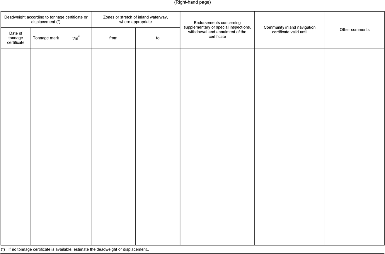
No value less than 6,6 shall be taken for 
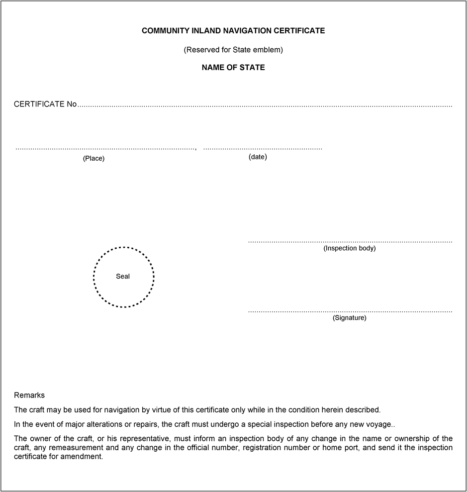


The lowest value for 
Within these formulae, apart from the terms defined previously:
I
transverse moment of inertia of water line area at Tm (m4) (for the approximation formula see paragraph 3);


a
the vertical distance between the lower edge of the opening that is first immersed in the event of heeling and the water line in the vessel's upright position (m);
b
distance from that same opening from the centre of the vessel (m);

q
sum of the volumes of the deckhouses, hatches, trunk decks and other superstructures up to a maximum height of 1,0 m above H or up to the lowest aperture in the volume under consideration, the lowest value being decisive. Parts of volumes located within a range of 0,05 L from the extremities of the vessel shall not be taken into account (m3).
3.Approximation formula for I
Where there is no sheet of hydrostatic curves available the value for the transverse moment of inertia I of the water line area may be calculated by the following approximation formulae:
(a)for vessels in the shape of a pontoon

(b)for other vessels

Article 22.04Procedure for assessing stability on board
The procedure for assessing stability may be determined by the documents referred to in Article 22.01(2).
CHAPTER 22aSPECIFIC REQUIREMENTS APPLICABLE TO CRAFT LONGER THAN 110 M
Article 22a.01Application of Part I
In addition to the requirements set out in Article 2.03(3), the inspection body which is subsequently to issue the Community certificate shall be informed by the owner or his representative before building of craft longer than 110 m, except sea-going ships, begins (building of a new vessel or extension of a vessel already in service). That inspection body shall conduct inspections during the building stage. It may dispense with inspections during the building stage if a certificate is produced before building begins to show that an approved classification society declares that it is to supervise that building.
Article 22a.02Application of Part II
In addition to Part II, Articles 22a.03 to 22a.05 shall apply to craft that are longer than 110 m.
Article 22a.03Strength
Sufficient hull strength in accordance with Article 3.02(1)(a) (longitudinal, lateral and local strength) shall be verified by a certificate issued by an approved classification society.
Article 22a.04Buoyancy and stability
1.Paragraphs 2 to 9 shall apply to craft that are longer than 110 m, with the exception of passenger vessels.
2.The proof of sufficient stability, including stability after damage, shall be verified for the most unfavourable loading condition.
The basic values for the stability calculation, the vessel's lightweight and the location of the centre of gravity, shall be determined:
either by means of a heeling experiment, or
by detailed mass and moment calculation, in which case the lightweight of the vessel shall be verified by checking the draught, with a tolerance limit of +/- 5 % between the mass determined by calculation and the displacement determined by the draught readings.
3.The proof of buoyancy after damage shall be verified for the fully laden craft.
For this purpose, calculated proof of sufficient stability shall be established for the critical intermediate stages of flooding and for the final stage of flooding. Negative values of stability in intermediate stages of flooding may be accepted by the competent authority if sufficient stability in subsequent intermediate stages is verified.
4.The following assumptions shall be taken into consideration for the damaged condition:
(a)Extent of side damage:
longitudinal extent
:
at least 0,10 L,
transverse extent
:
0,59 m,
vertical extent
:
from the base line upwards without limit;
(b)Extent of bottom damage:
longitudinal extent
:
at least 0,10 L,
transverse extent
:
3,00 m,
vertical extent
:
from the base 0,39 m upwards, the sump excepted.
(c)Any bulkheads within the damaged area shall be assumed damaged, which means that the subdivision shall be chosen so that the vessel remains afloat after the flooding of two or more adjacent compartments in the longitudinal direction.
For the main engine room only the one-compartment standard need be taken into account, i.e. the end bulkheads of the engine room shall be assumed as not damaged.
For bottom damage, adjacent athwartship compartments shall also be assumed as flooded.
(d)Permeability
Permeability shall be assumed to be 95 %.
By way of derogation from this assumption, the following permeability may be assumed:
If a calculation proves that the average permeability of any compartment is lower, the calculated value may be used.
(e)The lower edge of any non-watertight openings (e.g. doors, windows, access hatches) shall, at the final stage of flooding, be not less than 100 mm above the damaged waterline.
5.The stability after damage shall be sufficient if, on the basis of the assumptions inparagraph 4:
(a)at the final stage of flooding a safety clearance of not less than 100 mm remains and the heeling angle of the craft does not exceed 5°; or
(b)calculations in accordance with the procedure for calculation of damaged stability specified in Part 9 of the ADNR produce a positive result.
6.When cross- or down-flooding openings are provided for reduction of asymmetrical flooding, the time for equalisation shall not exceed 15 minutes, if during the intermediate stages of flooding sufficient damaged stability has been verified.
7.If openings through which undamaged compartments may additionally become flooded are capable of being closed watertight, the closing appliances shall be marked according to their operating instructions.
8.The proof by calculation in accordance with paragraphs 2 to 5 shall be considered to have been provided if damaged stability calculations in accordance with Part 9 of the ADNR, are produced with a positive result.
9.Where necessary in order to meet the requirements in paragraphs 2 or 3, the plane of maximum draught shall be re-established.
Article 22a.05Additional requirements
1.Craft longer than 110 m shall:
(a)be fitted with a multi-propeller propulsion system, with at least two independent engines of equal power and a bow thruster that is controlled from the wheelhouse and is also effective when the craft is in an unladen state; or
have a single-propeller propulsion system and a bow thruster that is controlled from the wheelhouse with its own power supply and which is also effective when the craft is in an unladen state and makes it possible for the craft to proceed under its own power in the event of a breakdown of the main propulsion system;
(b)be fitted with a radar navigation system, together with a rate-of-turn indicator in accordance with Article 7.06(1);
(c)have a permanently-installed bilge pumping system in accordance with Article 8.08;
(d)meet the requirements of Article 23.09(1)(1).
2.For craft, except passenger ships, with a length of more than 110 m, which in addition to paragraph 1
(a)are capable of being separated, in the event of an accident, in the middle third of the vessel without the use of heavy salvage equipment while the separated parts of the vessel shall remain afloat after separation;
(b)are provided with a certificate that shall be carried on board and which is issued by an approved classification society regarding the buoyancy, trim position and stability of the separate parts of the vessel, indicating the degree of loading above which buoyancy of the two parts is no longer ensured;
(c)are built as double-hull vessels in accordance with the ADNR, where for motor vessels sections 9.1.0.91 to 9.1.0.95, and for tank vessels sections 9.3.2.11.7 and 9.3.2.13 to 9.3.2.15 of Part 9 of the ADNR shall apply;
(d)are fitted with a multi-screw propulsion system in accordance withparagraph 1(a), first half sentence;
it shall be entered in item 52 of the Community certificate that they comply with all the requirements of points (a) to (d).
3.For passenger vessels with a length of more than 110 m which in addition toparagraph 1
(a)are built or converted for their highest class under the supervision of an approved classification society, in which case compliance shall be confirmed by means of a certificate issued by the classification society while current class is not necessary;
(b)either
have a double bottom with a height of at least 600 mm and subdivision to ensure that, in the event of flooding of any two adjacent watertight compartments, the vessel does not immerse lower than the margin line and a residual safety clearance of 100 mm remains,
or
have a double bottom with a height of at least 600 mm and a double hull with a distance of at least 800 mm between the side wall of the vessel and the longitudinal bulkhead;
(c)be fitted with a multi-screw propulsion system with at least two independent engines of equal power and a bow thruster system which can be operated from the wheelhouse and which operates longitudinally as well as transversely;
(d)allow the stern anchor to be operated directly from the wheelhouse;
it shall be entered in item 52 of the Community certificate that they comply with all the requirements of points (a) to (d).
Article 22a.06Application of Part IV in the event of conversion
The inspection body may apply Chapter 24 to craft converted to a length of more than 110 m only on the basis of specific recommendations by the Committee.
CHAPTER 22bSPECIFIC REQUIREMENTS APPLICABLE TO HIGH-SPEED VESSELS
Article 22b.01General
1.High-speed vessels shall not be constructed as cabin vessels.
2.The following installations are prohibited on board high-speed vessels:
(a)appliances fitted with wick burners according to Article 13.02;
(b)vaporising oil burner stoves according to Articles 13.03 and 13.04;
(c)solid-fuel heating appliances according Article 13.07;
(d)liquefied gas installations according to Chapter 14.
Article 22b.02Application of Part I
1.In addition to the provisions of Article 2.03, high-speed vessels shall be constructed and classified under the supervision and in accordance with the applicable rules of an approved classification society which has special rules for high-speed vessels. The class shall be maintained.
2.By way of derogation from Article 2.06, Community certificates issued in accordance with the provisions of this Chapter shall be valid for a maximum of five years.
Article 22b.03Application of Part II
1.Notwithstanding paragraph 2 and Article 22b.02(2), Chapters 3 to 15 shall apply to high-speed vessels, with the exception of the following provisions:
(a)Article 3.04(6), second subparagraph;
(b)Article 8.08(2), second sentence;
(c)Article 11.02(4), second and third sentences;
(d)Article 12.02(4), second sentence;
(e)Article 15.06(3)(a), second sentence.
2.By way of derogation from Article 15.02(9), and Article 15.15(7), all doors in watertight bulkheads shall be capable of being remote controlled.
3.By way of derogation from Article 6.02(1), in case of failure or malfunctioning of the steering apparatus drive unit a second independent steering apparatus drive unit or a manually operated drive unit shall come into operation without time delay.
4.In addition to the requirements of Part II, high-speed vessels shall meet the requirements of Articles 22b.04 to 22b.12.
Article 22b.04Seats and safety belts
Seats shall be available for the maximum number of passengers permitted on board. Seats shall be fitted with safety belts. Safety belts may be dispensed with where suitable impact protection is provided or where they are not required under Chapter 4, part 6, of the HSC Code 2000.
Article 22b.05Freeboard
By way of derogation from Articles 4.02 and 4.03, the freeboard shall be at least 500 mm.
Article 22b.06Buoyancy, stability and subdivision
For high-speed vessels, proper documentation shall be provided for:
(a)
buoyancy and stability characteristics adequate for safety where the craft is operated in the displacement mode, both when intact and when damaged;
(b)
stability characteristics and stabilising systems ensuring the safety of the craft when used in the dynamic buoyancy phase and the transition phase;
(c)
stability characteristics in the non-displacement and transitional modes adequate to transfer the craft safely to displacement mode in case of any system malfunction.
Article 22b.07Wheelhouse
1.Arrangement
(a)By way of derogation from Article 7.01(1), wheelhouses shall be arranged in such a way that the helmsman and a second member of the crew may at all times perform their tasks while the vessel is under way.
(b)The steering position shall be arranged so as to accommodate workstations for the persons mentioned in (a). The instruments for navigation, manoeuvring, monitoring and communication and other important operating controls shall be sufficiently close together to allow a second member of the crew as well as the helmsman to obtain the necessary information and to operate the controls and installations as necessary while seated. The following requirements shall apply in all cases:
(aa)
the steering position for the helmsman shall be arranged so as to allow radar navigation by one person.
(bb)
the second member of the crew shall have his own radar screen (slave) at his workstation and shall be able to intervene from his workstation to transmit information and control the propulsion of the vessel.
(c)The persons mentioned in (a) shall be able to operate the installations mentioned in (b) without any hindrance, including when safety belts are properly worn.
2.Unobstructed view
(a)By way of derogation from Article 7.02(2), the area of obstructed view forward of the bow for the helmsman in a seated position shall not be more than one vessel length irrespective of the amount of cargo.
(b)By way of derogation from Article 7.02(3), the total arc of blind sectors from right ahead to 22,5° abaft the beam on either side shall not exceed 20°. Each individual blind sector shall not exceed 5°. The clear sector between two blind sectors shall not be less than 10°.
3.Instruments
Instrument panels for operating and monitoring the installations mentioned in Article 22b.11 shall be in separate and clearly marked positions in the wheelhouse. This shall also apply, where appropriate, to controls for launching collective lifesaving equipment.
4.Lighting
Red light shall be used for areas or pieces of equipment which shall be lit during use.
5.Windows
Reflections shall be avoided. A means for avoiding dazzle by sunlight shall be provided.
6.Surface materials
The use of reflective surface materials in the wheelhouse shall be avoided.
Article 22b.08Additional equipment
High-speed craft shall have the following equipment:
(a)
a radar installation and rate-of-turn indicator according to Article 7.06(1),
(b)
readily accessible individual lifesaving equipment conforming to European Standard EN 395:1998 for the maximum number of persons permitted on board.
Article 22b.09Closed areas
1.General
Public spaces and accommodation and the equipment they contain shall be designed so that any person making proper use of those facilities will not suffer injury during a normal and emergency start or stop, or during manoeuvring in normal cruise and in failure or malfunction conditions.
2.Communication
(a)For the purpose of informing passengers of safety measures, all passenger vessels shall be fitted with acoustic and visual installations visible and audible to everyone on board.
(b)The installations described under (a) shall enable the boatmaster to give instructions to passengers.
(c)Every passenger shall have access to instructions for emergency situations close to their seat, including a plan of the vessel showing all exits, escape routes, emergency equipment, lifesaving equipment and instructions for the use of lifejackets.
Article 22b.10Exits and escape routes
Escape and evacuation routes shall satisfy the following requirements:
(a)
there shall be easy, safe and quick access from the steering position to spaces and accommodation accessible to the public;
(b)
escape routes leading to emergency exits shall be clearly and permanently marked;
(c)
all exits shall be properly marked. The operation of the opening mechanism shall be obvious from the outside and the inside;
(d)
the escape routes and emergency exits shall have a suitable safety guidance system;
(e)
sufficient space for a member of the crew shall be left next to exits.
Article 22b.11Fire protection and fire-fighting
1.Corridors, rooms and accommodation accessible to the public and also galleys and engine rooms shall be connected to an appropriate fire alarm system. Any fire and its location shall be indicated automatically in a place permanently manned by crew.
2.Engine rooms shall be equipped with a permanently installed fire-fighting system according to Article 10.03b.
3.Rooms and accommodation accessible to the public and their escape routes shall be equipped with a pressurised water sprinkler system according to Article 10.03a. It shall be possible to drain the used water rapidly and directly to the outside.
Article 22b.12Transitional provisions
High-speed vessels according to Article 1.01(22) which have a valid Community certificate on 31 March 2003 shall meet the following provisions of this Chapter:
(a)
Articles 22b.01, 22b.04, 22b.08, 22b.09, 22b.10, 22b.11(1)
when the Community certificate is renewed;
(b)
on 1 April 2013,
Article 22b.07(1), (3), (4), (5) and (6);
(c)
on 1 January 2023
all other provisions.
(1)
OJ L 207, 23.7.1998, p. 1. Directive as amended by Directive 98/79/EC (OJ L 331, 7.12.1998, p. 1).
(2)
OJ L 164, 30.6.1994, p. 15. Directive as last amended by Regulation (EC) No 1882/2003.
(3)
The hold sections providing free surfaces that are exposed to water arise from the longitudinal and/or tranverse water-tight compartmentalisation that forms independent sections.
Options/Cymorth
Print Options
PrintThe Whole Directive
PrintThe Whole Annex
PrintThis Part only
You have chosen to open The Whole Directive
The Whole Directive you have selected contains over 200 provisions and might take some time to download. You may also experience some issues with your browser, such as an alert box that a script is taking a long time to run.
Would you like to continue?
You have chosen to open The Whole Directive as a PDF
The Whole Directive you have selected contains over 200 provisions and might take some time to download.
Would you like to continue?
You have chosen to open The Whole Annex
The Whole Annex you have selected contains over 200 provisions and might take some time to download. You may also experience some issues with your browser, such as an alert box that a script is taking a long time to run.
Would you like to continue?
You have chosen to open The Whole Annex as a PDF
The Whole Annex you have selected contains over 200 provisions and might take some time to download.
Would you like to continue?
You have chosen to open the Whole Directive
The Whole Directive you have selected contains over 200 provisions and might take some time to download. You may also experience some issues with your browser, such as an alert box that a script is taking a long time to run.
Would you like to continue?
You have chosen to open Schedules only
Y Rhestrau you have selected contains over 200 provisions and might take some time to download. You may also experience some issues with your browser, such as an alert box that a script is taking a long time to run.
Would you like to continue?
Mae deddfwriaeth ar gael mewn fersiynau gwahanol:
Y Diweddaraf sydd Ar Gael (diwygiedig):Y fersiwn ddiweddaraf sydd ar gael o’r ddeddfwriaeth yn cynnwys newidiadau a wnaed gan ddeddfwriaeth ddilynol ac wedi eu gweithredu gan ein tîm golygyddol. Gellir gweld y newidiadau nad ydym wedi eu gweithredu i’r testun eto yn yr ardal ‘Newidiadau i Ddeddfwriaeth’.
Gwreiddiol (Fel y’i mabwysiadwyd gan yr UE): Mae'r wreiddiol version of the legislation as it stood when it was first adopted in the EU. No changes have been applied to the text.
Dewisiadau Agor
Dewisiadau gwahanol i agor deddfwriaeth er mwyn gweld rhagor o gynnwys ar y sgrin ar yr un pryd
Rhagor o Adnoddau
Gallwch wneud defnydd o ddogfennau atodol hanfodol a gwybodaeth ar gyfer yr eitem ddeddfwriaeth o’r tab hwn. Yn ddibynnol ar yr eitem ddeddfwriaeth sydd i’w gweld, gallai hyn gynnwys:
- y PDF print gwreiddiol y fel adopted version that was used for the EU Official Journal
- rhestr o newidiadau a wnaed gan a/neu yn effeithio ar yr eitem hon o ddeddfwriaeth
- pob fformat o’r holl ddogfennau cysylltiedig
- slipiau cywiro
- dolenni i ddeddfwriaeth gysylltiedig ac adnoddau gwybodaeth eraill
Rhagor o Adnoddau
Defnyddiwch y ddewislen hon i agor dogfennau hanfodol sy’n cyd-fynd â’r ddeddfwriaeth a gwybodaeth am yr eitem hon o ddeddfwriaeth. Gan ddibynnu ar yr eitem o ddeddfwriaeth sy’n cael ei gweld gall hyn gynnwys:
- y PDF print gwreiddiol y fel adopted fersiwn a ddefnyddiwyd am y copi print
- slipiau cywiro
liciwch ‘Gweld Mwy’ neu ddewis ‘Rhagor o Adnoddau’ am wybodaeth ychwanegol gan gynnwys
- rhestr o newidiadau a wnaed gan a/neu yn effeithio ar yr eitem hon o ddeddfwriaeth
- manylion rhoi grym a newid cyffredinol
- pob fformat o’r holl ddogfennau cysylltiedig
- dolenni i ddeddfwriaeth gysylltiedig ac adnoddau gwybodaeth eraill
 Mae’r holl gynnwys ar gael dan Drwydded Llywodraeth Agored v3.0 ac eithrio ble nodir yn wahanol. Yn ychwanegol mae’r safle hwn â chynnwys sy’n deillio o EUR-Lex, a ailddefnyddiwyd dan delerau Penderfyniad y Comisiwn 2011/833/EU ar ailddefnyddio dogfennau o sefydliadau’r UE. Am ragor o wybodaeth gweler ddatganiad cyhoeddus Swyddfa Gyhoeddiadau’r UE ar ailddefnyddio.