- Y Diweddaraf sydd Ar Gael (Diwygiedig)
- Pwynt Penodol mewn Amser (13/07/2009)
- Gwreiddiol (Fel y’i mabwysiadwyd gan yr UE)
Directive 2009/64/EC of the European Parliament and of the Council (repealed)Dangos y teitl llawn
Directive 2009/64/EC of the European Parliament and of the Council of 13 July 2009 on the suppression of radio interference produced by agricultural or forestry tractors (electromagnetic compatibility) (codified version) (Text with EEA relevance) (repealed)
You are here:
- Cyfarwyddebau yn deillio o’r UE
- 2009 No. 64
- Whole Directive
- Blaenorol
- Nesaf

Pa Fersiwn
Nodweddion Uwch
- Dangos Graddfa Ddaearyddol(e.e. Lloegr, Cymru, Yr Alban aca Gogledd Iwerddon)
- Dangos Llinell Amser Newidiadau
Rhagor o Adnoddau
PDF o Fersiynau Diwygiedig
- ddiwygiedig 01/07/20133.88 MB
- ddiwygiedig 09/09/20093.82 MB
Deddfwriaeth yn deillio o’r UE
Pan adawodd y DU yr UE, cyhoeddodd legislation.gov.uk ddeddfwriaeth yr UE a gyhoeddwyd gan yr UE hyd at ddiwrnod cwblhau’r cyfnod gweithredu (31 Rhagfyr 2020 11.00 p.m.). Ar legislation.gov.uk, mae'r eitemau hyn o ddeddfwriaeth yn cael eu diweddaru'n gyson ag unrhyw ddiwygiadau a wnaed gan y DU ers hynny.


Mae'r eitem hon o ddeddfwriaeth yn tarddu o'r UE
Mae legislation.gov.uk yn cyhoeddi fersiwn y DU. Mae EUR-Lex yn cyhoeddi fersiwn yr UE. Mae Archif Gwe Ymadael â’r UE yn rhoi cipolwg ar fersiwn EUR-Lex o ddiwrnod cwblhau’r cyfnod gweithredu (31 Rhagfyr 2020 11.00 p.m.).
Changes over time for: Directive 2009/64/EC of the European Parliament and of the Council (repealed)
Version Superseded: 09/09/2009
Status:
Cyhoeddir Cyfarwyddebau’r UE ar y wefan hon i gynorthwyo croesgyfeirio o ddeddfwriaeth y DU. Ers diwrnod cwblhau’r cyfnod gweithredu (31 Rhagfyr 2020 11.00 p.m.) nid oes unrhyw ddiwygiadau wedi'u cymhwyso i'r fersiwn hon.
Directive 2009/64/EC of the European Parliament and of the Council
of 13 July 2009
on the suppression of radio interference produced by agricultural or forestry tractors (electromagnetic compatibility)
(codified version)
(Text with EEA relevance) (repealed)
THE EUROPEAN PARLIAMENT AND THE COUNCIL OF THE EUROPEAN UNION,
Having regard to the Treaty establishing the European Community, and in particular Article 95 thereof,
Having regard to the proposal from the Commission,
Having regard to the opinion of the European Economic and Social Committee(1),
Acting in accordance with the procedure laid down in Article 251 of the Treaty(2),
Whereas:
(1) Council Directive 75/322/EEC of 20 May 1975 on the suppression of radio interference produced by agricultural or forestry tractors (electromagnetic compatibility)(3) has been substantially amended several times(4). In the interests of clarity and rationality the said Directive should be codified.
(2) Directive 75/322/EEC is one of the separate Directives of the EC type-approval system provided for in Council Directive 74/150/EEC of 4 March 1974 on the approximation of the laws of the Member States relating to the type-approval of wheeled agricultural or forestry tractors, as replaced by Directive 2003/37/EC of the European Parliament and of the Council of 26 May 2003 on type-approval of agricultural or forestry tractors, their trailers and interchangeable towed machinery, together with their systems, components and separate technical units(5), and lays down technical prescriptions concerning the suppression of radio interference produced by agricultural or forestry tractors (electromagnetic compatibility). Those technical prescriptions concern the approximation of the laws of the Member States to enable the EC type-approval procedure provided for in Directive 2003/37/EC to be applied in respect of each type of tractor. Consequently, the provisions laid down in Directive 2003/37/EC relating to agricultural and forestry tractors, their trailers and interchangeable towed machinery, together with their systems, components and separate technical units apply to this Directive.
(3) This Directive should be without prejudice to the obligations of the Member States relating to the time-limits for transposition into national law and application of the Directives set out in Annex XII, Part B,
HAVE ADOPTED THIS DIRECTIVE:
Article 1U.K.
For the purposes of this Directive, ‘vehicle’ means any vehicle as defined in Article 2(d) of Directive 2003/37/EC.
Article 2U.K.
1.Member States may not, on grounds relating to electromagnetic compatibility:
refuse to grant EC type-approval or national type-approval in respect of any given type of vehicle,
refuse to grant EC component or technical unit type-approval in respect of any given type of component or separate technical unit,
prohibit the registration, sale or entry into service of vehicles,
prohibit the sale or use of components or separate technical units,
if the vehicles, components or separate technical units comply with the requirements of this Directive.
2.Member States
may not grant EC vehicle type-approval, EC component type-approval or EC separate technical unit type-approval, and
may refuse to grant national type-approval,
for any type of vehicle, component or separate technical unit, if the requirements of this Directive are not fulfilled.
3.Paragraph 2 shall not apply to vehicle types approved before 1 October 2002 pursuant to Council Directive 77/537/EEC of 28 June 1977 on the approximation of the laws of the Member States relating to the measures to be taken against the emission of pollutants from diesel engines for use in wheeled agricultural or forestry tractors(6) or to any subsequent extensions to those approvals.
4.Member States:
shall consider certificates of conformity which accompany new vehicles in accordance with Directive 2003/37/EC to be not valid for the purposes of Article 7(1) of that Directive, and
may refuse the sale and entry into service of new electrical or electronic sub-assemblies as components or separate technical units,
if the requirements of this Directive are not fulfilled.
5.Without prejudice to paragraphs 2 and 4, in the case of replacement parts, Member States shall continue to grant EC type-approval and to permit the sale and entry into service of components or separate technical units intended for use on vehicle types which have been approved before 1 October 2002 pursuant to Directive 75/322/EEC or Directive 77/537/EEC and, where applicable, subsequent extensions to those approvals.
Article 3U.K.
This Directive shall constitute ‘another Community directive’ for the purposes of Article 1(4) of Directive 2004/108/EC of the European Parliament and of the Council of 15 December 2004 on the approximation of the laws of the Member States relating to electromagnetic compatibility(7).
Article 4U.K.
The amendments necessary to adapt to technical progress the requirements of Annexes I to XI shall be adopted in accordance with the procedure referred to in Article 20(3) of Directive 2003/37/EC.
Article 5U.K.
Member States shall communicate to the Commission the text of the main provisions of national law which they adopt in the field covered by this Directive.
Article 6U.K.
Directive 75/322/EEC, as amended by the acts listed in Annex XII, Part A, is repealed, without prejudice to the obligations of the Member States relating to the time-limits for transposition into national law and application of the Directives set out in Annex XII, Part B.
References to the repealed Directive shall be construed as references to this Directive and shall be read in accordance with the correlation table in Annex XIII.
Article 7U.K.
This Directive shall enter into force on the twentieth day following its publication in the Official Journal of the European Union.
It shall apply from 1 January 2010.
Article 8U.K.
This Directive is addressed to the Member States.
Done at Brussels, 13 July 2009.
For the European Parliament
The President
H.- G. Pöttering
For the Council
The President
E. Erlandsson
LIST OF ANNEXESU.K.
| ANNEX I | REQUIREMENTS TO BE MET BY VEHICLES AND ELECTRICAL/ELECTRONIC SUB-ASSEMBLIES FITTED TO A VEHICLE | ||
| Appendix 1 | Vehicle broadband reference limits: Antenna-vehicle separation: 10 m | ||
| Appendix 2 | Vehicle broadband reference limits: Antenna-vehicle separation: 3 m | ||
| Appendix 3 | Vehicle narrowband reference limits: Antenna-vehicle separation: 10 m | ||
| Appendix 4 | Vehicle narrowband reference limits: Antenna-vehicle separation: 3 m | ||
| Appendix 5 | Broadband reference limits of electrical/electronic sub-assembly | ||
| Appendix 6 | Narrowband reference limits of electrical/electronic sub-assembly | ||
| Appendix 7 | Example of the EC type-approval mark | ||
| ANNEX II | Information document No … pursuant to Annex I to Directive 2003/37/EC relating to EC type-approval of an agricultural or forestry tractor concerning electromagnetic compatibility (Directive 2009/64/EC) | ||
| Appendix 1 | |||
| Appendix 2 | |||
| ANNEX III | Information document No … relating to EC type-approval of an electrical/electronic sub-assembly (ESA) with respect to electromagnetic compatibility (Directive 2009/64/EC) | ||
| Appendix 1 | |||
| Appendix 2 | |||
| ANNEX IV | MODEL: EC TYPE-APPROVAL CERTIFICATE ‘VEHICLE’ | ||
| Appendix to EC type-approval certificate No … concerning the type-approval of a vehicle with regard to Directive 2009/64/EC | |||
| ANNEX V | MODEL: EC TYPE-APPROVAL CERTIFICATE ‘ESA’ | ||
| Appendix to EC type-approval certificate No … concerning the type-approval of an electrical/electronic sub-assembly with regard to Directive 2009/64/EC | |||
| ANNEX VI | METHOD OF MEASUREMENT OF RADIATED BROADBAND ELECTROMAGNETIC EMISSIONS FROM VEHICLES | ||
| Appendix 1 | Figure 1 | TRACTOR TEST AREA | |
| Figure 2 | POSITION OF ANTENNA RELATIVE TO TRACTOR | ||
| ANNEX VII | METHOD OF MEASUREMENT OF RADIATED NARROWBAND ELECTROMAGNETIC EMISSIONS FROM VEHICLES | ||
| ANNEX VIII | METHOD OF TESTING FOR IMMUNITY OF VEHICLES TO ELECTROMAGNETIC RADIATION | ||
| Appendix 1 | |||
| Appendix 2 | |||
| Appendix 3 | Characteristics of test signal to be generated | ||
| ANNEX IX | METHOD OF MEASUREMENT OF RADIATED BROADBAND ELECTROMAGNETIC EMISSIONS FROM ELECTRICAL/ELECTRONIC SUB-ASSEMBLIES | ||
| Appendix 1 | Electrical/electronic sub-assembly test area boundary | ||
| Appendix 2 | Figure 1 | Radiated electromagnetic emissions from an ESA test layout (General plan view) | |
| Figure 2 | Radiated electromagnetic emissions from an ESA view of test bench plane of longitudinal symmetry | ||
| ANNEX X | METHOD OF MEASUREMENT OF RADIATED NARROWBAND ELECTROMAGNETIC EMISSIONS FROM ELECTRICAL/ELECTRONIC SUB-ASSEMBLIES | ||
| ANNEX XI | METHOD(S) OF TESTING FOR IMMUNITY OF ELECTRICAL/ELECTRONIC SUB-ASSEMBLIES TO ELECTROMAGNETIC RADIATION | ||
| Appendix 1 | Figure 1 | 150 mm stripline testing | |
| Figure 2 | 150 mm stripline testing | ||
| Figure 3 | 800 mm stripline testing | ||
| Figure 4 | 800 mm stripline dimensions | ||
| Appendix 2 | Example of BCI test configuration | ||
| Appendix 3 | Figure 1 | TEM cell testing | |
| Figure 2 | Design of rectangular TEM cell | ||
| Figure 3 | Typical TEM cell dimensions | ||
| Appendix 4 | Free field ESA immunity test | ||
| Figure 1 | Test layout (general plan view) | ||
| Figure 2 | View of test bench plane of longitudinal symmetry | ||
| ANNEX XII | PART A: Repealed Directive with list of its successive amendments | ||
| PART B: List of time-limits for transposition into national law and application | |||
| ANNEX XIII | Correlation table | ||
ANNEX IREQUIREMENTS TO BE MET BY VEHICLES AND ELECTRICAL/ELECTRONIC SUB-ASSEMBLIES FITTED TO A VEHICLE
1.SCOPEU.K.
1.1.This Directive applies to the electromagnetic compatibility of vehicles covered by Article 1. It also applies to electrical or electronic separate technical units intended to be fitted to the vehicles.U.K.
2.DEFINITIONSU.K.
2.1.For the purposes of this DirectiveU.K.
2.1.1.‘Electromagnetic compatibility’ means the ability of a vehicle or component(s) or separate technical unit(s) to function satisfactorily in its electromagnetic environment without introducing intolerable electromagnetic disturbances to anything in that environment.U.K.
2.1.2.‘Electromagnetic disturbance’ means any electromagnetic phenomenon which may degrade the performance of a vehicle or component(s) or separate technical unit(s). An electromagnetic disturbance may be electromagnetic noise, an unwanted signal or a change in the propagation medium itself.U.K.
2.1.3.‘Electromagnetic immunity’ means the ability of a vehicle or component(s) or separate technical unit(s) to perform without degradation of performance in the presence of specified electromagnetic disturbances.U.K.
2.1.4.‘Electromagnetic environment’ means the totality of electromagnetic phenomena existing at a given location.U.K.
2.1.5.‘Reference limit’ means the nominal level to which type-approval and conformity of production limit values are referenced.U.K.
2.1.6.‘Reference antenna’ for the frequency range 20 to 80 MHz: means a shortened balanced dipole being a half wave resonant dipole at 80 MHz, and for the frequency range above 80 MHz: means a balanced half wave resonant dipole tuned to the measurement frequency.U.K.
2.1.7.‘Broadband emission’ means an emission which has a bandwidth greater than that of a particular measuring apparatus or receiver.U.K.
2.1.8.‘Narrowband emission’ means an emission which has a bandwidth less than that of a particular measuring apparatus or receiver.U.K.
2.1.9.‘Electrical/electronic system’ means (an) electrical and/or electronic device(s) or set(s) of devices together with any associated electrical connections which form part of a vehicle but which are not intended to be type approved separately from the vehicle.U.K.
2.1.10.‘Electrical/electronic sub-assembly’ (ESA) means an electrical and/or electronic device or set(s) of devices intended to be part of a vehicle, together with any associated electrical connections and wiring, which performs one or more specialised functions. An ESA may be approved at the request of a manufacturer as either a ‘component’ or a ‘separate technical unit (STU)’ (see Article 4(1)(c) of Directive 2003/37/EC).U.K.
2.1.11.
‘Vehicle type’ in relation to electromagnetic compatibility means vehicles which do not differ essentially in such respects as:U.K.
2.1.11.1.the overall size and shape of the engine compartment;U.K.
2.1.11.2.the general arrangement of the electrical and/or electronic components and the general wiring arrangement;U.K.
2.1.11.3.the primary material of which the body or shell (if applicable) of the vehicle is constructed (for example, a steel, aluminium or fibreglass body shell); the presence of panels of different material does not change the vehicle type provided the primary material of the body is unchanged; however, such variations must be notified.U.K.
2.1.12.
An ‘ESA type’ in relation to electromagnetic compatibility means ESAs which do not differ in such essential respects as:U.K.
2.1.12.1.the function performed by the ESA;U.K.
2.1.12.2.the general arrangement of the electrical and/or electronic components, if applicable.U.K.
3.APPLICATION FOR EC TYPE-APPROVALU.K.
3.1.Approval of a vehicle typeU.K.
3.1.1.The application for approval of a vehicle type, with regard to its electromagnetic compatibility pursuant to Article 4(1) of Directive 2003/37/EC shall be submitted by the vehicle manufacturer.U.K.
3.1.2.A model for the information document is set out in Annex II.U.K.
3.1.3.The vehicle manufacturer shall draw up a schedule describing all projected combinations of relevant vehicle electrical/electronic systems or ESAs, body styles(8), variations in body material(8), general wiring arrangements, engine variations, left-hand/right-hand drive versions and wheelbase versions. Relevant vehicle electrical/electronic systems or ESAs are those which may emit significant broadband or narrowband radiation and/or those which are involved in the driver's direct control (see point 6.4.2.3) of the vehicle.U.K.
3.1.4.A representative vehicle shall be selected from this schedule for the purpose of being tested, in mutual agreement between the manufacturer and the competent authority. This vehicle shall represent the vehicle type (see Appendix 1 of Annex II). The choice of vehicle shall be based on the electrical/electronic systems offered by the manufacturer. One more vehicle may be selected from this schedule for the purpose of being tested if it is considered by mutual agreement between the manufacturer and the competent authority that different electrical/electronic systems are included which are likely to have a significant effect on the vehicle's electromagnetic compatibility compared with the first representative vehicle.U.K.
3.1.5.The choice of the vehicle(s) in conformity with point 3.1.4 is limited to vehicle/electrical/electronic system combinations intended for actual production.U.K.
3.1.6.The manufacturer may supplement the application with a report from tests which have been carried out. Any such data provided may be used by the approval authority for the purpose of drawing up the EC type-approval certificate.U.K.
3.1.7.If the technical service responsible for the type-approval test carries out the test itself, then a vehicle representative of the type to be approved, according to point 3.1.4 shall be provided.U.K.
3.2.Approval of a type of ESAU.K.
3.2.1.The application for approval of a type of ESA with regard to its electromagnetic compatibility pursuant to Article 4(1) of Directive 2003/37/EC shall be submitted by the vehicle manufacturer or by the manufacturer of the ESA.U.K.
3.2.2.A model for the information document is set out in Annex III.U.K.
3.2.3.The manufacturer may supplement the application with a report from tests which have been carried out. Any such data provided may be used by the approval authority for the purpose of drawing up the EC type-approval certificate.U.K.
3.2.4.If the technical service responsible for the type-approval test carries out the test itself, then a sample of the ESA system representative of the type to be approved shall be provided, if necessary, after discussion with the manufacturer on, for example, possible variations in the layout, the number of components and the number of sensors. If the technical service deems it necessary, it may select a further sample.U.K.
3.2.5.The sample(s) must be clearly and indelibly marked with the manufacturer's trade name or mark and the type designation.U.K.
3.2.6.Where applicable, any restrictions on use shall be identified. Any such restrictions shall be included in the information document set out in Annex III and/or in the EC type-approval certificate set out in Annex V.U.K.
4.TYPE-APPROVALU.K.
4.1.Routes to type-approvalU.K.
4.1.1.Type-approval of a vehicleU.K.
The following alternative routes to type-approval of a vehicle may be used at the discretion of the vehicle manufacturer.U.K.
4.1.1.1.Approval of a vehicle installationU.K.
A vehicle installation may achieve type-approval directly by following the provisions laid down in point 6. If this route is chosen by a vehicle manufacturer, no separate testing of electrical/electronic systems or ESAs is required.
4.1.1.2.Approval of vehicle type by testing of individual ESAsU.K.
A vehicle manufacturer may obtain approval for the vehicle by demonstrating to the approval authority that all the relevant (see point 3.1.3) electrical/electronic systems or ESAs have individually been approved in accordance with this Directive and have been installed in accordance with any conditions attached thereto.
4.1.1.3.A manufacturer, if he wishes, may obtain approval pursuant to this Directive if the vehicle has no equipment of the type which is subject to immunity or emission tests. The vehicle shall have no systems as specified in point 3.1.3 (immunity) and no spark ignition equipment. Such approvals shall not require testing.U.K.
4.1.2.Type-approval of an ESAU.K.
Type-approval may be granted to an ESA to be fitted either to any vehicle type or to a specific vehicle type or types requested by the manufacturer. ESAs involved in the direct control of vehicles will normally receive type-approval in conjunction with a vehicle manufacturer.
4.2.Granting of type-approvalU.K.
4.2.1.VehicleU.K.
4.2.1.1.If the representative vehicle fulfils the requirements of this Directive, EC type-approval pursuant to Article 4 of Directive 2003/37/EC shall be granted.U.K.
4.2.1.2.A model for the EC type-approval certificate is set out in Annex IV.U.K.
4.2.2.ESAU.K.
4.2.2.1.If the representative ESA system(s) fulfil(s) the requirements of this Directive, EC type-approval pursuant to Article 4 of Directive 2003/37/EC shall be granted.U.K.
4.2.2.2.A model for the EC type-approval certificate is given in Annex V.U.K.
4.2.3.In order to draw up the certificates referred to in point 4.2.1.2 or 4.2.2.2, the competent authority of the Member State granting the approval may use a report prepared by an approved or recognised laboratory or in accordance with the provisions of this Directive.U.K.
4.3.Amendments to approvalsU.K.
4.3.1.In the case of amendments to approvals granted pursuant to this Directive, the provisions of Article 5(2) and (3) of Directive 2003/37/EC shall apply.U.K.
4.3.2.Amendment of a vehicle type-approval by ESA addition or substitutionU.K.
4.3.2.1.Where a vehicle manufacturer has obtained approval for a vehicle installation and wishes to fit an additional or substitutional electrical/electronic system or ESA which has already received approval pursuant to this Directive, and which will be installed in accordance with any conditions attached thereto, the vehicle approval may be amended without further testing. The additional or substitutional electrical/electronic system or ESA shall be considered as part of the vehicle for conformity of production purposes.U.K.
4.3.2.2.Where the additional or substitutional part(s) has (have) not received approval pursuant to this Directive, and if testing is considered necessary, the whole vehicle shall be deemed to comply if the new or revised part(s) can be shown to comply with the relevant requirements of point 6 or if, in a comparative test, the new part can be shown not to be likely to adversely affect compliance of the vehicle type.U.K.
4.3.2.3.The addition by a vehicle manufacturer to an approved vehicle of standard domestic or business equipment, other than mobile communication equipment(9) which complies with Directive 2004/108/EC, and is installed according to the recommendations of the equipment and vehicle manufacturers, or the substitution or removal thereof, shall not invalidate the vehicle approval. This shall not preclude vehicle manufacturers fitting communication equipment with suitable installations guidelines developed by the vehicle manufacturer and/or manufacturer(s) of such communication equipment. The vehicle manufacturer shall provide evidence (if requested by the test authority) that vehicle performance is not adversely affected by such transmitters. This may be a statement that the power levels and installation are such that the immunity levels of this Directive offer sufficient protection when subject to transmission alone, namely excluding transmission in conjunction with the tests specified in point 6. This Directive does not authorise the use of a communication transmitter when other requirements on such equipment or its use apply. A vehicle manufacturer may refuse to install in his vehicle standard domestic or business equipment which complies with Directive 2004/108/EC.U.K.
5.MARKINGU.K.
5.1.Every ESA conforming to a type approved pursuant to this Directive shall bear an EC type-approval mark.U.K.
5.2.This mark shall consist of a rectangle surrounding the letter ‘e’ followed by the distinguishing number of the Member State which has granted EC type-approval:U.K.
1 for Germany; 2 for France; 3 for Italy; 4 for the Netherlands; 5 for Sweden; 6 for Belgium; 7 for Hungary; 8 for the Czech Republic; 9 for Spain; 11 for the United Kingdom; 12 for Austria; 13 for Luxembourg; 17 for Finland; 18 for Denmark; 19 for Romania; 20 for Poland; 21 for Portugal; 23 for Greece; 24 for Ireland; 26 for Slovenia; 27 for Slovakia; 29 for Estonia; 32 for Latvia; 34 for Bulgaria; 36 for Lithuania; 49 for Cyprus; 50 for Malta.
It must also include in the vicinity of the rectangle the four-digit sequential number (with leading zeros as applicable) — hereinafter referred to as the ‘base approval number’ — contained in Section 4 of the type-approval number shown on the EC type-approval certificate issued for the type of device in question (see Annex V), preceded by the two figures indicating the sequence number assigned to the most recent major technical amendment to Directive 75/322/EEC, as replaced by this Directive, on the date EC component type-approval was granted.
5.3.The EC type-approval mark must be affixed to the main part of the ESA (for example the electronic control unit) in such a way as to be clearly legible and indelible.U.K.
5.4.An example of the EC type-approval mark is set out in Appendix 7.U.K.
5.5.No marking is required for electrical/electronic systems included in vehicle types approved by this Directive.U.K.
5.6.Markings on ESAs in compliance with point 5.3 need not be visible when the ESA is installed in a vehicle.U.K.
6.SPECIFICATIONSU.K.
6.1.General specificationU.K.
6.1.1.A vehicle (and its electrical/electronic system(s) or ESAs) shall be so designed, constructed and fitted as to enable the vehicle, in normal conditions of use, to comply with the requirements of this Directive.U.K.
6.2.Specifications concerning broadband electromagnetic radiation from vehicles fitted with spark ignitionU.K.
6.2.1.Method of measurementU.K.
The electromagnetic radiation generated by the vehicle representative of its type shall be measured using the method described in Annex VI at either of the defined antenna distances. The choice shall be made by the vehicle manufacturer.
6.2.2.Vehicle broadband reference limitsU.K.
6.2.2.1.If measurements are made using the method described in Annex VI using a vehicle-to-antenna spacing of 10,0 ± 0,2 m, the radiation reference limits shall be 34 dB microvolts/m (50 microvolts/m) in the 30 to 75 MHz frequency band and 34 to 45 dB microvolts/m (50 to 180 microvolts/m) in the 75 to 400 MHz frequency band, this limit increasing logarithmically (linearly) with frequencies above 75 MHz as shown in Appendix 1 of this Annex. In the 400 to 1 000 MHz frequency band the limit remains constant at 45 dB microvolts/m (180 microvolts/m).U.K.
6.2.2.2.If measurements are made using the method described in Annex VI using a vehicle-to-antenna spacing of 3,0 ± 0,05 m, the radiation reference limits shall be 44 dB microvolts/m (160 microvolts/m) in the 30 to 75 MHz frequency band and 44 to 55 dB microvolts/m (160 to 562 microvolts/m) in the 75 to 400 MHz frequency band, this limit increasing logarithmically (linearly) with frequencies above 75 MHz as shown in Appendix 2 of this Annex. In the 400 to 1 000 MHz frequency band the limit remains constant at 55 dB microvolts/m (562 microvolts/m).U.K.
6.2.2.3.On the vehicle representative of its type, the measured values, expressed in dB microvolts/m (microvolts/m), shall be at least 2,0 dB (20 %) below the reference limits.U.K.
6.3.Specifications concerning narrowband electromagnetic radiation from vehiclesU.K.
6.3.1.Method of measurementU.K.
The electromagnetic radiation generated by the vehicle representative of its type shall be measured using the method described in Annex VII at either of the defined antenna distances. The choice shall be made by the vehicle manufacturer.
6.3.2.Vehicle narrowband reference limitsU.K.
6.3.2.1.If measurements are made using the method described in Annex VII using a vehicle-to-antenna spacing of 10,0 ± 0,2 m, the radiation-reference limits shall be 24 dB microvolts/m (16 microvolts/m) in the 30 to 75 MHz frequency band and 24 to 35 dB microvolts/m (16 to 56 microvolts/m) in the 75 to 400 MHz frequency band, this limit increasing logarithmically (linearly) with frequencies above 75 MHz as shown in Appendix 3 of this Annex. In the 400 to 1 000 MHz frequency band the limit remains constant at 35 dB microvolts/m (56 microvolts/m).U.K.
6.3.2.2.If measurements are made using the method described in Annex VII using a vehicle-to-antenna spacing of 3,0 ± 0,05 m, the radiation reference limit shall be 34 dB microvolts/m (50 microvolts/m) in the 30 to 75 MHz frequency band and 34 to 45 dB microvolts/m (50 to 180 microvolts/m) in the 75 to 400 MHz frequency band, this limit increasing logarithmically (linearly) with frequencies above 75 MHz as shown in Appendix 4 of this Annex. In the 400 to 1 000 MHz frequency band the limit remains constant at 45 dB microvolts/m (180 microvolts/m).U.K.
6.3.2.3.On the vehicle representative of its type, the measured values, expressed in dB microvolts/m (microvolts/m), shall be at least 2,0 dB (20 %) below the reference limit.U.K.
6.3.2.4.Notwithstanding the limits defined in points 6.3.2.1, 6.3.2.2 and 6.3.2.3 of this Annex, if, during the initial step described in point 1.3 of Annex VII, the signal strength measured at the vehicle broadcast radio antenna is less than 20 dB microvolts/m (10 microvolts/m) over the frequency range 88 to 108 MHz, then the vehicle shall be deemed to comply with the limits for narrowband emissions and no further testing will be required.U.K.
6.4.Specifications concerning immunity of vehicles to electromagnetic radiationU.K.
6.4.1.Method of testingU.K.
The immunity to electromagnetic radiation of the vehicle representative of its type shall be tested by the method described in Annex VIII.
6.4.2.Vehicle immunity reference limitsU.K.
6.4.2.1.If tests are made using the method described in Annex VIII, the field strength reference level shall be 24 volts/m rms in over 90 % of the 20 to 1 000 MHz frequency band and 20 volts/m rms over the whole 20 to 1 000 MHz frequency band.U.K.
6.4.2.2.The vehicle representative of its type shall be considered as complying with immunity requirements if, during the tests performed in accordance with Annex VIII, and subjected to a field strength, expressed in volts/m, of 25 % above the reference level, there shall be no abnormal change in the speed of the driven wheels of the vehicle, no degradation of performance which would cause confusion to other road users, and no degradation in the driver's direct control of the vehicle which could be observed by the driver or other road user.U.K.
6.4.2.3.The driver's direct control of the vehicle is exercised by means of, for example, steering, braking, or engine speed control.U.K.
6.5.Specification concerning broadband electromagnetic interference generated by ESAsU.K.
6.5.1.Method of measurementU.K.
The electromagnetic radiation generated by the ESA representative of its type shall be measured by the method described in Annex IX.
6.5.2.ESA broadband reference limitsU.K.
6.5.2.1.If measurements are made using the method described in Annex IX, the radiation reference limits shall be 64 to 54 dB microvolts/m(1 600 to 500 microvolts/m) in the 30 to 75 MHz frequency band, this limit decreasing logarithmically (linearly) with frequencies above 30 MHz, and 54 to 65 dB microvolts/m (500 to 1 800 microvolts/m) in the 75 to 400 MHz band, this limit increasing logarithmically (linearly) with frequencies above 75 MHz as shown in Appendix 5 of this Annex. In the 400 to 1 000 MHz frequency band the limit remains constant at 65 dB microvolts/m (1 800 microvolts/m).U.K.
6.5.2.2.On the ESA representative of its type, the measured values, expressed in dB microvolts/m, (microvolts/m) shall be at least 2,0 dB (20 %) below the reference limits.U.K.
6.6.Specifications concerning narrowband electromagnetic interference generated by ESAsU.K.
6.6.1.Method of measurementU.K.
The electromagnetic radiation generated by the ESA representative of its type shall be measured by the method described in Annex X.
6.6.2.ESA narrowband reference limitsU.K.
6.6.2.1.If measures are made using the method described in Annex X, the radiation reference limits shall be 54 to 44 dB microvolts/m (500 to 160 microvolts/m) in the 30 to 75 MHz frequency band, this limit decreasing logarithmically (linearly) with frequencies above 30 MHz, and 44 to 55 dB microvolts/m (160 to 560 microvolts/m) in the 75 to 400 MHz band, this limit increasing logarithmically (linearly) with frequencies above 75 MHz as shown in Appendix 6 of this Annex. In the 400 to 1 000 MHz frequency band the limit remains constant at 55 dB microvolts/m (560 microvolts/m).U.K.
6.6.2.2.On the ESA representative of its type, the measured value, expressed in dB microvolts/m (microvolts/m) shall be at least 2,0 dB (20 %) below the reference limits.U.K.
6.7.Specifications concerning immunity of ESAs to electromagnetic radiationU.K.
6.7.1.Method(s) of testingU.K.
The immunity to electromagnetic radiation of the ESA representative of its type shall be tested by the method(s) chosen from those described in Annex XI.
6.7.2.ESA immunity reference limitsU.K.
6.7.2.1.If tests are made using the methods described in Annex XI, the immunity test reference levels shall be 48 volts/m for the 150 mm stripline testing method, 12 volts/m for the 800 mm stripline testing method, 60 volts/m for the transverse electromagnetic mode (TEM) cell testing method, 48 mA for the bulk current injection (BCI) testing method and 24 volts/m for the free field testing method.U.K.
6.7.2.2.On the ESA representative of its type at a field strength or current expressed in appropriate linear units 25 % above the reference limit, the ESA shall not exhibit any malfunction which would cause any degradation of performance which could cause confusion to other road users or any degradation in the driver's direct control of a vehicle fitted with the system which could be observed by the driver or other road user.U.K.
7.CONFORMITY OF PRODUCTIONU.K.
7.1.Conformity of production with regard to the electromagnetic compatibility of the vehicle or component of separate technical unit shall be checked on the basis of the data contained in the EC type-approval certificate(s) set out in Annex IV and/or Annex V as appropriate.U.K.
7.2.If the conformity of a vehicle, component or STU taken from the series is being verified, production shall be deemed to conform to the requirements of this Directive in relation to broadband radiated emissions and narrowband radiated emissions if the levels measured do not exceed by more than 2 dB, (25 %) the reference limits prescribed in points 6.2.2.1, 6.2.2.2, 6.3.2.1 and 6.3.2.2 (as appropriate).U.K.
7.3.If the conformity of a vehicle, component or STU taken from the series is being verified, production shall be deemed to conform to the requirements of this Directive in relation to immunity to electromagnetic radiation if the vehicle, component or STU does not exhibit any degradation relating to the direct control of the vehicle which could be observed by the driver or other road user when the vehicle, component or STU is in the state defined in point 4 of Annex VIII and subjected to a field strength, expressed in volts/m, up to 80 % of the reference limits prescribed in point 6.4.2.1 of this Annex.U.K.
8.EXCEPTIONSU.K.
8.1.Where a vehicle or electrical/electronic system or ESA does not include an electronic oscillator with an operating frequency greater than 9 kHz, it shall be deemed to comply with point 6.3.2 or 6.6.2 of this Annex and with Annexes VII and X.U.K.
8.2.Vehicles which do not have electrical/electronic systems or ESAs involved in the direct control of the vehicle need not be tested for immunity and shall be deemed to comply with point 6.4 of this Annex and with Annex VIII.U.K.
8.3.ESAs whose functions are not involved in the direct control of the vehicle need not be tested for immunity and shall be deemed to comply with point 6.7 of this Annex and with Annex XI.U.K.
8.4.Electrostatic dischargeU.K.
For vehicles fitted with tyres, the vehicle body/chassis can be considered to be an electrically isolated structure. Significant electrostatic forces in relation to the vehicle's external environment only occur at the moment of occupant entry into or exit from the vehicle. As the vehicle is stationary at these moments, no type-approval test for electrostatic discharge is deemed necessary.
8.5.Conducted transientsU.K.
Since during normal driving, no external electrical connections are made to vehicles, no conducted transients are generated in relation to the external environment. The responsibility of ensuring that equipment can tolerate the conducted transients within a vehicle, for example due to load switching and interaction between systems, lies with the manufacturer. No type-approval test for conducted transients is deemed necessary.
Appendix 1Vehicle broadband reference limits
Antenna-vehicle separation: 10 m

Frequency — megahertz — logarithmic
See point 6.2.2.1 of Annex I
Appendix 2Vehicle broadband reference limits
Antenna-vehicle separation: 3 m

Frequency — megahertz — logarithmic
See point 6.2.2.2 of Annex I
Appendix 3Vehicle narrowband reference limits
Antenna-vehicle separation: 10 m

Frequency — megahertz — logarithmic
See point 6.3.2.1 of Annex I
Appendix 4Vehicle narrowband reference limits
Antenna-vehicle separation: 3 m

Frequency — megahertz — logarithmic
See point 6.3.2.2 of Annex I
Appendix 5Broadband reference limits of electrical/electronic sub-assembly

Frequency — megahertz — logarithmic
See point 6.5.2.1 of Annex I
Appendix 6Narrowband reference limits of electrical/electronic sub-assembly

Frequency — megahertz — logarithmic
See point 6.6.2.1 of Annex I
Appendix 7Example of the EC type-approval mark

The ESA bearing the above EC type-approval mark is a device which has been approved in Germany (e1) under the base approval number 0148. The first two digits (02) indicate that the device conforms with the requirements of Directive 75/322/EEC, as amended by Directive 2000/2/EC.
The figures used are only indicative.
ANNEX IIInformation document No … pursuant to Annex I to Directive 2003/37/EC relating to EC type-approval of an agricultural or forestry tractor concerning electromagnetic compatibility (Directive 2009/64/EC)
The following information, if applicable, must be supplied in triplicate and include a list of contents. Any drawings must be supplied in appropriate scale and in sufficient detail on size A4 or on a folder of A4 format.U.K.
Photographs, if any, must show sufficient detail. Details must be provided of the working of any systems, comportents or technical units with electronic controls.
0.GeneralU.K.
0.1.Make(s) (trade mark registered by the manufacturer):U.K.
0.2.Type (specify any variants and versions):U.K.
0.3.
Means of identification of type, if marked on the vehicle:U.K.
0.3.1.Manufacturer’s plate (location and method of affixing):U.K.
0.4.Category of vehicle:U.K.
0.5.Name and address of manufacturer:U.K.
0.8.Name(s) and address(es) of assembly plant(s):U.K.
1.General construction characteristics of the vehicleU.K.
Photograph(s) and/or drawings of a representative vehicle:U.K.
1.2.Position and arrangement of the engine:U.K.
3.EngineU.K.
3.1.2.Type and commercial description of the parent engine (as marked on the engine or other means of identification):U.K.
3.1.4.Name and address of manufacturer:U.K.
3.1.6.
Operating principle:U.K.
3.2.1.6.Number and arrangement of cylinders:U.K.
3.2.1.9.Maximum torque … min–1 U.K.
3.2.3.
Fuel feed:U.K.
3.2.3.1.Feed pump:U.K.
Pressure(11) or characteristic diagram … kPa
3.2.3.2.
Injection system:U.K.
3.2.4.2.1.Description of system:U.K.
3.2.5.Electronic control functions:U.K.
Description of system:
3.11.
Electrical system:U.K.
3.11.1.Nominal voltage …, positive/negative earth(10) U.K.
3.11.2.
Generator:U.K.
3.11.2.1.TypeU.K.
3.11.2.2.Rased power VAU.K.
4.TransmissionU.K.
4.2.
Type (mechanical hydraulic, electric, etc):U.K.
4.2.1.Brief description of the electrical/electronic components (if any):U.K.
6.Suspension (where appropriate)U.K.
6.2.2.Brief description of the electrical/electronic components (if any):U.K.
7.SteerlingU.K.
7.2.2.1.Brief description of the electrical/electronic components (if any):U.K.
7.2.6.Range and method of adjustment, if any, of the steering control:U.K.
8.BrakesU.K.
8.5.For tractors with anti-lock brake systems, description of system operation (including any electronic parts), electric block diagram hydraulic or pneumatic circuit plan:U.K.
9.Field of vision, glaxing, windscreen wipers and rear-view mirrorsU.K.
9.2.
Glaxing:U.K.
9.2.3.4.Brief description of the electrical/electronic components (if fitted) of the side-window operating mechanism:U.K.
9.3.Windscreen wipers:U.K.
Technical description:
9.4.
Rear-view mince(s) (position of each):U.K.
9.4.6.Brief description of the electical/electronic components (if fitted) of the adjusting system:U.K.
9.5.
Defrosting and demisting:U.K.
9.5.1.Technical description:U.K.
10.Roll-over protective structures, weather protection, seats, load platformsU.K.
10.3.
Seats and footrests:U.K.
10.3.1.4.Position and main characteristics:U.K.
10.3.1.5.Adjustment system:U.K.
10.3.1.6.Displacement and locking system:U.K.
10.5.
Suppression of radio interference:U.K.
10.5.1.Description and drawings/photographs of the shapes and constituent materials of the part of the body forming the engine compartment and adjacent parts of the passenger compartment:U.K.
10.5.2.Drawings or photographs of the position of the metal components housed in the engine compartment (e.g. heating appliances, spare wheel, air filter, steering mechanism, etc.):U.K.
10.5.3.Table and drawing of radio interference control equipment:U.K.
10.5.4.Particulars of the nominal value of the direct current resistances, and in the case of resistive ignition cables, of their nominal resistance per metre:U.K.
11.Lighting and light-signalling devicesU.K.
11.3.Brief description of electrical/electronic components other than lamps (if any):U.K.
12.MiscellaneousU.K.
12.8.Description of the on-board electronics used for the operation and control of the vehicle-mounted or towed implements:U.K.
Appendix 1
Description of vehicle chosen to represent the type
Body style:
Left or right-hand drive:
Wheelbase:
Component options:
Appendix 2
Relevant test report(s) supplied by the manufacturer or approved/recognised laboratories for the purpose of drawing up the EC type-approval certificate.
ANNEX IIIInformation document No … relating to EC type-approval of an electrical/electronic sub-assembly (ESA) with respect to electromagnetic compatibility (Directive 2009/64/EC)
The following information, if applicable, must be supplied in triplicate and must include a list of contents. Any drawings must be supplied in appropriate scale and in sufficient detail on size A4 or on a folder of A4 format. Photographs, if any, must show sufficient detail.U.K.
If the systems, component or separate technical units (stu) have electronic controls, information concerning their performance must be supplied.
0.GENERALU.K.
0.1.Make (trade name of manufacturer):U.K.
0.2.Type and general commercial description(s):U.K.
0.5.Name and address of manufacturer:U.K.
0.7.In the case of components and separate technical units, location and method of affixing of the EC approval mark:U.K.
0.8.Address(es) of assembly plant(s):U.K.
Appendix 1
Description of the ESA chosen to represent the type:
Appendix 2
Relevant test report(s) supplied by the manufacturer or approved/recognised laboratories for the purpose of drawing up the EC type-approval certificate.
ANNEX IVMODEL
(maximum format: A4 (210 × 297 mm))
EC TYPE-APPROVAL CERTIFICATE
‘VEHICLE’

Communication concerning the:
EC type-approval(13)
extension of EC type-approval(13)
refusal of EC type-approval(13)
withdrawal of EC type-approval(13)
of a type of vehicle with regard to Directive 2009/64/EC.
EC type-approval number:
Reason for extension:
SECTION IU.K.
0.1.Make (trade name of manufacturer):U.K.
0.2.Type and general commercial description(s):U.K.
0.3.
Means of identification of type, if marked on the vehicle/component/separate technical unit(13) (14):U.K.
0.3.1.Location of that marking:U.K.
0.4.Vehicle:U.K.
0.5.Name and address of manufacturer:U.K.
0.8.Address(es) of assembly plant(s):U.K.
SECTION IIU.K.
1.Additional information (where applicable): See AppendixU.K.
2.Technical service responsible for carrying out the tests:U.K.
3.Date of test report:U.K.
4.Number of test report:U.K.
5.Remarks (if any): See AppendixU.K.
6.Place:U.K.
7.Date:U.K.
8.Signature:U.K.
9.The index to the information package lodged with the approval authority, which may be obtained on request is attachedU.K.
Appendix to EC type-approval certificate No … concerning the type-approval of a vehicle with regard to Directive 2009/64/EC
1.Additional informationU.K.
1.1.Special devices for the purpose of Annex VI to this Directive (if applicable): (for example …)U.K.
1.2.Electrical system rated voltage: … V positive/negative groundU.K.
1.3.Type of bodywork:U.K.
1.4.List of electronic systems installed in the tested vehicle(s) not limited to the items in the information document (see Appendix 1 of Annex II):U.K.
1.5.Approved/recognised laboratory (for the purpose of this Directive) responsible for carrying out the tests:U.K.
5.Remarks:U.K.
(for example valid for both left-hand drive and right-hand drive vehicles)
ANNEX VMODEL
(maximum format: A4 (210 × 297 mm))
EC TYPE-APPROVAL CERTIFICATE
‘ESA’

Communication concerning the:
EC type-approval(15)
extension of EC type-approval(15)
refusal of EC type-approval(15)
withdrawal of EC type-approval(15)
of a type of component/separate technical unit(15) with regard to Directive 2009/64/EC.
EC type-approval number:
Reason for extension:
SECTION IU.K.
0.1.Make (trade name of manufacturer):U.K.
0.2.Type and general commercial description(s):U.K.
0.3.
Means of identification of type, if marked on the vehicle/component/separate technical unit(15) (16):U.K.
0.3.1.Location of that marking:U.K.
0.4.Vehicle:U.K.
0.5.Name and address of manufacturer:U.K.
0.7.In the case of components and separate technical units, location and method of affixing of the EC approval-mark:U.K.
0.8.Address(es) of assembly plant(s):U.K.
SECTION IIU.K.
1.Additional information (where applicable): See AppendixU.K.
2.Technical service responsible for carrying out the tests:U.K.
3.Date of test report:U.K.
4.Number of test report:U.K.
5.Remarks (if any): See AppendixU.K.
6.Place:U.K.
7.Date:U.K.
8.Signature:U.K.
9.The index to the information package lodged with the approval authority, which may be obtained on request is attached.U.K.
Appendix to EC type-approval certificate No … concerning the type-approval of an electrical/electronic sub-assembly with regard to Directive 2009/64/EC
1.
Additional informationU.K.
1.1.Electrical system rated voltage: … VU.K.
1.2.
This ESA can be used on any vehicle type with the following restrictions:U.K.
1.2.1.Installation conditions, if any:U.K.
1.3.
This ESA can only be used on the following vehicle types:U.K.
1.3.1.Installation conditions, if any:U.K.
1.4.the specific test method(s) used and the frequency ranges covered to determine immunity were: (please specify precise method used from Annex XI)U.K.
1.5.Approved/recognised laboratory (for the purpose of this Directive) responsible for carrying out the test.U.K.
5.Remarks:U.K.
ANNEX VIMETHOD OF MEASUREMENT OF RADIATED BROADBAND ELECTROMAGNETIC EMISSIONS FROM VEHICLES
1.GENERALU.K.
1.1.The test method described in this Annex shall only be applied to vehicles.U.K.
1.2.Measuring apparatusU.K.
The measuring equipment shall comply with the requirements of publication No 16-1 (93) of the International Special Committee on Radio Interference (CISPR).
A quasi-peak detector shall be used for the measurement of broadband electromagnetic emissions in this Annex, or if a peak detector is used an appropriate correction factor shall be used depending on the spark pulse rate.
1.3.Test methodU.K.
This test is intended to measure the broadband electromagnetic emissions generated by spark-ignition systems and by electric motors (electric traction motors, engines for heating or de-icing systems, fuel pumps, water pumps, etc.) permanently fitted to the vehicle.
Two alternative reference antenna distances are permissible: 10 or 3 m from the vehicle. In either case the requirements of point 3 shall be complied with.
2.EXPRESSION OF RESULTSU.K.
The results of measurements shall be expressed in dB microvolts/m (microvol/m) for 120 kHz band width. If the actual band width B (expressed in kHz) of the measuring apparatus differs from 120 kHz, the readings taken in microvolts/m shall be converted to 120 kHz band width through multiplication by a factor 120/B.
3.MEASURING LOCATIONU.K.
3.1.The test site shall be a level, clear area free from electromagnetic reflecting surfaces within a circle of minimum radius 30 m measured from a point midway between the vehicle and the antenna (see Figure 1 in Appendix 1).U.K.
3.2.The measuring set, test hut, or vehicle in which the measurement set is located may be within the test site, but only in the permitted region shown in Figure 1 in Appendix 1.U.K.
Other measuring antennae are allowed within the test area, at a minimum distance of 10 m both from receiving antenna and the vehicle under test, provided that it can be shown that the test results will not be affected.
3.3.Enclosed test facilities may be used if correlation can be shown between the enclosed test facility and an outdoor site. Enclosed test facilities do not need to meet the dimensional requirements of Figure 1 in Appendix 1 other than the distance from the antenna to the vehicle and the height of the antenna. Neither do they need to have ambient emissions checked before or after the test as indicated in point 3.4.U.K.
3.4.AmbientU.K.
To ensure that there is no extraneous noise or signal of a magnitude sufficient to affect materially the measurement, measurements shall be taken before and after the main test. If the vehicle is present when ambient measurements are taken, it will be necessary to ensure that any emissions from the vehicle do not affect significantly the ambient measurements, for example by removing the vehicle from the test area, removing the ignition key, or disconnecting the battery. In both of the measurements, the extraneous noise or signal shall be at least 10 dB below the limits of interference given in point 6.2.2.1 or 6.2.2.2 (as appropriate) of Annex I, except for intentional narrowband ambient transmissions.
4.VEHICLE STATE DURING TESTSU.K.
4.1.EngineU.K.
The engine shall be running at its normal operating temperature and the transmission shall be in neutral. If for practical reasons this cannot be achieved, alternative arrangements mutually agreed between the manufacturer and the test authorities may be made.
Care shall be taken to ensure that the speed setting mechanism does not influence electromagnetic radiations. During each measurement, the engine shall be operated as follows:
| Engine type | Method of measurements | |
|---|---|---|
| Quasi peak | Peak | |
| Spark ignition | Engine speed | Engine speed |
| One cylinder | 2 500 rpm ± 10 % | 2 500 rpm ± 10 % |
| More than one cylinder | 1 500 rpm ± 10 % | 1 500 rpm ± 10 % |
4.2.Testing shall not be conducted while rain or other precipitation is falling on the vehicle or within 10 minutes after such precipitation has stopped.U.K.
5.ANTENNA TYPE, POSITION AND ORIENTATIONU.K.
5.1.Antenna typeU.K.
Any antenna may be used provided it can be normalised to the reference antenna. The method described in CISPR publication No 12, Edition 3, Appendix A, may be used to calibrate the antenna.
5.2.Height and distance of measurementU.K.
5.2.1.HeightU.K.
5.2.1.1.10 m testU.K.
The phase centre of the antenna shall be 3,00 ± 0,05 m above the plane on which the vehicle rests.
5.2.1.2.3 m testU.K.
The phase centre of the antenna shall be 1,80 ± 0,05 m above the plane on which the vehicle rests.
5.2.1.3.No part of any antenna's receiving elements shall be closer than 0,25 m to the plane on which the vehicle rests.U.K.
5.2.2.Distance of measurementU.K.
5.2.2.1.10 m testU.K.
The horizontal distance from the tip or other appropriate point of the antenna defined during the normalisation procedure described in point 5.1 to the outer body surface of the vehicle shall be 10,0 ± 0,2 m.
5.2.2.2.3 m testU.K.
The horizontal distance from the tip or other appropriate point of the antenna defined during the normalisation procedure described in point 5.1 to the outer body surface of the vehicle shall be 3,00 ± 0,05 m.
5.2.2.3.If the test is carried out in a facility enclosed for radio frequency electromagnetic screening purposes, the antenna's receiving elements shall be no closer than 1,0 m to any radio absorbent material and no closer than 1,5 m to the wall of the enclosed facility. There must be no absorbent material between the receiving antenna and vehicle under test.U.K.
5.3.Antenna location relative to vehicleU.K.
The antenna shall be located successively on the left and right-hand sides of the vehicle, with the antenna parallel to the plane of longitudinal symmetry of the vehicle, in line with the engine mid-point (see Figure 1 in Appendix 1) and in line with the vehicle mid-point defined as the point on the principal axis of the vehicle midway between the centres of the front and rear axles of the vehicle.
5.4.Antenna positionU.K.
At each of the measuring points, readings shall be taken both with the antenna in a horizontal and in a vertical polarisation (see Figure 2 in Appendix 1).
5.5.ReadingsU.K.
The maximum of the four readings taken in accordance with points 5.3 and 5.4 at each spot frequency shall be taken as the characteristic reading at the frequency at which the measurements were made.
6.FREQUENCIESU.K.
6.1.MeasurementsU.K.
Las mediciones se efectuarán en la gama de frecuencias que va desde los 30 hasta los 1 000 MHz. A fin de comprobar que se cumplen los requisitos del presente anexo, la autoridad encargada del ensayo efectuará ensayos en hasta 13 frecuencias de dicha gama, por ejemplo 45, 65, 90, 120, 150, 190, 230, 280, 380, 450, 600, 750 y 900 MHz. En caso de que se rebase el límite durante el ensayo, se deberá comprobar si ello se debe al vehículo y no a la radiación ambiental.U.K.
6.1.1.The limits apply throughout the frequency range 30 to 1 000 MHz.U.K.
6.1.2.Measurements can be performed with either quasi-peak or peak detectors. The limits given in points 6.2 and 6.5 of Annex I are for quasi-peak. If peak is used, add 38 dB for 1 MHz band width or subtract 22 dB for 1 kHz band width.U.K.
6.2.TolerancesU.K.
| Spot frequency(MHz) | Tolerance(MHz) |
|---|---|
| 45, 65, 90, 120, 150, 190 and 230 | ±5 |
| 280, 380, 450, 600, 750 and 900 | ±20 |
The tolerances apply to frequencies quoted and are intended to avoid interference from transmissions operating on or near the nominal spot frequencies during the time of measurement.
Appendix 1


ANNEX VIIMETHOD OF MEASUREMENT OF RADIATED NARROWBAND ELECTROMAGNETIC EMISSIONS FROM VEHICLES
1.GENERALU.K.
1.1.The test method described in this Annex shall only be applied to vehicles.U.K.
1.2.Measuring apparatusU.K.
The measuring equipment shall comply with the requirements of publication No 16-1 (93) of the International Special Committee on Radio Interference (CISPR).
An average detector or a peak detector shall be used for the measurement of radiated narrowband electromagnetic emissions in this Annex.
1.3.Test methodU.K.
1.3.1.This test is intended to measure narrowband electromagnetic emissions such as might emanate from a microprocessor-based system or other narrowband source.U.K.
1.3.2.As an initial step the levels of emissions in the FM frequency band (88 to 108 MHz) shall be measured at the vehicle broadcast radio antenna with equipment as specified in point 1.2. If the level specified in point 6.3.2.4 of Annex I is not exceeded, then the vehicle shall be deemed to comply with the requirements of this Annex in respect of that frequency band and the full test shall not be carried out.U.K.
1.3.3.In the full test procedure two alternative antenna distances are permissible: 10 or 3 m from the vehicle. In either case the requirements of point 3 of this Annex shall be complied with.U.K.
2.EXPRESSION OF RESULTSU.K.
The results of measurements shall be expressed in dB microvolts/m (microvolts/m).
3.MEASURING LOCATIONU.K.
3.1.The test site shall be a level, clear area free from electromagnetic reflecting surfaces within a circle of minimum radius 30 m measured from a point midway between the vehicle and the antenna (see Figure 1 in Appendix 1 of Annex VI).U.K.
3.2.The measuring set, test hut, or vehicle in which the measurement set is located may be within the test site, but only in the permitted region shown in Figure 1 in Appendix 1 of Annex VI.U.K.
Other measuring antennae are allowed within the test area, at a minimum distance of 10 m both from receiving antenna and the vehicle under test, provided that it can be shown that the test results will not be affected.
3.3.Enclosed test facilities may be used if correlation can be shown between the enclosed test facility and an outdoor site. Enclosed test facilities do not need to meet the dimensional requirements of Figure 1 in Appendix 1 of Annex VI other than the distance from the antenna to the vehicle and the height of the antenna. Neither do they need to have ambient emissions checked before or after the test as indicated in point 3.4 of this Annex.U.K.
3.4.AmbientU.K.
To ensure that there is no extraneous noise or signal of a magnitude sufficient to affect materially the measurement, ambient measurements shall be taken before and after the main test. It will be necessary to ensure that any emissions from the vehicle do not affect significantly the ambient measurements, for example by removing the vehicle from the test area, removing the ignition key, or disconnecting the battery(ies). In both of the measurements, the extraneous noise or signal shall be at least 10 dB below the limits of interference given in point 6.3.2.1 or 6.3.2.2 (as appropriate) of Annex I, except for intentional narrowband ambient transmissions.
4.VEHICLE STATE DURING TESTSU.K.
4.1.The vehicle's electronic systems shall all be in normal operating mode with the vehicle stationary.U.K.
4.2.The ignition shall be switched on. The engine shall not be operating.U.K.
4.3.Measurements shall not be made while rain or other precipitation is falling on the vehicle or within 10 minutes after such precipitation has stopped.U.K.
5.ANTENNA TYPE, POSITION AND ORIENTATIONU.K.
5.1.Antenna typeU.K.
Any antenna may be used provided that it can be normalised to the reference antenna. The method described in the CISPR publication No 12, Edition 3, Appendix A, may be used to calibrate the antenna.
5.2.Height and distance of measurementU.K.
5.2.1.HeightU.K.
5.2.1.1.10 m testU.K.
The phase centre of the antenna shall be 3,00 ± 0,05 m above the plane on which the vehicle rests.
5.2.1.2.3 m testU.K.
The phase centre of the antenna shall be 1,80 ± 0,05 m above the plane on which the vehicle rests.
5.2.1.3.No part of any antenna's receiving elements shall be closer than 0,25 m to the plane on which the vehicle rests.U.K.
5.2.2.Distance of measurementU.K.
5.2.2.1.10 m testU.K.
The horizontal distance from the tip or other appropriate point of the antenna defined during the normalisation procedure described in point 5.1 to the outer body surface of the vehicle shall be 10,0 ± 0,2 m.
5.2.2.2.3 m testU.K.
The horizontal distance from the tip or other appropriate point of the antenna defined during the normalisation procedure described in point 5.1 to the outer body surface of the vehicle shall be 3,00 ± 0,05 m.
5.2.2.3.If the test is carried out in a facility enclosed for radio frequency electromagnetic screening purposes, the antenna's receiving elements shall be no closer than 1,0 m to any radio absorbent material and no closer than 1,5 m to the wall of the enclosed facility. There must be no absorbent material between the receiving antenna and vehicle under test.U.K.
5.3.Antenna location relative to vehicleU.K.
The antenna shall be located successively on the left and right-hand sides of the vehicle with the antenna parallel to the plane of longitudinal symmetry of the vehicle and in line with the engine mid-point (see Figure 2 in Appendix 1 of Annex VI).
5.4.Antenna positionU.K.
At each of the measuring points, readings shall be taken both with the antenna in a horizontal and in a vertical polarisation (see Figure 2 in Appendix 1 of Annex VI).
5.5.ReadingsU.K.
The maximum of the four readings taken in accordance with points 5.3 and 5.4 at each spot frequency shall be taken as the characteristic reading at the frequency at which the measurements are made.
6.FREQUENCIESU.K.
6.1.MeasurementsU.K.
Measurements shall be made throughout the 30 to 1 000 MHz frequency range. This range shall be divided into 13 bands. In each band one spot frequency may be tested to demonstrate that the required limits are satisfied. To confirm that the vehicle meets the requirements of this Annex, the testing authority shall test at one such point in each of the following 13 frequency bands:
30 to 50, 50 to 75, 75 to 100, 100 to 130, 130 to 165, 165 to 200, 200 to 250, 250 to 320, 320 to 400, 400 to 520, 520 to 660, 660 to 820, 820 to 1 000 MHz.
In the event that the limit is exceeded during the test, investigations shall be made to ensure that this is due to the vehicle and not to background radiation.
ANNEX VIIIMETHOD OF TESTING FOR IMMUNITY OF VEHICLES TO ELECTROMAGNETIC RADIATION
1.GENERALU.K.
1.1.The test method described in this Annex shall only be applied to vehicles.U.K.
1.2.Test methodU.K.
This test is intended to demonstrate the immunity to degradation in the direct control of the vehicle. The vehicle shall be subject to electromagnetic fields as described in this Annex. The vehicle shall be monitored during the tests.
2.EXPRESSION OF RESULTSU.K.
For the test described in this Annex, field strengths shall be expressed in volts/m.
3.MEASURING LOCATIONU.K.
The test facility shall be capable of generating the field strengths over the frequency ranges defined in this Annex. The test facility shall comply with (national) legal requirements regarding the emission of electromagnetic signals.
Care shall be taken so that the control and monitoring equipment shall not be affected by radiated fields in such a way as to invalidate the tests.
4.VEHICLE STATE DURING TESTSU.K.
4.1.
The vehicle shall be in an unladen condition except for necessary test equipment.U.K.
4.1.1.The engine shall turn the driving wheels normally at a constant speed corresponding to three quarters of the maximum speed of the vehicle if there is no technical reason for the manufacturer to prefer another speed. The vehicle's engine must be loaded with an appropriate torque. If need be, the transmission shafts may be disengaged (for example, in the case of vehicles with more than two axles), provided they do not drive a component-emitting interference.U.K.
4.1.2.Headlamps shall be on dipped beam.U.K.
4.1.3.Left or right-direction indicator shall be operating.U.K.
4.1.4.All other systems which affect the driver's control of the vehicle shall be (on) as in normal operation of the vehicle.U.K.
4.1.5.The vehicle shall not be electrically connected to the test area and no connections shall be made to the vehicle from any equipment, except as required by point 4.1.1 or 4.2. Tyre contact with the test area floor shall not be considered to be an electrical connection.U.K.
4.2.If there are vehicle electrical/electronic systems which form an integral part of the direct control of the vehicle, which will not operate under the conditions described in point 4.1, it will be permissible for the manufacturer to provide a report or additional evidence to the testing authority that the vehicle electrical/electronic system meets the requirements of this Directive. Such evidence shall be retained in the type-approval documentation.U.K.
4.3.Only non-perturbing equipment shall be used while monitoring the vehicle. The vehicle exterior and the passenger compartment shall be monitored to determine whether the requirements of this Annex are met (for example by using (a) video camera(s)).U.K.
4.4.The vehicle shall normally face a fixed antenna. However, where the electronic control units and the associated wiring harness are predominantly in the rear of the vehicle, the test shall normally be carried out with the vehicle facing away from the antenna. In the case of long vehicles (namely excluding cars and light vans), which have electronic control units and associated wiring harness predominantly towards the middle of the vehicle, a reference point (see point 5.4) may be established based on either the right-side surface or the left-side surface of the vehicle. This reference point shall be at the midpoint of the vehicle's length or at one point along the side of the vehicle chosen by the manufacturer in conjunction with the competent authority after considering the distribution of electronic systems and the layout of any wiring harness.U.K.
Such testing may only take place if the physical construction of the chamber permits. The antenna location must be noted in the test report.
5.FIELD GENERATING DEVICE TYPE, POSITION AND ORIENTATIONU.K.
5.1.Field generating device typeU.K.
5.1.1.The field generating device type(s) shall be chosen such that the desired field strength is achieved at the reference point (see point 5.4) at the appropriate frequencies.U.K.
5.1.2.The field generating device(s) may be an antenna or antennas or a transmission line system (TLS).U.K.
5.1.3.The construction and orientation of any field generating device shall be such that the generated field is polarised: from 20 to 1 000 MHz horizontally or vertically.U.K.
5.2.Height and distance of measurementU.K.
5.2.1.HeightU.K.
5.2.1.1.The phase centre of any antenna shall not be less than 1,5 m above the plane on which the vehicle rests or not less than 2,0 m above the plane on which the vehicle rests if the vehicle roof exceeds 3 m in height.U.K.
5.2.1.2.No part of any antenna's radiating elements shall be closer than 0,25 m to the plane on which the vehicle rests.U.K.
5.2.2.Distance of measurementU.K.
5.2.2.1.In-service conditions may be best approximated by placing the field generating device as far from the vehicle as practical. This distance will typically lie within the range 1 to 5 m.U.K.
5.2.2.2.If the test is carried out in an enclosed facility, the field generating device's radiating elements shall be no closer than 1,0 m to any radio absorbent material and no closer than 1,5 m to the wall of the enclosed facility. There shall be no absorbent material between the transmitting antenna and the vehicle under test.U.K.
5.3.Antenna location relative to vehicleU.K.
5.3.1.The field generating device's radiating elements shall not be closer than 0,5 m to the outer body surface of the vehicle.U.K.
5.3.2.The field generating device shall be positioned on the vehicle's centre line (plane of longitudinal symmetry).U.K.
5.3.3.No part of a TLS, with the exception of the plane on which the vehicle rests, shall be closer than 0,5 m to any part of the vehicle.U.K.
5.3.4.Any field generating device which is placed over the vehicle shall extend centrally over at least 75 % of the length of the vehicle.U.K.
5.4.Reference pointU.K.
5.4.1.
For the purposes of this Annex the reference point is the point at which the field strength shall be established and shall be defined as follows:U.K.
5.4.1.1.at least 2 m horizontally from the antenna phase centre or at least 1 m vertically from the radiating elements of a TLS,U.K.
5.4.1.2.on the vehicle's centre line (plane of longitudinal symmetry),U.K.
5.4.1.3.at a height of 1,0 ± 0,05 m above the plane on which the vehicle rests or 2,0 ± 0,05 m if the minimum height of the roof of any vehicle in the model range exceeds 3,0 m,U.K.
5.4.1.4.for front illumination, either:U.K.
1,0 ± 0,2 m inside the vehicle, measured from the point of intersection of the windscreen and bonnet (point C in Appendix 1), or
0,2 ± 0,2 m from the centre line of the front axle of the tractor, measured towards the centre of the tractor (point D in Appendix 2),
whichever results in a reference point closer to the antenna,
5.4.1.5.for rear illumination, either:U.K.
1,0 ± 0,2 m inside the vehicle, measured from the point of intersection of the windscreen and bonnet (point C in Appendix 1), or
0,2 ± 0,2 m from the centre line of the rear axle of the tractor, measured towards the centre of the tractor (point D in Appendix 2),
whichever results in a reference point closer to the antenna.
5.5.If it is decided to radiate the rear of the vehicle, the reference point shall be established as in point 5.4. The vehicle shall then be installed facing away from the antenna and positioned as if it had been horizontally rotated 180° around its centre point, namely in such a way that the distance from the antenna to the nearest part of the outer body of the vehicle remains the same. This is illustrated in Appendix 3.U.K.
6.TEST REQUIREMENTSU.K.
6.1.Frequency range, dwell times, polarisationU.K.
The vehicle shall be exposed to electromagnetic radiation in the 20 to 1 000 MHz frequency range.U.K.
6.1.1.To confirm that the vehicle meets the requirements of this Annex, the vehicle shall be tested at up to 14 spot frequencies in the range, for example:U.K.
27, 45, 65, 90, 120, 150, 190, 230, 280, 380, 450, 600, 750 and 900 MHz.
The response time of the equipment under test shall be considered and the dwell time shall be sufficient to allow the equipment under test to react under normal conditions. In any case, it shall not be less than two seconds.
6.1.2.One mode of polarisation shall be used at each frequency — see point 5.1.3.U.K.
6.1.3.All other test parameters shall be as defined in this Annex.U.K.
6.1.4.If a vehicle fails the test defined in point 6.1.1, it must be verified as having failed under the relevant test conditions and not as a result of the generation of uncontrolled fields.U.K.
7.GENERATION OF REQUIRED FIELD STRENGTHU.K.
7.1.Test methodologyU.K.
7.1.1.The ‘substitution method’ shall be used to establish the test field conditions.U.K.
7.1.2.Calibration phaseU.K.
At each test frequency, a level of power shall be fed into the field generating device to produce the required field strength at the reference point (as defined in point 5) in the test area with the vehicle absent, the level of forward power, or another parameter directly related to the forward power required to define the field, shall be measured and the results recorded. Test frequencies shall lie in the range 20 to 1 000 MHz. Calibration shall be made, starting at 20, in steps not greater than two per cent of the previous frequency finishing at 1 000 MHz. These results shall be used for type-approval tests unless changes occur in the facilities or equipment which necessitate this procedure being repeated.
7.1.3.Test phaseU.K.
The vehicle shall then be introduced into the test facility and positioned in accordance with the requirements of point 5. The required forward power defined in point 7.1.2 at each frequency as defined in point 6.1.1 shall then be applied to the field generating device.
7.1.4.Whatever parameter was chosen in point 7.1.2 to define the field, the same parameter shall be used to establish the field strength during the test.U.K.
7.1.5.The field generating equipment and its layout employed during the test shall be to the same specification as that used during the operations performed in point 7.1.2.U.K.
7.1.6.Field strength measuring deviceU.K.
A suitable compact field strength measuring device shall be used to determine the field strength during the calibration phase of the substitution method.
7.1.7.During the calibration phase of the substitution method, the phase centre of the field strength measuring device shall be positioned at the reference point.U.K.
7.1.8.If a calibrated receiving antenna is used as the field strength measuring device, readings shall be obtained in three mutually orthogonal directions and the isotropic equivalent value of the readings shall be taken as the field strength.U.K.
7.1.9.To take account of different vehicle geometries, a number of antennae positions or reference points may need to be established for a given test facility.U.K.
7.2.Field strength contourU.K.
7.2.1.During the calibration phase of the substitution method (prior to a vehicle being introduced into the test area), the field strength in at least 80 % of the calibration steps shall not be less than 50 % of the nominal field strength, at the following locations:U.K.
(a)
for all field generating devices, 0,5 ± 0,05 m either side of the reference point on a line passing through the reference point and at the same height as the reference point, and perpendicular to the vehicle plane of longitudinal symmetry;
(b)
in the case of a TLS, 1,50 ± 0,05 m on a line passing through the reference point at the same height as the reference point and along the line of longitudinal symmetry.
7.3.Chamber resonanceU.K.
Notwithstanding the condition set out in point 7.2.1, tests shall not be performed at chamber resonant frequencies.
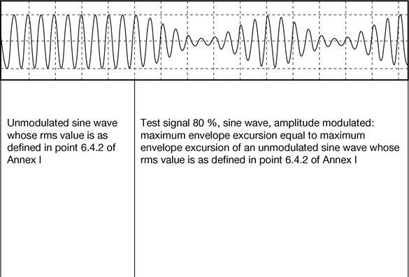
7.4.Characteristics of the test signal to be generatedU.K.
7.4.1.Maximum envelope excursionU.K.
The maximum envelope excursion of the test signal shall equal the maximum envelope excursion of an unmodulated sine wave whose rms value in volts/m is defined in point 6.4.2 of Annex I (see Appendix 3 of this Annex).
7.4.2.Test signal wave formU.K.
The test signal shall be a radio frequency sine wave, amplitude modulated by a 1 kHz sine wave at a modulation depth m of 0,8 ± 0,04.
7.4.3.Modulation depthU.K.
The modulation depth m is defined as:
m
=
(maximum envelope excursion – minimum envelope excursion)/(maximum envelope excursion + minimum envelope excursion).
Appendix 1

Appendix 2

Appendix 3Characteristics of test signal to be generated
ANNEX IXMETHOD OF MEASUREMENT OF RADIATED BROADBAND ELECTROMAGNETIC EMISSIONS FROM ELECTRICAL/ELECTRONIC SUB-ASSEMBLIES
1.GENERALU.K.
1.1.The test method described in this Annex may be applied to ESAs which may be subsequently fitted to vehicles which comply with Annex VI.U.K.
1.2.Measuring apparatusU.K.
The measuring equipment shall comply with the requirements of publication No 16-1 (93) of the International Special Committee on Radio Interference (CISPR).
A quasi-peak detector shall be used for the measurement of broadband electromagnetic emissions in this Annex, or if a peak detector is used an appropriate correction factor shall be used depending on the interference pulse rate.
1.3.Test methodU.K.
This test is intended to measure broadband electromagnetic emissions from ESAs.
2.EXPRESSION OF RESULTSU.K.
The results of measurements shall be expressed in dB microvolts/m (microvolts/m), for 120 kHz band width. If the actual band width B (expressed in kHz) of the measuring apparatus differs from 120 kHz, the readings taken in microvolts/m shall be converted to 120 kHz band width through multiplication by a factor 120/B.
3.MEASURING LOCATIONU.K.
3.1.The test site shall comply with the requirements of CISPR publication No 16-1 (93) (see Appendix 1).U.K.
3.2.The measuring set, test hut or vehicle in which the measurement set is located shall be outside the boundary shown in Appendix 1.U.K.
3.3.Enclosed test facilities may be used if correlation can be shown between the enclosed test facility and an approved outdoor site. Enclosed test facilities do not need to meet the dimensional requirements of Appendix 1 other than the distance from the antenna to the ESA under test and the height of the antenna (see Figures 1 and 2 in Appendix 2).U.K.
3.4.AmbientU.K.
To ensure that there is no extraneous noise or signal of a magnitude sufficient to affect materially the measurement, measurements shall be taken before and after the main test. In both of these measurements, the extraneous noise or signal shall be at least 10 dB below the limits of interference given in point 6.5.2.1 of Annex I, except for intentional narrowband ambient transmissions.
4.ESA STATE DURING TESTSU.K.
4.1.The ESA under test shall be in normal operation mode.U.K.
4.2.Measurements shall not be made while rain or other precipitation is falling on the ESA under test or within 10 minutes after such rain or other precipitation has stopped.U.K.
4.3.Test arrangementsU.K.
4.3.1.The ESA under test and its wiring harnesses shall be supported 50 ± 5 mm above a wooden or equivalent non-conducting table. However, if any part of the ESA under test is intended to be electrically bonded to a vehicle's metal bodywork, that part shall be placed on a ground plane and shall be electrically bonded to the ground plane. The ground plane shall be a metallic sheet with a minimum thickness of 0,5 mm. The minimum size of the ground plane depends on the size of the ESA under test but shall allow for the distribution of the ESA's wiring harness and components. The ground plane shall be connected to the protective conductor of the earthing system. The ground plane shall be situated at a height of 1,0 ± 0,1 m above the test facility floor and shall be parallel to it.U.K.
4.3.2.The ESA under test shall be arranged and connected according to its requirements. The power supply harness shall be positioned along, and within 100 mm of, the edge of the ground plane/table closest to the antenna.U.K.
4.3.3.The ESA under test shall be connected to the grounding system according to the manufacturer's installation specification, no additional grounding connections shall be permitted.U.K.
4.3.4.The minimum distance between the ESA under test and all other conductive structures, such as walls of a shielded area (with the exception of the ground plane/table underneath the test object) must be 1,0 m.U.K.
4.4.Power shall be applied to the ESA under test via a 5 µH/50 Ω artificial network (AN) which shall be electrically bonded to the ground plane. The electrical supply voltage shall be maintained to ±10 % of its nominal system operating voltage. Any ripple voltage shall be less than 1,5 % of the nominal system operating voltage measured at the AN monitoring port.U.K.
4.5.If the ESA under test consists of more than one unit, the interconnecting cables shall ideally be the wiring harness as intended for use in the vehicle. If these are not available, the length between the electronic control unit and the AN shall be 1 500 ± 75 mm.U.K.
All cables in the loom shall be terminated as realistically as possible and preferably with real loads and actuators.
If extraneous equipment is required for the correct operation of the ESA under test, compensation shall be made for the contribution it makes to the emissions measured.
5.ANTENNA TYPE, POSITION AND ORIENTATIONU.K.
5.1.Antenna typeU.K.
Any linearly polarised antenna may be used provided it can be normalised to the reference antenna.
5.2.Height and distance of measurementU.K.
5.2.1.HeightU.K.
The phase centre of the antenna shall be 150 ± 10 mm above ground plane.
5.2.2.Distance of measurementU.K.
The horizontal distance from the phase centre, or tip of the antenna as appropriate, to the edge of the ground plane shall be 1,00 ± 0,05 m. No part of the antenna shall be closer than 0,5 m to the ground plane.
The antenna shall be placed parallel to a plane which is perpendicular to the ground plane and coincident with the edge of the ground plane along which the principal portion of the harness runs.
5.2.3.If the test is carried out in a facility enclosed for radio frequency electromagnetic screening purposes, the antenna's receiving elements shall be no closer than 0,5 m to any radio absorbent material and no closer than 1,5 m to the wall of the enclosed facility. There must be no absorbent material between the receiving antenna and the ESA under test.U.K.
5.3.Antenna orientation and polarisationU.K.
At the measuring point, readings shall be taken both with the antenna in a vertical and in a horizontal polarisation.
5.4.ReadingsU.K.
The maximum of the two readings taken (in accordance with point 5.3) at each spot frequency shall be taken as the characteristic reading at the frequency at which the measurements were made.
6.FREQUENCIESU.K.
6.1.MeasurementsU.K.
Measurements shall be made throughout the 30 to 1 000 MHz frequency range. An ESA is considered as very likely to satisfy the required limits over the whole frequency range if it satisfies them at the following 13 frequencies in the range: 45, 65, 90, 120, 150, 190, 230, 280, 380, 450, 600, 750 and 900 MHzU.K.
In the event that the limit is exceeded during the test, investigations shall be made to ensure that this is due to the ESA and not to background radiation.
6.1.1.The limits apply throughout the frequency range 30 to 1 000 MHz.U.K.
6.1.2.Measurements can be performed with either quasi-peak or peak detectors. The limits given in points 6.2 and 6.5 of Annex I are for quasi-peak. If peak is used, add 38 dB for 1 MHz band width or subtract 22 dB for 1 kHz band width.U.K.
6.2.TolerancesU.K.
| Spot frequency(MHz) | Tolerance(MHz) |
|---|---|
| 45, 65, 90, 120, 150, 190 and 230 | ±5 |
| 280, 380, 450, 600, 750 and 900 | ±20 |
The tolerances apply to frequencies quoted and are intended to avoid interference from transmissions operating on or near the nominal spot frequencies during the time of measurement.
Appendix 1Electrical/electronic sub-assembly test area boundary
Level clear area free from electromagnetic reflecting surfaces
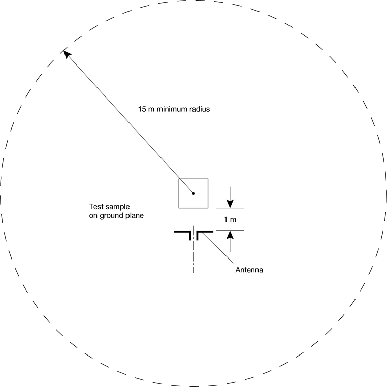
Appendix 2

Figure 2
Radiated electromagnetic emissions from an ESA view of test bench plane of longitudinal symmetry

ANNEX XMETHOD OF MEASUREMENT OF RADIATED NARROWBAND ELECTROMAGNETIC EMISSIONS FROM ELECTRICAL/ELECTRONIC SUB-ASSEMBLIES
1.GENERALU.K.
1.1.The test method described in this Annex may be applied to ESAs.U.K.
1.2.Measuring apparatusU.K.
The measuring equipment shall comply with the requirements of publication No 16-1 (93) of the International Special Committee on Radio Interference (CISPR).
An average detector or a peak detector shall be used for the measurement of radiated narrowband electromagnetic emissions in this Annex.
1.3.Test methodU.K.
1.3.1.This test is intended to measure the narrowband electromagnetic radiation such as might emanate from a microprocessor-based system.U.K.
1.3.2.As a short (2 to 3 minutes) initial step, choosing one antenna polarisation, it is permitted to make sweeps of the frequency range identified in point 6.1 using a spectrum analyser to indicate the existence and/or whereabouts of peak emissions. This may assist in the choice of frequencies to be tested (see point 6).U.K.
2.EXPRESSION OF RESULTSU.K.
The results of measurements shall be expressed in dB microvolts/m (microvolts/m).
3.MEASURING LOCATIONU.K.
3.1.The test site shall comply with the requirements of CISPR publication No 16-1 (93) (see Appendix 1 of Annex IX).U.K.
3.2.The measuring set, test hut or vehicle in which the measurement set is located shall be outside the boundary shown in Appendix 1 of Annex IX.U.K.
3.3.Enclosed test facilities may be used if correlation can be shown between the enclosed test facility and an outdoor site. Enclosed test facilities do not need to meet the dimensional requirements of Appendix 1 of Annex IX other than the distance from the antenna to the ESA under test and the height of the antenna (see Figures 1 and 2 in Appendix 2 of Annex IX).U.K.
3.4.AmbientU.K.
To ensure that there is no extraneous noise or signal of a magnitude sufficient to affect materially the measurement, measurements shall be taken before and after the main test. In both of these measurements, the extraneous noise or signal shall be at least 10 dB below the limits of interference given in point 6.6.2.1 of Annex I, except for intentional narrowband ambient transmissions.
4.ESA STATE DURING TESTSU.K.
4.1.The ESA under test shall be in normal operation mode.U.K.
4.2.Measurements shall not be made while rain or other precipitation is falling on the ESA under test or within 10 minutes after rain or other precipitation has stopped.U.K.
4.3.Test arrangementsU.K.
4.3.1.The ESA under test and its wiring harnesses shall be supported 50 ± 5 mm above a wooden or equivalent non-conducting table. However, if any part of the ESA under test is intended to be electrically bonded to a vehicle's metal bodywork, that part shall be placed on a ground plane and shall be electrically bonded to the ground plane.U.K.
The ground plane shall be a metallic sheet with a minimum thickness of 0,5 mm. The minimum size of the ground plane depends on the size of the ESA under test but shall allow for the distribution of the ESA's wiring harness and components. The ground plane shall be connected to the protective conductor of the earthing system. The ground plane shall be situated at a height of 1,0 ± 0,1 m above the test facility floor and shall be parallel to it.
4.3.2.The ESA under test shall be arranged and connected according to its requirements. The power supply harness shall be positioned along, and within 100 mm of, the edge of the ground plane/table closest to the antenna.U.K.
4.3.3.The ESA under test shall be connected to the grounding system according to the manufacturer's installation specification, no additional grounding connections shall be permitted.U.K.
4.3.4.The minimum distance between the ESA under test and all other conductive structures, such as walls of a shielded area (with the exception of the ground plane/table underneath the test object) must be 1,0 m.U.K.
4.4.Power shall be applied to the ESA under test via a 5 µH/50 Ω resistance artificial network (AN) which shall be electrically bonded to the ground plane. The electrical supply voltage shall be maintained to ±10 % of its nominal system operating voltage. Any ripple voltage shall be less than 1,5 % of the nominal system operating voltage measured at the AN monitoring port.U.K.
4.5.If the ESA under test consists of more than one unit, the interconnecting cables shall ideally be the wiring harness as intended for use in the vehicle. If these are not available, the length between the electronic control unit and the AN shall be 1 500 ± 75 mm. All cables in the loom shall be terminated as realistically as possible and preferably with real loads and actuators. If extraneous equipment is required for the correct operation of the ESA under test, compensation shall be made for the contribution it makes to the emissions measured.U.K.
5.ANTENNA TYPE, POSITION AND ORIENTATIONU.K.
5.1.Antenna typeU.K.
Any linearly polarised antenna may be used provided it can be normalised to the reference antenna.
5.2.Height and distance of measurementU.K.
5.2.1.HeightU.K.
The phase centre of the antenna shall be 150 ± 10 mm above ground plane.
5.2.2.Distance of measurementU.K.
The horizontal distance from the phase centre, or tip of the antenna as appropriate, to the edge of the ground plane shall be 1,00 ± 0,05 m. No part of the antenna shall be closer than 0,5 m to the ground plane.
The antenna shall be placed parallel to a plane which is perpendicular to the ground plane and coincident with the edge of the ground plane along which the principal portion of the harness runs.
5.2.3.If the test is carried out in a facility enclosed for radio frequency electromagnetic screening purposes, the antenna's receiving elements shall be no closer than 0,5 m to any radio absorbent material and no closer than 1,5 m to the wall of the enclosed facility. There must be no absorbent material between the receiving antenna and the ESA under test.U.K.
5.3.Antenna orientation and polarisationU.K.
At the measuring point, readings shall be taken both with the antenna in a vertical and in a horizontal polarisation.
5.4.ReadingsU.K.
The maximum of the two readings taken (in accordance with point 5.3) at each spot frequency shall be taken as the characteristic reading at the frequency at which the measurements were made.
6.FREQUENCIESU.K.
6.1.MeasurementsU.K.
Measurements shall be made throughout the 30 to 1 000 MHz frequency range. This range shall be divided into 13 bands. In each band one spot frequency may be tested to demonstrate that the required limits are satisfied. To confirm that the ESA under test meets the requirements of this Annex, the testing authority shall test one such point in each of the following 13 frequency bands:
30 to 50, 50 to 75, 75 to 100, 100 to 130, 130 to 165, 165 to 200, 200 to 250, 250 to 320, 320 to 400, 400 to 520, 520 to 660, 660 to 820, 820 to 1 000 MHz.
In the event that the limit is exceeded during the test, investigations shall be made to ensure that this is due to the ESA under test and not to background radiation.
6.2.If during the initial step which may have been carried out as described in point 1.3, the radiated narrowband emissions for any of the bands identified in point 6.1 are at least 10 dB below the reference limit, then the ESA shall be deemed to comply with the requirements of this Annex in respect of that frequency band.U.K.
ANNEX XIMETHOD(S) OF TESTING FOR IMMUNITY OF ELECTRICAL/ELECTRONIC SUB-ASSEMBLIES TO ELECTROMAGNETIC RADIATION
1.GENERALU.K.
1.1.The test method(s) described in this Annex may be applied to ESAs.U.K.
1.2.Test methodsU.K.
1.2.1.ESAs may comply with the requirements of any combination of the following test methods at the manufacturer's discretion provided that this results in the full frequency range specified in point 5.1 being covered.U.K.
Stripline testing: see Appendix 1
Bulk current injection testing: see Appendix 2
TEM cell testing: see Appendix 3
Free field test: see Appendix 4
1.2.2.Due to radiation of electromagnetic fields during these tests, all testing shall be conducted in a shielded area (the TEM cell is a shielded area).U.K.
2.EXPRESSION OF RESULTSU.K.
For the tests described in this Annex, field strengths shall be expressed in volts/m and injected current shall be expressed in milliamps.
3.MEASURING LOCATIONU.K.
3.1.The test facility shall be capable of generating the required test signal over the frequency ranges defined in this Annex. The test facility shall comply with (national) legal requirements regarding the emission of electromagnetic signals.U.K.
3.2.The measuring equipment shall be located outside the chamber.U.K.
4.STATE OF ESA DURING TESTSU.K.
4.1.The ESA under test shall be in normal operation mode. It shall be arranged as defined in this Annex unless individual test methods dictate otherwise.U.K.
4.2.Power shall be applied to the ESA under test via an (5 µ H/50 Ω) artificial network (AN), which shall be electrically grounded. The electrical supply voltage shall be maintained to ±10 % of its nominal system operating voltage. Any ripple voltage shall be less than 1,5 % of the nominal system operating voltage measured at the AN monitoring port.U.K.
4.3.Any extraneous equipment required to operate the ESA under test shall be in place during the calibration phase. No extraneous equipment shall be closer than 1 m from the reference point during calibration.U.K.
4.4.To ensure reproducible measurement results are obtained when tests and measurements are repeated, the test signal generating equipment and its layout shall be to the same specification as that used during each appropriate calibration phase (points 7.2, 7.3.2.3, 8.4, 9.2 and 10.2).U.K.
4.5.If the ESA under test consists of more than one unit, the interconnecting cables shall ideally be the wiring harness as intended for use in the vehicle. If these are not available, the length between the electronic control unit and the AN shall be 1 500 ± 75 mm. All cables in the loom shall be terminated as realistically as possible and preferably with real loads and actuators.U.K.
5.FREQUENCY RANGE, DWELL TIMESU.K.
5.1.Measurements shall be made in the 20 to 1 000 MHz frequency range.U.K.
5.2.To confirm that the ESA(s) meet(s) the requirements of this Annex, the tests shall be performed at up to 14 spot frequencies in the range, for example:U.K.
27, 45, 65, 90, 120, 150, 190, 230, 280, 380, 450, 600, 750 and 900 MHz
The response time of the equipment under test shall be considered and the dwell time shall be sufficient to allow the equipment under test to react under normal conditions. In any case, it shall not be less than two seconds.
6.CHARACTERISTICS OF TEST SIGNAL TO BE GENERATEDU.K.
6.1.Maximum envelope excursionU.K.
The maximum envelope excursion of the test signal shall equal the maximum envelope excursion of an unmodulated sine wave whose rms value is defined in point 6.4.2 of Annex I (see Appendix 3 of Annex VIII).
6.2.Test signal wave formU.K.
The test signal shall be a radio frequency sine wave, amplitude modulated by a 1 kHz sine wave at a modulation depth m of 0,8 ± 0,04.
6.3.Modulation depthU.K.
The modulation depth m is defined as:
m
=
(maximum envelope excursion — minimum envelope excursion)/(maximum envelope excursion + minimum envelope excursion)
7.STRIPLINE TESTINGU.K.
7.1.Test methodU.K.
This test method consists of subjecting the wiring harness connecting the components in an ESA to specified field strengths.
7.2.Field strength measurement in the striplineU.K.
At each desired test frequency a level of power shall be fed into the stripline to produce the required field strength in the test area with the ESA under test absent, this level of forward power, or another parameter directly related to the forward power required to define the field, shall be measured and the results recorded. These results shall be used for type-approval tests unless changes occur in the facilities or equipment which necessitate this procedure being repeated. During this process, the position of the field probe head shall be under the active conductor, centred in longitudinal, vertical and transversal directions. The housing of the probe's electronics shall be as far away from the longitudinal stripline axis as possible.
7.3.Installation of the ESA under testU.K.
7.3.1.150 mm stripline testingU.K.
The test method allows the generation of homogeneous fields between an active conductor (the stripline 50 Ω impedance), and a ground plane (the conducting surface of the mounting table), between which part of the wiring harness may be inserted. The electronic controller(s) of the ESA under test shall be installed on the ground plane but outside the stripline with one of its edges parallel to the active conductor of the stripline. It shall be 200 ± 10 mm from a line on the ground plane directly under the edge of the active conductor.U.K.
The distance between any edge of the active conductor and any peripheral device used for measurement shall be at least 200 mm.
The wiring harness section of the ESA under test shall be placed in a horizontal attitude between the active conductor and the ground plane (see Figures 1 and 2 in Appendix 1).
7.3.1.1.The minimum length of the wiring harness, which shall include the power harness to the electronic control unit and shall be placed under the stripline, shall be 1,5 m unless the wiring harness in the vehicle is less than 1,5 m. In this case, the length of the wiring harness shall be that of the longest length of harness used in the vehicle installation. Any line branches occurring in this length shall be routed perpendicularly to the longitudinal axis of the line.U.K.
7.3.1.2.Alternatively, the fully extended length of the wiring harness, including the length of the longest of any branches, shall be 1,5 m.U.K.
7.3.2.800 mm stripline testingU.K.
7.3.2.1.Test methodU.K.
The stripline consists of two parallel metallic plates separated by 800 mm. Equipment under test is positioned centrally between the plates and subjected to an electromagnetic field (see Figures 3 and 4 in Appendix 1).
This method can test complete electronic systems including sensors and actuators as well as the controller and wiring loom. It is suitable for apparatus whose largest dimension is less than one-third of the plate separation.
7.3.2.2.Positioning of striplineU.K.
The stripline shall be housed in a screened room (to prevent external emissions) and positioned 2 m away from walls and any metallic enclosure to prevent electromagnetic reflections. RF absorber material may be used to damp these reflections. The stripline shall be placed on non-conducting supports at least 0,4 m above the floor.
7.3.2.3.Calibration of the striplineU.K.
A field measuring probe shall be positioned within the central one-third of the longitudinal, vertical and transverse dimensions of the space between the parallel plates with the system under test absent. The associated measuring equipment shall be sited outside the screen room.
At each desired test frequency, a level of power shall be fed into the stripline to produce the required field strength at the antenna. This level of forward power, or another parameter directly related to the forward power required to define the field, shall be used for type-approval tests unless changes occur in the facilities or equipment which necessitate this procedure being repeated.
7.3.2.4.Installation of the ESA under testU.K.
The main control unit shall be positioned within the central one-third of the longitudinal, vertical and transverse dimensions of the space between the parallel plates. It shall be supported on a stand made from non-conducting material.
7.3.2.5.Main wiring loom and sensor/actuator cablesU.K.
The main wiring loom and any sensor/actuator cables shall rise vertically from the control unit to the top ground plate (this helps to maximise coupling with the electromagnetic field). Then they shall follow the underside of the plate to one of its free edges where they shall loop over and follow the top of the ground plate as far as the connections to the stripline feed. The cables shall then be routed to the associated equipment which shall be sited in an area outside the influence of the electromagnetic field, for example: on the floor of the screened room 1 m longitudinally away from the stripline.
8.FREE FIELD ESA IMMUNITY TESTU.K.
8.1.Test methodU.K.
This test method allows the testing of vehicle electrical/electronic systems by exposing an ESA to electromagnetic radiation generated by an antenna.
8.2.Test bench descriptionU.K.
The test shall be performed inside a semi-anechoic chamber on a bench top.U.K.
8.2.1.Ground planeU.K.
8.2.1.1.For free field immunity testing, the ESA under test and its wiring harnesses shall be supported 50 ± 5 mm above a wooden or equivalent non-conducting table. However, if any part of the ESA under test is intended to be electrically bonded to a vehicle's metal bodywork, that part shall be placed on a ground plane and shall be electrically bonded to the ground plane. The ground plane shall be a metallic sheet with a minimum thickness of 0,5 mm. The minimum size of the ground plane depends on the size of the ESA under test but shall allow for the distribution of the ESA's wiring harness and components. The ground plane shall be connected to the protective conductor of the earthing system. The ground plane shall be situated at a height of 1,0 ± 0,1 m above the test facility floor and shall be parallel to it.U.K.
8.2.1.2.The ESA under test shall be arranged and connected according to its requirements. The power supply harness shall be positioned along, and within 100 mm of, the edge of the ground plane/table closest to the antenna.U.K.
8.2.1.3.The ESA under test shall be connected to the grounding system according to the manufacturer's installation specification, no additional grounding connections shall be permitted.U.K.
8.2.1.4.The minimum distance between the ESA under test and all other conductive structures, such as walls of a shielded area (with the exception of the ground plane/table underneath the test object) must be 1,0 m.U.K.
8.2.1.5.The dimension of any ground plane shall be 2,25 square metres or larger in area with the smaller side no less than 750 mm. The ground plane shall be bonded to the chamber with bonding straps such that the DC bonding resistance shall not exceed 2,5 milliohms.U.K.
8.2.2.Installation of ESA under testU.K.
For large equipment mounted on a metal test stand, the test stand shall be considered a part of the ground plane for testing purposes and shall be bonded accordingly. The faces of the test sample shall be located at a minimum of 200 mm from the edge of the ground plane. All leads and cables shall be a minimum of 100 mm from the edge of the ground plane and the distance to the ground plane (from the lowest point of the harness) shall be 50 ± 5 mm above the ground plane. Power shall be applied to the ESA under test via an (5 µ H/50 Ω) artificial network (AN).
8.3.Field generating device type, position and orientationU.K.
8.3.1.Field generating device typeU.K.
8.3.1.1.The field generating device type(s) shall be chosen such that the desired field strength is achieved at the reference point (see point 8.3.4) at the appropriate frequencies.U.K.
8.3.1.2.The field generating device(s) may be (an) antenna(s) or a plate antenna.U.K.
8.3.1.3.The construction and orientation of any field generating device shall be such that the generated field is polarised: from 20 to 1 000 MHz horizontally or vertically.U.K.
8.3.2.Height and distance of measurementU.K.
8.3.2.1.HeightU.K.
The phase centre of any antenna shall be 150 ± 10 mm above the ground plane on which the ESA under test rests. No parts of any antenna's radiating elements shall be closer than 250 mm to the floor of the facility.
8.3.2.2.Distance of measurementU.K.
8.3.2.2.1.In-service conditions may best be approximated by placing the field generating device as far from the ESA as practical. This distance will typically lie within the range 1 to 5 m.U.K.
8.3.2.2.2.If the test is carried out in an enclosed facility, the field generating device's radiating elements shall be no closer than 0,5 m to any radio absorbent material and no closer than 1,5 m to the wall of the facility. There shall be no absorbent material interposed between the transmitting antenna and the ESA under test.U.K.
8.3.3.Antenna location relative to ESA under testU.K.
8.3.3.1.The field generating device's radiating elements shall not be closer than 0,5 m to the edge of the ground plane.U.K.
8.3.3.2.The phase centre of the field generating device shall be on a plane which:U.K.
(a)
is perpendicular to the ground plane;
(b)
bisects the edge of the ground plane and the midpoint of the principal portion of the wiring harness; and
(c)
is perpendicular to the edge of the ground plane and the principal portion of the wiring harness.
The field generating device shall be placed parallel to this plane (see Figures 1 and 2 in Appendix 4).
8.3.3.3.Any field generating device which is placed over the ground plane or ESA under test shall extend over the ESA under test.U.K.
8.3.4.Reference pointU.K.
For the purpose of this Annex the reference point is the point at which the field strength shall be established and shall be defined as follows:U.K.
8.3.4.1.at least 1 m horizontally from the antenna phase centre or at least 1 m vertically from the radiating elements of a plate antenna;U.K.
8.3.4.2.on a plane which:U.K.
(a)
is perpendicular to the ground plane;
(b)
is perpendicular to the edge of the ground plane along which the principal portion of the wiring harness runs;
(c)
bisects the edge of the ground plane and the midpoint of the principal portion of the wiring harness; and
(d)
is coincident with the midpoint of the principal portion of the harness which runs along the edge of the ground plane closest to the antenna;
8.3.4.3.150 ± 10 mm above the ground plane.U.K.
8.4.Generation of required field strength: test methodologyU.K.
8.4.1.The ‘substitution method’ shall be used to establish the test field conditions.U.K.
8.4.2.Substitution methodU.K.
At each desired test frequency, a level of power shall be fed into the field generating device to produce the required field strength at the reference point (as defined in point 8.3.4 in the test area with the ESA under test absent), this level of forward power, or another parameter directly related to the forward power required to define the field, shall be measured and the results recorded. These results shall be used for type-approval tests unless changes occur in the facilities or equipment which necessitates this procedure being repeated.
8.4.3.Extraneous equipment must be a minimum of 1 m from the reference point during calibration.U.K.
8.4.4.Field strength measuring deviceU.K.
A suitable compact field strength measuring device shall be used to determine the field strength during the calibration phase of the substitution method.
8.4.5.The phase centre of the field strength measuring device shall be positioned at the reference point.U.K.
8.4.6.The ESA under test which may include an additional ground plane shall then be introduced into the test facility and positioned in accordance with the requirements of point 8.3. If a second ground plane is used, then it shall be within 5 mm of the bench ground plane and electrically bounded to it. The required forward power defined in point 8.4.2 at each frequency as defined in point 5 shall then be applied to the field generating device.U.K.
8.4.7.Whatever parameter was chosen in point 8.4.2 to define the field, the same parameter shall be used to determine the field strength during the test.U.K.
8.5.Field strength contourU.K.
8.5.1.During the calibration phase of the substitution method (prior to an ESA under test being introduced into the test area), the field strength shall not be less than 50 % of the nominal field strength 0,5 ± 0,05 m either side of the reference point on a line parallel to the edge of the ground plane nearest to the antenna and passing through the reference point.U.K.
9.TEM CELL TESTINGU.K.
9.1.Test methodU.K.
The transverse electromagnetic mode (TEM) cell generates homogeneous fields between the internal conductor (septum) and housing (ground plane). It is used for testing ESAs (see Figure 1 in Appendix 3).
9.2.Field strength measurement in a TEM cellU.K.
9.2.1.The electric field in the TEM cell shall be determined by using the equation:U.K.
|E| = (√(P × Z))/d
E
=
Electric field (volts/metre)
P
=
Power flowing into cell (W)
Z
=
Impedance of cell (50 Ω)
d
=
Separation distance (metres) between the upper wall and the plate (septum).
9.2.2.Alternatively an appropriate field strength sensor shall be placed in the upper half of the TEM cell. In this part of the TEM cell the electronic control unit(s) has only a small influence on the test field. The output of this sensor shall determine the field strength.U.K.
9.3.Dimensions of TEM cellU.K.
In order to maintain a homogeneous field in the TEM cell and to obtain repeatable measurement results, the test object shall not be larger than one-third of the cell inside height.
Recommended TEM cell dimensions are given in Appendix 3, Figures 2 and 3.
9.4.Power, signal and control wiresU.K.
The TEM cell shall be attached to a co-axial socket panel and connected as closely as possible to a plug connector with an adequate number of pins. The supply and signal leads from the plug connector in the cell wall shall be directly connected to the test object.
The external components such as sensors, power supply and control elements can be connected:
(a)
to a screened peripheral;
(b)
to a vehicle next to the TEM cell; or
(c)
directly to the screened patchboard.
Screened cables must be used in connecting the TEM cell to the peripheral or the vehicle if the vehicle or peripheral is not in the same or adjacent screened room.
10.BULK CURRENT INJECTION TESTINGU.K.
10.1.Test methodU.K.
This is a method of carrying out immunity tests by inducing currents directly into a wiring harness using a current injection probe. The injection probe consists of a coupling clamp through which the cables of the ESA under test are passed. Immunity tests can then be carried out by varying the frequency of the induced signals.
The ESA under test may be installed on a ground plane as in point 8.2.1 or in a vehicle in accordance with the vehicle design specification.
10.2.Calibration of bulk current injection probe prior to commencing testsU.K.
The injection probe shall be mounted in a calibration jig. Whilst sweeping the test frequency range, the power required to achieve the current specified in point 6.7.2.1 of Annex I shall be monitored. This method calibrates the bulk current injection system forward power versus current prior to testing, and it is this forward power which shall be applied to the injection probe when connected to the ESA under test via the cables used during calibration. It should be noted that the monitored power applied to the injection probe is the forward power.
10.3.Installation of the ESA under testU.K.
For an ESA mounted on a ground plane as in point 8.2.1 all cables in the wiring harness shall be terminated as realistically as possible and preferably with real loads and actuators. For both vehicle mounted and ground plane mounted ESAs the current injection probe shall be mounted in turn around all the wires in the wiring harness to each connector and 150 ± 10mm from each connector of the ESA under test electronic control units (ECU), instrument modules or active sensors as illustrated in Appendix 2.
10.4.Power, signal and control wiresU.K.
For an ESA under test mounted on a ground plane as in point 8.2.1, a wiring harness shall be connected between an artificial network (AN) and the principal electronic control unit (ECU). This harness shall run parallel to the edge of the ground plane and 200 mm minimum from its edge. This harness shall contain the power feed wire which is used to connect the vehicle battery to this ECU and the power return wire if used on the vehicle.
The distance from the ECU to the AN shall be 1,0 ± 0,1 m or shall be the harness length between the ECU and the battery as used on the vehicle, if known, whichever is the shorter. If a vehicle harness is used then any line branches which occur in this length shall be routed along the ground plane but perpendicular away from the edge of the ground plane. Otherwise the ESA under test wires which are in this length shall break out at the AN.
Appendix 1


1
=
Ground plate
2
=
Main loom and sensor/actuator cables
3
=
Wooden frame
4
=
Driven plate
5
=
Insulator
6
=
Test object

Appendix 2Example of BCI test configuration

1
=
DUT
2
=
RF measuring probe (optional)
3
=
RF injection probe
4
=
Artificial network
5
=
Shielded room filter network
6
=
Power source
7
=
DUT interface: stimulation and monitoring equipment
8
=
Signal generator
9
=
Broadband amplifier
10
=
RF 50 Ω directional complex
11
=
RF power level measuring device or equivalent
12
=
Spectrum analyser or equivalent (optional)
Appendix 3

1
=
Outer conductor, shield
2
=
Inner conductor (septum)
3
=
Insulator
4
=
Input
5
=
Insulator
6
=
Door
7
=
Socket panel
8
=
Test object power supply
9
=
Terminating resistance 50 Ω
10
=
Insulation
11
=
Test object (maximum height one third of distance between cell floor and septum)

Figure 3U.K.
The following table shows the dimensions for constructing a cell with specified upper frequency limits:
| Upper frequency(MHz) | Cell form factorW: b | Cell form factorL/W | Plate separationb (cm) | SeptumS (cm) |
|---|---|---|---|---|
| 200 | 1,69 | 0,66 | 56 | 70 |
| 200 | 1,00 | 1,00 | 60 | 50 |
Typical TEM cell dimensions
Appendix 4


ANNEX XII
PART AU.K.Repealed Directive with list of its successive amendments(referred to in Article 6)
| Council Directive 75/322/EEC | |
| Council Directive 82/890/EEC | only as regards the reference to Directive 75/322/EEC in Article 1(1) |
| Directive 97/54/EC of the European Parliament and of the Council | only as regards the reference to Directive 75/322/EEC in the first indent of Article 1 |
| Commission Directive 2000/2/EC | Article 1 and Annex only |
| Commission Directive 2001/3/EC | Article 2 and Annex II only |
| Point I.A.13 of Annex II to the 2003 Act of Accession | |
| Council Directive 2006/96/EC | only as regards the reference to Directive 75/322/EEC in Article 1 and Annex, point A.12. |
PART BU.K.List of time-limits for transposition into national law and application(referred to in Article 6)
| a In conformity with Article 2 of Directive 2000/2/EC: 1.With effect from 1 January 2001, Member States may not, on grounds relating to electromagnetic compatibility:
if the vehicles, components or separate technical units comply with the requirements of Directive 75/322/EEC, as amended by this Directive. 2.With effect from 1 October 2002, Member States:
for any type of vehicle component or separate technical unit, if the requirements of Directive 75/322/EEC, as amended by this Directive, are not fulfilled. 3.Paragraph 2 shall not apply to vehicle types approved before 1 October 2002 pursuant to Council Directive 77/537/EEC“b nor to any subsequent extensions to these approvals. 4.With effect from 1 October 2008, Member States:
if the requirements of this Directive are not fulfilled. 5.Without prejudice to paragraphs 2 and 4, in the case of replacement parts, Member States shall continue to grant EC type-approval and to permit the sale and entry into service of components or separate technical units intended for use on vehicle types which have been approved before 1 October 2002 pursuant to Directive 75/322/EEC or Directive 77/537/EEC and, where applicable, subsequent extensions to these approvals.”. | ||
| Directive | Time-limit for transposition | Date of application |
|---|---|---|
| 75/322/EEC | 21 November 1976 | — |
| 82/890/EEC | 21 June 1984 | — |
| 97/54/EC | 22 September 1998 | 23 September 1998 |
| 2000/2/EC | 31 December 2000a | — |
| 2001/3/EC | 30 June 2002 | — |
| 2006/96/EC | 31 December 2006 | — |
ANNEX XIIICORRELATION TABLE
| Directive 75/322/EEC | Directive 2000/2/EC | This Directive |
|---|---|---|
| Article 1 | Article 1 | |
| Article 2 | Article 2 | |
| Article 4 | Article 3 | |
| Article 5 | Article 4 | |
| Article 6(1) | — | |
| Article 6(2) | Article 5 | |
| — | Article 6 | |
| — | Article 7 | |
| Article 7 | Article 8 | |
| Annex I | Annex I | |
| Annex IIA | Annex II | |
| Annex IIB | Annex III | |
| Annex IIIA | Annex IV | |
| Annex IIIB | Annex V | |
| Annex IV | Annex VI | |
| Annex V | Annex VII | |
| Annex VI | Annex VIII | |
| Annex VII | Annex IX | |
| Annex VIII | Annex X | |
| Annex IX | Annex XI | |
| — | Annex XII | |
| — | Annex XIII |
(2)
Opinion of the European Parliament of 19 February 2008 (not yet published in the Official Journal) and Council Decision of 22 June 2009.
(4)
See Annex XII, Part A.
(8)
If applicable.
(9)
For example: radio telephone and citizens' band radio.
(10)
Delete as appropriate.
(11)
Indicate tolerance.
(12)
Delete where not applicable.
(13)
Delete where not applicable.
(14)
If the means of identification of type contains characters not relevant to describe the vehicle, component or separate technical unit types covered by this type-approval certificate such characters shall be represented in the documentation by the symbol: ‘?’ (for example ABC??123??).
(15)
Delete where not applicable.
(16)
If the means of identification of type contains characters not relevant to describe the vehicle, component or separate technical unit types covered by this type-approval certificate such characters shall be represented in the documentation by the symbol: ‘?’ (for example ABC??123??).
Options/Cymorth
Print Options
PrintThe Whole Directive
You have chosen to open the Whole Directive
The Whole Directive you have selected contains over 200 provisions and might take some time to download. You may also experience some issues with your browser, such as an alert box that a script is taking a long time to run.
Would you like to continue?
You have chosen to open Schedules only
Y Rhestrau you have selected contains over 200 provisions and might take some time to download. You may also experience some issues with your browser, such as an alert box that a script is taking a long time to run.
Would you like to continue?
Mae deddfwriaeth ar gael mewn fersiynau gwahanol:
Y Diweddaraf sydd Ar Gael (diwygiedig):Y fersiwn ddiweddaraf sydd ar gael o’r ddeddfwriaeth yn cynnwys newidiadau a wnaed gan ddeddfwriaeth ddilynol ac wedi eu gweithredu gan ein tîm golygyddol. Gellir gweld y newidiadau nad ydym wedi eu gweithredu i’r testun eto yn yr ardal ‘Newidiadau i Ddeddfwriaeth’.
Gwreiddiol (Fel y’i mabwysiadwyd gan yr UE): Mae'r wreiddiol version of the legislation as it stood when it was first adopted in the EU. No changes have been applied to the text.
Pwynt Penodol mewn Amser: This becomes available after navigating to view revised legislation as it stood at a certain point in time via Advanced Features > Show Timeline of Changes or via a point in time advanced search.
Gweler y wybodaeth ychwanegol ochr yn ochr â’r cynnwys
Rhychwant ddaearyddol: Indicates the geographical area that this provision applies to. For further information see ‘Frequently Asked Questions’.
Dangos Llinell Amser Newidiadau: See how this legislation has or could change over time. Turning this feature on will show extra navigation options to go to these specific points in time. Return to the latest available version by using the controls above in the What Version box.
Dewisiadau Agor
Dewisiadau gwahanol i agor deddfwriaeth er mwyn gweld rhagor o gynnwys ar y sgrin ar yr un pryd
Rhagor o Adnoddau
Gallwch wneud defnydd o ddogfennau atodol hanfodol a gwybodaeth ar gyfer yr eitem ddeddfwriaeth o’r tab hwn. Yn ddibynnol ar yr eitem ddeddfwriaeth sydd i’w gweld, gallai hyn gynnwys:
- y PDF print gwreiddiol y fel adopted version that was used for the EU Official Journal
- rhestr o newidiadau a wnaed gan a/neu yn effeithio ar yr eitem hon o ddeddfwriaeth
- pob fformat o’r holl ddogfennau cysylltiedig
- slipiau cywiro
- dolenni i ddeddfwriaeth gysylltiedig ac adnoddau gwybodaeth eraill
Llinell Amser Newidiadau
Mae’r llinell amser yma yn dangos y fersiynau gwahanol a gymerwyd o EUR-Lex yn ogystal ag unrhyw fersiynau dilynol a grëwyd ar ôl y diwrnod ymadael o ganlyniad i newidiadau a wnaed gan ddeddfwriaeth y Deyrnas Unedig.
Cymerir dyddiadau fersiynau’r UE o ddyddiadau’r dogfennau ar EUR-Lex ac efallai na fyddant yn cyfateb â’r adeg pan ddaeth y newidiadau i rym ar gyfer y ddogfen.
Ar gyfer unrhyw fersiynau a grëwyd ar ôl y diwrnod ymadael o ganlyniad i newidiadau a wnaed gan ddeddfwriaeth y Deyrnas Unedig, bydd y dyddiad yn cyd-fynd â’r dyddiad cynharaf y daeth y newid (e.e. ychwanegiad, diddymiad neu gyfnewidiad) a weithredwyd i rym. Am ragor o wybodaeth gweler ein canllaw i ddeddfwriaeth ddiwygiedig ar Ddeall Deddfwriaeth.
Rhagor o Adnoddau
Defnyddiwch y ddewislen hon i agor dogfennau hanfodol sy’n cyd-fynd â’r ddeddfwriaeth a gwybodaeth am yr eitem hon o ddeddfwriaeth. Gan ddibynnu ar yr eitem o ddeddfwriaeth sy’n cael ei gweld gall hyn gynnwys:
- y PDF print gwreiddiol y fel adopted fersiwn a ddefnyddiwyd am y copi print
- slipiau cywiro
liciwch ‘Gweld Mwy’ neu ddewis ‘Rhagor o Adnoddau’ am wybodaeth ychwanegol gan gynnwys
- rhestr o newidiadau a wnaed gan a/neu yn effeithio ar yr eitem hon o ddeddfwriaeth
- manylion rhoi grym a newid cyffredinol
- pob fformat o’r holl ddogfennau cysylltiedig
- dolenni i ddeddfwriaeth gysylltiedig ac adnoddau gwybodaeth eraill
 Mae’r holl gynnwys ar gael dan Drwydded Llywodraeth Agored v3.0 ac eithrio ble nodir yn wahanol. Yn ychwanegol mae’r safle hwn â chynnwys sy’n deillio o EUR-Lex, a ailddefnyddiwyd dan delerau Penderfyniad y Comisiwn 2011/833/EU ar ailddefnyddio dogfennau o sefydliadau’r UE. Am ragor o wybodaeth gweler ddatganiad cyhoeddus Swyddfa Gyhoeddiadau’r UE ar ailddefnyddio.