- Y Diweddaraf sydd Ar Gael (Diwygiedig)
- Pwynt Penodol mewn Amser (01/07/2013)
- Gwreiddiol (Fel y’i mabwysiadwyd gan yr UE)
Commission Regulation (EU) No 582/2011Dangos y teitl llawn
Commission Regulation (EU) No 582/2011 of 25 May 2011 implementing and amending Regulation (EC) No 595/2009 of the European Parliament and of the Council with respect to emissions from heavy duty vehicles (Euro VI) and amending Annexes I and III to Directive 2007/46/EC of the European Parliament and of the Council (Text with EEA relevance)
You are here:
- Rheoliadau yn deillio o’r UE
- 2011 No. 582
- Annexes only

Pa Fersiwn
Nodweddion Uwch
- Dangos Graddfa Ddaearyddol(e.e. Lloegr, Cymru, Yr Alban aca Gogledd Iwerddon)
- Dangos Llinell Amser Newidiadau
Rhagor o Adnoddau
PDF o Fersiynau Diwygiedig
- ddiwygiedig 01/09/20202.26 MB
- ddiwygiedig 15/12/20192.14 MB
- ddiwygiedig 22/07/20181.82 MB
- ddiwygiedig 18/01/20181.82 MB
- ddiwygiedig 27/07/20171.81 MB
- ddiwygiedig 01/01/20171.81 MB
- ddiwygiedig 17/10/20161.79 MB
- ddiwygiedig 03/07/20141.83 MB
- ddiwygiedig 05/03/20141.84 MB
- ddiwygiedig 01/07/20133.92 MB
- ddiwygiedig 03/02/20123.91 MB
Deddfwriaeth yn deillio o’r UE
Pan adawodd y DU yr UE, cyhoeddodd legislation.gov.uk ddeddfwriaeth yr UE a gyhoeddwyd gan yr UE hyd at ddiwrnod cwblhau’r cyfnod gweithredu (31 Rhagfyr 2020 11.00 p.m.). Ar legislation.gov.uk, mae'r eitemau hyn o ddeddfwriaeth yn cael eu diweddaru'n gyson ag unrhyw ddiwygiadau a wnaed gan y DU ers hynny.


Mae'r eitem hon o ddeddfwriaeth yn tarddu o'r UE
Mae legislation.gov.uk yn cyhoeddi fersiwn y DU. Mae EUR-Lex yn cyhoeddi fersiwn yr UE. Mae Archif Gwe Ymadael â’r UE yn rhoi cipolwg ar fersiwn EUR-Lex o ddiwrnod cwblhau’r cyfnod gweithredu (31 Rhagfyr 2020 11.00 p.m.).
Changes over time for: Commission Regulation (EU) No 582/2011 (Annexes only)
Version Superseded: 05/03/2014
Alternative versions:
- 25/05/2011- Amendment
- 03/02/2012- Amendment
- 01/07/2013- Amendment
- 01/07/2013
Point in time - 05/03/2014- Amendment
- 03/07/2014- Amendment
- 17/10/2016- Amendment
- 01/01/2017- Amendment
- 27/07/2017- Amendment
- 22/07/2018- Amendment
- 15/12/2019- Amendment
- Exit day: start of implementation period31/01/2020 11pm- Amendment
- End of implementation period31/12/2020- Amendment
Status:
Point in time view as at 01/07/2013.
Changes to legislation:
There are currently no known outstanding effects by UK legislation for Commission Regulation (EU) No 582/2011.
Changes to Legislation
Revised legislation carried on this site may not be fully up to date. At the current time any known changes or effects made by subsequent legislation have been applied to the text of the legislation you are viewing by the editorial team. Please see ‘Frequently Asked Questions’ for details regarding the timescales for which new effects are identified and recorded on this site.
ANNEX IU.K. ADMINISTRATIVE PROVISIONS FOR EC TYPE-APPROVAL
1.REQUIREMENTS ON FUEL RANGEU.K.
1.1. Requirements on universal fuel range type-approval U.K.
A universal fuel range approval shall be granted subject to the requirements specified in points 1.1.1 to 1.1.6.1.
1.1.1.The parent engine shall meet the requirements of this Regulation on the appropriate reference fuels specified in Annex IX. Specific requirements shall apply to natural gas fuelled engines, as laid down in point 1.1.3.U.K.
1.1.2.If the manufacturer permits to operate the engine family to run on market fuels not included in Directive 98/70/EC of the European Parliament and of the Council(1) and the EN 228 CEN standards in the case of unleaded petrol and EN 590 CEN standard in the case of diesel, such as running on B100, the manufacturer shall, in addition to the requirements in point 1.1.1:U.K.
(a)
declare the fuels the engine family is capable to run on in point 3.2.2.2.1 of Part 1 of Appendix 4;
(b)
demonstrate the capability of the parent engine to meet the requirements of this Regulation on the fuels declared;
(c)
be liable to meet the requirements of in-service conformity specified in Annex II on the fuels declared including any blend between the declared fuels and the market fuels included in Directive 98/70/EC and the relevant CEN standards.
1.1.3.In the case of a natural gas fuelled engine the manufacturer shall demonstrate the parent engines capability to adapt to any fuel composition that may occur on the market within the European Union.U.K.
In the case of natural gas there are generally two types of fuel, high calorific fuel (H-gas) and low calorific fuel (L-gas), but with a significant spread within both ranges; they differ significantly in their energy content expressed by the Wobbe Index and in their λ-shift factor (Sλ). Natural gases with a λ-shift factor between 0,89 and 1,08 (0,89 ≤ Sλ ≤ 1,08) are considered to belong to H-range, while natural gases with a λ-shift factor between 1,08 and 1,19 (1,08 ≤ Sλ ≤ 1,19) are considered to belong to L-range. The composition of the reference fuels reflects the extreme variations of Sλ.
The parent engine shall meet the requirements of this Regulation on the reference fuels GR (fuel 1) and G25 (fuel 2), as specified in Annex IX, without any readjustment to the fuelling between the two tests. One adaptation run over one WHTC hot cycle without measurement is permitted after the change of the fuel. After the adaptation run the engine shall be cooled down in accordance with Section 7.6.1 of Annex 4B to UN/ECE Regulation No 49.
1.1.3.1.At the manufacturer's request the engine may be tested on a third fuel (fuel 3) if the λ-shift factor (Sλ) lies between 0,89 (that is the lower range of GR) and 1,19 (that is the upper range of G25), for example when fuel 3 is a market fuel. The results of this test may be used as a basis for the evaluation of the conformity of the production.U.K.
1.1.4.In the case of an engine fuelled with natural gas which is self adaptive for the range of H-gases on the one hand and the range of L-gases on the other hand, and which switches between the H-range and the L-range by means of a switch, the parent engine shall be tested on the relevant reference fuel as specified in Annex IX for each range, at each position of the switch. The fuels are GR (fuel 1) and G23 (fuel 3) for the H-range of gases and G25 (fuel 2) and G23 (fuel 3) for the L-range of gases. The parent engine shall meet the requirements of this Regulation at both positions of the switch without any readjustment to the fuelling between the two tests at each position of the switch. One adaptation run over one WHTC hot cycle without measurement is permitted after the change of the fuel. After the adaptation run the engine shall be cooled down in accordance with Section 7.6.1 of Annex 4B to UN/ECE Regulation No 49.U.K.
1.1.4.1.At the manufacturer's request the engine may be tested on a third fuel instead of G23 (fuel 3) if the λ-shift factor (Sλ) lies between 0,89 (that is the lower range of GR) and 1,19 (that is the upper range of G25), for example when fuel 3 is a market fuel. The results of this test may be used as a basis for the evaluation of the conformity of the production.U.K.
1.1.5.In the case of natural gas engines, the ratio of the emission results ‘r’ shall be determined for each pollutant as follows:U.K.

, or
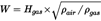
, and

1.1.6.In the case of LPG the manufacturer shall demonstrate the parent engines capability to adapt to any fuel composition that may occur across the market.U.K.
In the case of LPG there are variations in C3/C4 composition. These variations are reflected in the reference fuels. The parent engine shall meet the emission requirements on the reference fuels A and B as specified in Annex IX without any readjustment to the fuelling between the two tests. One adaptation run over one WHTC hot cycle without measurement is permitted after the change of the fuel. After the adaptation run the engine shall be cooled down in accordance with Section 7.6.1 of Annex 4B to UN/ECE Regulation No 49.
1.1.6.1.The ratio of emission results ‘r’ shall be determined for each pollutant as follows:U.K.

[F11.2. Requirements on restricted fuel range type-approval in case of positive-ignition engines fuelled with natural gas or LPG U.K.
Fuel range restricted approval shall be granted subject to the requirements specified in points 1.2.1 to 1.2.2.2.]
1.2.1.Exhaust emissions type-approval of an engine running on natural gas and laid out for operation on either the range of H-gases or on the range of L-gases.U.K.
The parent engine shall be tested on the relevant reference fuel, as specified in Annex IX, for the relevant range. The fuels are GR (fuel 1) and G23 (fuel 3) for the H-range of gases and G25 (fuel 2) and G23 (fuel 3) for the L-range of gases. The parent engine shall meet the requirements of this Regulation without any readjustment to the fuelling between the two tests. One adaptation run over one WHTC hot cycle without measurement is permitted after the change of the fuel. After the adaptation run the engine shall be cooled down in accordance with Section 7.6.1 of Annex 4B to UN/ECE Regulation No 49.
1.2.1.1.At the manufacturer's request the engine may be tested on a third fuel instead of G23 (fuel 3) if the λ-shift factor (Sλ) lies between 0,89 (that is the lower range of GR) and 1,19 (that is the upper range of G25), for example when fuel 3 is a market fuel. The results of this test may be used as a basis for the evaluation of the conformity of the production.U.K.
1.2.1.2.The ratio of emission results ‘r’ shall be determined for each pollutant as follows:U.K.

, or

, and
1.2.1.3.On delivery to the customer the engine shall bear a label as specified in Section 3.3 stating for which range of gases the engine is approved.U.K.
1.2.2.Exhaust emissions type-approval of an engine running on natural gas or LPG and designed for operation on one specific fuel composition.U.K.
The parent engine shall meet the emission requirements on the reference fuels GR and G25 in the case of natural gas, or the reference fuels A and B in the case of LPG, as specified in Annex IX. Fine tuning of the fuelling system is allowed between the tests. This fine tuning will consist of a recalibration of the fuelling database, without any alteration to either the basic control strategy or the basic structure of the database. If necessary the exchange of parts that are directly related to the amount of fuel flow such as injector nozzles is allowed.
1.2.2.1.At the manufacturer's request the engine may be tested on the reference fuels GR and G23, or on the reference fuels G25 and G23, in which case the type-approval is only valid for the H-range or the L-range of gases respectively.U.K.
1.2.2.2.On delivery to the customer the engine shall bear a label as specified in Section 3.3 stating for which fuel composition the engine has been calibrated.U.K.
Textual Amendments
2.EXHAUST EMISSIONS TYPE-APPROVAL OF A MEMBER OF A FAMILYU.K.
2.1.With the exception of the case mentioned in point 2.2, the type-approval of a parent engine shall be extended to all family members, without further testing, for any fuel composition within the range for which the parent engine has been approved (in the case of engines described in point 1.2.2) or the same range of fuels (in the case of engines described in either point 1.1 or 1.2) for which the parent engine has been type-approved.U.K.
2.2.If the technical service determines that, with regard to the selected parent engine the submitted application does not fully represent the engine family defined in Part 1 of Appendix 4, an alternative and if necessary an additional reference test engine may be selected by the technical service and tested.U.K.
3.ENGINE MARKINGSU.K.
3.1.In the case of an engine type approved as a separate technical unit or a vehicle type approved with regard to emissions and access to vehicle repair and maintenance information, the engine shall bear:U.K.
(a)
the trademark or trade name of the manufacturer of the engine;
(b)
the manufacturer's commercial description of the engine;
(c)
in case of an NG engine one of the following markings to be placed after the EC type-approval mark:
(i)
H in case of the engine being approved and calibrated for the H-range of gases;
(ii)
L in case of the engine being approved and calibrated for the L-range of gases;
(iii)
HL in case of the engine being approved and calibrated for both the H-range and L-range of gases;
(iv)
Ht in case of the engine being approved and calibrated for a specific gas composition in the H-range of gases and transformable to another specific gas in the H-range of gases by fine tuning of the engine fuelling;
(v)
Lt in case of the engine being approved and calibrated for a specific gas composition in the L-range of gases and transformable to another specific gas in the L-range of gases after fine tuning of the engine fuelling;
(vi)
HLt in the case of the engine being approved and calibrated for a specific gas composition in either the H-range or the L-range of gases and transformable to another specific gas in either the H-range or the L-range of gases by fine tuning of the engine fuelling.
3.2.Every engine conforming to the type approved under this Regulation as a separate technical unit shall bear an EC type-approval mark. This mark shall consist of:U.K.
3.2.1.
A rectangle surrounding the lower-case letter ‘e’ followed by the distinguishing number of the Member State which has granted the EC separate technical unit type-approval:
1
for Germany
2
for France
3
for Italy
4
for the Netherlands
5
for Sweden
6
for Belgium
7
for Hungary
8
for the Czech Republic
9
for Spain
11
for the United Kingdom
12
for Austria
13
for Luxembourg
17
for Finland
18
for Denmark
19
for Romania
20
for Poland
21
for Portugal
23
for Greece
24
for Ireland
for Croatia]
26
for Slovenia
27
for Slovakia
29
for Estonia
32
for Latvia
34
for Bulgaria
36
for Lithuania
49
for Cyprus
50
for Malta
3.2.2.
The EC type-approval mark shall also include in the vicinity of the rectangle the ‘base approval number’ contained in Section 4 of the type-approval number referred to in Annex VII to Directive 2007/46/EC, preceded by the two figures indicating the sequence number assigned to the latest technical amendment to Regulation (EC) No 595/2009 or this Regulation on the date EC type-approval for a separate technical unit was granted. For this Regulation, the sequence number is 00.
3.2.3.
The EC type-approval mark shall be affixed to the engine in such a way as to be indelible and clearly legible. It shall be visible when the engine is installed on the vehicle and shall be affixed to a part necessary for normal engine operation and not normally requiring replacement during engine life.
3.2.4.
Appendix 8 gives examples of the EC type-approval mark.
Textual Amendments
F2 Inserted by Commission Regulation (EU) No 519/2013 of 21 February 2013 adapting certain regulations and decisions in the fields of free movement of goods, freedom of movement for persons, right of establishment and freedom to provide services, company law, competition policy, agriculture, food safety, veterinary and phytosanitary policy, fisheries, transport policy, energy, taxation, statistics, social policy and employment, environment, customs union, external relations, and foreign, security and defence policy, by reason of the accession of Croatia.
3.3. Labels for NG and LPG fuelled engines U.K.
In the case of NG and LPG fuelled engines with a fuel range restricted type-approval, the following labels containing information provided in point 3.3.1 shall be affixed.
3.3.1.The following information shall be given on the label:U.K.
In the case of point 1.2.1.3, the label shall state ‘ONLY FOR USE WITH NATURAL GAS RANGE H’. If applicable, ‘H’ is replaced by ‘L’.
In the case of point 1.2.2.2, the label shall state ‘ONLY FOR USE WITH NATURAL GAS SPECIFICATION …’ or ‘ONLY FOR USE WITH LIQUEFIED PETROLEUM GAS SPECIFICATION …’, as applicable. All the information in the appropriate table in Annex IX shall be given with the individual constituents and limits specified by the engine manufacturer.
The letters and figures shall be at least 4 mm in height.
If lack of space prevents such labelling, a simplified code may be used. In this event, explanatory notes containing all the above information shall be easily accessible to any person filling the fuel tank or performing maintenance or repair on the engine and its accessories, as well as to the authorities concerned. The site and content of these explanatory notes shall be determined by agreement between the manufacturer and the approval authority.
3.3.2. Properties U.K.
Labels shall be durable for the useful life of the engine. Labels shall be clearly legible and their letters and figures shall be indelible. Additionally, labels shall be attached in such a manner that their fixing is durable for the useful life of the engine, and the labels cannot be removed without destroying or defacing them.
3.3.3. Placing U.K.
Labels shall be secured to an engine part necessary for normal engine operation and not normally requiring replacement during engine life. Additionally, these labels shall be located so as to be readily visible after the engine has been completed with all the auxiliaries necessary for engine operation.
3.4.In case of an application for EC type-approval of a vehicle with an approved engine with regard to emissions and access to vehicle repair and maintenance information or an EC type-approval of a vehicle with regard to emissions and access to vehicle repair and maintenance information, the label specified in Section 3.3 shall also be placed close to the fuel filling aperture.U.K.
4.INSTALLATION ON THE VEHICLEU.K.
4.1.The engine installation on the vehicle shall be performed in such a way as to ensure that the type-approval requirements are met. The following characteristics in respect to the type-approval of the engine shall be taken into consideration:U.K.
4.1.1.
Intake depression shall not exceed that declared for the engine type-approval in Part 1 of Appendix 4;
4.1.2.
Exhaust back pressure shall not exceed that declared for the engine type-approval in Part 1 of Appendix 4;
4.1.3.
Power absorbed by the auxiliaries needed for operating the engine shall not exceed that declared for the engine type-approval in Part 1 of Appendix 4;
4.1.4.
The characteristics of the exhaust after-treatment system shall be in accordance with those declared for the engine type-approval in Part 1 of Appendix 4.
4.2. Installation of a type-approved engine on a vehicle U.K.
The installation of an engine type approved as a separate technical unit on a vehicle shall, in addition, comply with the following requirements:
(a)
as regard the compliance of the OBD system, the installation shall, according to Appendix 1 of Annex 9B to UN/ECE Regulation No 49, meet the manufacturer's installation requirements as specified in Part 1 of Appendix 4;
(b)
as regard the compliance of the system ensuring the correct operation of NOx control measures, the installation shall, according to Appendix 4 of Annex XIII, meet the manufacturer's installation requirements as specified in Part 1 of Appendix 4.
4.3. Inlet to fuel tanks in the case of a petrol or E85 fuelled engine U.K.
4.3.1.The inlet orifice of the petrol or E85 tank shall be designed so it prevents the tank from being filled from a fuel pump delivery nozzle that has an external diameter of 23,6 mm or greater.U.K.
4.3.2.Point 4.3.1 shall not apply to a vehicle for which both of the following conditions are satisfied:U.K.
(a)
the vehicle is designed and constructed so that no device designed to control the emission of gaseous pollutants is adversely affected by leaded petrol;
(b)
the vehicle is conspicuously, legibly and indelibly marked with the symbol for unleaded petrol specified in ISO 2575:2004 in a position immediately visible to a person filling the fuel tank. Additional marking are permitted.
4.3.3.Provision shall be made to prevent excess evaporative emissions and fuel spillage caused by a missing fuel filler cap. This may be achieved by using one of the following:U.K.
(a)
an automatically opening and closing, non-removable fuel filler cap;
(b)
design features which avoid excess evaporative emissions in the case of a missing fuel filler cap;
(c)
or in case of M1 or N1 vehicles, any other provision which has the same affect. Examples may include, but are not limited to, a tethered filler cap, a chained filler cap or one utilising the same locking key for the filler cap as for the vehicle’s ignition. In this case the key shall be removable from the filler cap only in the locked condition.
5.REQUIREMENTS AND TESTS FOR IN-SERVICE TESTINGU.K.
5.1. Introduction U.K.
This Section sets out the specifications and tests of the ECU data at type-approval for the purpose of in-service testing.
5.2. General Requirements U.K.
5.2.1For the purpose of in-service testing, the calculated load (engine torque as a percentage of maximum torque and the maximum torque available at the current engine speed), the engine speed, the engine coolant temperature, the instantaneous fuel consumption, and the reference maximum engine torque as a function of engine speed shall be made available by the OBD system in real time and at a frequency of at least 1 Hz, as mandatory data stream information.U.K.
5.2.2.The output torque may be estimated by the ECU using built-in algorithms to calculate the produced internal torque and the friction torque.U.K.
5.2.3The engine torque in Nm resulting from the above data stream information shall permit a direct comparison with the values measured when determining the engine power according to Annex XIV. In particular, any eventual corrections as regards auxiliaries shall be included in the above data stream information.U.K.
5.2.4.Access to the information required in point 5.2.1 shall be provided in accordance with the requirements set out in Annex X and with the standards referred to in Appendix 6 to Annex 9B to UN/ECE Regulation No 49.U.K.
5.2.5.The average load at each operating condition in Nm calculated from the information requested in point 5.2.1 shall not differ from the average measured load at that operating condition by more than:U.K.
(a)
7 % when determining the engine power according to Annex XIV;
(b)
10 % when performing the World Harmonised Steady state Cycle (hereinafter ‘WHSC’) test according to Annex III.
The UN/ECE Regulation No 85(2) allows the actual maximum load of the engine to differ from the reference maximum load by 5 % in order to address the manufacturing process variability. This tolerance is taken into account in the above values.
5.2.6.External access to the information required in point 5.2.1 shall not influence the vehicle emissions or performance.U.K.
5.3. Verification of the availability and conformity of the ECU information required for in-service testing U.K.
5.3.1.The availability of the data stream information required in point 5.2.1 according to the requirements set out in point 5.2.2 shall be demonstrated by using an external OBD scan-tool as described in Annex X.U.K.
5.3.2.In the case where this information cannot be retrieved in a proper manner, using a scan-tool that is working properly, the engine is considered as non-compliant.U.K.
[F15.3.3. The conformity of the ECU torque signal to the requirements of points 5.2.2 and 5.2.3 shall be demonstrated with the parent engine of an engine family when determining the engine power in accordance with Annex XIV and when performing the WHSC test in accordance with Annex III and off-cycle laboratory testing at type-approval in accordance with Section 6 of Annex VI.] U.K.
[F35.3.3.1. The conformity of the ECU torque signal to the requirements of points 5.2.2 and 5.2.3 shall be demonstrated for each engine family member when determining the engine power in accordance with Annex XIV. For this purpose additional measurements shall be performed at several part load and engine speed operating points (for example at the modes of the WHSC and some additional random points).] U.K.
Textual Amendments
5.3.4.In the case where the engine under test does not match the requirements set out in Annex XIV concerning auxiliaries, the measured torque shall be corrected in accordance to the correction method set out in Annex 4B to UN/ECE Regulation No 49.U.K.
5.3.5.The conformity of the ECU torque signal is considered to be demonstrated if the torque signal remains within the tolerances set out in point 5.2.5.U.K.
6.ENGINE FAMILYU.K.
6.1. Parameters defining the engine family U.K.
The engine family, as determined by the engine manufacturer, shall comply with Section 5.2 of Annex 4B to UN/ECE Regulation No 49.
6.2. Choice of the parent engine U.K.
The parent engine of the family shall be selected in accordance with the requirements set out in point 5.2.4 of Annex 4B to UN/ECE Regulation No 49.
6.3. Parameters for defining an OBD engine family U.K.
The OBD engine family shall be determined by basic design parameters that shall be common to engine systems within the family in accordance with Section 6.1 of Annex 9B to UN/ECE Regulation No 49.
7.CONFORMITY OF PRODUCTIONU.K.
7.1. General requirements U.K.
Measures to ensure conformity of production shall be taken in accordance with Article 12 of Directive 2007/46/EC. Conformity of production shall be checked on the basis of the description in the type-approval certificates set out in Appendix 4 to this Annex. In applying Appendices 1, 2 or 3, the measured emission of the gaseous and particulate pollutants from engines subject to checking for conformity of production shall be adjusted by application of the appropriate deterioration factors (DF’s) for that engine as recorded in the Addendum to the EC type-approval certificate granted in accordance with this Regulation.
The provisions of Annex X to Directive 2007/46/EC shall be applicable where the approval authorities are not satisfied with the auditing procedure of the manufacturer.
All engines subject to tests shall be randomly taken from the series production.
7.2. Emissions of pollutants U.K.
7.2.1.If emissions of pollutants are to be measured and an engine type-approval has had one or more extensions, the tests shall be carried out on the engines described in the information package relating to the relevant extension.U.K.
7.2.2.Conformity of the engine subjected to a pollutant test:U.K.
After submission of the engine to the authorities, the manufacturer may not carry out any adjustment to the engines selected.
7.2.2.1.Three engines shall be taken from the series production of the engines under consideration. Engines shall be subjected to testing on the WHTC, and on the WHSC if applicable, for the checking of the production conformity. The limit values shall be those set out in Annex I to Regulation (EC) No 595/2009.U.K.
7.2.2.2.Where the approval authority is satisfied with the production standard deviation given by the manufacturer in accordance with Annex X to Directive 2007/46/EC, the tests shall be carried out according to Appendix 1 to this Annex.U.K.
Where the approval authority is not satisfied with the production standard deviation given by the manufacturer in accordance with Annex X to Directive 2007/46/EC, the tests shall be carried out according to Appendix 2 to this Annex.
At the manufacturer’s request, the tests may be carried out in accordance with Appendix 3 to this Annex.
7.2.2.3.On the basis of tests of the engine by sampling as set out in point 7.2.2.2, the series production of the engines under consideration is regarded as conforming where a pass decision is reached for all the pollutants and as non-conforming where a fail decision is reached for one pollutant, in accordance with the test criteria applied in the appropriate Appendix.U.K.
When a pass decision has been reached for one pollutant, this decision may not be changed as a consequence of a result from any additional tests made in order to reach a decision for the other pollutants.
If a pass decision is not reached for all the pollutants and if no fail decision is reached for any pollutant, a test is carried out on another engine (see Figure 1).
If no decision is reached, the manufacturer may at any time decide to stop testing. In that case a fail decision is recorded.

7.2.3.The tests shall be carried out on newly manufactured engines.U.K.
7.2.3.1.At the request of the manufacturer, the tests may be carried out on engines which have been run-in up to a maximum of 125 hours. In this case, the running-in procedure shall be conducted by the manufacturer who shall undertake not to make any adjustments to those engines.U.K.
7.2.3.2.When the manufacturer requests to conduct a running-in procedure in accordance with point 7.2.3.1, it may be carried out on either of the following:U.K.
(a)
all the engines that are tested;
(b)
the first engine tested, with the determination of an evolution coefficient as follows:
(i)
the pollutant emissions shall be measured both on the newly manufactured engine and before the maximum of 125 hours set in point 7.2.3.1 on the first engine tested;
(ii)
the evolution coefficient of the emissions between the two tests shall be calculated for each pollutant:
Emissions on second test/Emissions first test
The evolution coefficient may have a value less than one.
The subsequent test engines shall not be subjected to the running-in procedure, but their emissions when newly manufactured shall be modified by the evolution coefficient.
In this case, the values to be taken shall be the following:
(a)
for the first engine, the values from the second test;
(b)
for the other engines, the values when newly manufactured multiplied by the evolution coefficient.
7.2.3.3.For diesel, ethanol (ED95), petrol, E85 and LPG fuelled engines, all these tests may be conducted with the applicable market fuels. However, at the manufacturer’s request, the reference fuels described in Annex IX may be used. This implies tests, as described in Section 1 of this Annex, with at least two of the reference fuels for each gas engine.U.K.
7.2.3.4.For NG fuelled engines, all these tests may be conducted with market fuel in the following way:U.K.
(a)
for H marked engines with a market fuel within the H-range (0,89 ≤ Sλ ≤ 1,00);
(b)
for L marked engines with a market fuel within the L-range (1,00 ≤ Sλ ≤ 1,19);
(c)
for HL marked engines with a market fuel within the extreme range of the λ-shift factor (0,89 ≤ Sλ ≤ 1,19).
However, at the manufacturer’s request, the reference fuels described in Annex IX may be used. This implies tests as described in Section 1 of this Annex.
7.2.3.5.In the case of dispute caused by the non-compliance of gas fuelled engines when using a market fuel, the tests shall be performed with a reference fuel on which the parent engine has been tested, or with the possible additional fuel 3 as referred to in points 1.1.4.1 and 1.2.1.1 on which the parent engine may have been tested. Then, the result shall be converted by a calculation applying the relevant factors ‘r’, ‘ra’ or ‘rb’ as described in points 1.1.5, 1.1.6.1 and 1.2.1.2. If r, ra or rb is less than 1, no correction shall take place. The measured results and the calculated results shall demonstrate that the engine meets the limit values with all relevant fuels (fuels 1, 2 and, if applicable, fuel 3 in the case of natural gas engines and fuels A and B in the case of LPG engines).U.K.
7.2.3.6.Tests for conformity of production of a gas fuelled engine laid out for operation on one specific fuel composition shall be performed on the fuel for which the engine has been calibrated.U.K.
7.3. On-board diagnostics (OBD) U.K.
7.3.1.When the approval authority determines that the quality of production seems unsatisfactory it may request a verification of the conformity of production of the OBD system. Such verification shall be carried out in accordance with the following:U.K.
An engine shall be randomly taken from series production and subjected to the tests described in Annex 9B to UN/ECE Regulation No 49. The tests may be carried out on an engine that has been run-in up to a maximum of 125 hours.
7.3.2.The production is deemed to conform if this engine meets the requirements of the tests described in Annex 9B to UN/ECE Regulation No 49.U.K.
7.3.3.If the engine taken from the series production does not satisfy the requirements of point 7.3.1, a further random sample of four engines shall be taken from the series production and subjected to the tests described in Annex 9B to UN/ECE Regulation No 49. The tests may be carried out on engines that have been run-in up to a maximum of 125 hours.U.K.
7.3.4.The production is deemed to conform if at least three engines out of the further random sample of four engines meet the requirements of the tests described in Annex 9B to UN/ECE Regulation No 49.U.K.
7.4. ECU information required for in-service testing U.K.
7.4.1.The availability of the data stream information requested in point 5.2.1 according to the requirements of point 5.2.2 shall be demonstrated by using an external OBD scan-tool as described in Annex X.U.K.
7.4.2.In the case where this information cannot be retrieved in a proper manner while the scan-tool is working properly according to Annex X, the engine shall be considered as non-compliant.U.K.
7.4.3.The conformity of the ECU torque signal with the requirements of points 5.2.2 and 5.2.3 shall be demonstrated by performing the WHSC test according to Annex III.U.K.
7.4.4.In the case where the test equipment does not match the requirements specified in Annex XIV concerning auxiliaries, the measured torque shall be corrected in accordance to the correction method set out in Annex 4B of UN/ECE Regulation No 49.U.K.
7.4.5.The conformity of the ECU torque signal shall be considered sufficient if the calculated torque remains within the tolerances specified in point 5.2.5.U.K.
7.4.6.The availability and conformity checks of the ECU information required for in-service testing shall be performed by the manufacturer on a regular basis on each produced engine type within each produced engine family.U.K.
7.4.7.The results of the manufacturer’s survey shall be made available to the approval authority at its request.U.K.
7.4.8.At the request of the approval authority, the manufacturer shall demonstrate the availability or the conformity of the ECU information in serial production by performing the appropriate testing referred to in points 7.4.1 to 7.4.4 on a sample of engines selected from the same engine type. The sampling rules including sampling size and statistical pass-fail criteria shall be those specified in this Annex for checking the conformity of emissions.U.K.
8.DOCUMENTATIONU.K.
8.1.The documentation package required by Articles 5, 7 and 9 enabling the approval authority to evaluate the emission control strategies and the systems on-board the vehicle and engine to ensure the correct operation of NOx control measures shall be made available in the two following parts:U.K.
(a)
the ‘formal documentation package’ that may be made available to interested parties upon request;
(b)
the ‘extended documentation package’ that shall remain strictly confidential.
8.2.The formal documentation package may be brief, provided that it exhibits evidence that all outputs permitted by a matrix obtained from the range of control of the individual unit inputs have been identified. The documentation shall describe the functional operation of the inducement system required by Annex XIII, including the parameters necessary for retrieving the information associated with that system. This material shall be retained by the approval authority.U.K.
8.3.The extended documentation package shall include information on the operation of all AES and BES, including a description of the parameters that are modified by any AES and the boundary conditions under which the AES operate, and indication of which AES and BES are likely to be active under the conditions of the test procedures set out in Annex VI. The extended documentation package shall include a description of the fuel system control logic, timing strategies and switch points during all modes of operation. It shall also include a full description of the inducement system required in Annex XIII, including the associated monitoring strategies.U.K.
8.3.1.The extended documentation package shall remain strictly confidential. It may be kept by the approval authority, or, at the discretion of the approval authority, may be retained by the manufacturer. In the case the manufacturer retains the documentation package, that package shall be identified and dated by the approval authority once reviewed and approved. It shall be made open for inspection by the approval authority at the time of approval or at any time during the validity of the approval.U.K.
Appendix 1
Procedure for production conformity testing when standard deviation is satisfactory U.K.
1.This Appendix describes the procedure to be used to verify production conformity for the emissions of pollutants when the manufacturer's production standard deviation is satisfactory. The applicable procedure shall be the one set out in Appendix 1 to UN/ECE Regulation No 49, with the following exceptions:U.K.
1.1.
In Section 3 of Appendix 1 to UN/ECE Regulation No 49 the reference to Section 5.2.1 of that Appendix shall be understood as reference to the table of Annex I to Regulation (EC) No 595/2009.
1.2.
In Section 3 of Appendix 1 to UN/ECE Regulation No 49, the reference to Figure 2 shall be understood as reference to Figure 1 of Annex I to this Regulation.
Appendix 2
Procedure for production conformity testing when standard deviation is unsatisfactory or unavailable U.K.
1.This Appendix describes the procedure to be used to verify production conformity for the emissions of pollutants when the manufacturer's production standard deviation is either unsatisfactory or unavailable. The applicable procedure shall be the one set out in Appendix 2 to UN/ECE Regulation No 49, with the following exceptions:U.K.
1.1.
In Section 3 of Appendix 2 to UN/ECE Regulation No 49, the reference to Section 5.2.1 of that Appendix shall be understood as reference to the table of Annex I to Regulation (EC) No 595/2009.
Appendix 3
Procedure for production conformity testing at manufacturer’s request U.K.
1.This Appendix describes the procedure to be used to verify, at the manufacturer's request, production conformity for the emissions of pollutants. The applicable procedure shall be the one set out in Appendix 3 to UN/ECE Regulation No 49, with the following exceptions:U.K.
1.1.
In Section 3 of Appendix 3 to UN/ECE Regulation No 49 the reference to Section 5.2.1 of that Appendix shall be understood as reference to the table of Annex I to Regulation (EC) No 595/2009.
1.2.
In Section 3 of Appendix 3 to UN/ECE Regulation No 49, the reference to Figure 2 shall be understood as reference to Figure 1 of Annex I to this Regulation.
1.3.
In Section 5 of Appendix 3 to UN/ECE Regulation No 49, the reference to Section 8.3.1 shall be understood as reference to point 7.2.2 of this Annex.
Appendix 4
Models of information document U.K.
relating to:
EC type-approval of an engine or engine family as a separate technical unit,
EC type-approval of vehicle with an approved engine with regard to emission and access to vehicle repair and maintenance information,
EC type-approval of a vehicle with regard to emissions and access to vehicle repair and maintenance information.
The following information shall be supplied in triplicate and include a list of contents. Any drawings shall be supplied in appropriate scale and in sufficient detail on size A4 or on a folder of A4 format. Photographs, if any, shall show sufficient detail.
If the systems, components or separate technical units referred to in this Appendix have electronic controls, information concerning their performance shall be supplied.
Explanatory notes (regarding filling in the table): U.K.
Letters A, B, C, D, E corresponding to engine family members shall be replaced by the actual engine family members’ names.U.K.
In case when for a certain engine characteristic same value/description applies for all engine family members the cells corresponding to A-E shall be merged.U.K.
In case the family consists of more than five members new columns may be added.U.K.
In the case of application for EC type-approval of an engine or engine family as a separate technical unit the general part and Part 1 shall be filled in.U.K.
In the case of application for EC type-approval of vehicle with an approved engine with regard to emissions and access to vehicle repair and maintenance information the general part and Part 2 shall be filled in.U.K.
In the case of application for EC type-approval of a vehicle with regard to emissions and access to vehicle repair and maintenance information the general part and Parts 1 and 2 shall be filled in.U.K.
Explanatory footnotes can be found in Appendix 10 to this Annex.U.K.
| Parent Engine or Engine Type | Engine Family Members | ||||||
|---|---|---|---|---|---|---|---|
| A | B | C | D | E | |||
| 0. | GENERAL | ||||||
| 0.l. | Make (trade name of manufacturer): | ||||||
| 0.2. | Type | ||||||
| 0.2.0.3. | Engine type as separate technical unit/engine family as separate technical unit/vehicle with an approved engine with regard to emissions and access to vehicle repair and maintenance information/vehicle with regard to emissions and access to vehicle repair and maintenance information (1) | ||||||
| 0.2.1. | Commercial name(s) (if available): | ||||||
| 0.3. | Means of identification of type, if marked on the separate technical unit (b): | ||||||
| 0.3.1. | Location of that marking: | ||||||
| 0.5. | Name and address of manufacturer: | ||||||
| 0.7. | In the case of components and separate technical units, location and method of affixing of the EC approval mark: | ||||||
| 0.8. | Name(s) and address (es) of assembly plant(s): | ||||||
| 0.9. | Name and address of the manufacturer’s representative (if any): | ||||||
Part 1
:
ESSENTIAL CHARACTERISTICS OF THE (PARENT) ENGINE AND THE ENGINE TYPES WITHIN AN ENGINE FAMILY
Part 2
:
ESSENTIAL CHARACTERISTICS OF THE VEHICLE COMPONENTS AND SYSTEMS WITH REGARD TO EXHAUST-EMISSIONS
Appendix to information document: Information on test conditions
PHOTOGRAPHS AND/OR DRAWINGS OF THE PARENT ENGINE, ENGINE TYPE AND, IF APPLICABLE, OF THE ENGINE COMPARTMENT.
LIST FURTHER ATTACHMENTS IF ANY.
DATE, FILE
PART 1
ESSENTIAL CHARACTERISTICS OF THE (PARENT) ENGINE AND THE ENGINE TYPES WITHIN AN ENGINE FAMILY
| Parent Engine or Engine Type | Engine Family Members | ||||||||||||||||||||||||||||||||||
|---|---|---|---|---|---|---|---|---|---|---|---|---|---|---|---|---|---|---|---|---|---|---|---|---|---|---|---|---|---|---|---|---|---|---|---|
| A | B | C | D | E | |||||||||||||||||||||||||||||||
| 3.2. | Internal combustion engine | ||||||||||||||||||||||||||||||||||
| 3.2.1. | Specific engine information | ||||||||||||||||||||||||||||||||||
| 3.2.1.1. | Working principle: positive ignition/compression ignition (1) Cycle four stroke/two stroke/rotary (1): | ||||||||||||||||||||||||||||||||||
| 3.2.1.2. | Number and arrangement of cylinders: | ||||||||||||||||||||||||||||||||||
| 3.2.1.2.1. | Bore (l) mm | ||||||||||||||||||||||||||||||||||
| 3.2.1.2.2. | Stroke (l) mm | ||||||||||||||||||||||||||||||||||
| 3.2.1.2.3. | Firing order | ||||||||||||||||||||||||||||||||||
| 3.2.1.3. | Engine capacity (m) cm3 | ||||||||||||||||||||||||||||||||||
| 3.2.1.4. | Volumetric compression ratio (2): | ||||||||||||||||||||||||||||||||||
| 3.2.1.5. | Drawings of combustion chamber, piston crown and, in the case of positive-ignition engines, piston rings | ||||||||||||||||||||||||||||||||||
| 3.2.1.6. | Normal engine idling speed (2) min-1 | ||||||||||||||||||||||||||||||||||
| 3.2.1.6.1. | High engine idling speed (2) min-1 | ||||||||||||||||||||||||||||||||||
| 3.2.1.7. | Carbon monoxide content by volume in the exhaust gas with the engine idling (2): % as stated by the manufacturer (positive-ignition engines only) | ||||||||||||||||||||||||||||||||||
| 3.2.1.8. | Maximum net power (n) … kW at … min-1 (manufacturer's declared value) | ||||||||||||||||||||||||||||||||||
| 3.2.1.9. | Maximum permitted engine speed as prescribed by the manufacturer: min-1 | ||||||||||||||||||||||||||||||||||
| 3.2.1.10. | Maximum net torque (n) … Nm at … min-1 (manufacturer's declared value) | ||||||||||||||||||||||||||||||||||
| 3.2.1.11. | Manufacturer references of the Documentation package required by Articles 5, 7 and 9 of Regulation (EU) No 582/2011 enabling the approval authority to evaluate the emission control strategies and the systems on-board the engine to ensure the correct operation of NOx control measures | ||||||||||||||||||||||||||||||||||
| 3.2.2. | Fuel | ||||||||||||||||||||||||||||||||||
| 3.2.2.2. | Heavy duty vehicles Diesel/Petrol/LPG/NG-H/NG-L/NG-HL/Ethanol (ED95)/Ethanol (E85) (1) (6) | ||||||||||||||||||||||||||||||||||
| 3.2.2.2.1. | Fuels compatible with use by the engine declared by the manufacturer in accordance with point 1.1.2 of Annex I to Regulation (EU) No 582/2011 (as applicable) | ||||||||||||||||||||||||||||||||||
| 3.2.4. | Fuel feed | ||||||||||||||||||||||||||||||||||
| 3.2.4.2. | By fuel injection (compression ignition only): yes/no (1) | ||||||||||||||||||||||||||||||||||
| 3.2.4.2.1. | System description | ||||||||||||||||||||||||||||||||||
| 3.2.4.2.2. | Working principle: direct injection/pre-chamber/swirl chamber (1) | ||||||||||||||||||||||||||||||||||
| 3.2.4.2.3. | Injection pump | ||||||||||||||||||||||||||||||||||
| 3.2.4.2.3.1. | Make(s) | ||||||||||||||||||||||||||||||||||
| 3.2.4.2.3.2. | Type(s) | ||||||||||||||||||||||||||||||||||
| 3.2.4.2.3.3. | Maximum fuel delivery (1) (2) … mm3 /stroke or cycle at an engine speed of … min-1 or, alternatively, a characteristic diagram (When boost control is supplied, state the characteristic fuel delivery and boost pressure versus engine speed) | ||||||||||||||||||||||||||||||||||
| 3.2.4.2.3.4. | Static injection timing (2) | ||||||||||||||||||||||||||||||||||
| 3.2.4.2.3.5. | Injection advance curve (2) | ||||||||||||||||||||||||||||||||||
| 3.2.4.2.3.6. | Calibration procedure: test bench/engine (1) | ||||||||||||||||||||||||||||||||||
| 3.2.4.2.4. | Governor | ||||||||||||||||||||||||||||||||||
| 3.2.4.2.4.1. | Type | ||||||||||||||||||||||||||||||||||
| 3.2.4.2.4.2. | Cut-off point | ||||||||||||||||||||||||||||||||||
| 3.2.4.2.4.2.1. | Speed at which cut-off starts under load: min-1 | ||||||||||||||||||||||||||||||||||
| 3.2.4.2.4.2.2. | Maximum no-load speed: min-1 | ||||||||||||||||||||||||||||||||||
| 3.2.4.2.4.2.3. | Idling speed: min-1 | ||||||||||||||||||||||||||||||||||
| 3.2.4.2.5. | Injection piping | ||||||||||||||||||||||||||||||||||
| 3.2.4.2.5.1. | Length: mm | ||||||||||||||||||||||||||||||||||
| 3.2.4.2.5.2. | Internal diameter: mm | ||||||||||||||||||||||||||||||||||
| 3.2.4.2.5.3. | Common rail, make and type: | ||||||||||||||||||||||||||||||||||
| 3.2.4.2.6. | Injector(s) | ||||||||||||||||||||||||||||||||||
| 3.2.4.2.6.1. | Make(s) | ||||||||||||||||||||||||||||||||||
| 3.2.4.2.6.2. | Type(s) | ||||||||||||||||||||||||||||||||||
| 3.2.4.2.6.3. | Opening pressure (2): kPa or characteristic diagram (2): | ||||||||||||||||||||||||||||||||||
| 3.2.4.2.7. | Cold start system | ||||||||||||||||||||||||||||||||||
| 3.2.4.2.7.1. | Make(s): | ||||||||||||||||||||||||||||||||||
| 3.2.4.2.7.2. | Type(s): | ||||||||||||||||||||||||||||||||||
| 3.2.4.2.7.3. | Description | ||||||||||||||||||||||||||||||||||
| 3.2.4.2.8. | Auxiliary starting aid | ||||||||||||||||||||||||||||||||||
| 3.2.4.2.8.1. | Make(s) | ||||||||||||||||||||||||||||||||||
| 3.2.4.2.8.2. | Type(s) | ||||||||||||||||||||||||||||||||||
| 3.2.4.2.8.3. | System description | ||||||||||||||||||||||||||||||||||
| 3.2.4.2.9. | Electronic controlled injection: yes/no (1) | ||||||||||||||||||||||||||||||||||
| 3.2.4.2.9.1. | Make(s) | ||||||||||||||||||||||||||||||||||
| 3.2.4.2.9.2. | Type(s): | ||||||||||||||||||||||||||||||||||
| 3.2.4.2.9.3. | Description of the system (in the case of systems other than continuous injection give equivalent details): | ||||||||||||||||||||||||||||||||||
| 3.2.4.2.9.3.1. | Make and type of the control unit (ECU) | ||||||||||||||||||||||||||||||||||
| 3.2.4.2.9.3.2. | Make and type of the fuel regulator | ||||||||||||||||||||||||||||||||||
| 3.2.4.2.9.3.3. | Make and type of the air-flow sensor | ||||||||||||||||||||||||||||||||||
| 3.2.4.2.9.3.4. | Make and type of fuel distributor | ||||||||||||||||||||||||||||||||||
| 3.2.4.2.9.3.5. | Make and type of the throttle housing | ||||||||||||||||||||||||||||||||||
| 3.2.4.2.9.3.6. | Make and type of water temperature sensor | ||||||||||||||||||||||||||||||||||
| 3.2.4.2.9.3.7. | Make and type of air temperature sensor | ||||||||||||||||||||||||||||||||||
| 3.2.4.2.9.3.8. | Make and type of air pressure sensor | ||||||||||||||||||||||||||||||||||
| 3.2.4.2.9.3.9. | Software calibration number(s): | ||||||||||||||||||||||||||||||||||
| 3.2.4.3. | By fuel injection (positive ignition only): yes/no (1) | ||||||||||||||||||||||||||||||||||
| 3.2.4.3.1. | Working principle: intake manifold (single-/multi-point/direct injection (1)/other specify): | ||||||||||||||||||||||||||||||||||
| 3.2.4.3.2. | Make(s) | ||||||||||||||||||||||||||||||||||
| 3.2.4.3.3. | Type(s): | ||||||||||||||||||||||||||||||||||
| 3.2.4.3.4. | System description (In the case of systems other than continuous injection give equivalent details) | ||||||||||||||||||||||||||||||||||
| 3.2.4.3.4.1. | Make and type of the control unit (ECU) | ||||||||||||||||||||||||||||||||||
| 3.2.4.3.4.2. | Make and type of fuel regulator | ||||||||||||||||||||||||||||||||||
| 3.2.4.3.4.3. | Make and type of air-flow sensor | ||||||||||||||||||||||||||||||||||
| 3.2.4.3.4.4. | Make and type of fuel distributor | ||||||||||||||||||||||||||||||||||
| 3.2.4.3.4.5. | Make and type of pressure regulator | ||||||||||||||||||||||||||||||||||
| 3.2.4.3.4.6. | Make and type of micro switch | ||||||||||||||||||||||||||||||||||
| 3.2.4.3.4.7. | Make and type of idling adjustment screw | ||||||||||||||||||||||||||||||||||
| 3.2.4.3.4.8. | Make and type of throttle housing | ||||||||||||||||||||||||||||||||||
| 3.2.4.3.4.9. | Make and type of water temperature sensor | ||||||||||||||||||||||||||||||||||
| 3.2.4.3.4.10. | Make and type of air temperature sensor | ||||||||||||||||||||||||||||||||||
| 3.2.4.3.4.11. | Make and type of air pressure sensor | ||||||||||||||||||||||||||||||||||
| 3.2.4.3.4.12. | Software calibration number(s) | ||||||||||||||||||||||||||||||||||
| 3.2.4.3.5. | Injectors: opening pressure (2): … kPa or characteristic diagram (2) | ||||||||||||||||||||||||||||||||||
| 3.2.4.3.5.1. | Make | ||||||||||||||||||||||||||||||||||
| 3.2.4.3.5.2. | Type | ||||||||||||||||||||||||||||||||||
| 3.2.4.3.6. | Injection timing | ||||||||||||||||||||||||||||||||||
| 3.2.4.3.7. | Cold start system | ||||||||||||||||||||||||||||||||||
| 3.2.4.3.7.1. | Operating principle(s) | ||||||||||||||||||||||||||||||||||
| 3.2.4.3.7.2. | Operating limits/settings (1) (2) | ||||||||||||||||||||||||||||||||||
| 3.2.4.4. | Feed pump | ||||||||||||||||||||||||||||||||||
| 3.2.4.4.1. | Pressure (2): … kPa or characteristic diagram (2): | ||||||||||||||||||||||||||||||||||
| 3.2.5. | Electrical system | ||||||||||||||||||||||||||||||||||
| 3.2.5.1. | Rated voltage: … V, positive/negative ground (1) | ||||||||||||||||||||||||||||||||||
| 3.2.5.2. | Generator | ||||||||||||||||||||||||||||||||||
| 3.2.5.2.1. | Type: | ||||||||||||||||||||||||||||||||||
| 3.2.5.2.2. | Nominal output: VA | ||||||||||||||||||||||||||||||||||
| 3.2.6. | Ignition system (spark ignition engines only) | ||||||||||||||||||||||||||||||||||
| 3.2.6.1. | Make(s) | ||||||||||||||||||||||||||||||||||
| 3.2.6.2. | Type(s) | ||||||||||||||||||||||||||||||||||
| 3.2.6.3. | Working principle | ||||||||||||||||||||||||||||||||||
| 3.2.6.4. | Ignition advance curve or map (2): | ||||||||||||||||||||||||||||||||||
| 3.2.6.5. | Static ignition timing (2): … degrees before TDC | ||||||||||||||||||||||||||||||||||
| 3.2.6.6. | Spark plugs | ||||||||||||||||||||||||||||||||||
| 3.2.6.6.1. | Make: | ||||||||||||||||||||||||||||||||||
| 3.2.6.6.2. | Type: | ||||||||||||||||||||||||||||||||||
| 3.2.6.6.3. | Gap setting: … mm | ||||||||||||||||||||||||||||||||||
| 3.2.6.7. | Ignition coil(s) | ||||||||||||||||||||||||||||||||||
| 3.2.6.7.1. | Make: | ||||||||||||||||||||||||||||||||||
| 3.2.6.7.2. | Type: | ||||||||||||||||||||||||||||||||||
| 3.2.7. | Cooling system: liquid/air (1) | ||||||||||||||||||||||||||||||||||
| 3.2.7.2. | Liquid | ||||||||||||||||||||||||||||||||||
| 3.2.7.2.1. | Nature of liquid | ||||||||||||||||||||||||||||||||||
| 3.2.7.2.2. | Circulating pump(s): yes/no (1) | ||||||||||||||||||||||||||||||||||
| 3.2.7.2.3. | Characteristics: … or | ||||||||||||||||||||||||||||||||||
| 3.2.7.2.3.1. | Make(s) | ||||||||||||||||||||||||||||||||||
| 3.2.7.2.3.2. | Type(s) | ||||||||||||||||||||||||||||||||||
| 3.2.7.2.4. | Drive ratio(s) | ||||||||||||||||||||||||||||||||||
| 3.2.7.3. | Air | ||||||||||||||||||||||||||||||||||
| 3.2.7.3.1. | Fan: yes/no (1) | ||||||||||||||||||||||||||||||||||
| 3.2.7.3.2. | Characteristics … or | ||||||||||||||||||||||||||||||||||
| 3.2.7.3.2.1. | Make(s) | ||||||||||||||||||||||||||||||||||
| 3.2.7.3.2.2. | Type(s) | ||||||||||||||||||||||||||||||||||
| 3.2.7.3.3. | Drive ratio(s) | ||||||||||||||||||||||||||||||||||
| 3.2.8. | Intake system | ||||||||||||||||||||||||||||||||||
| 3.2.8.1. | Pressure charger: yes/no (1) | ||||||||||||||||||||||||||||||||||
| 3.2.8.1.1. | Make(s) | ||||||||||||||||||||||||||||||||||
| 3.2.8.1.2. | Type(s) | ||||||||||||||||||||||||||||||||||
| 3.2.8.1.3. | Description of the system (e.g. maximum charge pressure … kPa, wastegate, if applicable) | ||||||||||||||||||||||||||||||||||
| 3.2.8.2. | Intercooler: yes/no (1) | ||||||||||||||||||||||||||||||||||
| 3.2.8.2.1. | Type: air-air/air-water (1) | ||||||||||||||||||||||||||||||||||
| 3.2.8.3 | Intake depression at rated engine speed and at 100 % load (compression-ignition engines only) | ||||||||||||||||||||||||||||||||||
| 3.2.8.3.1 | Minimum allowable: … kPa | ||||||||||||||||||||||||||||||||||
| 3.2.8.3.2. | Maximum allowable: … kPa | ||||||||||||||||||||||||||||||||||
| 3.2.8.4. | Description and drawings of inlet pipes and their accessories (plenum chamber, heating device, additional air intakes, etc.) | ||||||||||||||||||||||||||||||||||
| 3.2.8.4.1. | Intake manifold description (include drawings and/or photos) | ||||||||||||||||||||||||||||||||||
| 3.2.9. | Exhaust system | ||||||||||||||||||||||||||||||||||
| 3.2.9.1. | Description and/or drawings of the exhaust manifold | ||||||||||||||||||||||||||||||||||
| 3.2.9.2. | Description and/or drawing of the exhaust system | ||||||||||||||||||||||||||||||||||
| 3.2.9.2.1. | Description and/or drawing of the elements of the exhaust system that are part of the engine system | ||||||||||||||||||||||||||||||||||
| 3.2.9.3. | Maximum allowable exhaust back pressure at rated engine speed and at 100 % load (compression-ignition engines only): … kPa (3) | ||||||||||||||||||||||||||||||||||
| 3.2.9.7. | Exhaust system volume: … dm3 | ||||||||||||||||||||||||||||||||||
| 3.2.9.7.1. | Acceptable Exhaust system volume: … dm3 | ||||||||||||||||||||||||||||||||||
| 3.2.10. | Minimum cross-sectional areas of inlet and outlet ports | ||||||||||||||||||||||||||||||||||
| 3.2.11. | Valve timing or equivalent data | ||||||||||||||||||||||||||||||||||
| 3.2.11.1. | Maximum lift of valves, angles of opening and closing, or timing details of alternative distribution systems, in relation to dead centres. For variable timing system, minimum and maximum timing | ||||||||||||||||||||||||||||||||||
| 3.2.11.2. | Reference and/or setting range (3): | ||||||||||||||||||||||||||||||||||
| 3.2.12. | Measures taken against air pollution | ||||||||||||||||||||||||||||||||||
| 3.2.12.1.1 | Device for recycling crankcase gases: yes/no (2) If yes, description and drawings: … If no, compliance with Annex V to Regulation (EU) No 582/2011 required | ||||||||||||||||||||||||||||||||||
| 3.2.12.2. | Additional pollution control devices (if any, and if not covered by another heading) | ||||||||||||||||||||||||||||||||||
| 3.2.12.2.1. | Catalytic converter: yes/no (1) | ||||||||||||||||||||||||||||||||||
| 3.2.12.2.1.1. | Number of catalytic converters and elements (provide this information below for each separate unit) | ||||||||||||||||||||||||||||||||||
| 3.2.12.2.1.2. | Dimensions, shape and volume of the catalytic converter(s) | ||||||||||||||||||||||||||||||||||
| 3.2.12.2.1.3. | Type of catalytic action | ||||||||||||||||||||||||||||||||||
| 3.2.12.2.1.4. | Total charge of precious metals | ||||||||||||||||||||||||||||||||||
| 3.2.12.2.1.5. | Relative concentration | ||||||||||||||||||||||||||||||||||
| 3.2.12.2.1.6. | Substrate (structure and material) | ||||||||||||||||||||||||||||||||||
| 3.2.12.2.1.7. | Cell density: | ||||||||||||||||||||||||||||||||||
| 3.2.12.2.1.8. | Type of casing for the catalytic converter(s) | ||||||||||||||||||||||||||||||||||
| 3.2.12.2.1.9. | Location of the catalytic converter(s) (place and reference distance in the exhaust line) | ||||||||||||||||||||||||||||||||||
| 3.2.12.2.1.10. | Heat shield: yes/no (1) | ||||||||||||||||||||||||||||||||||
| 3.2.12.2.1.11. | Regeneration systems/method of exhaust after-treatment systems, description: | ||||||||||||||||||||||||||||||||||
| 3.2.12.2.1.11.5. | Normal operating temperature range … K | ||||||||||||||||||||||||||||||||||
| 3.2.12.2.1.11.6. | Consumable reagents: yes/no (1) | ||||||||||||||||||||||||||||||||||
| 3.2.12.2.1.11.7. | Type and concentration of reagent needed for catalytic action | ||||||||||||||||||||||||||||||||||
| 3.2.12.2.1.11.8. | Normal operational temperature range of reagent … K | ||||||||||||||||||||||||||||||||||
| 3.2.12.2.1.11.9. | International standard: | ||||||||||||||||||||||||||||||||||
| 3.2.12.2.1.11.10. | Frequency of reagent refill: continuous/maintenance (1): | ||||||||||||||||||||||||||||||||||
| 3.2.12.2.1.12. | Make of catalytic converter | ||||||||||||||||||||||||||||||||||
| 3.2.12.2.1.13. | Identifying part number | ||||||||||||||||||||||||||||||||||
| 3.2.12.2.2. | Oxygen sensor: yes/no (1) | ||||||||||||||||||||||||||||||||||
| 3.2.12.2.2.1. | Make | ||||||||||||||||||||||||||||||||||
| 3.2.12.2.2.2. | Location | ||||||||||||||||||||||||||||||||||
| 3.2.12.2.2.3. | Control range | ||||||||||||||||||||||||||||||||||
| 3.2.12.2.2.4. | Type | ||||||||||||||||||||||||||||||||||
| 3.2.12.2.2.5. | Identifying part number | ||||||||||||||||||||||||||||||||||
| 3.2.12.2.3. | Air injection: yes/no (1) | ||||||||||||||||||||||||||||||||||
| 3.2.12.2.3.1. | Type (pulse air, air pump, etc.) | ||||||||||||||||||||||||||||||||||
| 3.2.12.2.4. | Exhaust gas recirculation (EGR): yes/no (1) | ||||||||||||||||||||||||||||||||||
| 3.2.12.2.4.1. | Characteristics (make, type, flow, etc.) | ||||||||||||||||||||||||||||||||||
| 3.2.12.2.6. | Particulate trap (PT): yes/no (1) | ||||||||||||||||||||||||||||||||||
| 3.2.12.2.6.1. | Dimensions, shape and capacity of the particulate trap | ||||||||||||||||||||||||||||||||||
| 3.2.12.2.6.2. | Design of the particulate trap | ||||||||||||||||||||||||||||||||||
| 3.2.12.2.6.3. | Location (reference distance in the exhaust line) | ||||||||||||||||||||||||||||||||||
| 3.2.12.2.6.4. | Method or system of regeneration, description and/or drawing | ||||||||||||||||||||||||||||||||||
| 3.2.12.2.6.5. | Make of particulate trap | ||||||||||||||||||||||||||||||||||
| 3.2.12.2.6.6. | Identifying part number | ||||||||||||||||||||||||||||||||||
| 3.2.12.2.6.7. | Normal operating temperature: … (K) and pressure range: (kPa) | ||||||||||||||||||||||||||||||||||
| 3.2.12.2.6.8. | In the case of periodic regeneration | ||||||||||||||||||||||||||||||||||
| 3.2.12.2.6.8.1.1. | Number of WHTC test cycles without regeneration (n) | ||||||||||||||||||||||||||||||||||
| 3.2.12.2.6.8.2.1. | Number of WHTC test cycles with regeneration (nR) | ||||||||||||||||||||||||||||||||||
| 3.2.12.2.6.9. | Other systems: yes/no (1) | ||||||||||||||||||||||||||||||||||
| 3.2.12.2.6.9.1 | Description and operation | ||||||||||||||||||||||||||||||||||
| 3.2.12.2.7. | On-board-diagnostic (OBD) system | ||||||||||||||||||||||||||||||||||
| 3.2.12.2.7.0.1. | Number of OBD engine families within the engine family | ||||||||||||||||||||||||||||||||||
| 3.2.12.2.7.0.2. | List of the OBD engine families (when applicable) | OBD engine family 1: … OBD engine family 2: … etc. … | |||||||||||||||||||||||||||||||||
| 3.2.12.2.7.0.3. | Number of the OBD engine family the parent engine/the engine member belongs to | ||||||||||||||||||||||||||||||||||
| 3.2.12.2.7.0.4. | Manufacturer references of the OBD-Documentation required by point 4(c) of Article 5 and point 4 of Article 9 of Regulation (EU) No 582/2011 and specified in Annex X to that Regulation for the purpose of approving the OBD system | ||||||||||||||||||||||||||||||||||
| 3.2.12.2.7.0.5. | When appropriate, manufacturer reference of the Documentation for installing in a vehicle an OBD equipped engine system | ||||||||||||||||||||||||||||||||||
| 3.2.12.2.7.2. | List and purpose of all components monitored by the OBD system (4) | ||||||||||||||||||||||||||||||||||
| 3.2.12.2.7.3. | Written description (general working principles) for | ||||||||||||||||||||||||||||||||||
| 3.2.12.2.7.3.1 | Positive-ignition engines (4) | ||||||||||||||||||||||||||||||||||
| 3.2.12.2.7.3.1.1. | Catalyst monitoring (4) | ||||||||||||||||||||||||||||||||||
| 3.2.12.2.7.3.1.2. | Misfire detection (4) | ||||||||||||||||||||||||||||||||||
| 3.2.12.2.7.3.1.3. | Oxygen sensor monitoring (4) | ||||||||||||||||||||||||||||||||||
| 3.2.12.2.7.3.1.4. | Other components monitored by the OBD system | ||||||||||||||||||||||||||||||||||
| 3.2.12.2.7.3.2. | Compression-ignition engines (4) | ||||||||||||||||||||||||||||||||||
| 3.2.12.2.7.3.2.1. | Catalyst monitoring (4) | ||||||||||||||||||||||||||||||||||
| 3.2.12.2.7.3.2.2. | Particulate trap monitoring (4) | ||||||||||||||||||||||||||||||||||
| 3.2.12.2.7.3.2.3. | Electronic fuelling system monitoring (4) | ||||||||||||||||||||||||||||||||||
| 3.2.12.2.7.3.2.4. | DeNOx system monitoring (4) | ||||||||||||||||||||||||||||||||||
| 3.2.12.2.7.3.2.5. | Other components monitored by the OBD system (4) | ||||||||||||||||||||||||||||||||||
| 3.2.12.2.7.4. | Criteria for MI activation (fixed number of driving cycles or statistical method) (4) | ||||||||||||||||||||||||||||||||||
| 3.2.12.2.7.5. | List of all OBD output codes and formats used (with explanation of each) (4) | ||||||||||||||||||||||||||||||||||
| 3.2.12.2.7.6.5. | OBD Communication protocol standard (4) | ||||||||||||||||||||||||||||||||||
| 3.2.12.2.7.7. | Manufacturer reference of the OBD related information required by of Article 5(4)(d) and Article 9(4) of Regulation (EU) No 582/2011 for the purpose of complying with the provisions on access to vehicle OBD and vehicle Repair and Maintenance Information, or | ||||||||||||||||||||||||||||||||||
| 3.2.12.2.7.7.1. | As an alternative to a manufacturer reference provided in point 3.2.12.2.7.7 reference of the attachment to this Appendix that contains the following table, once completed according to the given example: Component — Fault code — Monitoring strategy — Fault detection criteria — MI activation criteria — Secondary parameters — Preconditioning — Demonstration test Catalyst — P0420 — Oxygen sensor 1 and 2 signals — Difference between sensor 1 and sensor 2 signals — 3rd cycle — Engine speed, engine load, A/F mode, catalyst temperature — Two Type 1 cycles — Type 1 | ||||||||||||||||||||||||||||||||||
| 3.2.12.2.8. | Other system (description and operation): | ||||||||||||||||||||||||||||||||||
| 3.2.12.2.8.1. | Systems to ensure the correct operation of NOx control measures | ||||||||||||||||||||||||||||||||||
| 3.2.12.2.8.2. | Engine with permanent deactivation of the driver inducement, for use by the rescue services or in vehicles specified in point (3)(b) of Article 2 of Directive 2007/46/EC: yes/no | ||||||||||||||||||||||||||||||||||
| 3.2.12.2.8.3. | Number of OBD engine families within the engine family considered when ensuring the correct operation of NOx control measures | ||||||||||||||||||||||||||||||||||
| 3.2.12.2.8.4. | List of the OBD engine families (when applicable) | OBD engine family 1: … OBD engine family 2: … etc. … | |||||||||||||||||||||||||||||||||
| 3.2.12.2.8.5. | Number of the OBD engine family the parent engine/the engine member belongs to | ||||||||||||||||||||||||||||||||||
| 3.2.12.2.8.6. | Lowest concentration of the active ingredient present in the reagent that does not activate the warning system (CDmin): (% vol.) | ||||||||||||||||||||||||||||||||||
| 3.2.12.2.8.7. | When appropriate, manufacturer reference of the Documentation for installing in a vehicle the systems to ensure the correct operation of NOx control measures | ||||||||||||||||||||||||||||||||||
| 3.2.17. | Specific information related to gas fuelled engines for heavy duty vehicles (in the case of systems laid out in a different manner, supply equivalent information) | ||||||||||||||||||||||||||||||||||
| 3.2.17.1. | Fuel: LPG/NG-H/NG-L/NG-HL (1) | ||||||||||||||||||||||||||||||||||
| 3.2.17.2. | Pressure regulator(s) or vaporiser/pressure regulator(s) (1) | ||||||||||||||||||||||||||||||||||
| 3.2.17.2.1. | Make(s) | ||||||||||||||||||||||||||||||||||
| 3.2.17.2.2. | Type(s) | ||||||||||||||||||||||||||||||||||
| 3.2.17.2.3. | Number of pressure reduction stages | ||||||||||||||||||||||||||||||||||
| 3.2.17.2.4. | Pressure in final stage minimum: … kPa – maximum. kPa | ||||||||||||||||||||||||||||||||||
| 3.2.17.2.5. | Number of main adjustment points | ||||||||||||||||||||||||||||||||||
| 3.2.17.2.6. | Number of idle adjustment points | ||||||||||||||||||||||||||||||||||
| 3.2.17.2.7. | Type-approval number | ||||||||||||||||||||||||||||||||||
| 3.2.17.3. | Fuelling system: mixing unit/gas injection/liquid injection/direct injection (1) | ||||||||||||||||||||||||||||||||||
| 3.2.17.3.1. | Mixture strength regulation | ||||||||||||||||||||||||||||||||||
| 3.2.17.3.2. | System description and/or diagram and drawings | ||||||||||||||||||||||||||||||||||
| 3.2.17.3.3. | Type-approval number | ||||||||||||||||||||||||||||||||||
| 3.2.17.4. | Mixing unit | ||||||||||||||||||||||||||||||||||
| 3.2.17.4.1. | Number | ||||||||||||||||||||||||||||||||||
| 3.2.17.4.2. | Make(s) | ||||||||||||||||||||||||||||||||||
| 3.2.17.4.3. | Type(s) | ||||||||||||||||||||||||||||||||||
| 3.2.17.4.4. | Location | ||||||||||||||||||||||||||||||||||
| 3.2.17.4.5. | Adjustment possibilities | ||||||||||||||||||||||||||||||||||
| 3.2.17.4.6. | Type-approval number | ||||||||||||||||||||||||||||||||||
| 3.2.17.5. | Inlet manifold injection | ||||||||||||||||||||||||||||||||||
| 3.2.17.5.1. | Injection: single point/multipoint (1) | ||||||||||||||||||||||||||||||||||
| 3.2.17.5.2. | Injection: continuous/simultaneously timed/sequentially timed (1) | ||||||||||||||||||||||||||||||||||
| 3.2.17.5.3. | Injection equipment | ||||||||||||||||||||||||||||||||||
| 3.2.17.5.3.1. | Make(s) | ||||||||||||||||||||||||||||||||||
| 3.2.17.5.3.2. | Type(s) | ||||||||||||||||||||||||||||||||||
| 3.2.17.5.3.3. | Adjustment possibilities | ||||||||||||||||||||||||||||||||||
| 3.2.17.5.3.4. | Type-approval number | ||||||||||||||||||||||||||||||||||
| 3.2.17.5.4. | Supply pump (if applicable) | ||||||||||||||||||||||||||||||||||
| 3.2.17.5.4.1. | Make(s) | ||||||||||||||||||||||||||||||||||
| 3.2.17.5.4.2. | Type(s) | ||||||||||||||||||||||||||||||||||
| 3.2.17.5.4.3. | Type-approval number | ||||||||||||||||||||||||||||||||||
| 3.2.17.5.5. | Injector(s) | ||||||||||||||||||||||||||||||||||
| 3.2.17.5.5.1. | Make(s) | ||||||||||||||||||||||||||||||||||
| 3.2.17.5.5.2. | Type(s) | ||||||||||||||||||||||||||||||||||
| 3.2.17.5.5.3. | Type-approval number | ||||||||||||||||||||||||||||||||||
| 3.2.17.6. | Direct injection | ||||||||||||||||||||||||||||||||||
| 3.2.17.6.1. | Injection pump/pressure regulator (1) | ||||||||||||||||||||||||||||||||||
| 3.2.17.6.1.1. | Make(s) | ||||||||||||||||||||||||||||||||||
| 3.2.17.6.1.2. | Type(s) | ||||||||||||||||||||||||||||||||||
| 3.2.17.6.1.3 | Injection timing | ||||||||||||||||||||||||||||||||||
| 3.2.17.6.1.4. | Type-approval number | ||||||||||||||||||||||||||||||||||
| 3.2.17.6.2. | Injector(s) | ||||||||||||||||||||||||||||||||||
| 3.2.17.6.2.1. | Make(s) | ||||||||||||||||||||||||||||||||||
| 3.2.17.6.2.2. | Type(s) | ||||||||||||||||||||||||||||||||||
| 3.2.17.6.2.3. | Opening pressure or characteristic diagram (2) | ||||||||||||||||||||||||||||||||||
| 3.2.17.6.2.4. | Type-approval number | ||||||||||||||||||||||||||||||||||
| 3.2.17.7. | Electronic control unit (ECU) | ||||||||||||||||||||||||||||||||||
| 3.2.17.7.1. | Make(s) | ||||||||||||||||||||||||||||||||||
| 3.2.17.7.2. | Type(s) | ||||||||||||||||||||||||||||||||||
| 3.2.17.7.3. | Adjustment possibilities | ||||||||||||||||||||||||||||||||||
| 3.2.17.7.4. | Software calibration number(s) | ||||||||||||||||||||||||||||||||||
| 3.2.17.8. | NG fuel-specific equipment | ||||||||||||||||||||||||||||||||||
| 3.2.17.8.1. | Variant 1 (only in the case of approvals of engines for several specific fuel compositions) | ||||||||||||||||||||||||||||||||||
| 3.2.17.8.1.0.1. | Self adaptive feature? Yes/No (1) | ||||||||||||||||||||||||||||||||||
| 3.2.17.8.1.0.2. | Calibration for a specific gas composition NG-H/NG-L/NG-HL (1) Transformation for a specific gas composition NG-Ht/NG-Lt/NG-HLt (1) | ||||||||||||||||||||||||||||||||||
| 3.2.17.8.1.1. |
| ||||||||||||||||||||||||||||||||||
| 3.5.4. | CO2 emissions for heavy duty engines | ||||||||||||||||||||||||||||||||||
| 3.5.4.1. | CO2 mass emissions WHSC test: … g/kWh | ||||||||||||||||||||||||||||||||||
| 3.5.4.2. | CO2 mass emissions WHTC test: … g/kWh | ||||||||||||||||||||||||||||||||||
| 3.5.5. | Fuel consumption for heavy duty engines | ||||||||||||||||||||||||||||||||||
| 3.5.5.1. | Fuel consumption WHSC test: … g/kWh | ||||||||||||||||||||||||||||||||||
| 3.5.5.2. | Fuel consumption WHTC test (5) … g/kWh. | ||||||||||||||||||||||||||||||||||
| 3.6. | Temperatures permitted by the manufacturer | ||||||||||||||||||||||||||||||||||
| 3.6.1. | Cooling system | ||||||||||||||||||||||||||||||||||
| 3.6.1.1. | Liquid cooling Maximum temperature at outlet: … K | ||||||||||||||||||||||||||||||||||
| 3.6.1.2. | Air cooling | ||||||||||||||||||||||||||||||||||
| 3.6.1.2.1. | Reference point: | ||||||||||||||||||||||||||||||||||
| 3.6.1.2.2. | Maximum temperature at reference point: … K | ||||||||||||||||||||||||||||||||||
| 3.6.2. | Maximum outlet temperature of the inlet intercooler: … K | ||||||||||||||||||||||||||||||||||
| 3.6.3. | Maximum exhaust temperature at the point in the exhaust pipe(s) adjacent to the outer flange(s) of the exhaust manifold(s) or turbocharger(s): … K | ||||||||||||||||||||||||||||||||||
| 3.6.4. | Fuel temperature: Minimum: K – maximum: K For diesel engines at injection pump inlet, for gas fuelled engines at pressure regulator final stage. | ||||||||||||||||||||||||||||||||||
| 3.6.5. | Lubricant temperature Minimum: K – maximum: K | ||||||||||||||||||||||||||||||||||
| 3.8 | Lubrication system | ||||||||||||||||||||||||||||||||||
| 3.8.1. | Description of the system | ||||||||||||||||||||||||||||||||||
| 3.8.1.1. | Position of lubricant reservoir | ||||||||||||||||||||||||||||||||||
| 3.8.1.2. | Feed system (by pump/injection into intake/mixing with fuel, etc.) (1) | ||||||||||||||||||||||||||||||||||
| 3.8.2. | Lubricating pump | ||||||||||||||||||||||||||||||||||
| 3.8.2.1. | Make(s) | ||||||||||||||||||||||||||||||||||
| 3.8.2.2. | Type(s) | ||||||||||||||||||||||||||||||||||
| 3.8.3. | Mixture with fuel | ||||||||||||||||||||||||||||||||||
| 3.8.3.1. | Percentage | ||||||||||||||||||||||||||||||||||
| 3.8.4. | Oil cooler: yes/no (1) | ||||||||||||||||||||||||||||||||||
| 3.8.4.1. | Drawing(s) | ||||||||||||||||||||||||||||||||||
| 3.8.4.1.1. | Make(s) | ||||||||||||||||||||||||||||||||||
| 3.8.4.1.2. | Type(s) | ||||||||||||||||||||||||||||||||||
PART 2
ESSENTIAL CHARACTERISTICS OF THE VEHICLE COMPONENTS AND SYSTEMS WITH REGARD TO EXHAUST-EMISSIONS
| Parent Engine or Engine Type | Engine Family Members | ||||||
|---|---|---|---|---|---|---|---|
| A | B | C | D | E | |||
| 3.1 | Manufacturer of the engine | ||||||
| 3.1.1. | Manufacturer’s engine code (as marked on the engine or other means of identification) | ||||||
| 3.1.2. | Approval number (if appropriate) including fuel identification marking: | ||||||
| 3.2.2. | Fuel | ||||||
| 3.2.2.3. | Fuel tank inlet: restricted orifice/label | ||||||
| 3.2.3. | Fuel tank(s) | ||||||
| 3.2.3.1. | Service fuel tank(s) | ||||||
| 3.2.3.1.1. | Number and capacity of each tank | ||||||
| 3.2.3.2. | Reserve fuel tank(s) | ||||||
| 3.2.3.2.1. | Number and capacity of each tank | ||||||
| 3.2.8. | Intake system | ||||||
| 3.2.8.3.3. | Actual Intake system depression at rated engine speed and at 100 % load on the vehicle: kPa | ||||||
| 3.2.8.4.2. | Air filter, drawings: … or … | ||||||
| 3.2.8.4.2.1. | Make(s) | ||||||
| 3.2.8.4.2.2. | Type(s) | ||||||
| 3.2.8.4.3. | Intake silencer, drawings | ||||||
| 3.2.8.4.3.1. | Make(s) | ||||||
| 3.2.8.4.3.2. | Type(s) | ||||||
| 3.2.9. | Exhaust system | ||||||
| 3.2.9.2. | Description and/or drawing of the exhaust system | ||||||
| 3.2.9.2.2. | Description and/or drawing of the elements of the exhaust system that are not part of the engine system | ||||||
| 3.2.9.3.1 | Actual exhaust back pressure at rated engine speed and at 100 % load on the vehicle (compression-ignition engines only): … kPa | ||||||
| 3.2.9.7. | Exhaust system volume: … dm3 | ||||||
| 3.2.9.7.1. | Actual volume of the complete Exhaust system (vehicle and engine system): … dm3 | ||||||
| 3.2.12.2.7. | On-board-diagnostic (OBD) system | ||||||
| 3.2.12.2.7.0. | Alternative approval as defined in point 2.4 of Annex X to Regulation (EU) No 582/2011 used. Yes/No | ||||||
| 3.2.12.2.7.1. | OBD components on-board the vehicle | ||||||
| 3.2.12.2.7.2. | When appropriate, manufacturer reference of the documentation package related to the installation on the vehicle of the OBD system of an approved engine | ||||||
| 3.2.12.2.7.3. | Written description and/or drawing of the MI (6) | ||||||
| 3.2.12.2.7.4. | Written description and/or drawing of the OBD off-board communication interface (6) | ||||||
| 3.2.12.2.8. | Systems to ensure the correct operation of NOx control measures | ||||||
| 3.2.12.2.8.0. | Alternative approval as defined in point 2.1 of Annex XIII to Regulation (EU) No 582/2011 used. Yes/No | ||||||
| 3.2.12.2.8.1. | Components on-board the vehicle of the systems ensuring the correct operation of NOx control measures | ||||||
| 3.2.12.2.8.2. | Activation of the creep mode ‘disable after restart’/‘disable after fuelling’/‘disable after parking’ (7) | ||||||
| 3.2.12.2.8.3. | When appropriate, manufacturer reference of the documentation package related to the installation on the vehicle of the system ensuring the correct operation of NOx control measures of an approved engine | ||||||
| 3.2.12.2.8.4. | Written description and/or drawing of the warning signal (6) | ||||||
| 3.2.12.2.8.5. | Heated/non-heated reagent tank and dosing system (see point 2.4 of Annex XIII to Regulation (EU) No 582/2011) | ||||||
[F3PART 3
ACCESS TO VEHICLE REPAIR AND MAINTENANCE INFORMATION
| 16. | ACCESS TO VEHICLE REPAIR AND MAINTENANCE INFORMATION |
| 16.1. | Address of principal website for access to vehicle repair and maintenance information |
| 16.1.1. | Date from which it is available (no later than six months from the date of type-approval) |
| 16.2. | Terms and conditions of access to website |
| 16.3. | Format of the vehicle repair and maintenance information accessible through website] |
Appendixto information document
Information on test conditions U.K.
1. Spark plugs U.K.
1.1.Make:U.K.
1.2.Type:U.K.
1.3.Spark-gap setting:U.K.
2. Ignition coil U.K.
2.1.Make:U.K.
2.2.Type:U.K.
3. Lubricant used U.K.
3.1.Make:U.K.
3.2.Type: (state percentage of oil in mixture if lubricant and fuel mixed)U.K.
4. Engine-driven equipment U.K.
4.1.The power absorbed by the auxiliaries/equipment needs only be determined,U.K.
(a)
if auxiliaries/equipment required are not fitted to the engine; and/or
(b)
if auxiliaries/equipment not required are fitted to the engine.
Note: requirements for engine-driven equipment differ between emissions test and power test.U.K.
4.2.Enumeration and identifying details:U.K.
4.3.Power absorbed at engine speeds specific for emissions testU.K.
| Table 1 | |||||
| Power absorbed at engine speeds specific for emissions test | |||||
| Equipment | Idle | Low Speed | High Speed | Preferred Speed (2) | n95h |
|---|---|---|---|---|---|
| Pa Auxiliaries/equipment required according to UN/ECE R 49, Annex 4B, Appendix 7 | |||||
| Pb Auxiliaries/equipment not required according to UN/ECE R 49, Annex 4B, Appendix 7 | |||||
5. Engine performance (declared by manufacturer) (8)U.K.
5.1.Engine test speeds for emissions test according to Annex III (9)U.K.
Low speed (nlo) … rpm
High speed (nhi) … rpm
Idle speed … rpm
Preferred speed … rpm
n95h … rpm
5.2.Declared values for power test according to Annex XIV to Regulation (EU) No 582/2011U.K.
5.2.1.
Idle speed … rpm
5.2.2.
Speed at maximum power … rpm
5.2.3.
Maximum power … kW
5.2.4.
Speed at maximum torque … rpm
5.2.5.
Maximum torque … Nm
6. Dynamometer load setting information (if applicable) U.K.
6.3.Fixed load curve dynamometer setting information (if used)U.K.
6.3.1.
Alternative dynamometer load setting method used (yes/no)
6.3.2.
Inertia mass (kg):
6.3.3.
Effective power absorbed at 80 km/h including running losses of the vehicle on the dynamometer (kW)
6.3.4.
Effective power absorbed at 50 km/h h including running losses of the vehicle on the dynamometer (kW)
6.4.Adjustable load curve dynamometer setting information (if used)U.K.
6.4.1.
Coast down information from the test track.
6.4.2.
Tyres make and type:
6.4.3.
Tyre dimensions (front/rear):
6.4.4.
Tyre pressure (front/rear) (kPa):
6.4.5.
Vehicle test mass including driver (kg):
6.4.6
Road coast down data (if used)
| Table 2 | |||
| Road coast down data | |||
| V (km/h) | V2 (km/h) | V1 (km/h) | Mean corrected coast down time |
|---|---|---|---|
| 120 | |||
| 100 | |||
| 80 | |||
| 60 | |||
| 40 | |||
| 20 | |||
6.4.7.
Average corrected road power (if used)
| Table 3 | |
| Average corrected road power | |
| V (km/h) | CP corrected (kW) |
|---|---|
| 120 | |
| 100 | |
| 80 | |
| 60 | |
| 40 | |
| 20 | |
7. Test conditions for OBD testing U.K.
7.1.Test cycle used for the verification of the OBD system:U.K.
7.2.Number of preconditioning cycles used before OBD verification tests:U.K.
Appendix 5
Model of EC type-approval certificate of an engine type/component as separate technical unit U.K.
Explanatory foot notes can be found in Appendix 10 to this Annex.
Maximum format: A4 (210 × 297 mm)
EC TYPE-APPROVAL CERTIFICATE U.K.
| Communication concerning:
| Stamp of type-approval authority |
of a type of component/separate technical unit (1) with regard to Regulation (EC) No 595/2009 as implemented by Regulation (EU) No 582/2011.
Regulation (EC) No 595/2009 and Regulation (EU) No 582/2011, as last amended by …
EC type-approval number:
Reason for extension:
SECTION I U.K.
0.1.Make (trade name of manufacturer):U.K.
0.2.Type:U.K.
0.3.Means of identification of type, if marked on the component/separate technical unit (1) (a):U.K.
0.3.1.
Location of that marking:
0.4.Name and address of manufacturer:U.K.
0.5.In the case of components and separate technical units, location and method of affixing of the EC approval mark:U.K.
0.6.Name(s) and address(es) of assembly plant(s):U.K.
0.7.Name and address of the manufacturer’s representative (if any)U.K.
SECTION II U.K.
1.Additional information (where applicable): see AddendumU.K.
2.Technical service responsible for carrying out the tests:U.K.
3.Date of test report:U.K.
4.Number of test report:U.K.
5.Remarks (if any): see AddendumU.K.
6.Place:U.K.
7.Date:U.K.
8.Signature:U.K.
Attachments: Information package.
Test report.
Addendumto EC type-approval certificate No …
1.ADDITIONAL INFORMATIONU.K.
1.1.Particulars to be completed in relation to the type-approval of a vehicle with an engine installed:U.K.
1.1.1.
Make of engine (name of undertaking):
1.1.2.
Type and commercial description (mention any variants):
1.1.3.
Manufacturer's code as marked on the engine:
1.1.4.
Category of vehicle (if applicable) (b):
1.1.5.
Category of engine: Diesel/Petrol/LPG/NG-H/NG-L/NG-HL/Ethanol (ED95)/Ethanol (E85) (1)
1.1.6.
Name and address of manufacturer:
1.1.7.
Name and address of manufacturer's authorised representative (if any):
1.2.If the engine referred to in 1.1 has been type approved as a separate technical unit:U.K.
1.2.1.
Type-approval number of the engine/engine family (1):
1.2.2.
Engine Control Unit (ECU) software calibration number:
1.3.Particulars to be completed in relation to the type-approval of an engine/engine family (1) as a separate technical unit (conditions to be respected in the installation of the engine on a vehicle):U.K.
1.3.1.
Maximum and/or minimum intake depression:
1.3.2.
Maximum allowable back pressure:
1.3.3.
Exhaust system volume:
1.3.4.
Restrictions of use (if any):
1.4.Emission levels of the engine/parent engine (1):U.K.
Deterioration Factor (DF): calculated/fixed (1)
Specify the DF values and the emissions on the WHSC (if applicable) and WHTC tests in the table below
If CNG and LPG fuelled engines are tested on different reference fuels, the tables shall be reproduced for each reference fuel tested.
1.4.1. WHSC test U.K.
Table 4
WHSC test
| WHSC test (if applicable) | ||||||
|---|---|---|---|---|---|---|
| DFMult/add (1) | CO | THC | NOx | PM Mass | NH3 | PM Number |
| Emissions | CO(mg/kWh) | THC(mg/kWh) | NOx(mg/kWh) | PM Mass(mg/kWh) | NH3ppm | PM Number(#/kWh) |
| Test result | ||||||
| Calculated with DF | ||||||
| CO2 emissions mass emission: … g/kWh Fuel consumption: … g/kWh | ||||||
1.4.2. WHTC test U.K.
Table 5
WHTC test
| WHTC test | ||||||
|---|---|---|---|---|---|---|
| DFMult/add (1) | CO | THC | NOx | PM Mass | NH3 | PM Number |
| Emissions | CO(mg/kWh) | THC(mg/kWh) | NOx(mg/kWh) | PM Mass(mg/kWh) | NH3ppm | PM Number |
| Cold start | ||||||
| Hot start w/o regeneration | ||||||
| Hot start with regeneration (1) | ||||||
| kr,u (mult/add) (1) kr,d (mult/add) (1) | ||||||
| Weighted test result | ||||||
| Final test result with DF | ||||||
| CO2 emissions mass emission: … g/kWh Fuel consumption: … g/kWh | ||||||
1.4.3. Idle test U.K.
Table 6
Idle test
| Test | CO value(% vol.) | Lambda (1) | Engine speed (min–1) | Engine oil temperature (°C) |
|---|---|---|---|---|
| Low idle test | N/A | |||
| High idle test |
[F31.4.4. PEMS demonstration test U.K.
Table 6a
PEMS demonstration test
| Vehicle type (e.g. M 3 , N 3 and application e.g. rigid or articulated truck, city bus) | ||||||
| Vehicle description (e.g. vehicle model, prototype) | ||||||
| Pass-fail results ( 7 ) | CO | THC | NMHC | CH 4 | NO x | PM mass |
|---|---|---|---|---|---|---|
| Work window conformity factor | ||||||
| CO 2 mass window conformity factor | ||||||
| Trip information | Urban | Rural | Motorway | |||
| Shares of time of the trip characterised by urban, rural and motorway operation as described in point 4.5 of Annex II to Regulation (EU) No 582/2011 | ||||||
| Shares of time of the trip characterised by accelerating, decelerating, cruising and stop as described in point 4.5.5 of Annex II to Regulation (EU) No 582/2011 | ||||||
| Minimum | Maximum | |||||
| Work window average power (%) | ||||||
| CO 2 mass window duration (s) | ||||||
| Work window: percentage of valid windows | ||||||
| CO 2 mass window: percentage of valid windows | ||||||
| Fuel consumption consistency ratio | ] | |||||
1.5 Power measurement U.K.
1.5.1. Engine power measured on test bench U.K.
Table 7
Engine power measured on test bench
| Measured engine speed (rpm) | |||||||
|---|---|---|---|---|---|---|---|
| Measured fuel flow (g/h) | |||||||
| Measured torque (Nm) | |||||||
| Measured power (kW) | |||||||
| Barometric pressure (kPa) | |||||||
| Water vapour pressure (kPa) | |||||||
| Intake air temperature (K) | |||||||
| Power correction factor | |||||||
| Corrected power (kW) | |||||||
| Auxiliary power (kW) (1) | |||||||
| Net power (kW) | |||||||
| Net torque (Nm) | |||||||
| Corrected specific fuel consumption (g/kWh) |
1.5.2. Additional data U.K.
. . . . . . . . . . . . . . . . . . . . . . . . . . . . . . . .
Appendix 6
Model of ECT type-approval certificate of a type of vehicle with an approved engine U.K.
Explanatory foot notes can be found in Appendix 10 to this Annex.
Maximum format: A4 (210 × 297 mm)
EC TYPE-APPROVAL CERTIFICATE U.K.
| Communication concerning:
| Stamp of type-approval authority |
of a type of a vehicle with an approved engine with regard to Regulation (EC) No 595/2009 as implemented by Regulation (EU) No 582/2011.
Regulation (EC) No 595/2009 and Regulation (EU) No 582/2011, as last amended by …
EC type-approval number:
Reason for extension:
SECTION I U.K.
0.1.Make (trade name of manufacturer):U.K.
0.2.Type:U.K.
0.3.Means of identification of type, if marked on the component/separate technical unit (1) (a):U.K.
0.3.1.Location of that marking:U.K.
0.4.Name and address of manufacturer:U.K.
0.5.In the case of components and separate technical units, location and method of affixing of the EC approval mark:U.K.
0.6.Name(s) and address(es) of assembly plant(s):U.K.
0.7.Name and address of the manufacturer's representative (if any)U.K.
SECTION II U.K.
1.Additional information (where applicable): see AddendumU.K.
2.Technical service responsible for carrying out the tests:U.K.
3.Date of test report:U.K.
4.Number of test report:U.K.
5.Remarks (if any): see AddendumU.K.
6.Place:U.K.
7.Date:U.K.
8.Signature:U.K.
Appendix 7
Model of EC type-approval certificate of a type of vehicle with regard to a system U.K.
Explanatory foot notes can be found in Appendix 10 to this Annex.
Maximum format: A4 (210 × 297 mm)
EC TYPE-APPROVAL CERTIFICATE U.K.
| Communication concerning:
| Stamp of type-approval authority |
of a type of a vehicle with regard to a system with regard to Regulation (EC) No 595/2009 as implemented by Regulation (EU) No 582/2011.
Regulation (EC) No 595/2009 and Regulation (EU) No 582/2011, as last amended by …
EC type-approval number:
Reason for extension:
SECTION I U.K.
0.1.Make (trade name of manufacturer):U.K.
0.2.Type:U.K.
0.2.1.Commercial name(s) (if available):U.K.
0.3.Means of identification of type, if marked on the vehicle (1) (a):U.K.
0.3.1.Location of that marking:U.K.
0.4.Category of vehicle (b):U.K.
0.5.Name and address of manufacturer:U.K.
0.6.Name(s) and address(es) of assembly plant(s):U.K.
0.7.Name and address of the manufacturer's representative (if any):U.K.
SECTION II U.K.
1.Additional information (where applicable): see AddendumU.K.
2.Technical service responsible for carrying out the tests:U.K.
3.Date of test report:U.K.
4.Number of test report:U.K.
5.Remarks (if any): see AddendumU.K.
6.Place:U.K.
7.Date:U.K.
8.Signature:U.K.
Attachments: Information package.
Test report.
Addendum
Addendumto EC type-approval certificate No …
1.ADDITIONAL INFORMATIONU.K.
1.1.Particulars to be completed in relation to the type-approval of a vehicle with an engine installed:U.K.
1.1.1.
Make of engine (name of undertaking):
1.1.2.
Type and commercial description (mention any variants):
1.1.3.
Manufacturer’s code as marked on the engine:
1.1.4.
Category of vehicle (if applicable):
1.1.5.
Category of engine: Diesel/Petrol/LPG/NG-H/NG-L/NG-HL/Ethanol (ED95)/Ethanol (E85) (1)
1.1.6.
Name and address of manufacturer:
1.1.7.
Name and address of manufacturer's authorised representative (if any):
1.2.If the engine referred to in 1.1 has been type-approved as a separate technical unit:U.K.
1.2.1.
Type-approval number of the engine/engine family (1):
1.2.2.
Engine Control Unit (ECU) software calibration number:
1.3.Particulars to be completed in relation to the type-approval of an engine/engine family (1) as a separate technical unit (conditions to be respected in the installation of the engine on a vehicle):U.K.
1.3.1.
Maximum and/or minimum intake depression:
1.3.2.
Maximum allowable back pressure:
1.3.3.
Exhaust system volume:
1.3.4.
Restrictions of use (if any):
1.4.Emission levels of the engine/parent engine (1):U.K.
Deterioration Factor (DF): calculated/fixed (1)
Specify the DF values and the emissions on the WHSC (if applicable) and WHTC tests in the table below
If CNG and LPG fuelled engines are tested on different reference fuels, the tables shall be reproduced for each reference fuel tested.
1.4.1. WHSC test U.K.
Table 4
WHSC test
| WHSC test (if applicable) | ||||||
|---|---|---|---|---|---|---|
| DFMult/add (1) | CO | THC | NOx | PM Mass | NH3 | PM Number |
| Emissions | CO(mg/kWh) | THC(mg/kWh) | NOx(mg/kWh) | PM Mass(mg/kWh) | NH3ppm | PM Number(#/kWh) |
| Test result | ||||||
| Calculated with DF | ||||||
| CO2 emissions mass emission: … g/kWh Fuel consumption: … g/kWh | ||||||
1.4.2. WHTC test U.K.
Table 5
WHTC test
| WHTC test | ||||||
|---|---|---|---|---|---|---|
| DFMult/add (1) | CO | THC | NOx | PM Mass | NH3 | PM Number |
| Emissions | CO(mg/kWh) | THC(mg/kWh) | NOx(mg/kWh) | PM Mass(mg/kWh) | NH3ppm | PM Number |
| Cold start | ||||||
| Hot start w/o regeneration | ||||||
| Hot start with regeneration (1) | ||||||
| kr,u (mult/add) (1) kr,d (mult/add) (1) | ||||||
| Weighted test result | ||||||
| Final test result with DF | ||||||
| CO2 emissions mass emission: … g/kWh Fuel consumption: … g/kWh | ||||||
1.4.3. Idle test U.K.
Table 6
Idle test
| Test | CO value(% vol.) | Lambda (1) | Engine speed (min–1) | Engine oil temperature (°C) |
|---|---|---|---|---|
| Low idle test | N/A | |||
| High idle test |
[F31.4.4. PEMS demonstration test U.K.
Table 6a
PEMS demonstration test
| Vehicle type (e.g. M 3 , N 3 and application e.g. rigid or articulated truck, city bus) | ||||||
| Vehicle description (e.g. vehicle model, prototype) | ||||||
| Pass-fail results ( 7 ) | CO | THC | NMHC | CH 4 | NO x | PM mass |
|---|---|---|---|---|---|---|
| Work window conformity factor | ||||||
| CO 2 mass window conformity factor | ||||||
| Trip information | Urban | Rural | Motorway | |||
| Shares of time of the trip characterised by urban, rural and motorway operation as described in point 4.5 of Annex II to Regulation (EU) No 582/2011 | ||||||
| Shares of time of the trip characterised by accelerating, decelerating, cruising and stop as described in point 4.5.5 of Annex II to Regulation (EU) No 582/2011 | ||||||
| Minimum | Maximum | |||||
| Work window average power (%) | ||||||
| CO 2 mass window duration (s) | ||||||
| Work window: percentage of valid windows | ||||||
| CO 2 mass window: percentage of valid windows | ||||||
| Fuel consumption consistency ratio | ] | |||||
1.5 Power measurement U.K.
1.5.1. Engine power measured on test bench U.K.
Table 7
Engine power measured on test bench
| Measured engine speed (rpm) | |||||||
|---|---|---|---|---|---|---|---|
| Measured fuel flow (g/h) | |||||||
| Measured torque (Nm) | |||||||
| Measured power (kW) | |||||||
| Barometric pressure (kPa) | |||||||
| Water vapour pressure (kPa) | |||||||
| Intake air temperature (K) | |||||||
| Power correction factor | |||||||
| Corrected power (kW) | |||||||
| Auxiliary power (kW) (1) | |||||||
| Net power (kW) | |||||||
| Net torque (Nm) | |||||||
| Corrected specific fuel consumption (g/kWh) |
1.5.2. Additional data U.K.
. . . . . . . . . . . . . . . . . . . . . . . . . . . . . . . .
Appendix 8
Example of the EC type-approval mark U.K.
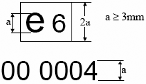
The approval mark in this Appendix affixed to an engine approved as a separate technical unit shows that the type concerned has been approved in Belgium (e 6), pursuant to this Regulation. The first two digits of the approval number (00) indicate that this engine approved as a separate technical unit was approved according to this Regulation. The following four digits (0004) are those allocated by the type-approval authority to engine approved as a separate technical unit as the base approval number.
Appendix 9
EC Type-Approval Certification Numbering System U.K.
1.Section 3 of the EC type-approval number issued according to Articles 6(1), 8(1) and 10(1) shall be composed by the number of the implementing regulatory act or the latest amending regulatory act applicable to the EC type-approval. The number shall be followed by an alphabetical character reflecting the requirements of OBD and SCR systems in accordance with Table 1.U.K.
| Table 1 | ||||||
| Key: | ||||||
| a ‘NOx OTL’ monitoring requirements as set out in Table 1 and 2 of Annex X. | ||||||
| b ‘PM OTL’ monitoring requirements as set out in Table 1 of Annex X. | ||||||
| c ‘Performance monitoring’ requirements as set out in point 2.3.3.3 of Annex X. | ||||||
| d Reagent quality and consumption ‘phase-in’ requirements as set out in points 7.1.1.1 and 8.4.1.1 of Annex XIII. | ||||||
| e Reagent quality and consumption ‘general’ requirements as set out in points 7.1.1 and 8.4.1 of Annex XIII. | ||||||
| Character | NOx OTLa | PM OTLb | Reagent quality and consumption | Implementation dates: new types | Implementation dates: all vehicles | Last date of registration |
|---|---|---|---|---|---|---|
| A | Row ‘phase-in period’ of Tables 1 and 2 | Performance. Monitoringc | Phase ind | 31.12.2012 | 31.12.2013 | 1.9.2015 |
| B | Row ‘phase-in period’ of Tables 1 and 2 | Row ‘phase-in period’ of Table 1 | Phase ind | 1.9.2014 | 1.9.2015 | 31.12.2016 |
| C | Row ‘general requirements’ of Tables 1 and 2 | Row ‘general requirements’ of Table 1 | Generale | 31.12.2015 | 31.12.2016 | |
Appendix 10
Explanatory notes U.K.
(1)Delete where not applicable (there are cases where nothing needs to be deleted when more than one entry is applicable).U.K.
(2)Specify the tolerance.U.K.
(3)Please fill in here the upper and lower values for each variant.U.K.
(4)To be documented in case of a single OBD engine family and if not already documented in the documentation package(s) referred to in line 3.2.12.2.7.0.4.U.K.
(5)Fuel consumption for the combined WHTC including cold and hot part according to Annex VIII.U.K.
(6)To be documented if not documented in the documentation referred to in point 3.2.12.2.7.1.1.U.K.
(7)Delete as appropriate.U.K.
(8)Information concerning engine performance shall only be given for the parent engine.U.K.
(9)Specify the tolerance; to be within ± 3 % of the values declared by the manufacturer.U.K.
(a)If the means of identification of type contains characters not relevant to describe the vehicle, component or separate technical unit types covered by this information document, such characters shall be represented in the documentation by the symbol ‘?’ (e.g. ABC?123??).U.K.
(b)Classified according to definitions listed in Section A of Annex II to Directive 2007/46/EC.U.K.
(l)This figure shall be rounded off to the nearest tenth of a millimetre.U.K.
(m)This value shall be calculated and rounded off to the nearest cm3.U.K.
(n)Determined in accordance with the requirements of Annex XIV.U.K.
ANNEX IIU.K. CONFORMITY OF IN-SERVICE ENGINES OR VEHICLES
1.INTRODUCTIONU.K.
1.1.This Annex sets out requirements for checking and demonstrating the conformity of in-service engines and vehicles.U.K.
2.PROCEDURE FOR IN-SERVICE CONFORMITYU.K.
2.1.The conformity of in-service vehicles or engines of an engine family shall be demonstrated by testing vehicles on the road operated over their normal driving patterns, conditions and payloads. The in-service conformity test shall be representative for vehicles operated on their real driving routes, with their normal load and with the usual professional driver of the vehicle. When the vehicle is operated by a driver other than the usual professional driver of the particular vehicle, this alternative driver shall be skilled and trained to operate vehicles of the category subject to be tested.U.K.
2.2.If the normal in-service conditions of a particular vehicle are considered to be incompatible with the proper execution of the tests, the manufacturer or the approval authority may request that alternative driving routes and payloads are used.U.K.
2.3.The manufacturer shall demonstrate to the approval authority that the chosen vehicle, driving patterns, conditions and payloads are representative for the engine family. The requirements as specified in points 4.1 and 4.5 shall be used to determine whether the driving patterns and payloads are acceptable for in-service conformity testing.U.K.
2.4.The manufacturer shall report the schedule and the sampling plan for conformity testing at the time of the initial type-approval of a new engine family.U.K.
2.5.Vehicles without a communication interface which permits the collection of the necessary ECU data as specified in points 5.2.1 and 5.2.2 of Annex I, with missing data or with a non-standard data protocol shall be considered as non-compliant.U.K.
2.6.Vehicles where the collection of ECU data influences the vehicle emissions or performance shall be considered as non-compliant.U.K.
3.ENGINE OR VEHICLE SELECTIONU.K.
3.1.After the granting of type-approval for an engine family the manufacturer shall perform in-service testing on this engine family within 18 months from first registration of a vehicle fitted with an engine from that family. In case of multistage type-approval first registration means first registration of a completed vehicle.U.K.
The testing shall be repeated at least every 2 years for each engine family periodically on vehicles over their useful life period as specified in Article 4 of Regulation (EC) No 595/2009.
At the request of the manufacturer the testing may stop 5 years after the end of production.
3.1.1.With a minimum sample size of three engines the sampling procedure shall be set so that the probability of a lot passing a test with 20 % of the vehicles or engines defective is 0,90 (producer’s risk = 10 %) while the probability of a lot being accepted with 60 % of the vehicles or engines defective is 0,10 (consumer’s risk = 10 %).U.K.
3.1.2.The test statistic quantifying the cumulative number of non-conforming tests at the n-th test shall be determined for the sample.U.K.
3.1.3.The pass or fail decision of the lot shall be made according to the following requirements:U.K.
(a)
if the test statistic is less than or equal to the pass decision number for the sample size given in Table 1, a pass decision is reached for the lot;
(b)
if the test statistic is greater than or equal to the fail decision number for the sample size given in Table 1, a fail decision is reached for the lot;
(c)
otherwise, an additional engine is tested according to this Annex and the calculation procedure is applied to the sample increased by one more unit.
In Table 1 the pass and fail decision numbers are calculated by means of the International Standard ISO 8422/1991.
Table 1
Pass and fail decision numbers of the sampling plan
Minimum sample size: 3
| Cumulative number of engines tested(sample size) | Pass decision number | Fail decision number |
|---|---|---|
| 3 | — | 3 |
| 4 | 0 | 4 |
| 5 | 0 | 4 |
| 6 | 1 | 4 |
| 7 | 1 | 4 |
| 8 | 2 | 4 |
| 9 | 2 | 4 |
| 10 | 3 | 4 |
The approval authority shall approve the selected engines and vehicle configurations before the launch of the testing procedures. The selection shall be performed by presenting to the approval authority the criteria used for the selection of the particular vehicles.
3.2.The engines and vehicles selected shall be used and registered in the Union. The vehicle shall have been in service for at least 25 000 km.U.K.
3.3.Each vehicle tested shall have a maintenance record to show that the vehicle has been properly maintained and serviced in accordance with the manufacturer’s recommendations.U.K.
3.4.The OBD system shall be checked for proper functioning of the engine. Any malfunction indications and the readiness code in the OBD memory shall be recorded and any required repairs shall be carried out.U.K.
Engines presenting a Class C malfunction shall not be forced to be repaired before testing. The Diagnostic Trouble Code (DTC) shall not be cleared.
Engines having one of the counters required by provisions of Annex XIII not at ‘0’ may not be tested. This shall be reported to the approval authority.
3.5.The engine or vehicle shall exhibit no indications of abuse (such as overloading, misfuelling, or other misuse), or other factors (such as tampering) that could affect emission performance. OBD system fault code and engine running hours information stored in the computer shall be taken into account.U.K.
3.6.All emission control system components on the vehicle shall be in conformity with those stated in the applicable type-approval documents.U.K.
3.7.In agreement with the approval authority, the manufacturer may run in-service conformity testing comprising fewer engines or vehicles than the number given in point 3.1, if the number of engines manufactured within an engine family is less than 500 units per year.U.K.
4.TEST CONDITIONSU.K.
4.1. Vehicle payload U.K.
For the purpose of in-service conformity testing the payload may be reproduced and an artificial load may be used.
In the absence of statistics to demonstrate that the payload is representative for the vehicle, the vehicle payload shall be 50 to 60 % of the maximum vehicle payload.
The maximum payload is the difference between technically permissible maximum laden mass of the vehicle and the mass of the vehicle in running order as specified in accordance to Annex I to Directive 2007/46/EC.
4.2. Ambient conditions U.K.
The test shall be conducted under ambient conditions meeting the following conditions:
Atmospheric pressure greater than or equal to 82,5 kPa,
Temperature greater than or equal to 266 K (– 7 °C) and less than or equal to the temperature determined by the following equation at the specified atmospheric pressure:
T = – 0,4514 × (101,3 – pb) + 311
where:
T is the ambient air temperature, K
pb is the atmospheric pressure, kPa
4.3. Engine coolant temperature U.K.
The engine coolant temperature shall be in accordance with point 2.6.1 of Appendix 1.
4.4.The lubricating oil, fuel and reagent shall be within the specifications issued by the manufacturer.U.K.
4.4.1. Lubricating oil U.K.
Oil samples shall be taken.
4.4.2. Fuel U.K.
The test fuel shall be market fuel covered by Directive 98/70/EC and relevant CEN standards or reference fuel as specified in Annex IX to this Regulation. Fuel samples shall be taken.
4.4.2.1.If the manufacturer in accordance with Section 1 of Annex I to this Regulation has declared the capability to meet the requirements of this Regulation on market fuels declared in point 3.2.2.2.1 of Appendix 4 to Annex I to this Regulation, tests shall be conducted on at least one of the declared market fuels or blend between the declared market fuels and the market fuels included in Directive 98/70/EC and the relevant CEN standards.U.K.
4.4.3. Reagent U.K.
For exhaust after-treatment systems that use a reagent to reduce emissions, a sample of the reagent shall be taken. The reagent shall not be frozen.
4.5. Trip requirements U.K.
The shares of operation shall be expressed as a percentage of the total trip duration.
The trip shall consist of urban driving followed by rural and motorway driving according to the shares specified in points 4.5.1 to 4.5.4 In the case another testing order is justified for practical reasons and after the agreement of the approval authority another order of urban, rural and motorway operation may be used.
For the purpose of this Section, ‘approximately’ shall mean the target value ± 5 %.
Urban operation is characterised by vehicle speeds between 0 and 50 km/h,
Rural operation is characterised by vehicle speeds between 50 and 75 km/h,
Motorway operation is characterised by vehicle speeds above 75 km/h.
4.5.1.For M1 and N1 vehicles the trip shall consist of approximately 45 % urban, 25 % rural and 30 % motorway operation.U.K.
4.5.2.For M2 and M3 vehicles the trip shall consist of approximately 45 % urban, 25 % rural and 30 % motorway operation. M2 and M3 vehicles of Class I, II or Class A as defined in Annex I to Directive 2001/85/EC of the European Parliament and of the Council(3) shall be tested in approximately 70 % urban and 30 % rural operation.U.K.
4.5.3.For N2 vehicles the trip shall consist of approximately 45 % urban, 25 % rural and followed by 30 % motorway operation.U.K.
4.5.4.For N3 vehicles the trip shall consist of approximately 20 % urban, 25 % rural and followed by 55 % motorway operation.U.K.
4.5.5The following distribution of the characteristic trip values from the WHDC database may serve as additional guidance for the evaluation of the trip:U.K.
(a)
accelerating: 26,9 % of the time;
(b)
decelerating: 22,6 % of the time;
(c)
cruising: 38,1 % of the time;
(d)
stop (vehicle speed = 0): 12,4 % of the time.
4.6. Operational requirements U.K.
4.6.1.The trip shall be selected in such a way that the testing is uninterrupted and the data continuously sampled to reach the minimum test duration defined in point 4.6.5.U.K.
4.6.2.Emissions and other data sampling shall start prior to starting the engine. Any cold start emissions may be removed from the emissions evaluation, in accordance with point 2.6 of Appendix 1.U.K.
4.6.3.It shall not be permitted to combine data of different trips or to modify or remove data from a trip.U.K.
4.6.4.If the engine stalls, it may be restarted, but the sampling shall not be interrupted.U.K.
4.6.5.The minimum test duration shall be long enough to complete five times the work performed during the WHTC or produce five times the CO2 reference mass in kg/cycle from the WHTC as applicable.U.K.
4.6.6.The electrical power to the PEMS system shall be supplied by an external power supply unit, and not from a source that draws its energy either directly or indirectly from the engine under test.U.K.
4.6.7.The installation of the PEMS equipment shall not influence the vehicle emissions and/or performance.U.K.
4.6.8.It is recommended to operate the vehicles under normal daytime traffic conditions.U.K.
4.6.9.If the approval authority is not satisfied with the data consistency check results according to Sections 3.2 of Appendix 1 to this Annex, the approval authority may consider the test to be void.U.K.
4.6.10.The same route shall be used for the tests of vehicles within the sample described in points 3.1.1 to 3.1.3.U.K.
5.ECU DATA STREAMU.K.
5.1.Verification of the availability and conformity of the ECU data stream information required for in-service testing.U.K.
5.1.1.The availability of the data stream information according to the requirements of point 5.2 of Annex I shall be demonstrated prior to the in-service test.U.K.
5.1.1.1.If that information cannot be retrieved by the PEMS system in a proper manner, the availability of the information shall be demonstrated by using an external OBD scan-tool as described in Annex X.U.K.
5.1.1.1.1.In the case where this information can be retrieved by the scan-tool in a proper manner, the PEMS system is considered as failing and the test is void.U.K.
5.1.1.1.2.In the case where that information cannot be retrieved in a proper manner from two vehicles with engines from the same engine family, while the scan-tool is working properly, the engine is considered as non-compliant.U.K.
5.1.2.The conformity of the torque signal calculated by the PEMS equipment from the ECU data stream information required in point 5.2.1 of Annex I shall be verified at full load.U.K.
5.1.2.1.The method used to check this conformity is described in Appendix 4.U.K.
5.1.2.2.The conformity of the ECU torque signal is considered to be sufficient if the calculated torque remains within the full load torque tolerance specified in point 5.U.K.
5.1.2.3.If the calculated torque does not remain within the full load torque tolerance specified in point 5.2.5 of Annex I, the engine is considered to have failed the test.U.K.
6.EMISSIONS EVALUATIONU.K.
6.1.The test shall be conducted and the test results shall be calculated in accordance with the provisions of Appendix 1 to this Annex.U.K.
6.2.The conformity factors shall be calculated and presented for both the CO2 mass based method and the Work based method. The pass/fail decision shall be made on the basis of the results of the Work based method.U.K.
6.3.The 90 % cumulative percentile of the exhaust emission conformity factors from each engine system tested, determined in accordance with the measurement and calculation procedures specified in Appendix 1, shall not exceed any of the values set out in Table 2.U.K.
Table 2
Maximum allowed conformity factors for in-service conformity emission testing
7.EVALUATION OF IN-SERVICE CONFORMITY RESULTSU.K.
7.1.On the basis of the in-service conformity report referred to in Section 10, the approval authority shall either:U.K.
(a)
decide that the in-service conformity testing of an engine system family is satisfactory and not take any further action;
(b)
decide that the data provided is insufficient to reach a decision and request additional information and test data from the manufacturer;
(c)
decide that the in-service conformity of an engine system family is unsatisfactory and proceed to the measures referred to in Article 13 and in Section 9 of this Annex.
8.CONFIRMATORY VEHICLE TESTINGU.K.
8.1.Confirmatory testing is done for the purpose of confirmation of the in-service emission functionality of an engine family.U.K.
8.2.Approval authorities may conduct confirmatory testing.U.K.
8.3.The confirmatory test shall be performed as vehicle testing as specified in points 2.1 and 2.2. Representative vehicles shall be selected and used under normal conditions and be tested according to the procedures defined in this Annex.U.K.
8.4.A test result may be regarded as non-satisfactory when, from tests of two or more vehicles representing the same engine family, for any regulated pollutant component, the limit value as determined according to Section 6 is exceeded significantly.U.K.
9.PLAN OF REMEDIAL MEASURESU.K.
9.1.The manufacturer shall submit a report to the approval authority of the Member State where the engines or vehicles subject to remedial action are registered or used when planning to conduct remedial action, and shall submit this report when deciding to take action. The report shall specify the details of the remedial action and describe the engine families to be included in the action. The manufacturer shall report regularly to the approval authority after the start of the remedial action.U.K.
9.2.The manufacturer shall provide a copy of all communications related to the plan of remedial measures, and shall maintain a record of the recall campaign, and supply regular status reports to the approval authority.U.K.
9.3.The manufacturer shall assign a unique identifying name or number to the plan of remedial measures.U.K.
9.4.The manufacturer shall present a plan of remedial measures which shall consist of the information specified in points 9.4.1 to 9.4.11.U.K.
9.4.1.A description of each engine system type included in the plan of remedial measures.U.K.
9.4.2.A description of the specific modifications, alterations, repairs, corrections, adjustments, or other changes to be made to bring the engines into conformity including a brief summary of the data and technical studies which support the manufacturer’s decision as to the particular measures to be taken to correct the non-conformity.U.K.
9.4.3.A description of the method by which the manufacturer informs the engine or vehicle owners about the remedial measures.U.K.
9.4.4.A description of the proper maintenance or use, if any, which the manufacturer stipulates as a condition of eligibility for repair under the plan of remedial measures, and an explanation of the manufacturer’s reasons for imposing any such condition. No maintenance or use conditions may be imposed unless it is demonstrably related to the non-conformity and the remedial measures.U.K.
9.4.5.A description of the procedure to be followed by engine or vehicle owners to obtain correction of the non-conformity. This description shall include a date after which the remedial measures may be taken, the estimated time for the workshop to perform the repairs and where they can be done. The repair shall be done expediently, within a reasonable time after delivery of the vehicle.U.K.
9.4.6.A copy of the information transmitted to the engine or vehicle owner.U.K.
9.4.7.A brief description of the system which the manufacturer uses to assure an adequate supply of components or systems for fulfilling the remedial action. It shall be indicated when there will be an adequate supply of components or systems to initiate the campaign.U.K.
9.4.8.A copy of all instructions to be sent to those persons who are to perform the repair.U.K.
9.4.9.A description of the impact of the proposed remedial measures on the emissions, fuel consumption, driveability, and safety of each engine or vehicle type, covered by the plan of remedial measures with data, technical studies, etc., which support these conclusions.U.K.
9.4.10.Any other information, reports or data the approval authority may reasonably determine is necessary to evaluate the plan of remedial measures.U.K.
9.4.11.Where the plan of remedial measures includes a recall, a description of the method for recording the repair shall be submitted to the approval authority. If a label is used, an example of it shall be submitted.U.K.
9.5.The manufacturer may be required to conduct reasonably designed and necessary tests on components and engines incorporating a proposed change, repair, or modification to demonstrate the effectiveness of the change, repair, or modification.U.K.
10.REPORTING PROCEDURESU.K.
10.1.A technical report shall be submitted to the approval authority for each engine family tested. The report shall show the activities and results of the in-service conformity testing. The report shall include at least the following:U.K.
10.1.1. General U.K.
10.1.1.1.Name and address of the manufacturer.U.K.
10.1.1.2.Address(es) of assembly plant(s).U.K.
10.1.1.3.The name, address, telephone and fax numbers and e-mail address of the manufacturer’s representative.U.K.
10.1.1.4.Type and commercial description (mention any variants).U.K.
10.1.1.5.Engine family.U.K.
10.1.1.6.Parent engine.U.K.
10.1.1.7.Engine family members.U.K.
10.1.1.8.The vehicle identification number (VIN) codes applicable to the vehicles equipped with an engine that is part of the in-service conformity check.U.K.
10.1.1.9.Means and location of identification of type, if marked on the vehicle.U.K.
10.1.1.10.Category of vehicle.U.K.
10.1.1.11.Type of engine: petrol, ethanol (E85), diesel/NG /LPG/ethanol (ED95) (Delete as appropriate).U.K.
10.1.1.12.The numbers of the type-approvals applicable to the engine types within the in-service family, including, where applicable, the numbers of all extensions and field fixes/recalls (reworks).U.K.
10.1.1.13.Details of extensions, field fixes/recalls to those type-approvals for the engines covered within the manufacturer’s information.U.K.
10.1.1.14.The engine build period covered within the manufacturer’s information (e.g. ‘vehicles or engines manufactured during the 2014 calendar year’).U.K.
10.1.2. Engine/vehicle selection U.K.
10.1.2.1.Vehicle or engine location method.U.K.
10.1.2.2.Selection criteria for vehicles, engines, in-service families.U.K.
10.1.2.3.Geographical areas within which the manufacturer has collected vehicles.U.K.
10.1.3. Equipment U.K.
10.1.3.1.PEMS Equipment, brand and type.U.K.
10.1.3.2.PEMS calibration.U.K.
10.1.3.3.PEMS power supply.U.K.
10.1.3.4.Calculation software and version used (e.g. EMROAD 4.0).U.K.
10.1.4. Test data U.K.
10.1.4.1.Date and time of test.U.K.
10.1.4.2.Location of test including details information about the test route.U.K.
10.1.4.3.Weather/ambient conditions (e.g. temperature, humidity, altitude).U.K.
10.1.4.4.Distances covered per vehicle on the test route.U.K.
10.1.4.5.Test fuel specifications characteristics.U.K.
10.1.4.6.Reagent specification (if applicable).U.K.
10.1.4.7.Lubrication oil specification.U.K.
10.1.4.8.Emission test results according to Appendix 1 to this Annex.U.K.
10.1.5. Engine information U.K.
10.1.5.1.Engine fuel type (e.g. diesel, ethanol ED95, NG, LPG, petrol, E85).U.K.
10.1.5.2.Engine combustion system (e.g. compressed ignition or positive ignition).U.K.
10.1.5.3.Type-approval number.U.K.
10.1.5.4.Engine rebuilt.U.K.
10.1.5.5.Engine manufacturer.U.K.
10.1.5.6.Engine model.U.K.
10.1.5.7.Engine production year and month.U.K.
10.1.5.8.Engine identification number.U.K.
10.1.5.9.Engine displacement [litres].U.K.
10.1.5.10.Number of cylinders.U.K.
10.1.5.11.Engine rated power [kW @ rpm].U.K.
10.1.5.12.Engine peak torque [Nm @ rpm].U.K.
10.1.5.13.Idle speed [rpm].U.K.
10.1.5.14.Manufacturer supplied full-load torque curve available (yes/no).U.K.
10.1.5.15.Manufacturer supplied full-load torque curve reference number.U.K.
10.1.5.16.DeNOx system (e.g. EGR, SCR).U.K.
10.1.5.17.Type of catalytic converter.U.K.
10.1.5.18.Type of Particulate trap.U.K.
10.1.5.19.After-treatment modified with respect to type-approval? (yes/no)U.K.
10.1.5.20.Engine ECU information (Software calibration number).U.K.
10.1.6. Vehicle information U.K.
10.1.6.1.Vehicle owner.U.K.
10.1.6.2.Vehicle type (e.g. M3, N3) and application (e.g. rigid or articulated truck, city bus).U.K.
10.1.6.3.Vehicle manufacturer.U.K.
10.1.6.4.Vehicle Identification Number.U.K.
10.1.6.5.Vehicle registration number and country of registration.U.K.
10.1.6.6.Vehicle model.U.K.
10.1.6.7.Vehicle production year and month.U.K.
10.1.6.8.Transmission type (e.g. manual, automatic or other).U.K.
10.1.6.9.Number of forward gears.U.K.
10.1.6.10.Odometer reading at test start [km].U.K.
10.1.6.11.Gross vehicle combination weight rating (GVW) [kg].U.K.
10.1.6.12.Tire size [Not mandatory].U.K.
10.1.6.13.Tail pipe diameter [mm] [Not mandatory].U.K.
10.1.6.14.Number of axles.U.K.
10.1.6.15.Fuel tank(s) capacity [litres] [Not mandatory].U.K.
10.1.6.16.Number of fuel tanks [Not mandatory].U.K.
10.1.6.17.Reagent tank(s) capacity [litres] [Not mandatory].U.K.
10.1.6.18.Number of reagent tanks [Not mandatory].U.K.
10.1.7. Test route characteristics U.K.
10.1.7.1.Odometer reading at test start [km]U.K.
10.1.7.2.Duration [s]U.K.
10.1.7.3.Average ambient conditions (as calculated from the instantaneous measured data)U.K.
10.1.7.4.Ambient conditions sensor information (type and location of sensors)U.K.
10.1.7.5.Vehicle speed information (for example cumulative speed distribution)U.K.
10.1.7.6.Shares of the time of the trip characterised by urban, rural and motorway operation as described in point 4.5.U.K.
10.1.7.7.Shares of the time of the trip characterised by accelerating, decelerating, cruising and stop as described in point 4.5.5.U.K.
10.1.8. Instantaneous measured data U.K.
10.1.8.1.THC concentration [ppm].U.K.
10.1.8.2.CO concentration [ppm].U.K.
10.1.8.3.NOx concentration [ppm].U.K.
10.1.8.4.CO2 concentration [ppm].U.K.
10.1.8.5.CH4 concentration [ppm] for P.I. engines only.U.K.
10.1.8.6.Exhaust gas flow [kg/h].U.K.
10.1.8.7.Exhaust temperature [°C].U.K.
10.1.8.8.Ambient air temperature [°C].U.K.
10.1.8.9.Ambient pressure [kPa].U.K.
10.1.8.10.Ambient humidity [g/kg] [Not mandatory].U.K.
10.1.8.11.Engine torque [Nm].U.K.
10.1.8.12.Engine speed [rpm].U.K.
10.1.8.13.Engine fuel flow [g/s].U.K.
10.1.8.14.Engine coolant temperature [°C].U.K.
10.1.8.15.Vehicle ground speed [km/h] from ECU and GPS.U.K.
10.1.8.16.Vehicle latitude [degree] (Accuracy needs to be sufficient to enable the traceability of the test route).U.K.
10.1.8.17.Vehicle longitude [degree].U.K.
10.1.9. Instantaneous calculated data U.K.
10.1.9.1.THC mass [g/s].U.K.
10.1.9.2.CO mass [g/s].U.K.
10.1.9.3.NOx mass [g/s].U.K.
10.1.9.4.CO2 mass [g/s].U.K.
10.1.9.5.CH4 mass [g/s] for P.I. engines only.U.K.
10.1.9.6.THC cumulated mass [g].U.K.
10.1.9.7.CO cumulated mass [g].U.K.
10.1.9.8.NOx cumulated mass [g].U.K.
10.1.9.9.CO2 cumulated mass [g].U.K.
10.1.9.10.CH4 cumulated mass [g] for P.I. engines only.U.K.
10.1.9.11.Calculated fuel rate[g/s].U.K.
10.1.9.12.Engine power [kW].U.K.
10.1.9.13.Engine work [kWh].U.K.
10.1.9.14.Work window duration [s].U.K.
10.1.9.15.Work window average engine power [%].U.K.
10.1.9.16.Work window THC conformity factor [-].U.K.
10.1.9.17.Work window CO conformity factor [-].U.K.
10.1.9.18.Work window NOx conformity factor [-].U.K.
10.1.9.19.Work window CH4 conformity factor [-] for P.I. engines only.U.K.
10.1.9.20.CO2 mass window duration [s].U.K.
10.1.9.21.CO2 mass window THC conformity factor [-].U.K.
10.1.9.22.CO2 mass window CO conformity factor [-].U.K.
10.1.9.23.CO2 mass window NOx conformity factor [-].U.K.
10.1.9.24.CO2 mass window CH4 conformity factor [-] for P.I. engines only.U.K.
10.1.10. Averaged and integrated data U.K.
10.1.10.1.Average THC concentration [ppm] [Not mandatory].U.K.
10.1.10.2.Average CO concentration [ppm] [Not mandatory].U.K.
10.1.10.3.Average NOx concentration [ppm] [Not mandatory].U.K.
10.1.10.4.Average CO2 concentration [ppm] [Not mandatory].U.K.
10.1.10.5.Average CH4 concentration [ppm] for gas engines only [Not mandatory].U.K.
10.1.10.6.Average Exhaust gas flow [kg/h] [Not mandatory].U.K.
10.1.10.7.Average Exhaust temperature [°C] [Not mandatory].U.K.
10.1.10.8.THC emissions [g].U.K.
10.1.10.9.CO emissions [g].U.K.
10.1.10.10.NOx emissions [g].U.K.
10.1.10.11.CO2 emissions [g].U.K.
10.1.10.12.CH4 emissions [g] for gas engines only.U.K.
10.1.11. Pass-fail results U.K.
10.1.11.1.Minimum, maximum, and 90 % cumulative percentile for:U.K.
10.1.11.2.Work window THC conformity factor [-].U.K.
10.1.11.3.Work window CO conformity factor [-].U.K.
10.1.11.4.Work window NOx conformity factor [-].U.K.
10.1.11.5.Work window CH4 conformity factor [-] for P.I. engines only.U.K.
10.1.11.6.CO2 mass window THC conformity factor [-].U.K.
10.1.11.7.CO2 mass window CO conformity factor [-].U.K.
10.1.11.8.CO2 mass window NOx conformity factor [-].U.K.
10.1.11.9.CO2 mass window CH4 conformity factor [-] for P.I. engines only.U.K.
10.1.11.10.Work window: Minimum and maximum average window power [%].U.K.
10.1.11.11.CO2 mass window: Minimum and maximum window duration [s].U.K.
10.1.11.12.Work window: Percentage of valid windows.U.K.
10.1.11.13.CO2 mass window: Percentage of valid windows.U.K.
10.1.12. Test verifications U.K.
10.1.12.1.THC analyser zero, span and audit results, pre and post test.U.K.
10.1.12.2.CO analyser zero, span and audit results, pre and post test.U.K.
10.1.12.3.NOx analyser zero, span and audit results, pre and post test.U.K.
10.1.12.4.CO2 analyser zero, span and audit results, pre and post test.U.K.
10.1.12.5.Data consistency check results, according to Section 3.2 of Appendix 1 to this Annex.U.K.
[F310.1.12.5.1. Results of the linear regression described in point 3.2.1 of Appendix 1 to this Annex including the slope of the regression line, m, coefficient of determination, r 2 and the intercept, b, of the y-axis of the regression line. U.K.
10.1.12.5.2. Result of the consistency check of the ECU data in accordance with point 3.2.2 of Appendix 1 to this Annex. U.K.
10.1.12.5.3. Result of the consistency check of the Brake-specific fuel consumption in accordance with point 3.2.3 of Appendix 1 to this Annex, including the calculated Brake-specific fuel consumption and the ratio of the calculated Brake-specific fuel consumption from the PEMS measurement and the declared Brake-specific fuel consumption for the WHTC test. U.K.
10.1.12.5.4. Result of the consistency check of the Odometer in accordance with point 3.2.4 of Appendix 1 to this Annex. U.K.
10.1.12.5.5. Result of the consistency check of the ambient pressure in accordance with point 3.2.5 of Appendix 1 to this Annex.] U.K.
10.1.13.List of further attachments where these exist.U.K.
Appendix 1
Test procedure for vehicle emissions testing with portable emissions measurement systems U.K.
1.INTRODUCTIONU.K.
This Appendix describes the procedure to determine gaseous emissions from on-vehicle on-road measurements using Portable Emissions Measurement Systems (hereinafter ‘PEMS’). The gaseous emissions to be measured from the exhaust of the engine include the following components: carbon monoxide, total hydrocarbons and nitrogen oxides for diesel engines with the addition of methane for gas engines. Additionally, carbon dioxide shall be measured to enable the calculation procedures described in Sections 4 and 5.
2.TEST PROCEDUREU.K.
2.1. General requirements U.K.
The tests shall be carried out with a PEMS comprised of:
2.1.1.
Gas analysers to measure the concentrations of regulated gaseous pollutants in the exhaust gas.
2.1.2.
An exhaust mass flow meter based on the averaging Pitot or equivalent principle.
2.1.3.
A Global Positioning System (hereinafter ‘GPS’).
2.1.4.
Sensors to measure the ambient temperature and pressure.
2.1.5.
A connection with the vehicle ECU).
2.2. Test parameters U.K.
The parameters summarised in Table 1 shall be measured and recorded:
Table 1
Test parameters
| a Measured or corrected to a wet basis. | ||
| b Gas engines only. | ||
| c Use the ambient temperature sensor or an intake air temperature sensor. | ||
| d The recorded value shall be either (a) the net torque or (b) the net torque calculated from the actual engine percent torque, the friction torque and the reference torque, according to the SAE J1939-71 standard. | ||
| Parameter | Unit | Source |
|---|---|---|
| THC concentrationa | ppm | Analyser |
| CO concentrationa | ppm | Analyser |
| NOx concentrationa | ppm | Analyser |
| CO2 concentrationa | ppm | Analyser |
| CH4 concentrationa b | ppm | Analyser |
| Exhaust gas flow | kg/h | Exhaust Flow Meter (hereinafter ‘EFM’) |
| Exhaust temperature | °K | EFM |
| Ambient temperaturec | °K | Sensor |
| Ambient pressure | kPa | Sensor |
| Engine torqued | Nm | ECU or Sensor |
| Engine speed | rpm | ECU or Sensor |
| Engine fuel flow | g/s | ECU or Sensor |
| Engine coolant temperature | °K | ECU or Sensor |
| Engine intake air temperaturec | °K | Sensor |
| Vehicle ground speed | km/h | ECU and GPS |
| Vehicle latitude | degree | GPS |
| Vehicle longitude | degree | GPS |
2.3. Preparation of the vehicle U.K.
The preparation of the vehicle shall include the following:
(a)
the check of the OBD system: any identified problems once solved shall be recorded and presented to the approval authority;
(b)
the replacement of oil, fuel and reagent, if any.
2.4. Installation of the measuring equipment U.K.
2.4.1. Main Unit U.K.
Whenever possible, PEMS shall be installed in a location where it will be subject to minimal impact from the following:
(a)
ambient temperature changes;
(b)
ambient pressure changes;
(c)
electromagnetic radiation;
(d)
mechanical shock and vibration;
(e)
ambient hydrocarbons — if using a FID analyser that uses ambient air as FID burner air.
The installation shall follow the instructions issued by the PEMS manufacturer.
2.4.2. Exhaust flow meter U.K.
The exhaust flow meter shall be attached to the vehicle’s tailpipe. The EFM sensors shall be placed between two pieces of straight tube whose length should be at least 2 times the EFM diameter (upstream and downstream). It is recommended to place the EFM after the vehicle silencer, to limit the effect of exhaust gas pulsations upon the measurement signals.
2.4.3. Global Positioning System U.K.
The antenna shall be mounted at the highest possible location, without risking interference with any obstructions encountered during on-road operation.
2.4.4. Connection with the vehicle ECU U.K.
A data logger shall be used to record the engine parameters listed in Table 1. This data logger can make use of the Control Area Network (hereinafter ‘CAN’) bus of the vehicle to access the ECU data broadcasted on the CAN according to standard protocols such as SAE J1939, J1708 or ISO 15765-4.
2.4.5. Sampling of gaseous emissions U.K.
The sample line shall be heated according to the specifications of point 2.3 of Appendix 2 and properly insulated at the connection points (sample probe and back of the main unit), to avoid the presence of cold spots that could lead to a contamination of the sampling system by condensed hydrocarbons.
The sample probe shall be installed in the exhaust pipe in accordance with the requirements of Section 9.3.10 of Annex 4B to UN/ECE Regulation No 49.
If the length of the sample line is changed, the system transport times shall be verified and if necessary corrected.
2.5. Pre-test procedures U.K.
2.5.1. Starting and stabilising the PEMS instruments U.K.
The main units shall be warmed up and stabilised according to the instrument manufacturer specifications until pressures, temperatures and flows have reached their operating set points.
2.5.2. Cleaning the sampling system U.K.
To prevent system contamination, the sampling lines of the PEMS instruments shall be purged until sampling begins, according to the instrument manufacturer specifications.
2.5.3. Checking and calibrating the analysers U.K.
The zero and span calibration and the linearity checks of the analysers shall be performed using calibration gases meeting the requirements of Section 9.3.3 of Annex 4B to UN/ECE Regulation No 49.
2.5.4. Cleaning the EFM U.K.
The EFM shall be purged at the pressure transducer connections in accordance with the instrument manufacturer specifications. This procedure shall remove condensation and diesel particulate matter from the pressure lines and the associated flow tube pressure measurement ports.
2.6. Emissions test run U.K.
2.6.1. Test start U.K.
Emissions sampling, measurement of the exhaust parameters and recording of the engine and ambient data shall start prior to starting the engine. The data evaluation shall start after the coolant temperature has reached 343K (70 °C) for the first time or after the coolant temperature is stabilised within +/– 2K over a period of 5 minutes whichever comes first but no later than 20 minutes after engine start.
2.6.2. Test run U.K.
Emission sampling, measurement of the exhaust parameters and recording of the engine and ambient data shall continue throughout the normal in-use operation of the engine. The engine may be stopped and started, but emissions sampling shall continue throughout the entire test.
Periodic checks of the PEMS gas analysers shall be conducted at least every 2 hours. The data recorded during the checks shall be flagged and shall not be used for the emission calculations.
2.6.3. End of test sequence U.K.
At the end of the test, sufficient time shall be given to the sampling systems to allow their response times to elapse. The engine may be shut down before or after sampling is stopped.
2.7. Verification of the measurements U.K.
2.7.1. Checking of the analysers U.K.
The zero, span and linearity checks of the analysers as described in point 2.5.3 shall be performed using calibration gases meeting the requirements of Section 9.3.3 of Annex 4B to UN/ECE Regulation No 49.
2.7.2. Zero drift U.K.
Zero response is defined as the mean response, including noise, to a zero gas during a time interval of at least 30 seconds. The drift of the zero response shall be less than 2 % of full scale on the lowest range used.
2.7.3. Span drift U.K.
Span response is defined as the mean response, including noise, to a span gas during a time interval of at least 30 seconds. The drift of the span response shall be less than 2 % of full scale on the lowest range used.
2.7.4. Drift verification U.K.
This shall apply only if, during the test, no zero drift correction was made.
As soon as practical but no later than 30 minutes after the test is complete the gaseous analyser ranges used shall be zeroed and spanned to check their drift compared to the pre-test results.
The following provisions shall apply for analyser drift:
(a)
if the difference between the pre-test and post-test results is less than 2 % as specified in points 2.7.2 and 2.7.3, the measured concentrations may be used uncorrected or may be corrected for drift according to point 2.7.5;
(b)
if the difference between the pre-test and post-test results is equal to or greater than 2 % as specified in points 2.7.2 and 2.7.3, the test shall be voided or the measured concentrations shall be corrected for drift according to point 2.7.5.
2.7.5. Drift correction U.K.
If drift correction is applied in accordance with point 2.7.4, the corrected concentration value shall be calculated according to Section 8.6.1 of Annex 4B to UN/ECE Regulation No 49.
The difference between the uncorrected and the corrected brake-specific emission values shall be within ± 6 % of the uncorrected brake-specific emission values. If the drift is greater than 6 %, the test shall be voided. If drift correction is applied, only the drift-corrected emission results shall be used when reporting emissions.
3.CALCULATION OF THE EMISSIONSU.K.
The final test result shall be rounded in one step to the number of places to the right of the decimal point indicated by the applicable emission standard plus one additional significant figure, in accordance with ASTM E 29-06b. No rounding of intermediate values leading to the final brake-specific emission result shall be allowed.
3.1. Time alignment of data U.K.
To minimise the biasing effect of the time lag between the different signals on the calculation of mass emissions, the data relevant for emissions calculation shall be time aligned, as described in points 3.1.1 to 3.1.4.
3.1.1. Gas analysers data U.K.
The data from the gas analysers shall be properly aligned using the procedure in Section 9.3.5 of Annex 4B to UN/ECE Regulation No 49.
3.1.2. Gas analysers and EFM data U.K.
The data from the gas analysers shall be properly aligned with the data of the EFM using the procedure in point 3.1.4.
3.1.3. PEMS and engine data U.K.
The data from the PEMS (gas analysers and EFM) shall be properly aligned with the data from the engine ECU using the procedure in point 3.1.4.
3.1.4. Procedure for improved time-alignment of the PEMS data U.K.
The test data listed in Table 1 are split into 3 different categories:
1
:
Gas analysers (THC, CO, CO2, NOx concentrations);
2
:
Exhaust Flow Meter (Exhaust mass flow and exhaust temperature);
3
:
Engine (Torque, speed, temperatures, fuel rate, vehicle speed from ECU).
The time alignment of each category with the other categories shall be verified by finding the highest correlation coefficient between two series of parameters. All the parameters in a category shall be shifted to maximise the correlation factor. The following parameters shall be used to calculate the correlation coefficients:
To time-align:
(a)
categories 1 and 2 (Analysers and EFM data) with category 3 (Engine data): the vehicle speed from the GPS and from the ECU;
(b)
category 1 with category 2: the CO2 concentration and the exhaust mass;
(c)
category 2 with category 3: the CO2 concentration and the engine fuel flow.
3.2. Data consistency checks U.K.
3.2.1. Analysers and EFM data U.K.
The consistency of the data (exhaust mass flow measured by the EFM and gas concentrations) shall be verified using a correlation between the measured fuel flow from the ECU and the fuel flow calculated using the formula in Section 8.4.1.6 of Annex 4B to UN/ECE Regulation No 49. A linear regression shall be performed for the measured and calculated fuel rate values. The method of least squares shall be used, with the best fit equation having the form:
y = mx + b
where:
— y
is the calculated fuel flow [g/s]
— m
is the slope of the regression line
— x
is the measured fuel flow [g/s]
— b
is the y intercept of the regression line
The slope (m) and the coefficient of determination (r2) shall be calculated for each regression line. It is recommended to perform this analysis in the range from 15 % of the maximum value to the maximum value and at a frequency greater or equal to 1 Hz. For a test to be considered valid, the following two criteria shall be evaluated:
Table 2
Tolerances
| Slope of the regression line, m | 0,9 to 1,1 — Recommended |
|---|---|
| Coefficient of determination r2 | min. 0,90 — Mandatory |
3.2.2. ECU torque data U.K.
The consistency of the ECU torque data shall be verified by comparing the maximum ECU torque values at different engine speeds with the corresponding values on the official engine full load torque curve according to Section 5 of Annex II.
3.2.3. Brake-Specific Fuel Consumption U.K.
The Brake Specific Fuel Consumption (BSFC) shall be checked using:
(a)
the fuel consumption calculated from the emissions data (gas analyser concentrations and exhaust mass flow data), according to the formulae in Section 8.4.1.6 of Annex 4B to UN/ECE Regulation No 49;
(b)
the work calculated using the data from the ECU (Engine torque and engine speed).
3.2.4. Odometer U.K.
The distance indicated by the vehicle odometer shall be checked against the GPS data and verified.
3.2.5. Ambient pressure U.K.
The ambient pressure value shall be checked against the altitude indicated by the GPS data.
3.3. Dry-Wet correction U.K.
If the concentration is measured on a dry basis, it shall be converted to a wet basis according to the formula in Section 8.1 of Annex 4B to UN/ECE Regulation No 49.
3.4. NOx correction for humidity and temperature U.K.
The NOx concentrations measured by the PEMS shall not be corrected for ambient air temperature and humidity.
3.5. Calculation of the instantaneous gaseous emissions U.K.
The mass emissions shall be determined as described in Section 8.4.2.3 of Annex 4B to UN/ECE Regulation No 49.
4.DETERMINATION OF EMISSIONS AND CONFORMITY FACTORSU.K.
4.1. Averaging window principle U.K.
The emissions shall be integrated using a moving averaging window method, based on the reference CO2 mass or the reference work. The principle of the calculation is as follows: The mass emissions are not calculated for the complete data set, but for sub-sets of the complete data set, the length of these sub-sets being determined so as to match the engine CO2 mass or work measured over the reference laboratory transient cycle. The moving average calculations are conducted with a time increment Δt equal to the data sampling period. These sub-sets used to average the emissions data are referred to as ‘averaging windows’ in the following Sections.
Any Section of invalidated data shall not be considered for the calculation of the work or CO2 mass and the emissions of the averaging window.
The following data shall be considered as invalidated data:
(a)
the periodic verification of the instruments and/or after the zero drift verifications;
(b)
the data outside the conditions specified in points 4.2 and 4.3 of Annex II.
The mass emissions (mg/window) shall be determined as described in Section 8.4.2.3 of Annex 4B to UN/ECE Regulation No 49.
Figure 1
Vehicle speed versus time and Vehicle averaged emissions, starting from the first averaging window, versus time

4.2. Work based method U.K.

The duration (t 2,i – t 1,i ) of the ith averaging window is determined by:

where:
W(tj,i ) is the engine work measured between the start and time tj,i , kWh;
Wref is the engine work for the WHTC, kWh;
t 2,i shall be selected such that:

Where Δt is the data sampling period, equal to 1 second or less.
4.2.1. Calculation of the specific emissions U.K.
The specific emissions e gas (mg/kWh) shall be calculated for each window and each pollutant in the following way:

where:
m is the mass emission of the component, mg/window
W(t2,i) – W(t1,i) is the engine work during the ith averaging window, kWh
4.2.2. Selection of valid windows U.K.
The valid windows are the windows whose average power exceeds the power threshold of 20 % of the maximum engine power. The percentage of valid windows shall be equal or greater than 50 %.
4.2.2.1.If the percentage of valid windows is less than 50 %, the data evaluation shall be repeated using lower power thresholds. The power threshold shall be reduced in steps of 1 % until the percentage of valid windows is equal to or greater than 50 %.U.K.
4.2.2.2.In any case, the lower threshold shall not be lower than 15 %.U.K.
4.2.2.3.The test shall be void if the percentage of valid windows is less than 50 % at a power threshold of 15 %.U.K.
4.2.3. Calculation of the conformity factors U.K.
The conformity factors shall be calculated for each individual valid window and each individual pollutant in the following way:

where:
e is the brake-specific emission of the component, mg/kWh;
L is the applicable limit, mg/kWh.
4.3. CO2 mass based method U.K.
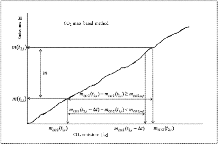
The duration (t2,i – t1,i ) of the ith averaging window is determined by:

where:
m CO2(tj,i ) is the CO2 mass measured between the test start and time tj,i , kg;
m CO2,ref is the CO2 mass determined for the WHTC, kg;
t 2,i shall be selected such as:

Where Δt is the data sampling period, equal to 1 second or less.
The CO2 masses are calculated in the windows by integrating the instantaneous emissions calculated according to the requirements introduced in point 3.5.
4.3.1. Selection of valid windows U.K.
The valid windows shall be the windows whose duration does not exceed the maximum duration calculated from:
where:
D max is the maximum window duration, s;
P max is the maximum engine power, kW.
[F34.3.1.1. If the percentage of valid windows is less than 50 %, the data evaluation shall be repeated using longer window durations. This is achieved by decreasing the value of 0,2 in the formula given in point 4.3.1 by steps of 0,01 until the percentage of valid windows is equal to or greater than 50 %. U.K.
4.3.1.2. In any case, the lowered value in above formula shall not be lower than 0,15. U.K.
4.3.1.3. The test shall be void if the percentage of valid windows is less than 50 % at a maximum window duration calculated in accordance with points 4.3.1, 4.3.1.1 and 4.3.1.2.] U.K.
4.3.2. Calculation of the conformity factors U.K.
The conformity factors shall be calculated for each individual window and each individual pollutant in the following way:


where:
m is the mass emission of the component, mg/window;
m CO2(t 2,i ) – m CO2(t 1,i ) is the CO2 mass during the ith averaging window, kg;
m CO2,ref is the engine CO2 mass determined for the WHTC, kg;
mL is the mass emission of the component corresponding to the applicable limit on the WHTC, mg.
Appendix 2
Portable measurement equipment U.K.
1.GENERALU.K.
The gaseous emissions shall be measured according to the procedure set out in Appendix 1. The present Appendix describes the characteristics of the portable measurement equipment that shall be used to perform such tests.
2.MEASURING EQUIPMENTU.K.
2.1. Gas analysers general specifications U.K.
The PEMS gas analysers specifications shall meet the requirements set out in Section 9.3.1 of Annex 4B to UN/ECE Regulation No 49.
2.2. Gas analysers technology U.K.
The gases shall be analysed using the technologies specified in Section 9.3.1 of Annex 4B to UN/ECE Regulation No 49.
The oxides of nitrogen analyser may also be of the Non-Dispersive Ultra Violet (NDUV) type.
2.3. Sampling of gaseous emissions U.K.
The sampling probes shall meet the requirements defined in Section 3.1.2 of Appendix 3 to Annex 4B to UN/ECE Regulation No 49. The sampling line shall be heated to 190 °C (+/– 10 °C).
2.4. Other instruments U.K.
The measuring instruments shall satisfy the requirements given in Table 7 and Section 9.3.1 to Annex 4B to UN/ECE Regulation No 49.
3.AUXILIARY EQUIPMENTU.K.
3.1. Exhaust Gas Flow Meter (EFM) tailpipe connection U.K.
The installation of the EFM shall not increase the backpressure by more than the value recommended by the engine manufacturer, nor increase the length of the tailpipe by more than 1,2 m. As for the all the components of the PEMS equipment, the installation of the EFM shall comply with the locally applicable road safety regulations and insurance requirements.
3.2. PEMS location and mounting hardware U.K.
The PEMS equipment shall be installed as specified in Section 2.4 of Appendix 1.
3.3. Electrical power U.K.
The PEMS equipment shall be powered using the method described in point 4.6.6 of Annex II.
Appendix 3
Calibration of portable measurement equipment U.K.
1.EQUIPMENT CALIBRATION AND VERIFICATIONU.K.
1.1. Calibration gases U.K.
The PEMS gas analysers shall be calibrated using gases meeting the requirements as set out in Section 9.3.3 of Annex 4B to UN/ECE Regulation No 49.
1.2. Leakage test U.K.
The PEMS leakage tests shall be conducted following the requirements defined in Section 9.3.4 of Annex 4B to UN/ECE Regulation No 49.
1.3. Response time check of the analytical system U.K.
The response time check of the PEMS analytical system shall be conducted in accordance with the requirements set out in Section 9.3.5 of Annex 4B to UN/ECE Regulation No 49.
Appendix 4
Method to check the conformity of the ECU torque signal U.K.
1.INTRODUCTIONU.K.
This Appendix describes in a non-detailed manner the method used to check the conformity of the ECU torque signal during ISC-PEMS testing.
The detailed applicable procedure is left to the engine manufacturer, subject to approval of the approval authority.
2.THE ‘MAXIMUM TORQUE’ METHODU.K.
2.1.The ‘maximum torque’ method consists of demonstrating that a point on the reference maximum torque curve as a function of the engine speed has been reached during vehicle testing.U.K.
[F12.2. If a point on the reference maximum torque curve as a function of the engine speed has not been reached during the ISC PEMS emissions testing, the manufacturer is entitled to modify the load of the vehicle and/or the testing route as necessary in order to perform that demonstration after the ISC PEMS emissions test has been completed.] U.K.
ANNEX IIIU.K. VERIFYING EXHAUST EMISSIONS
1.INTRODUCTIONU.K.
1.1.This Annex sets out the test procedure for verifying exhaust emissions.U.K.
2.GENERAL REQUIREMENTSU.K.
2.1.The general requirements for conducting the tests and interpreting the results shall be those set out in Annex 4B to UN/ECE Regulation No 49 with the exceptions set out in points 2.2 to 2.6.U.K.
[F32.1.1. The requirements for measuring particle number shall be those set out in Annex 4C to UN/ECE Regulation No 49.] U.K.
2.2.The appropriate reference fuels as described in Annex IX to this Regulation shall be used for testing.U.K.
2.3.If the emissions are measured in the raw exhaust gas, Table 5 in Section 8.4.2.3 of Annex 4B to UN/ECE Regulation No 49 of shall be replaced with the following table:U.K.
| Table 1 | |||||||
| Raw exhaust gas u values and component densities | |||||||
| a depending on fuel. | |||||||
| b at λ = 2, dry air, 273 K, 101,3 kPa. | |||||||
| c u accurate within 0,2 % for mass composition of: C = 66 - 76 %; H = 22 - 25 %; N = 0 - 12 %. | |||||||
| d NMHC on the basis of CH2,93 (for total HC the u gas coefficient of CH4 shall be used). | |||||||
| e u accurate within 0,2 % for mass composition of: C3 = 70 - 90 %; C4 = 10 - 30 %. | |||||||
| Fuel | ρ e | Gas | |||||
|---|---|---|---|---|---|---|---|
| NOx | CO | HC | CO2 | O2 | CH4 | ||
| ρ gas [kg/m3] | |||||||
| 2,053 | 1,25 | a | 1,9636 | 1,4277 | 0,716 | ||
| u gas b | |||||||
| Diesel (B7) | 1,2943 | 0,001586 | 0,000966 | 0,000482 | 0,001517 | 0,001103 | 0,000553 |
| Ethanol (ED95) | 1,2768 | 0,001609 | 0,00098 | 0,00078 | 0,001539 | 0,001119 | 0,000561 |
| CNGc | 1,2661 | 0,001621 | 0,000987 | 0,000528d | 0,001551 | 0,001128 | 0,000565 |
| Propane | 1,2805 | 0,001603 | 0,000976 | 0,000512 | 0,001533 | 0,001115 | 0,000559 |
| Butane | 1,2832 | 0,0016 | 0,000974 | 0,000505 | 0,00153 | 0,001113 | 0,000558 |
| LPGe | 1,2811 | 0,001602 | 0,000976 | 0,00051 | 0,001533 | 0,001115 | 0,000559 |
2.4.If the emissions are measured in the dilute exhaust gas, Table 6 in Section 8.5.2.3.1 of Annex 4B to UN/ECE Regulation No 49 shall be replaced with the following table:U.K.
| Table 2 | |||||||
| Dilute exhaust gas u values and component densities | |||||||
| a depending on fuel. | |||||||
| b at λ = 2, dry air, 273 K, 101,3 kPa. | |||||||
| c u accurate within 0,2 % for mass composition of: C = 66 - 76 %; H = 22 - 25 %; N = 0 - 12 %. | |||||||
| d NMHC on the basis of CH2,93 (for total HC the u gas coefficient of CH4 shall be used). | |||||||
| e u accurate within 0,2 % for mass composition of: C3 = 70 - 90 %; C4 = 10 - 30 %. | |||||||
| Fuel | ρ de | Gas | |||||
|---|---|---|---|---|---|---|---|
| NOx | CO | HC | CO2 | O2 | CH4 | ||
| ρ gas [kg/m3] | |||||||
| 2,053 | 1,25 | a | 1,9636 | 1,4277 | 0,716 | ||
| u gas b | |||||||
| Diesel (B7) | 1,293 | 0,001588 | 0,000967 | 0,000483 | 0,001519 | 0,001104 | 0,000553 |
| Ethanol (ED95) | 1,293 | 0,001588 | 0,000967 | 0,00077 | 0,001519 | 0,001104 | 0,000553 |
| CNGc | 1,293 | 0,001588 | 0,000967 | 0,000517d | 0,001519 | 0,001104 | 0,000553 |
| Propane | 1,293 | 0,001588 | 0,000967 | 0,000507 | 0,001519 | 0,001104 | 0,000553 |
| Butane | 1,293 | 0,001588 | 0,000967 | 0,000501 | 0,001519 | 0,001104 | 0,000553 |
| LPGe | 1,293 | 0,001588 | 0,000967 | 0,000505 | 0,001519 | 0,001104 | 0,000553 |
2.5.Ammonia (NH3) shall be determined in accordance with Appendix 1 to this Annex.U.K.
2.6.The emissions from positive-ignition engines fuelled with petrol or E85 shall be determined in accordance with Appendix 2 to this Annex.U.K.
Appendix 1
Procedure for the measurement of ammonia U.K.
1.This Appendix describes the procedure for measurement of ammonia (NH3). For non-linear analysers, the use of linearising circuits shall be permitted.U.K.
2.Two measurement principles are specified for NH3 measurement and either principle may be used provided it meets the criteria specified in point 2.1 or 2.2, respectively. Gas dryers shall not be permitted for NH3 measurement.U.K.
2.1. Laser Diode Spectrometer (LDS) U.K.
2.1.1. Measurement principle U.K.
The LDS employs the single line spectroscopy principle. The NH3 absorption line is chosen in the near infrared spectral range and scanned by a single-mode diode laser.
2.1.2. Installation U.K.
The analyser shall be installed either directly in the exhaust pipe (in-situ) or within an analyser cabinet using extractive sampling in accordance with the instrument manufacturers instructions. If installed in an analyser cabinet, the sample path (sampling line, pre-filter(s) and valves) shall be made of stainless steel or PTFE and shall be heated to 463 ± 10 K (190 ± 10 °C) in order to minimise NH3 losses and sampling artefacts. In addition, the sampling line shall be as short as practically possible.
Influence from exhaust temperature and pressure, installation environment and vibrations on the measurement shall be minimised, or compensation techniques be used.
If applicable, sheath air used in conjunction with in-situ measurement for protection of the instrument, shall not affect the concentration of any exhaust component measured downstream of the device, or sampling of other exhaust components shall be made upstream of the device.
2.1.3. Cross interference U.K.
The spectral resolution of the laser shall be within 0,5 cm-1 in order to minimise cross interference from other gases present in the exhaust gas.
2.2. Fourier Transform Infrared (hereinafter ‘FTIR’) analyser U.K.
2.2.1. Measurement principle U.K.
The FTIR employs the broad waveband infrared spectroscopy principle. It allows simultaneous measurement of exhaust components whose standardised spectra are available in the instrument. The absorption spectrum (intensity/wavelength) is calculated from the measured interferogram (intensity/time) by means of the Fourier transform method.
2.2.2. Installation and sampling U.K.
The FTIR shall be installed in accordance with the instrument manufacturer's instructions. The NH3 wavelength shall be selected for evaluation. The sample path (sampling line, pre-filter(s) and valves) shall be made of stainless steel or PTFE and shall be heated to 463 ± 10 K (190 ± 10 °C) in order to minimise NH3 losses and sampling artefacts. In addition, the sampling line shall be as short as practically possible.
2.2.3. Cross interference U.K.
The spectral resolution of the NH3 wavelength shall be within 0,5 cm-1 in order to minimise cross interference from other gases present in the exhaust gas.
3.EMISSIONS TEST PROCEDURE AND EVALUATIONU.K.
3.1. Checking the analysers U.K.
Prior to the emissions test, the analyser range shall be selected. Emission analysers with automatic or manual range switching shall be permitted. During the test cycle, the range of the analysers shall not be switched.
Zero and span response shall be determined, if the provisions of point 3.4.2 do not apply for the instrument. For the span response, a NH3 gas that meets the specifications of point 4.2.7 shall be used. The use of reference cells that contain NH3 span gas is permitted.
3.2. Collection of emission relevant data U.K.
At the start of the test sequence, the NH3 data collection shall be started, simultaneously. The NH3 concentration shall be measured continuously and stored with at least 1 Hz on a computer system.
3.3. Operations after test U.K.
At the completion of the test, sampling shall continue until system response times have elapsed. Determination of analyser's drift according to point 3.4.1 shall only be required if the information in point 3.4.2 is not available.
3.4. Analyser drift U.K.
3.4.1As soon as practical but no later than 30 minutes after the test cycle is complete or during the soak period, the zero and span responses of the analyser shall be determined. The difference between the pre-test and post-test results shall be less than 2 % of full scale.U.K.
3.4.2.Determination of analyser drift is not required in the following situations:U.K.
(a)
if the zero and span drift specified by the instrument manufacturer in points 4.2.3 and 4.2.4 meets the requirements of point 3.4.1;
(b)
the time interval for zero and span drift specified by the instrument manufacturer in points 4.2.3 and 4.2.4 exceeds the duration of the test.
3.5. Data evaluation U.K.
The average NH3 concentration (ppm/test) shall be determined by integrating the instantaneous values over the cycle. The following equation shall be applied:

where:
c NH3,i is the instantaneous NH3 concentration in the exhaust gas, ppm,
n is the number of measurements.
For the WHTC, the final test result shall be determined with the following equation:
c NH3 = (0,14 × c NH3,cold) + (0,86 × c NH3,hot)
where:
c NH3,cold
is the average NH3 concentration of the cold start test, ppm,
c NH3,hot
is the average NH3 concentration of the hot start test, ppm.
4.ANALYSER SPECIFICATION AND VERIFICATIONU.K.
4.1. Linearity requirements U.K.
The analyser shall comply with the linearity requirements specified in Table 7 of Annex 4B to UN/ECE Regulation No 49. The linearity verification in accordance with Section 9.2.1 of Annex 4B to UN/ECE Regulation No 49, shall be performed at least every 12 months or whenever a system repair or change is made that could influence calibration. With the prior approval of the approval authority, less than 10 reference points are permitted, if an equivalent accuracy can be demonstrated.
For the linearity verification, a NH3 gas that meets the specifications of point 4.2.7 shall be used. The use of reference cells that contain NH3 span gas shall be permitted.
Instruments, whose signals are used for compensation algorithms, shall meet the linearity requirements specified in Table 7 of Annex 4B to the UN/ECE Regulation No 49. Linearity verification shall be done as required by internal audit procedures, by the instrument manufacturer or in accordance with ISO 9000 requirements.
4.2. Analyser specifications U.K.
The analyser shall have a measuring range and response time appropriate for the accuracy required to measure the concentration of NH3 under transient and steady state conditions.
4.2.1. Minimum detection limit U.K.
The analyser shall have a minimum detection limit of < 2 ppm under all conditions of testing.
4.2.2. Accuracy U.K.
The accuracy, defined as the deviation of the analyser reading from the reference value, shall not exceed ± 3 % of the reading or ± 2 ppm, whichever is larger.
4.2.3. Zero drift U.K.
The drift of the zero response and the related time interval shall be specified by the instrument manufacturer.
4.2.4. Span drift U.K.
The drift of the span response and the related time interval shall be specified by the instrument manufacturer.
4.2.5. System response time U.K.
The system response time shall be ≤ 20 s.
4.2.6. Rise time U.K.
The rise time of the analyser shall be ≤ 5 s.
4.2.7. NH3 calibration gas U.K.
A gas mixture with the following chemical composition shall be available:
NH3 and purified nitrogen.
The true concentration of the calibration gas shall be within ± 3 % of the nominal value. The concentration of NH3 shall be given on a volume basis (volume per cent or volume ppm).
The expiration date of the calibration gases stated by the manufacturer shall be recorded.
5.ALTERNATIVE SYSTEMSU.K.
Other systems or analysers may be approved by the approval authority, if it is found that they yield equivalent results in accordance with Section 5.1.1 of Annex 4B to UN/ECE Regulation No 49.
‘Results’ shall refer to average cycle specific NH3 concentrations.
Appendix 2
Determination of emissions from positive-ignition engines fuelled with petrol or E85 U.K.
1.This Appendix describes the procedure for measurement of gaseous and particulate emissions from positive-ignition engines.U.K.
2.1.The tests shall be conducted and evaluated as set out in Annex 4B to UN/ECE Regulation No 49 with the exceptions set out in points 2.1.1 to 2.2.U.K.
2.1.1. Calculation of mass emission (raw exhaust gas) U.K.
The mass of the pollutants (g/test) shall be determined in accordance with Section 8.4.2.3 or 8.4.2.4 of Annex 4B to UN/ECE Regulation No 49 with the u values from Table 3.
Table 3
Raw exhaust gas u values and component densities
2.1.2. Calculation of mass emission (dilute exhaust gas) U.K.
The mass of the pollutants (g/test) shall be determined in accordance with Section 8.5.2.3 of Annex 4B to UN/ECE Regulation No 49 with the u values from Table 4.
Table 4
Dilute exhaust gas u values and component densities
For systems with flow compensation, the u gas values given in Table 4, shall be inserted into equation 62 of Section 8.5.2.3.3 of Annex 4B to UN/ECE Regulation No 49.
2.1.2.1. Background correction U.K.
The emissions shall be background corrected according to the requirements of Section 8.5.2.3.2 of Annex 4B to UN/ECE Regulation No 49. If the fuel composition is not known, the following stoichiometric factors may be used:
F S (E10)
=
13,3
F S (E85)
=
11,5
2.2.For the dilute testing of positive-ignition engines, it is permitted to use analyser systems that meet the general requirements and calibration procedures of Un/ECE Regulation No 83. In this case, the provisions of Section 9 and Appendix 3 of Annex 4B to UN/ECE Regulation No 49 shall not apply.U.K.
However, the test procedures in Section 7 of Annex 4B to UN/ECE Regulation No 49 and the emission calculations provided in Section 2.1 of this Appendix and in Section 8 of Annex 4B to UN/ECE Regulation No 49 shall apply.
ANNEX IVU.K. EMISSIONS DATA REQUIRED AT TYPE-APPROVAL FOR ROADWORTHINESS PURPOSES Measuring carbon monoxide emissions at idling speeds
1.INTRODUCTIONU.K.
1.1.This Annex sets out the procedure for measuring carbon monoxide emissions at idling speeds (normal and high) for positive-ignition engines fuelled with petrol or ethanol (E85) or positive-ignition engines fuelled with NG/Biomethane or LPG installed in M2, N1 or M1 vehicles with a maximum permissible mass not exceeding 7,5 tonnes.U.K.
2.GENERAL REQUIREMENTSU.K.
2.1.The general requirements shall be those set out in Sections 5.3.7.1 to 5.3.7.4 of UN/ECE Regulation No 83, with the exceptions set out in Sections 2.2, 2.3 and 2.4.U.K.
2.2.The atomic ratios set out in Section 5.3.7.3 shall be understood as follows:U.K.
| Hcv = Atomic ratio of hydrogen to carbon |
|
| Ocv = Atomic ratio of oxygen to carbon |
|
2.3.The table in point 1.4.3 of Appendix 5 to Annex I to this Regulation shall be completed on the basis of the requirements set out in points 2.2 and 2.4 of this Annex.U.K.
2.4.The manufacturer shall confirm the accuracy of the Lambda value recorded at the time of type-approval in point 2.1 of this Annex as being representative of typical production vehicles within 24 months of the date of the granting of type-approval. An assessment shall be made on the basis of surveys and studies of production vehicles.U.K.
3.TECHNICAL REQUIREMENTSU.K.
3.1.The technical requirements shall be those set out in Annex 5 to UN/ECE Regulation No 83, with the exception set out in point 3.2.U.K.
3.2.The reference fuels specified in Section 2.1 of Annex 5 to UN/ECE Regulation No 83 shall be understood as referring to the appropriate reference fuel specifications set out in Annex IX to this Regulation.U.K.
ANNEX VU.K. VERIFYING EMISSIONS OF CRANKCASE GASES
1.INTRODUCTIONU.K.
1.1.This Annex sets out the provisions and test procedures for verifying emissions of crankcase gases.U.K.
2.GENERAL REQUIREMENTSU.K.
2.1.No crankcase emissions shall be discharged directly into the ambient atmosphere, with the exception given in point 3.1.1.U.K.
3.SPECIFIC REQUIREMENTSU.K.
3.1.Points 3.1.1 and 3.1.2 shall apply to compression-ignition engines and to positive-ignition engines fuelled with natural gas (NG) or liquefied petroleum gas (LPG).U.K.
3.1.1.Engines equipped with turbochargers, pumps, blowers, or superchargers for air induction may discharge crankcase emissions to the ambient atmosphere if the emissions are added to the exhaust emissions (either physically or mathematically) during all emission testing in accordance with Section 6.10 of Annex 4B to UN/ECE Regulation No 49.U.K.
3.1.2.Crankcase emissions that are routed into the exhaust upstream of any exhaust after-treatment device during all operation are not considered to be discharged directly into the ambient atmosphere.U.K.
3.2.Points 3.2.1 and 3.2.2 shall apply to positive-ignition engines fuelled with petrol or E85.U.K.
3.2.1.The pressure in the crankcase shall be measured over the emissions test cycles at an appropriate location. The pressure in the intake manifold shall be measured to within ± 1 kPa.U.K.
3.2.2.Compliance with point 2.1 shall be deemed satisfactory if, in every condition of measurement set out in point 3.2.1, the pressure measured in the crankcase does not exceed the atmospheric pressure prevailing at the time of measurement.U.K.
ANNEX VIU.K. REQUIREMENTS TO LIMIT OFF-CYCLE EMISSIONS (OCE) AND IN-USE EMISSIONS
1.INTRODUCTIONU.K.
1.1.This Annex sets out the performance requirements and prohibition of defeat strategies for engines and vehicles type-approved according to Regulation (EC) No 595/2009 and this Regulation so as to achieve effective control of emissions under a broad range of engine and ambient operating conditions encountered during normal in-use vehicle operation. This Annex also sets out the test procedures for testing off-cycle emissions during type-approval and in actual use of the vehicle.U.K.
2.DEFINITIONSU.K.
The definitions in Section 3 of Annex 10 to UN/ECE Regulation No 49 shall apply.
3.GENERAL REQUIREMENTSU.K.
3.1.The general requirements shall be those set out in Sections 4 and 4.1 of Annex 10 to UN/ECE Regulation No 49.U.K.
4.PERFORMANCE REQUIREMENTSU.K.
4.1.The performance requirements shall be those set out in Section 5 of Annex 10 to UN/ECE Regulation No 49 with the exceptions in points 4.1.1 to 4.1.4.U.K.
4.1.1.Section 5.1.2(a) of Annex 10 to UN/ECE Regulation No 49 shall be understood as follows:U.K.
(a)
its operation is substantially included in the applicable type-approval tests, including the off-cycle test procedures under Section 6 of Annex VI to Regulation (EU) No 582/2011 and the in-service provisions set out in Article 12 to Regulation (EU) No 582/2011.
4.1.2.Section 5.2.1. of Annex 10 to UN/ECE Regulation No 49 shall be understood as follows:U.K.
Exhaust emissions shall not exceed the applicable emission limits specified in point 4.1.3 of Annex VI to Regulation (EU) No 582/2011.
4.1.3.The applicable emission limits shall be the following:U.K.
(a)
for CO: 2 000 mg/kWh;
(b)
for THC: 220 mg/kWh;
(c)
for NOx: 600 mg/kWh;
(d)
for PM: 16 mg/kWh.
4.1.4.Sections 5.2.2 and 5.2.3 of Annex 10 to UN/ECE Regulation No 49 shall not apply.U.K.
5.AMBIENT AND OPERATING CONDITIONSU.K.
5.1.The ambient and operating conditions for the purpose of this Annex shall be those set out in Section 6. of Annex 10 to UN/ECE Regulation No 49.U.K.
[F16. OFF-CYCLE LABORATORY TESTING AND VEHICLE TESTING OF ENGINES AT TYPE-APPROVAL] U.K.
6.1.The off-cycle test procedure during type-approval shall follow the World-harmonised Not-To-Exceed Methodology as described in Section 7 of Annex 10 to UN/ECE Regulation No 49 with the exceptions in points 6.1.1 to 6.1.6.U.K.
6.1.1.The off-cycle laboratory test requirements shall not apply for the type-approval of positive-ignition engine under Regulation (EC) No 595/2009 and this Regulation.U.K.
6.1.2.Section 7.2.1 of Annex 10 to UN/ECE Regulation No 49 shall be understood as follows:U.K.
To determine compliance with the WNTE emissions limits specified in Section 5.2, the engine shall be operated within the WNTE control area defined in Section 7.1 and its emissions shall be measured and integrated over a minimum period of 30 seconds. A WNTE event is defined as a single set of integrated emissions over the period of time. For example, if the engine operates for 65 consecutive seconds within the WNTE control area and ambient conditions this would constitute a single WNTE event and the emissions would be averaged over the full 65-second period. In the case of laboratory testing, the integrating period defined in Section 7.5 shall apply.
[F16.1.3. Section 7.3 of Annex 10 to UN/ECE Regulation No 49 shall be understood as follows: U.K.
In-use testing
A PEMS demonstration test shall be performed at type-approval by testing the parent engine in a vehicle using the procedure described in Appendix 1 to this Annex.
Additional requirements with respect to in-use vehicle testing will be specified at a later stage in accordance with Article 14(3) to Regulation (EU) No 582/2011.]
[F36.1.3.1. The manufacturer may select the vehicle that shall be used for testing but the vehicle choice shall be subject to the agreement of the approval authority. The characteristics of the vehicle used for the PEMS demonstration test shall be representative for the category of vehicle intended for the engine system. The vehicle may be a prototype vehicle. U.K.
6.1.3.2. At the request of the approval authority, an additional engine within the engine family or an equivalent engine representing a different vehicle category may be tested in a vehicle.] U.K.
6.1.4.Section 7.5.4 of Annex 10 to UN/ECE Regulation No 49 shall be understood as follows:U.K.
The WNTE laboratory test shall meet the validation statistics of Section 7.8.7 of Annex 4B to UN/ECE Regulation No 49.
6.1.5.Section 7.5.5 of Annex 10 to UN/ECE Regulation No 49 shall be understood as follows:U.K.
The measurement of the emissions shall be carried out in accordance with Sections 7.5, 7.7 and 7.8 of Annex 4B to UN/ECE Regulation No 49.
6.1.6.Section 7.5.6 of Annex 10 to UN/ECE Regulation No 49 shall be understood as follows:U.K.
The calculation of the test results shall be carried out in accordance with Section 8 of Annex 4B to UN/ECE Regulation No 49.
7.WORLD-HARMONISED NOT-TO-EXCEED DEFICIENCIESU.K.
Section 8 of Annex 10 to UN/ECE shall not apply.
8.WORLD-HARMONISED NOT-TO-EXCEED EXEMPTIONSU.K.
Section 9 of Annex 10 to UN/ECE Regulation No 49 shall not apply.
9.STATEMENT OF OFF-CYCLE EMISSION COMPLIANCEU.K.
Section 10 of Annex 10 to UN/ECE Regulation No 49 shall be understood as follows:
In the application for type-approval, the manufacturer shall provide a statement that the engine family or vehicle complies with the requirements of Regulation (EU) No 582/2011 limiting off-cycle emissions. In addition to this statement, compliance with the applicable emission limits and in use requirements shall be verified through additional tests.
9.1.Sections 10.1 and 10.2 of Annex 10 to UN/ECE Regulation No 49 shall apply.U.K.
10.DOCUMENTATIONU.K.
The documentation shall be those specified in Section 11 of Annex 10 to UN/ECE Regulation No 49.
[F3Appendix 1
PEMS demonstration test at type-approval U.K.
1. INTRODUCTION U.K.
This Appendix describes the procedure for PEMS demonstration test at type-approval.
2. TEST VEHICLE U.K.
2.1. The vehicle used for demonstrating the PEMS demonstration test shall be representative for the vehicle category intended for the installation of the engine system. The vehicle may be a prototype vehicle or an adapted production vehicle. U.K.
2.2. The availability and conformity of the ECU data-stream information shall be demonstrated (for example following the provision of Section 5 of Annex II to this Regulation). U.K.
3. TEST CONDITIONS U.K.
3.1. Vehicle payload U.K.
The vehicle payload shall be 50-60 % of the maximum vehicle payload in accordance with Annex II.
3.2. Ambient conditions U.K.
The test shall be conducted under ambient conditions as described in point 4.2 of Annex II.
3.3. The engine coolant temperature shall be in accordance with point 4.3 of Annex II. U.K.
3.4. Fuel, lubricants and reagent U.K.
The fuel, lubricating oil and reagent for the exhaust after-treatment system shall follow the provisions of points 4.4 to 4.4.3 of Annex II.
3.5. Trip and operational requirements U.K.
The trip and operational requirements shall be those described in points 4.5 to 4.6.8 of Annex II.
4. EMISSIONS EVALUATION U.K.
4.1. The test shall be conducted and the test results calculated in accordance with Section 6 of Annex II. U.K.
5. REPORT U.K.
5.1. A technical report describing the PEMS demonstration test shall show the activities and results and give at least the following information: U.K.
(a)
General information as described in points 10.1.1 to 10.1.1.14 of Annex II.
(b)
Explanation as to why the vehicle(s) (4) used for the test can be considered to be representative for the category of vehicles intended for the engine system.
(c)
Information about test equipment and test data as described in points 10.1.3 to 10.1.4.8 of Annex II.
(d)
Information about the tested engine as described in points 10.1.5 to 10.1.5.20 of Annex II.
(e)
Information about the vehicle used for the test as described in points 10.1.6 to 10.1.6.18 of Annex II.
(f)
Information about the route characteristics as described in points 10.1.7 to 10.1.7.7 of Annex II.
(g)
Information about instantaneous measured and calculated data as described in points 10.1.8 to 10.1.9.24 of Annex II.
(h)
Information about averaged and integrated data as described in points 10.1.10 to 10.1.10.12 of Annex II.
(i)
Pass-fail results as described in points 10.1.11 to 10.1.11.13 of Annex II.
(j)
Information about test verifications as described in points 10.1.12 to 10.1.12.5 of Annex II.]
ANNEX VIIU.K. VERIFYING THE DURABILITY OF ENGINE SYSTEMS
1.INTRODUCTIONU.K.
1.1.This Annex sets out the procedures for selecting engines to be tested over a service accumulation schedule for the purpose of determining deterioration factors. The deterioration factors shall be applied in accordance with the requirements of point 3.6 of this Annex to the emissions measured according to Annex III.U.K.
1.2.This Annex also sets out the emission and non-emission-related maintenance carried out on engines undergoing a service accumulation schedule. Such maintenance shall conform to the maintenance performed on in-service engines and shall be communicated to owners of new engines and vehicles.U.K.
2.SELECTION OF ENGINES FOR ESTABLISHING USEFUL LIFE DETERIORATION FACTORSU.K.
2.1.Engines shall be selected from the engine family defined in accordance with point 6 of Annex I for emission testing in order to establish useful life deterioration factors.U.K.
2.2.Engines from different engine families may be further combined into families based on the type of exhaust after-treatment system utilised. In order to place engines with different numbers of cylinders and different cylinder configuration but having the same technical specifications and installation for the exhaust after-treatment systems into the same engine-aftertreatment system family, the manufacturer shall provide data to the approval authority that demonstrates that the emissions reduction performance of such engine systems is similar.U.K.
2.3.One engine representing the engine-aftertreatment system family as determined in accordance with point 2.2, shall be selected by the engine manufacturer for testing over the service accumulation schedule defined in point 3.2, and shall be reported to the approval authority before any testing commences.U.K.
2.3.1.If the approval authority decides that the worst case emissions of the engine-aftertreatment system family can be characterised better by another engine then the test engine shall be selected jointly by the approval authority and the engine manufacturer.U.K.
3.ESTABLISHING USEFUL LIFE DETERIORATION FACTORSU.K.
3.1. General U.K.
Deterioration factors applicable to an engine-aftertreatment system family are developed from the selected engines based on a service accumulation schedule that includes periodic testing for gaseous and particulate emissions over the WHTC and WHSC tests.
3.2. Service accumulation schedule U.K.
Service accumulation schedules may be carried out at the choice of the manufacturer by running a vehicle equipped with the selected engine over an in-service accumulation schedule or by running the selected engine over a dynamometer service accumulation schedule.
3.2.1. In-service and dynamometer service accumulation U.K.
3.2.1.1.The manufacturer shall determine the form and extent of the distance, the service accumulation and the ageing cycle for engines, consistent with good engineering practice.U.K.
3.2.1.2.The manufacturer shall determine the test points where gaseous and particulate emissions will be measured over the hot WHTC and WHSC tests. The minimum number of test points shall be three, one at the beginning, one approximately in the middle and one at the end of the service accumulation schedule.U.K.
3.2.1.3.The emission values at the start point and at the useful life end point calculated in accordance with point 3.5.2 shall meet the limit values specified in the table of Annex I to Regulation (EC) No 595/2009 but individual emission results from the test points may exceed those limit values.U.K.
3.2.1.4.At the request of the manufacturer and with the agreement of the approval authority, only one test cycle (either the hot WHTC or WHSC test) needs to be run at each test point, with the other test cycle run only at the beginning and at the end of the service accumulation schedule.U.K.
3.2.1.5.Service accumulation schedules may be different for different engine-aftertreatment system families.U.K.
3.2.1.6.Service accumulation schedules may be shorter than the useful life period, but shall not be shorter than shown in the table in point 3.2.1.8.U.K.
3.2.1.7.For engine dynamometer service accumulation, the manufacturer shall provide the applicable correlation between the service accumulation period (driving distance) and engine dynamometer hours, for example, fuel consumption correlation, vehicle speed versus engine revolutions correlation, etc.U.K.
3.2.1.8. Minimum service accumulation period U.K.
Table 1
Minimum service accumulation period
| Category of vehicle in which engine will be installed | Minimum service accumulation period | Useful life (Article of Regulation (EC) No 595/2009) |
|---|---|---|
| Category N1 vehicles | 160 000 km | Article 4(2)(a) |
| Category N2 vehicles | 188 000 km | Article 4(2)(b) |
| Category N3 vehicles with a maximum technically permissible mass not exceeding 16 tonnes | 188 000 km | Article 4(2)(b) |
| Category N3 vehicles with a maximum technically permissible mass exceeding 16 tonnes | 233 000 km | Article 4(2)(c) |
| Category M1 vehicles | 160 000 km | Article 4(2)(a) |
| Category M2 vehicles | 160 000 km | Article 4(2)(a) |
| Category M3 vehicles of classes I, II, A and B as defined in Annex I to Directive 2001/85/EC, with a maximum technically permissible mass not exceeding 7,5 tonnes | 188 000 km | Article 4(2)(b) |
| Category M3 vehicles of classes III and B as defined in Annex I to Directive 2001/85/EC with a maximum technically permissible mass exceeding 7,5 tonnes | 233 000 km | Article 4(2)(c) |
3.2.1.9.Accelerated ageing is permitted by adjusting the service accumulation schedule on a fuel consumption basis. The adjustment shall be based on the ratio between the typical in-use fuel consumption and the fuel consumption on the ageing cycle, but the fuel consumption on the ageing cycle shall not exceed the typical in-use fuel consumption by more than 30 %.U.K.
3.2.1.10.The service accumulation schedule shall be fully described in the application for type-approval and reported to the type-approval authority before the start of any testing.U.K.
3.2.2.If the type-approval authority decides that additional measurements need to be carried out on the hot WHTC and WHSC tests between the points selected by the manufacturer it shall notify the manufacturer. The revised service accumulation schedule shall be prepared by the manufacturer and agreed by the approval authority.U.K.
3.3. Engine testing U.K.
3.3.1. Engine system stabilisation U.K.
3.3.1.1.For each engine-aftertreatment system family, the manufacturer shall determine the number of hours of vehicle or engine running after which the operation of the engine-aftertreatment system has stabilised. If requested by the approval authority the manufacturer shall make available the data and analysis used to make this determination. As an alternative, the manufacturer may elect to run the engine between 60 and 125 hours or the equivalent mileage on the ageing cycle to stabilise the engine-aftertreatment system.U.K.
3.3.1.2.The end of the stabilisation period determined in point 3.3.1.1 will be deemed to be the start of the service accumulation schedule.U.K.
3.3.2. Service accumulation testing U.K.
3.3.2.1.After stabilisation, the engine shall be run over the service accumulation schedule selected by the manufacturer, as described in point 3.2. At the periodic intervals in the service accumulation schedule determined by the manufacturer, and, where appropriate, also stipulated by the approval authority according to point 3.2.2 the engine shall be tested for gaseous and particulate emissions over the hot WHTC and WHSC tests. In accordance with point 3.2.1.4, if it has been agreed that only one test cycle (hot WHTC or WHSC) be run at each test point, the other test cycle (hot WHTC or WHSC) shall be run at the beginning and end of the service accumulation schedule.U.K.
3.3.2.2.During the service accumulation schedule, maintenance shall be carried out on the engine according to the requirements of point 4.U.K.
3.3.2.3.During the service accumulation schedule, unscheduled maintenance on the engine or vehicle may be performed, for example if the OBD system has specifically detected a problem that has resulted in the malfunction indicator (hereinafter ‘MI’) being activated.U.K.
3.4. Reporting U.K.
3.4.1.The results of all emission tests (hot WHTC and WHSC) conducted during the service accumulation schedule shall be made available to the approval authority. If any emission test is declared to be void, the manufacturer shall provide an explanation of why the test has been declared void. In such a case, another series of emission tests over the hot WHTC and WHSC tests shall be carried out within the following 100 hours of service accumulation.U.K.
3.4.2.The manufacturer shall retain records of all information concerning all the emission tests and maintenance carried out on the engine during the service accumulation schedule. This information shall be submitted to the approval authority along with the results of the emission tests conducted over the service accumulation schedule.U.K.
3.5. Determination of deterioration factors U.K.
3.5.1.For each pollutant measured on the hot WHTC and WHSC tests at each test point during the service accumulation schedule, a ‘best fit’ linear regression analysis shall be made on the basis of all test results. The results of each test for each pollutant shall be expressed to the same number of decimal places as the limit value for that pollutant, as shown in the table of Annex I to Regulation (EC) No 595/2009, plus one additional decimal place. In accordance with point 3.2.1.4 of this Annex, if it has been agreed that only one test cycle (hot WHTC or WHSC) be run at each test point and the other test cycle (hot WHTC or WHSC) run only at the beginning and at the end of the service accumulation schedule, the regression analysis shall be made only on the basis of the test results from the test cycle run at each test point.U.K.
At the request of the manufacturer and with the prior approval of the approval authority a non-linear regression shall be permitted.
3.5.2.The emission values for each pollutant at the start of the service accumulation schedule and at the useful life end point that is applicable for the engine under test shall be calculated from the regression equation. If the service accumulation schedule is shorter than the useful life period, the emission values at the useful life end point shall be determined by extrapolation of the regression equation as determined in point 3.5.1.U.K.
3.5.3.The deterioration factor for each pollutant is defined as the ratio of the applied emission values at the useful life end point and at the start of the service accumulation schedule (multiplicative deterioration factor).U.K.
At the request of the manufacturer and with the prior approval of the approval authority, an additive deterioration factor for each pollutant may be applied. The additive deterioration factor shall be considered as the difference between the calculated emission values at the useful life end point and at the start of the service accumulation schedule.
If the calculation results in a value of less than 1,00 for a multiplicative DF, or less than 0,00 for an additive DF, then the deterioration factor shall be 1,0 or 0,00, respectively.
An example for determination of deterioration factors by using linear regression is shown in Figure 1.
Mixing of multiplicative and additive deterioration factors within one set of pollutants shall not be permitted.
In accordance with point 3.2.1.4, if it has been agreed that only one test cycle (hot WHTC or WHSC) be run at each test point and the other test cycle (hot WHTC or WHSC) run only at the beginning and end of the service accumulation schedule, the deterioration factor calculated for the test cycle that has been run at each test point shall be applicable also for the other test cycle.

3.6. Assigned deterioration factors U.K.
3.6.1.As an alternative to using a service accumulation schedule to determine deterioration factors, engine manufacturers may choose to use the following assigned multiplicative deterioration factors:U.K.
Table 2
Deterioration factors
Assigned additive deterioration factors are not given. It shall not be permitted to transform the assigned multiplicative deterioration factors into additive deterioration factors.
3.7. Application of deterioration factors U.K.
3.7.1.The engines shall meet the respective emission limits for each pollutant, as given in the table of Annex I to Regulation (EC) No 595/2009, after application of the deterioration factors to the test result as measured in accordance with Annex III (egas, ePM). Depending on the type of deterioration factor (DF), the following provisions shall apply:U.K.
(a)
Multiplicative: (egas or ePM) x DF ≤ emission limit
(b)
Additive: (egas or ePM) + DF ≤ emission limit
3.7.2.The manufacturer may choose to carry across the DFs determined for an engine after treatment system family to an engine system that does not fall into the same engine-aftertreatment system family. In such cases, the manufacturer shall demonstrate to the approval authority that the engine system for which the aftertreatment system family was originally tested and the engine system for which the DFs are being carried across have the same technical specifications and installation requirements on the vehicle and that the emissions of such engine or engine system are similar.U.K.
3.7.3.The deterioration factors for each pollutant on the appropriate test cycle shall be recorded in points 1.4.1 and 1.4.2 of the Addendum to Appendix 5 to Annex I and in points 1.4.1 and 1.4.2 of the Addendum to Appendix 7 to Annex I.U.K.
3.8. Checking of conformity of production U.K.
3.8.1.Conformity of production for emissions compliance shall be checked on the basis of the requirements of Section 7 of Annex I.U.K.
3.8.2.The manufacturer may choose to measure the pollutant emissions before any exhaust after-treatment system at the same time as the type-approval test is being performed. In doing so, the manufacturer may develop an informal deterioration factor separately for the engine and the aftertreatment system that may be used by the manufacturer as an aid to end of production line auditing.U.K.
3.8.3.For the purposes of type-approval, only the deterioration factors according to points 3.5 or 3.6 shall be recorded in points 1.4.1 and 1.4.2 of the Addendum to Appendix 5 and points 1.4.1 and 1.4.2 of the Addendum to Appendix 7 to Annex I.U.K.
4.MAINTENANCEU.K.
For the purpose of the service accumulation schedule, maintenance shall be performed in accordance with the manufacturer’s manual for service and maintenance.
4.1. Emission-related scheduled maintenance U.K.
4.1.1.Emission-related scheduled maintenance for purposes of conducting a service accumulation schedule shall occur at the same distance or equivalent intervals to those that will be specified in the manufacturer’s maintenance instructions to the owner of the engine or vehicle. This maintenance schedule may be updated as necessary throughout the service accumulation schedule provided that no maintenance operation is deleted from the maintenance schedule after the operation has been performed on the test engine.U.K.
4.1.2.The engine manufacturer shall specify for the service accumulation schedule the adjustment, cleaning and maintenance (where necessary) and scheduled exchange of the following items:U.K.
(a)
filters and coolers in the exhaust gas recirculation system;
(b)
positive crankcase ventilation valve, if applicable;
(c)
fuel injector tips (cleaning only);
(d)
fuel injectors;
(e)
turbocharger;
(f)
electronic engine control unit and its associated sensors and actuators;
(g)
particulate aftertreatment system (including related components);
(h)
deNOx system;
(i)
exhaust gas recirculation system, including all related control valves and tubing;
(j)
any other exhaust after-treatment system.
4.1.3.Critical emission-related scheduled maintenance shall only be performed if being performed in-use and being communicated to the owner of the vehicle.U.K.
4.2. Changes to scheduled maintenance U.K.
4.2.1.The manufacturer shall submit a request to the approval authority for approval of any new scheduled maintenance that it wishes to perform during the service accumulation schedule and subsequently recommend to owners of engines or vehicles. The request shall be accompanied by data supporting the need for the new scheduled maintenance and the maintenance interval.U.K.
4.3. Non-emission-related scheduled maintenance U.K.
4.3.1.Non-emission-related scheduled maintenance which is reasonable and technically necessary such as oil change, oil filter change, fuel filter change, air filter change, cooling system maintenance, idle speed adjustment, governor, engine bolt torque, valve lash, injector lash, timing, adjustment of the tension of any drive-belt, etc., may be performed on engines or vehicles selected for the service accumulation schedule at the least frequent intervals recommended by the manufacturer to the owner.U.K.
4.4. Repair U.K.
4.4.1.Repairs to the components of an engine selected for testing over a service accumulation schedule other than the engine emission control system or fuel system shall be performed only as a result of component failure or engine system malfunction.U.K.
4.4.2.If the engine itself, the emission control system or the fuel system fail during the service accumulation schedule, the service accumulation shall be considered void, and a new service accumulation shall be started with a new engine system.U.K.
ANNEX VIIIU.K. CO2 EMISSIONS AND FUEL CONSUMPTION
1.INTRODUCTIONU.K.
1.1.This Annex sets out the provisions and test procedures for reporting CO2 emissions and fuel consumption.U.K.
2.GENERAL REQUIREMENTSU.K.
2.1.CO2 emissions and fuel consumption shall be determined over the WHTC and WHSC test cycles in accordance with Section 7.2 to 7.8 of Annex 4B to UN/ECE Regulation No 49.U.K.
2.2.The test results shall be reported as cycle averaged brake specific values and expressed in the unit of g/kWh.U.K.
3.DETERMINATION OF CO2 EMISSIONSU.K.
3.1. Raw measurement U.K.
This Section shall apply, if CO2 is measured in the raw exhaust gas.
3.1.1. Measurement U.K.
CO2 in the raw exhaust gas emitted by the engine submitted for testing shall be measured with a non-dispersive infrared (NDIR) analyser in accordance with Section 9.3.2.3 and Appendix 3 to Annex 4B to UN/ECE Regulation No 49.
The measurement system shall meet the linearity requirements of Section 9.2 and Table 7of Annex 4B to UN/ECE Regulation No 49.
The measurement system shall meet the requirements of Sections 9.3.1, 9.3.4 and 9.3.5 of Annex 4B to UN/ECE Regulation No 49.
3.1.2. Data evaluation U.K.
The relevant data shall be recorded and stored in accordance with Section 7.6.6 of Annex 4B to UN/ECE Regulation No 49. The traces of the recorded concentrations and the trace of the exhaust gas mass flow rate shall be time aligned with the transformation time as defined in Section 3.1.30 of Annex 4B to UN/ECE Regulation No 49.
3.1.3. Calculation of cycle averaged emission U.K.
If measured on a dry basis, the dry/wet correction according to Section 8.1 of Annex 4B to UN/ECE Regulation No 49 shall be applied to the instantaneous concentration values before any further calculation is done.
The mass of CO2 (g/test) shall be determined by calculating the instantaneous mass emissions from the raw CO2 concentration and the exhaust gas mass flow, aligned with respect to their transformation times as determined in accordance with Section 8.4.2.2 of Annex 4B to UN/ECE Regulation No 49, integrating the instantaneous values over the cycle, and multiplying the integrated value with the u values of CO2 from Table 5 of Annex 4B to UN/ECE Regulation No 49.
The following equation shall be applied:

where:
u CO2
is the ratio between CO2 density and density of the exhaust gas
c CO2,i
is the instantaneous CO2 concentration in the exhaust gas, ppm
q mew,i
is the instantaneous exhaust mass flow, kg/s
f
is the data sampling rate, Hz
n
is the number of measurements
Optionally, the CO2 mass may be calculated in accordance with Section 8.4.2.4 of Annex 4B to UN/ECE Regulation No 49 by using a CO2 molar mass (M CO2) of 44,01 g/mol.
3.2. Dilute measurement U.K.
This Section applies, if CO2 is measured in the dilute exhaust gas.
3.2.1. Measurement U.K.
CO2 in the dilute exhaust gas emitted by the engine submitted for testing shall be measured with a non-dispersive infrared (NDIR) analyser in accordance with Section 9.3.2.3 and Appendix 3 to Annex 4B to UN/ECE Regulation No 49. Dilution of the exhaust shall be done with filtered ambient air, synthetic air or nitrogen. The flow capacity of the full flow system shall be large enough to completely eliminate water condensation in the dilution and sampling systems.
The measurement system shall meet the linearity requirements of Section 9.2 and Table 7 of Annex 4B to UN/ECE Regulation No 49.
The measurement system shall meet the requirements of Sections 9.3.1, 9.3.4 and 9.3.5 of Annex 4B to UN/ECE Regulation No 49.
3.2.2. Data evaluation U.K.
The relevant data shall be recorded and stored in accordance with Section 7.6.6 of Annex 4B to UN/ECE Regulation No 49.
3.2.3. Calculation of cycle averaged emission U.K.
If measured on a dry basis, the dry/wet correction according to Section 8.1 of Annex 4B to UN/ECE Regulation No 49 shall be applied.
For systems with constant mass flow (with heat exchanger), the mass of CO2 (g/test) shall be determined with the following equation:

where:
c CO2,e
is the average background corrected CO2 concentration, ppm
0,001519
is the ratio between CO2 density and density of air (u factor)
m ed
is the total diluted exhaust mass over the cycle, kg
For systems with flow compensation (without heat exchanger), the mass of CO2 (g/test) shall be determined by calculating the instantaneous mass emissions and integrating the instantaneous values over the cycle. Also, the background correction shall be applied directly to the instantaneous concentration values. The following equation shall be applied:
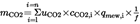
where:
c CO2,e
is the CO2 concentration measured in the diluted exhaust gas, ppm
c CO2,d
is the CO2 concentration measured in the dilution air, ppm
0,001519
is the ratio between CO2 density and density of air (u factor)
m ed,i
is the instantaneous mass of the diluted exhaust gas, kg
m ed
is the total mass of diluted exhaust gas over the cycle, kg
D
is the dilution factor
Optionally, the u factor may be calculated with equation 57 in Section 8.5.2.3.1 of Annex 4B to UN/ECE Regulation No 49 by using a CO2 molar mass (M CO2) of 44,01 g/mol.
CO2 background correction shall be applied in accordance with Section 8.5.2.3.2 of Annex 4B to UN/ECE Regulation No 49.
3.3. Calculation of brake specific emissions U.K.
The cycle work needed for the calculation of brake specific CO2 emissions shall be determined in accordance with Section 7.8.6 of Annex 4B to UN/ECE Regulation No 49.
3.3.1. WHTC U.K.
The brake specific emissions e CO2 (g/kWh) shall be calculated as follows:

where:
m CO2,cold
is the CO2 mass emissions of the cold start test, g/test
m CO2,hot
is the CO2 mass emissions of the hot start test, g/test
W act,cold
is the actual cycle work of the cold start test, kWh
W act,hot
is the actual cycle work of the hot start test, kWh
3.3.2. WHSC U.K.
The brake specific emissions e CO2 (g/kWh) shall be calculated as follows:

where:
m CO2
is the CO2 mass emissions, g/test
W act
is the actual cycle work, kWh
4.DETERMINATION OF FUEL CONSUMPTIONU.K.
4.1. Measurement U.K.
Measurement of the instantaneous fuel flow shall be done by systems that preferably measure mass directly such as the following:
(a)
mass flow sensor;
(b)
fuel weighing;
(c)
Coriolis meter.
The fuel flow measurement system shall have the following:
(a)
an accuracy of ± 2 % of the reading or ± 0,3 % of full scale whichever is better;
(b)
a precision of ± 1 % of full scale or better;
(c)
a rise time that does not exceed 5 s.
The fuel flow measurement system shall meet the linearity requirements of Section 9.2 and Table 7 of Annex 4B to UN/ECE Regulation No 49.
Precautions shall be taken to avoid measurement errors. Such precautions shall at least include the following:
(a)
the careful installation of the device according to the instrument manufacturers’ recommendations and to good engineering practice;
(b)
flow conditioning as needed to prevent wakes, eddies, circulating flows, or flow pulsations that affect accuracy or precision of the fuel flow system;
(c)
account for any fuel that bypasses the engine or returns from the engine to the fuel storage tank.
4.2. Data evaluation U.K.
The relevant data shall be recorded and stored in accordance with Section 7.6.6 of Annex 4B to UN/ECE Regulation No 49.
4.3. Calculation of cycle averaged fuel consumption U.K.
The mass of fuel (g/test) shall be determined by the sum of the instantaneous values over the cycle, as follows:

where:
q mf,i
is the instantaneous fuel flow, kg/s
f
is the data sampling rate, Hz
n
is the number of measurements
4.4. Calculation of brake specific fuel consumption U.K.
The cycle work needed for the calculation of the brake specific fuel consumption shall be determined in accordance with Section 7.8.6 of Annex 4B to UN/ECE Regulation No 49.
4.4.1. WHTC U.K.
The brake specific fuel consumption e f (g/kWh) shall be calculated as follows:

where:
q mf, cold
is the fuel mass of the cold start test, g/test
q mf, hot
is the fuel mass of the hot start test, g/test
W act, cold
is the actual cycle work of the cold start test, kWh
W act, hot
is the actual cycle work of the hot start test, kWh
4.4.2. WHSC U.K.
The brake specific fuel consumption e f (g/kWh) shall be calculated as follows:

where:
q mf
is the fuel mass, g/test
W act
is the actual cycle work, kWh
Appendix 1
Provisions on CO2 emissions and fuel consumption for extension of an EC type-approval for a vehicle type approved under Regulation (EC) No 595/2009 and this Regulation with a reference mass exceeding 2 380 kg but not exceeding 2 610 kg U.K.
1.INTRODUCTIONU.K.
1.1.This Appendix sets out the provisions and test procedures for reporting CO2 emissions and fuel consumption for extension of an EC type-approval for a vehicle type approved under Regulation (EC) No 595/2009 and this Regulation to a vehicle with a reference mass exceeding 2 380 kg but not exceeding 2 610 kg.U.K.
2.GENERAL REQUIREMENTSU.K.
2.1.In order to receive an extension of an EC type-approval for a vehicle in respect of its engine type approved under this Regulation to a vehicle with a reference mass exceeding 2 380 kg but not exceeding 2 610 kg the manufacturer shall meet the requirements of Annex XII to Commission Regulation (EC) No 692/2008(5) with the exceptions specified below.U.K.
2.1.1.Section 2.2.1 of Annex XII to Regulation (EC) No 692/2008 shall be understood as referring to the reference fuels described in Annex IX.U.K.
2.1.2.Section 5.2.4 of UN/ECE Regulation 101 referred to in point 2.3 of Annex XII to Regulation (EC) No 692/2008 shall be understood as follows:U.K.
(1)
density: measured on the test fuel according to ISO 3675 or an equivalent method. For petrol, diesel, ethanol (E85) and ethanol for dedicated C.I. engines (ED95) the density measured at 288 K (15 °C) shall be used; for LPG and natural gas/biomethane a reference density will be used, as follows:
0,538 kg/litre for LPG.
0,654 kg/m3 for NG.
(2)
hydrogen-carbon-oxygen ratio: fixed values shall be used which are:
C1H1,93O0,032 for petrol (E10),
C1H1,86O0,006 for diesel (B7),
C1H2,525 for LPG (liquefied petroleum gas),
CH4 for NG (natural gas) and biomethane,
C1H2,74O0,385 for ethanol (E85),
C1H2,92O0,46 for ethanol for dedicated C.I. engines (ED95).
2.1.3.Point 1.4.3 of Annex 6 to UN/ECE Regulation 101 referred to in Section 3.3 of Annex XII to Regulation (EC) No 692/2008 shall be understood as:U.K.
‘1.4.3.
The fuel consumption, expressed in litres per 100 km (in the case of petrol, LPG, ethanol (E85 and ED95) and diesel) or in m3 per 100 km (in the case of NG/biomethane) is calculated by means of the following formulae:
(a)
for vehicles with a positive-ignition engine fuelled with petrol (E10):
FC = (0,120/D) · [(0,831 · HC) + (0,429 · CO) + (0,273 · CO2)]
(b)
for vehicles with a positive-ignition engine fuelled with LPG:
FCnorm = (0,1212/0,538) · [(0,825 · HC) + (0,429 · CO) + (0,273 · CO2)]
If the composition of the fuel used for the test differs from the composition that is assumed for the calculation of the normalised consumption, on the manufacturer’s request a correction factor cf may be applied, as follows:
FCnorm = (0,1212/0,538) · (cf) · [(0,825 · HC) + (0,429 · CO) + (0,273 · CO2)]
The correction factor cf, which may be applied, is determined as follows:
cf = 0,825 + 0,0693 nactual
where:
nactual is the actual H/C ratio of the fuel used.
(c)
for vehicles with a positive-ignition engine fuelled with NG/biomethane:
FCnorm = (0,1336/0,654) · [(0,749 · HC) + (0,429 · CO) + (0,273 · CO2)]
(d)
for vehicles with a positive-ignition engine fuelled with ethanol (E85):
FC = (0,1742/D) · [(0,574 · HC) + (0,429 · CO) + (0,273 · CO2)]
(e)
for vehicles with a compression-ignition engine fuelled with diesel (B7):
FC = (0,1165/D) · [(0,859 · HC) + (0,429 · CO) + (0,273 · CO2)]
(f)
for vehicles with a dedicated compression-ignition engine fuelled with ethanol (ED95):
FC = (0,186/D) · [(0,538 · HC) + (0,429 · CO) + (0,273 · CO2)]
In these formulae:
FC
is the fuel consumption in litre per 100 km (in the case of petrol, ethanol, LPG, diesel or biodiesel) or in m3 per 100 km (in the case of natural gas)
HC
is the measured emission of hydrocarbons in g/km
CO
is the measured emission of carbon monoxide in g/km
CO2
is the measured emission of carbon dioxide in g/km
D
is the density of the test fuel.
In the case of gaseous fuels this is the density at 288K (15 °C)’.
2.1.4.The reporting requirements in Section 3.4 of Annex XII to Regulation (EC) No 692/2008 shall be understood as referring to Appendix 4 to Annex I to this Regulation.U.K.
ANNEX IXU.K. SPECIFICATIONS OF REFERENCE FUELS
Technical data on fuels for testing compression-ignition engines
| Type: Diesel (B7) | ||||
| a The values quoted in the specifications are ‘true values’. In establishment of their limit values the terms of ISO 4259 Petroleum products — Determination and application of precision data in relation to methods of test have been applied and in fixing a minimum value, a minimum difference of 2R above zero has been taken into account; in fixing a maximum and minimum value, the minimum difference is 4R (R = reproducibility). Notwithstanding this measure, which is necessary for technical reasons, the manufacturer of fuels shall nevertheless aim at a zero value where the stipulated maximum value is 2R and at the mean value in the case of quotations of maximum and minimum limits. Should it be necessary to clarify whether a fuel meets the requirements of the specifications, the terms of ISO 4259 shall be applied. | ||||
| b The range for cetane number is not in accordance with the requirements of a minimum range of 4R. However, in the case of a dispute between fuel supplier and fuel user, the terms of ISO 4259 may be used to resolve such disputes provided replicate measurements, of sufficient number to archive the necessary precision, are made in preference to single determinations. | ||||
| c Even though oxidation stability is controlled, it is likely that shelf life will be limited. Advice shall be sought from the supplier as to storage conditions and life. | ||||
| d FAME content to meet the specification of EN 14214. | ||||
| Parameter | Unit | Limitsa | Test method | |
|---|---|---|---|---|
| Minimum | Maximum | |||
| Cetane index | 46,0 | — | EN ISO 4264 | |
| Cetane numberb | 52,0 | 56,0 | EN-ISO 5165 | |
| Density at 15 °C | kg/m3 | 833 | 837 | EN-ISO 3675 EN ISO 12185 |
| Distillation: | ||||
— 50 % point | °C | 245 | — | EN-ISO 3405 |
— 95 % point | °C | 345 | 350 | EN-ISO 3405 |
— final boiling point | °C | — | 360 | EN-ISO 3405 |
| Flash point | °C | 55 | — | EN 22719 |
| CFPP | °C | — | –5 | EN 116 |
| Viscosity at 40 °C | mm2/s | 2,3 | 3,3 | EN-ISO 3104 |
| Polycyclic aromatic hydrocarbons | % m/m | 2,0 | 4,0 | EN 12916 |
| Sulphur content | mg/kg | — | 10 | EN-ISO 20846/EN-ISO 20884 |
| Copper corrosion (3h at 50 °C) | Rating | — | Class 1 | EN-ISO 2160 |
| Conradson carbon residue (10 % DR) | % m/m | — | 0,2 | EN-ISO 10370 |
| Ash content | % m/m | — | 0,01 | EN-ISO 6245 |
| Total contamination | mg/kg | — | 24 | EN 12662 |
| Water content | % m/m | — | 0,02 | EN-ISO 12937 |
| Neutralisation (strong acid) number | mg KOH/g | — | 0,1 | ASTM D 974 |
| Oxidation stabilityc | mg/ml | — | 0,025 | EN-ISO 12205 |
| Lubricity (HFRR wear scan diameter at 60 °C) | μm | — | 400 | EN ISO 12156 |
| Oxidation stability at 110 °Cc | H | 20,0 | EN 15751 | |
| FAMEd | % v/v | 6,0 | 7,0 | EN 14078 |
| Type: Ethanol for dedicated compression-ignition engines (ED95) a | ||||
| a Additives, such as cetane improver as specified by the engine manufacturer, may be added to the ethanol fuel, as long as no negative side effects are known. If these conditions are satisfied, the maximum allowed amount is 10 % m/m. | ||||
| b The values quoted in the specifications are ‘true values’. In establishment of their limit values the terms of ISO 4259 Petroleum products — Determination and application of precision data in relation to methods of test have been applied and in fixing a minimum value, a minimum difference of 2R above zero has been taken into account; in fixing a maximum and minimum value, the minimum difference is 4R (R = reproducibility). Notwithstanding this measure, which is necessary for technical reasons, the manufacturer of fuels shall nevertheless aim at a zero value where the stipulated maximum value is 2R and at the mean value in the case of quotations of maximum and minimum limits. Should it be necessary to clarify whether a fuel meets the requirements of the specifications, the terms of ISO 4259 shall be applied. | ||||
| c Equivalent EN/ISO methods will be adopted when issued for properties listed above. | ||||
| d Should it be necessary to clarify whether a fuel meets the requirements of the specifications, the terms of EN 15489 shall be applied. | ||||
| Parameter | Unit | Limitsb | Test methodc | |
|---|---|---|---|---|
| Minimum | Maximum | |||
| Total alcohol (Ethanol incl. content on higher saturated alcohols) | % m/m | 92,4 | EN 15721 | |
| Other higher saturated mono-alcohols (C3-C5) | % m/m | 2,0 | EN 15721 | |
| Methanol | % m/m | 0,3 | EN 15721 | |
| Density at 15 °C | kg/m3 | 793,0 | 815,0 | EN-ISO 12185 |
| Acidity, calculated as acetic acid | % m/m | 0,0025 | EN 15491 | |
| Appearance | Bright and clear | |||
| Flashpoint | °C | 10 | EN 3679 | |
| Dry residue | mg/kg | 15 | EN 15691 | |
| Water content | % m/m | 6,5 | EN 15489d EN-ISO 12937 EN 15692 | |
| Aldehydes calculated as acetaldehyde | % m/m | 0,0050 | ISO 1388-4 | |
| Esters calculated as ethylacetat | % m/m | 0,1 | ASTM D1617 | |
| Sulphur content | mg/kg | 10,0 | EN 15485 EN 15486 | |
| Sulphates | mg/kg | 4,0 | EN 15492 | |
| Particulate contamination | mg/kg | 24 | EN 12662 | |
| Phosphorus | mg/l | 0,2 | EN 15487 | |
| Inorganic chloride | mg/kg | 1,0 | EN 15484 or EN 15492 | |
| Copper | mg/kg | 0,1 | EN 15488 | |
| Electrical Conductivity | μS/cm | 2,5 | DIN 51627-4 or prEN 15938 | |
Technical data on fuels for testing positive-ignition engines
| Type: Petrol (E10) | ||||
| a The values quoted in the specifications are ‘true values’. In establishment of their limit values the terms of ISO 4259 Petroleum products — Determination and application of precision data in relation to methods of test have been applied and in fixing a minimum value, a minimum difference of 2R above zero has been taken into account; in fixing a maximum and minimum value, the minimum difference is 4R (R = reproducibility). Notwithstanding this measure, which is necessary for technical reasons, the manufacturer of fuels shall nevertheless aim at a zero value where the stipulated maximum value is 2R and at the mean value in the case of quotations of maximum and minimum limits. Should it be necessary to clarify whether a fuel meets the requirements of the specifications, the terms of ISO 4259 shall be applied. | ||||
| b Equivalent EN/ISO methods will be adopted when issued for properties listed above. | ||||
| c A correction factor of 0,2 for MON and RON shall be subtracted for the calculation of the final result in accordance with EN 228:2008. | ||||
| d The fuel may contain oxidation inhibitors and metal deactivators normally used to stabilise refinery gasoline streams, but detergent/dispersive additives and solvent oils shall not be added. | ||||
| e Ethanol meeting the specification of EN 15376 is the only oxygenate that shall be intentionally added to the reference fuel. | ||||
| f The actual sulphur content of the fuel used for the Type 1 test shall be reported. | ||||
| g There shall be no intentional addition of compounds containing phosphorus, iron, manganese, or lead to this reference fuel. | ||||
| Parameter | Unit | Limitsa | Test methodb | |
|---|---|---|---|---|
| Minimum | Maximum | |||
| Research octane number, RON | 95,0 | 97,0 | EN-ISO 5164:2005c | |
| Motor octane number, MON | 84,0 | 86,0 | EN-ISO 5163:2005c | |
| Density at 15 °C | kg/m3 | 743 | 756 | EN-ISO 3675 EN-ISO 12185 |
| Vapour pressure | kPa | 56,0 | 60,0 | EN-ISO 13016-1 (DVPE) |
| Water content | % v/v | 0,015 | ASTM E 1064 | |
| Distillation: | ||||
— evaporated at 70 °C | % v/v | 24,0 | 44,0 | EN-ISO 3405 |
— evaporated at 100 °C | % v/v | 56,0 | 60,0 | EN-ISO 3405 |
— evaporated at 150 °C | % v/v | 88,0 | 90,0 | EN-ISO 3405 |
— final boiling point | °C | 190 | 210 | EN-ISO 3405 |
| Residue | % v/v | — | 2,0 | EN-ISO 3405 |
| Hydrocarbon analysis: | ||||
— olefins | % v/v | 3,0 | 18,0 | EN 14517 EN 15553 |
— aromatics | % v/v | 25,0 | 35,0 | EN 14517 EN 15553 |
— benzene | % v/v | 0,4 | 1,0 | EN 12177 EN 238, EN 14517 |
— saturates | % v/v | Report | EN 14517 EN 15553 | |
| Carbon/hydrogen ratio | Report | |||
| Carbon/oxygen ratio | Report | |||
| Induction periodd | minutes | 480 | — | EN-ISO 7536 |
| Oxygen contente | % m/m | 3,7 | EN 1601 EN 13132 EN 14517 | |
| Existent gum | mg/ml | — | 0,04 | EN-ISO 6246 |
| Sulphur contentf | mg/kg | — | 10 | EN-ISO 20846 EN ISO 20884 |
| Copper corrosion (3 h at 50 °C) | rating | — | Class 1 | EN-ISO 2160 |
| Lead content | mg/l | — | 5 | EN 237 |
| Phosphorus contentg | mg/l | — | 1,3 | ASTM D 3231 |
| Ethanold | % v/v | 9,5 | 10,0 | EN 1601 EN 13132 EN 14517 |
| Type: Ethanol (E85) | ||||
| a The values quoted in the specifications are ‘true values’. In establishment of their limit values the terms of ISO 4259 Petroleum products — Determination and application of precision data in relation to methods of test have been applied and in fixing a minimum value, a minimum difference of 2R above zero has been taken into account; in fixing a maximum and minimum value, the minimum difference is 4R (R = reproducibility). Notwithstanding this measure, which is necessary for technical reasons, the manufacturer of fuels shall nevertheless aim at a zero value where the stipulated maximum value is 2R and at the mean value in the case of quotations of maximum and minimum limits. Should it be necessary to clarify whether a fuel meets the requirements of the specifications, the terms of ISO 4259 shall be applied. | ||||
| b The actual sulphur content of the fuel used for the emission tests shall be reported. | ||||
| c Ethanol to meet specification of EN 15376 is the only oxygenate that shall be intentionally added to this reference fuel. | ||||
| d The unleaded petrol content can be determined as 100 minus the sum of the percentage content of water, alcohols, MTBE and ETBE. | ||||
| e There shall be no intentional addition of compounds containing phosphorus, iron, manganese, or lead to this reference fuel. | ||||
| Parameter | Unit | Limitsa | Test method | |
|---|---|---|---|---|
| Minimum | Maximum | |||
| Research octane number, RON | 95,0 | — | EN-ISO 5164 | |
| Motor octane number, MON | 85,0 | — | EN-ISO 5163 | |
| Density at 15 °C | kg/m3 | Report | ISO 3675 | |
| Vapour pressure | kPa | 40,0 | 60,0 | EN-ISO 13016-1 (DVPE) |
| Sulphur contentb | mg/kg | — | 10 | EN 15485 or EN 15486 |
| Oxidation stability | Minutes | 360 | EN-ISO 7536 | |
| Existent gum content (solvent washed) | mg/100 ml | — | 5 | EN-ISO 6246 |
| Appearance This shall be determined at ambient temperature or 15 °C whichever is higher. | Clear and bright, visibly free of suspended or precipitated contaminants | Visual inspection | ||
| Ethanol and higher alcoholsc | % v/v | 83 | 85 | EN 1601 EN 13132 EN 14517 E DIN 51627-3 |
| Higher alcohols (C3-C8) | % v/v | — | 2,0 | E DIN 51627-3 |
| Methanol | % v/v | 1,0 | E DIN 51627-3 | |
| Petrold | % v/v | Balance | EN 228 | |
| Phosphorus | mg/l | 0,2e | EN 15487 | |
| Water content | % v/v | 0,3 | EN 15489 or EN 15692 | |
| Inorganic chloride content | mg/l | 1 | EN 15492 | |
| pHe | 6,5 | 9,0 | EN 15490 | |
| Copper strip corrosion (3 h at 50 °C) | Rating | Class 1 | EN ISO 2160 | |
| Acidity, (as acetic acid CH3COOH) | % m/m (mg/l) | — | 0,005 (40) | EN 15491 |
| Electric Conductivity | μS/cm | 1,5 | DIN 51627-4 or prEN 15938 | |
| Carbon/hydrogen ratio | report | |||
| Carbon/oxygen ratio | report | |||
| Type: LPG | ||||
| a Balance shall be read as follows: balance = 100 - C3 - < C3 - > C4. | ||||
| b This method may not accurately determine the presence of corrosive materials if the sample contains corrosion inhibitors or other chemicals which diminish the corrosivity of the sample to the copper strip. Therefore, the addition of such compounds for the sole purpose of biasing the test method is prohibited. | ||||
| c At the request of the engine manufacturer, a higher MON could be used to perform the type-approval tests. | ||||
| Parameter | Unit | Fuel A | Fuel B | Test method |
|---|---|---|---|---|
| Composition: | EN 27941 | |||
| C3-content | % v/v | 30 ± 2 | 85 ± 2 | |
| C4-content | % v/v | Balancea | Balancea | |
| < C3, > C4 | % v/v | Maximum 2 | Maximum 2 | |
| Olefins | % v/v | Maximum 12 | Maximum 15 | |
| Evaporation residue | mg/kg | Maximum 50 | Maximum 50 | EN 15470 |
| Water at 0 °C | Free | Free | EN 15469 | |
| Total sulphur content including odorant | mg/kg | Maximum 10 | Maximum 10 | EN 24260, ASTM D 3246 ASTM 6667 |
| Hydrogen sulphide | None | None | EN-ISO 8819 | |
| Copper strip corrosion (1 h at 40 °C) | Rating | Class 1 | Class 1 | ISO 6251b |
| Odour | Characteristic | Characteristic | ||
| Motor octane numberc | Minimum 89,0 | Minimum 89,0 | EN 589 Annex B | |
| Type: NG/Biomethane | |||||
| a Inerts + C2+ | |||||
| b Value to be determined at standard conditions 293,2 K (20 °C) and 101,3 kPa. | |||||
| Characteristics | Units | Basis | Limits | Test method | |
|---|---|---|---|---|---|
| minimum | maximum | ||||
| Reference fuel GR | |||||
| Composition | |||||
| Methane | 87 | 84 | 89 | ||
| Ethane | 13 | 11 | 15 | ||
| Balancea | % mole | — | — | 1 | ISO 6974 |
| Sulphur content | mg/m3 b | — | 10 | ISO 6326-5 | |
ANNEX XU.K. ON-BOARD DIAGNOSTICS
1.INTRODUCTIONU.K.
1.1.This Annex sets out the functional aspects of on-board diagnostic (OBD) systems for the control of emissions from engine systems which are covered by this Regulation.U.K.
2.GENERAL REQUIREMENTSU.K.
2.1.The general requirements, including the specific requirements for electronic system security, shall be those set out in Section 4 of Annex 9B to UN/ECE Regulation No 49 and those described in Section 2 of this Annex.U.K.
2.2.The reference to Driving cycle in Annex 9C to UN/ECE Regulation No 49 shall be read as reference to Driving cycle as defined in Article 2(36) of this Regulation.U.K.
2.3. Additional provisions concerning monitoring requirements U.K.
2.3.1.In addition to the monitoring requirements set out in Appendix 3 to Annex 9B to UN/ECE Regulation No 49 the monitoring requirements set out in Appendix 1 to this Annex shall apply.U.K.
2.3.1.1.The failure classification rules shall be the ones set out in Annex 9B to UN/ECE Regulation No 49. Failures detected by the additional monitors required by Appendix 1 shall not be classified as class C failures(6).U.K.
2.3.2.In the case where the control of reagent injection is performed by means of a closed-loop system, the monitoring requirements set out in Item 1 of Appendix 3 to Annex 9B to UN/ECE Regulation No 49 shall apply.U.K.
2.3.2.1.Failures detected according to the provisions of 2.3.2 shall not be classified as class C failures.U.K.
2.3.3.The monitoring requirements concerning particulate aftertreatment devices set out in Item 2(c) of Appendix 3 to Annex 9B to UN/ECE Regulation No 49 shall be understood and complemented as set out in points 2.3.3.1, 2.3.3.2 and 2.3.3.3.U.K.
2.3.3.1The performance of the particulate aftertreatment device including the filtration and continuous regeneration processes shall be monitored against the OBD threshold limit specified in Table 1.U.K.
2.3.3.2.The periodic regeneration shall be monitored against the ability of the device to perform as designed (for example to perform regeneration within a manufacturer-specified time interval, to perform regeneration upon demand, etc.). This shall constitute one element of the component monitoring associated with the device.U.K.
2.3.3.3.Before the dates specified in Article 4(8) and in the case of a wall-flow diesel particulate filter (DPF), the manufacturer may choose to apply the performance monitoring requirements set out in Appendix 3 to this Annex instead of the requirements of Section 2.3.3.1, if he can demonstrate with technical documentation that in case of deterioration there is a positive correlation between the loss of filtration efficiency and the loss of pressure drop (delta pressure) across the DPF under the operating conditions of the engine specified in the test described in Appendix 3 to this Annex.U.K.
2.3.3.4.The Commission shall conduct a review of the monitoring requirements set out in point 2.3.3.1 by 31 December 2012. In case the technical non-feasibility of the respective requirements by the dates indicated in point 2.3.3.3 is demonstrated, the Commission shall make a proposal for amending these dates accordingly.U.K.
2.4. Alternative approval U.K.
2.4.1.If requested by the manufacturer, for vehicles of category M1, M2, N1 and N2 with a maximum permissible mass not exceeding 7,5 tonnes and M3 Class I, Class II and Class A and Class B as defined in Annex I to Directive 2001/85/EC with a permissible mass not exceeding 7,5 tonnes, compliance with the requirements of Annex XI to Regulation (EC) No 692/2008 according to OBD standard Euro 6 as defined in Appendix 6 to Annex I to Regulation (EC) No 692/2008 shall be considered equivalent to the compliance with this Annex.U.K.
If such alternative approval is used, the information related to OBD systems in Sections 3.2.12.2.7.1 to 3.2.12.2.7.4 of Part 2 of Appendix 4 to Annex I is replaced by the information of Section 3.2.12.2.7 of Appendix 3 to Annex I to Regulation (EC) No 692/2008.
[F1The manufacturer may either apply the complete provisions of this Annex and Annex XIII to this Regulation or the complete provisions of Annexes XI and XVI to Regulation (EC) No 692/2008.]
2.4.2. [F4Small series production] U.K.
As an alternative to the requirements set out in Section 4 of Annex 9B to UN/ECE Regulation No 49 and those described in this Annex, engine manufacturers whose world-wide annual production of engines within an engine type subject to this Regulation is less than 500 engines per year, may obtain EC type-approval on the basis of the other requirements of this Regulation when the emission control components of the engine system are at least monitored for circuit continuity, and for rationality and plausibility of sensor outputs, and when the aftertreatment system is at least monitored for total functional failure. Engine manufacturers whose world-wide annual production of engines within an engine type subject to this Regulation is less than 50 engines per year, may obtain EC type-approval on the basis of the requirements of this Regulation when the emission control components of the engine system are at least monitored for circuit continuity, and for rationality and plausibility of sensor outputs (component monitoring).
[F3A manufacturer shall not be permitted to use the alternative provisions specified in this point for more than 500 engines per year.]
Textual Amendments
F42.4.3.. . . . . . . . . . . . . . . . . . . . . . . . . . . . . . . .U.K.
2.4.4.The approval authority shall inform the Commission of the circumstances of each type-approval granted under Sections 2.4.1 and 2.4.2.U.K.
2.5. Conformity of production U.K.
The OBD system is subject to the requirements for conformity of production specified in Directive 2007/46/EC.
If the approval authority decides that verification of the conformity of production of the OBD system is required, the verification shall be conducted in accordance with the requirements specified in Annex I to this Regulation.
3.PERFORMANCE REQUIREMENTSU.K.
3.1.The performance requirements shall be those set out in Section 5 of Annex 9B to UN/ECE Regulation No 49.U.K.
3.2. OBD threshold limits U.K.
3.2.1.The OBD threshold limits (hereinafter ‘OTLs’) applicable to the OBD system are those specified in the rows ‘general requirements’ of Table 1 for compression-ignition engines and of Table 2 for gas-fuelled engines and positive-ignition engines fitted to vehicles belonging to category M3, to N2 vehicles having a maximum permissible mass exceeding 7,5 tonnes, and to N3 vehicles.U.K.
3.2.2.Until the end of the phase-in period set out in Article 4(7), the OBD threshold limits specified in rows ‘phase-in period’ of Table 1 for compression-ignition engines and of Table 2 for gas fuelled engines and positive-ignition engines fitted to vehicles belonging to category M3, to N2 vehicles having a maximum permissible mass exceeding 7,5 tonnes and, to N3 vehicles shall apply.U.K.
Table 1
OTLs (Compression-ignition engines)
| Limit in mg/kWh | ||
|---|---|---|
| NOx | PM Mass | |
| Phase-in period | 1 500 | 25 |
| General requirements | 1 200 | 25 |
Table 2
OTLs (all gas fuelled engines and positive-ignition engines fitted to vehicles belonging to category M3, to N2 vehicles having a maximum permissible mass exceeding 7,5 tonnes, and to N3 vehicles)
| a The OTL for CO shall be set at a later stage. | ||
| Limit in mg/kWh | ||
|---|---|---|
| NOx | COa | |
| phase-in period | 1 500 | |
| general requirements | 1 200 | |
4.DEMONSTRATION REQUIREMENTSU.K.
4.1.The demonstration requirements shall be those set out in Section 6 of Annex 9B to UN/ECE Regulation No 49 and those described in Section 4 of this Annex.U.K.
4.2.In addition to the point 4.1 the manufacturer may use the requirements as set out in Appendix 2 to demonstrate the performance monitoring.U.K.
Approval authorities may approve a manufacturer’s use of a type of performance monitoring technique other than the one referred to in Appendix 2. The chosen type of monitoring shall be demonstrated by the manufacturer by a robust technical case based upon the design characteristics, or by presentation of test results, or by reference to previous approvals, or by some other acceptable method, to be at least as robust, timely and efficient as the ones mentioned in Appendix 2.
5.DOCUMENTATION REQUIREMENTSU.K.
5.1.The documentation requirements shall be those set out in Section 8 of Annex 9B to UN/ECE Regulation No 49.U.K.
6.IN USE PERFORMANCE REQUIREMENTSU.K.
The requirements of this Section shall apply to the OBD system monitors in accordance with the provisions of Annex 9C to UN/ECE Regulation No 49.
6.1. Technical requirements U.K.
6.1.1.The technical requirements for assessing the in-use performance of OBD systems including requirements concerning communication protocols, numerators, denominators and their increment shall be those set out in Annex 9C to UN/ECE Regulation No 49.U.K.
6.1.2.In particular, the in-use performance ratio (IUPRm) of a specific monitor m of the OBD system shall be calculated by the following formula:U.K.
IUPRm = Numeratorm / Denominatorm
where:
‘Numeratorm’ means the numerator of a specific monitor m and is a counter indicating the number of times a vehicle has been operated in such a way that all monitoring conditions necessary for that specific monitor to detect a malfunction have been encountered; and
‘Denominatorm’ means the denominator of a specific monitor m and is a counter indicating the number of vehicle driving cycles that are of relevance to that specific monitor (or, ‘in which events occur that are of relevance to that specific monitor’).
6.1.3.The in-use performance ratio (IUPRg) of a group g of monitors on board a vehicle is calculated by the following formula:U.K.
IUPRg = Numeratorg / Denominatorg
where:
‘Numeratorg’ means the numerator of a group g of monitors and is the actual value (Numeratorm) of the specific monitor m that has the lowest in-use performance ratio as defined in Section 6.1.2 of all monitors within that group g of monitors on board a particular vehicle; and
‘Denominatorg’ means the denominator of a group g of monitors and is the actual value (Denominatorm) of the specific monitor m that has the lowest in-use performance ratio as defined in Section 6.1.2 of all monitors within that group g of monitors on board a particular vehicle.
6.2. Minimum in-use performance ratio U.K.
6.2.1.The in-use performance ratio IUPRm of a monitor m of the OBD system as defined in Section 5 of Annex 9C to UN/ECE Regulation No 49, shall be greater than or equal to the minimum in-use-performance ratio IUPRm(min) applicable to the monitor m throughout the useful life of the engine as specified in Article 4 of Regulation (EC) No 595/2009.U.K.
6.2.2.The value of minimum in-use-performance ratio IUPR(min) is 0,1 for all monitors.U.K.
6.2.3.The requirement of Section 6.2.1 is deemed to be fulfilled if for all groups of monitors g the following conditions are met:U.K.

6.3. Documentation requirements U.K.
6.3.1.The documentation associated with each monitored component or system and required by Section 8 of Annex 9B to UN/ECE Regulation No 49 shall include the following information concerning in-use performance data:U.K.
(a)
the criteria used for incrementing the numerator and the denominator;
(b)
any criterion for disabling incrementation of the numerator or of the denominator.
6.3.1.1.Any criterion for disabling incrementation of the general denominator shall be added to the documentation referred to in Section 6.3.1.U.K.
6.4. Statement of OBD in-use Performance compliance U.K.
6.4.1.In the application for type-approval, the manufacturer shall provide a statement of OBD in-use Performance compliance in accordance with the model set out in Appendix 6. In addition to this statement, compliance with the requirements of Section 6.1 shall be verified through the additional assessment rules specified in Section 6.5.U.K.
6.4.2.This statement referred to in point 6.4.1 shall be attached to the documentation related to the OBD engine family required by points 5 and 6.3 of this Annex.U.K.
6.4.3.The manufacturer shall maintain records which contain all test data, engineering and manufacturing analyses, and other information which provides the basis for the OBD in-use performance compliance statement. The manufacturer shall make such information available to the approval authority upon request.U.K.
6.4.4.During the phase-in period set out in Article 4(7), the manufacturer shall be exempted from providing the statement required by Section 6.4.1.U.K.
6.5. Assessment of the in-use performance U.K.
6.5.1.The OBD in-use performance and compliance with Section 6.2.3 of this Annex shall be demonstrated at least according to the procedure set out in Appendix 4 to this Annex.U.K.
6.5.2.National authorities and their delegates may pursue further tests to verify compliance with Section 6.2.3 of this Annex.U.K.
6.5.2.1.To demonstrate non-compliance with the requirements of Section 6.2.3 of this Annex, based on the provision of Section 6.5.2 of this Annex, the authorities must show for at least one of the requirements of Section 6.2.3 of this Annex non-compliance with a statistical confidence level of 95 %, based on a sample of at least 30 vehicles.U.K.
6.5.2.2.The manufacturer shall have the opportunity to establish compliance with the requirements of Section 6.2.3 of this Annex, for which non-compliance was demonstrated according to Section 6.5.2.1 of this Annex, by using a test based on a sample of at least 30 vehicles, with a better statistical confidence than the test mentioned in 6.5.2.1.U.K.
6.5.2.3.For tests performed according to Sections 6.5.2.1 and 6.5.2.2 both authorities and manufacturers must disclose relevant details, such as those relating to the selection of the vehicles, to the other party.U.K.
6.5.3.If non-compliance with the requirements of Section 6.2.3 of this Annex is established according to Sections 6.5.1 or 6.5.2 of this Annex, remedial measures in accordance with Article 13 shall be taken.U.K.
6.5.4.The reference to driving cycle in Annex 9C to UN/ECE Regulation No 49 shall be read as reference to Driving cycle as defined in Article 2 point 36 of this Regulation.U.K.
6.5.5.During the phase-in period set out in Article 4(7) the assessment of the in-use performance of OBD systems shall be conducted in accordance with the provisions set out in Appendix 5.U.K.
6.5.5.1.During the phase-in period set out in Article 4(7) compliance of the OBD systems with the requirements of Section 6.2.3 of this Annex is not mandatory.U.K.
Appendix 1
Additional monitoring requirements U.K.
1.LOW EGR FLOWU.K.
1.1.The following requirement shall apply in addition to those of Appendix 3 to Annex 9B to UN/ECE Regulation No 49.U.K.
In the case where the emissions would not exceed the OBD threshold limits even upon total failure of the EGR system's ability to maintain the commanded EGR flow rate (for example, because of the correct functioning of an SCR system downstream of the engine), then:
1.1.1.
Where the control of the EGR flow rate is performed by means of a closed-loop system, the OBD system shall detect a malfunction when the EGR system cannot increase the EGR flow to achieve the demanded flow rate.
1.1.2.
Where the control of the EGR flow rate is performed by means of an open-loop system, the OBD system shall detect a malfunction when the system has no detectable amount of EGR flow when EGR flow is expected.
2.EGR COOLER UNDERPERFORMANCEU.K.
2.1.The following requirements shall apply in addition to those of Appendix 3 to Annex 9B to UN/ECE Regulation No 49.U.K.
2.1.1.In the case where total failure of the EGR cooler system’s ability to achieve the manufacturer’s specified cooling performance would not result in the monitoring system detecting a failure (because the resulting increase in emissions would not reach the OBD threshold limit for any pollutant), the OBD system shall detect a malfunction when the system has no detectable amount of EGR cooling.U.K.
3.LOW BOOST PRESSUREU.K.
3.1.The following requirements shall apply in addition to those of Appendix 3 to Annex 9B to UN/ECE Regulation No 49.U.K.
3.1.1.In the case where the emissions would not exceed the OBD threshold limits even upon total failure of the boost system's ability to maintain the demanded boost pressure and the control of the boost pressure is performed by means of a closed-loop system, the OBD system shall detect a malfunction when the boost system cannot increase the boost pressure to achieve the demanded boost pressure.U.K.
3.1.2.In the case where the emissions would not exceed the OBD threshold limits even upon total failure of the boost system's ability to maintain the demanded boost pressure and the control of the boost pressure is performed by means of an open-loop system, the OBD system shall detect a malfunction when the system has no detectable amount of boost pressure when boost pressure is expected.U.K.
4.MALFUNCTIONING INJECTORSU.K.
4.1.The manufacturer shall submit to the approval authority an analysis of the long-term effects on the emission control system of malfunctioning fuel injectors (for example clogged or soiled injectors) even if the OTLs are not exceeded as a consequence of these malfunctions.U.K.
4.2.After the period set out in Article 4(7) the manufacturer shall submit to the approval authority a plan of the monitoring techniques he intends to use in addition to those required by Appendix 3 to Annex 9B to UN/ECE Regulation No 49 in order to diagnose the effects considered in Section 4.1.U.K.
4.2.1.After approval of this plan by the authority, the manufacturer shall implement those techniques in the OBD system.U.K.
Appendix 2
Performance monitoring U.K.
1.GENERALU.K.
1.1.This Appendix sets out provisions relating to the demonstration process applicable in some cases of performance monitoring.U.K.
2.DEMONSTRATION OF PERFORMANCE MONITORINGU.K.
2.1. Approval of the failure classification U.K.
2.1.1.As specified in Section 4.2.1.1 of Annex 9B to UN/ECE Regulation No 49, in the case of performance monitoring no correlation to actual emissions is necessary. However, the approval authority may request test data in order to verify the classification of the malfunction effects as described in Section 6.2 of that Annex.U.K.
2.2. Approval of the performance monitoring selected by the manufacturer U.K.
[F12.2.1. In arriving at an approval decision on the choice of the performance monitoring selected by the manufacturer, the approval authority shall consider technical information provided by the manufacturer.] U.K.
2.2.2.The performance threshold selected by the manufacturer for the monitor under consideration shall be determined on the parent engine of the OBD engine family during a qualification test performed as follows:U.K.
2.2.2.1.
[F1The qualification test is performed in the same way as specified in Section 6.3.2 of Annex 9B to UN/ECE Regulation No 49.
2.2.2.2.
The decrease of performance of the component under consideration is measured and subsequently serves as the performance threshold for the parent engine of the OBD engine family.]
[F12.2.3. The performance monitoring criteria approved for the parent engine shall be considered to be applicable to all other members of the OBD engine family without further demonstration.] U.K.
[F32.2.4. Upon agreement between the manufacturer and the approval authority, adaptation of the performance threshold to different members of the OBD engine family in order to cover different design parameters (for example EGR cooler size) shall be possible. Such agreement shall be based on technical elements showing its pertinence. U.K.
2.2.4.1. At the request of the approval authority, a second member of the OBD engine family may be subject to the approval process described in point 2.2.2.] U.K.
2.3. Qualification of a deteriorated component U.K.
[F12.3.1. For the purpose of demonstrating the OBD performance of the selected monitor of an OBD engine family, a deteriorated component shall be qualified on the parent engine of the OBD engine family in accordance with Section 6.3.2 of Annex 9B to UN/ECE Regulation No 49.] U.K.
[F32.3.2. In case of a second engine tested in accordance with section 2.2.4.1, the deteriorated component shall be qualified on that second engine in accordance with Section 6.3.2 of Annex 9B to UN/ECE Regulation No 49.] U.K.
2.4. Demonstration of the OBD performance U.K.
2.4.1.The demonstration of the OBD performance shall be conducted according to the requirements of Section 7.1.2 of Annex 9B to UN/ECE Regulation No 49 using the qualified deteriorated component that is qualified for use with the parent engine.U.K.
Appendix 3
Demonstration requirements in case of performance monitoring of a wall-flow diesel particulate filter U.K.
1.GENERALU.K.
1.1.This Appendix specifies the OBD demonstration process applicable in the case where the filtering process of a wall-flow diesel particulate filter (DPF) is subject to performance monitoring.U.K.
1.1.1.A deteriorated wall-flow DPF can be created, for example, by drilling holes into the DPF substrate or by grinding the end caps of the DPF substrate.U.K.
2.QUALIFICATION TESTU.K.
2.1. Principle U.K.
2.1.1.A deteriorated wall-flow DPF is considered as a Qualified Deteriorated Component if, under the operating conditions of the engine specified for the purpose of that test, the pressure drop (delta pressure) across that deteriorated wall-flow DPF exceeds or is no less than 60 % of the pressure drop measured across a clean and non-deteriorated wall-flow DPF of the same type.U.K.
2.1.1.1.The manufacturer shall demonstrate that this clean and non-deteriorated wall-flow DPF leads to the same back-pressure as the deteriorated one before its deterioration.U.K.
2.1.2.Upon request of the manufacturer, the approval authority may accept per derogation a pressure drop threshold of 50 % instead of 60 %. In order to apply for that derogation, the manufacturer shall justify his request by sound technical arguments, such as the spread in new filter quality etc.U.K.
2.1.2.1.When granting such a derogation, the approval authority shall notify the manufacturer, the Commission, and all Members States of its decision.U.K.
2.2. Qualification process U.K.
2.2.1.For qualifying a deteriorated wall-flow DPF, the engine equipped with that wall-flow DPF shall be operated under stabilised steady-state conditions, set at the speed and load values specified for mode 9 in the WHSC test cycle specified in Annex 4B to UN/ECE Regulation No 49 (55 % normalised speed and 50 % normalised torque).U.K.
2.2.2.To qualify a deteriorated wall-flow DPF as a ‘Qualified Deteriorated Component’, the manufacturer shall demonstrate that the pressure drop across that deteriorated wall-flow DPF, measured when the engine system is operated under the conditions specified in Section 2.2.1, is no less than the percentage of the pressure drop across a clean and non-deteriorated DPF under the same conditions which is applicable in accordance with Sections 2.1.1 and 2.1.2 of this Appendix.U.K.
2.3. Demonstration of the OBD performance U.K.
2.3.1.The demonstration of the OBD performance shall be conducted in accordance with the requirements of Section 7.1.2 of Annex 9B to UN/ECE Regulation No 49 with the qualified deteriorated wall-flow DPF mounted on the parent engine system.U.K.
Appendix 4
Assessment of the in-use performance of the on-board diagnostic system U.K.
1.GENERALU.K.
1.1.This Appendix sets out the procedure to be followed when demonstrating the OBD in-use performance with regard to the provisions set out in Section 6 of this Annex.U.K.
2.PROCEDURE FOR DEMONSTRATING OBD IN-USE PERFORMANCEU.K.
2.1.The OBD in-use performance of an engine family shall be demonstrated by the manufacturer to the approval authority that granted the type-approval for the vehicles or engines concerned. The demonstration shall require consideration of the OBD in-use performance of all OBD engine families within the engine family under consideration (Figure 1).U.K.

2.1.1.The demonstration of OBD in-use performance shall be organised and conducted by the manufacturer, in close cooperation with the approval authority.U.K.
2.1.2.The manufacturer may use in the demonstration of conformity relevant elements that were used to demonstrate the conformity of an OBD engine family within another engine family provided that this earlier demonstration took place no more than 2 years before the current demonstration (Figure 2).U.K.
2.1.2.1.A manufacturer may not, however, then use these elements in demonstrating conformity of a third or subsequent, engine family unless each of these demonstrations takes place within 2 years of the first use of the elements in a demonstration of conformity.U.K.

2.2.The demonstration of OBD in-use performance shall be performed at the same time and at the same frequency as the in-service conformity demonstration specified in Annex II.U.K.
2.3.The manufacturer shall report the initial schedule and the sampling plan for conformity testing to the approval authority at the time of the initial type-approval of a new engine family.U.K.
2.4.Vehicle types without a communication interface which permits the collection of the necessary in-use performance data as specified in Annex 9C to UN/ECE Regulation No 49, with missing data or with a non-standard data protocol shall be considered as non-compliant.U.K.
2.4.1.Individual vehicles with mechanical or electrical faults which prevent the collection of the necessary in-use performance data as specified in Annex 9C to UN/ECE Regulation No 49 shall be excluded from the conformity testing survey and the vehicle type shall not be considered non-compliant unless insufficient vehicles that meet the sampling requirements can be found to permit the survey to be properly conducted.U.K.
2.5.Engine or vehicle types where the collection of in-use performance data influences the OBD monitoring performance shall be considered as non-compliant.U.K.
3.OBD IN-USE PERFORMANCE DATAU.K.
3.1.The OBD in-use performance data to be considered for assessing the conformity of an OBD engine family shall be those recorded by the OBD system according to Section 6 of Annex 9C to UN/ECE Regulation No 49, and made available according to Section 7 of that Annex.U.K.
4.ENGINE OR VEHICLE SELECTIONU.K.
4.1. Engine selection U.K.
4.1.1.In the case where an OBD engine family is used in several engine families (Figure 2), engines from each of these engine families shall be selected by the manufacturer for demonstrating the in-use performance of that OBD engine family.U.K.
4.1.2.Any engine of a particular OBD engine family may be included in the same demonstration even if the monitoring systems with which they are equipped are of different generations or at different modification states.U.K.
4.2. Vehicle selection U.K.
4.2.1. Vehicle segments U.K.
4.2.1.1.For the purpose of classifying the vehicles subject to demonstration, six vehicle segments shall be considered:U.K.
(a)
for vehicles of class N: long-haul vehicles, distribution vehicles, and others such as construction vehicles;
(b)
for vehicles of class M: coaches and inter-city buses, city buses, and others such as M1 vehicles.
4.2.1.2.Where possible, vehicles shall be selected from each segment in a survey.U.K.
4.2.1.3.There shall be a minimum of 15 vehicles per segment.U.K.
4.2.1.4.In the case where an OBD engine family is used in several engine families (Figure 2), the number of engines from each of these engine families within a vehicle segment shall be as representative as possible of their volume share, in terms of vehicles sold and in use, for that vehicle segment.U.K.
4.2.2. Vehicle qualification U.K.
4.2.2.1.The engines selected shall be fitted to vehicles registered and used in a Member State.U.K.
4.2.2.2.Each vehicle selected shall have a maintenance record to show that the vehicle has been properly maintained and serviced in accordance with the manufacturer's recommendations.U.K.
4.2.2.3.The OBD system shall be checked for proper functioning. Any malfunction indications relevant to the OBD system itself that are stored in the OBD memory shall be recorded and the required repairs shall be carried out.U.K.
4.2.2.4.The engine and vehicle shall exhibit no indications of abuse such as overloading, misfuelling, or other misuse, or other factors such as tampering that could affect the OBD performance. OBD system fault codes and information on operating hours stored in the computer memory shall be amongst the evidence taken into account in determining whether the vehicle has been subject to abuse or is otherwise ineligible for inclusion in a survey.U.K.
4.2.2.5.All emission control system and OBD components on the vehicle shall be as stated in the applicable type-approval documents.U.K.
5.IN-USE PERFORMANCE SURVEYS(7) U.K.
5.1. Collection of in-use performance data U.K.
5.1.1.In accordance with the provisions of Section 6, the manufacturer shall retrieve the following information from the OBD system of each vehicle in the survey:U.K.
(a)
the VIN (vehicle identification number);
(b)
the numeratorg and denominatorg for each group of monitors recorded by the system in accordance with the requirements of Section 6 of Annex 9C to UN/ECE Regulation No 49;
(c)
the general denominator;
(d)
the value of the ignition cycle counter;
(e)
the total engine running hours.
5.1.2.The results from the group of monitors under evaluation shall be disregarded if a minimum value of 25 for its denominator has not been reached.U.K.
5.2. Assessment of the in-use performance U.K.
5.2.1.The actual performance ratio per group of monitors of an individual engine (IUPRg) shall be calculated from the numeratorg and denominatorg retrieved from the OBD system of that vehicle.U.K.
5.2.2.The assessment of the in-use performance of the OBD engine family in accordance with the requirements of Section 6.5.1 shall be made for each group of monitors within the OBD engine family considered in a vehicle segment.U.K.
5.2.3.For any segment of vehicles defined in Section 4.2.1 of this Appendix, the OBD in-use performance is considered as being demonstrated for the purposes of Section 6.5.1 of this Annex if, and only if, for any group g of monitors the following conditions are met:U.K.

6.REPORT TO THE APPROVAL AUTHORITYU.K.
The manufacturer shall provide the approval authority with a report on the in-use performance of the OBD engine family that contains the following information:
6.1.
The list of the engine families within the considered OBD engine family (Figure 1).
6.2.
The following information concerning the vehicles considered in the demonstration:
(a)
the total number of vehicles considered in the demonstration;
(b)
the number and the type of vehicle segments;
(c)
the VIN, and a short description (type-variant-version) of each vehicle.
6.3.
In-use performance information for each vehicle:
(a)
the numeratorg, denominatorg, and in-use performance ratio (IUPRg) for each group of monitors;
(b)
the general denominator, the value of the ignition cycle counter, the total engine running hours.

Appendix 5
Assessment of the in-use performance of the on-board diagnostic system during the phase-in period U.K.
1.GENERALU.K.
1.1.This Appendix specifies the process to be followed for the in-use performance assessment of the OBD system as regards the provisions set out in Section 6 during the phase-in period set out in Article 4(7).U.K.
2.PROCEDURE FOR OBD IN-USE PERFORMANCE ASSESSMENTU.K.
2.1.The in-use performance assessment during the phase-in period set out in Article 4(7) shall consist of a survey programme including at least two in-use performance surveys, each of 9 months duration. These two surveys shall be completed not later than by 1 July 2015.U.K.
2.2.Each manufacturer’s first survey shall start when the first complete or completed vehicle fitted with an engine produced by that manufacturer and type-approved according to this Regulation is put into service.U.K.
2.3.The surveys shall be organised and conducted by each manufacturer, in close cooperation with the approval authority that granted the type-approval of the vehicles or engines concerned.U.K.
2.4. Data Handling During the Phase-In Period set out in Article 4(7) U.K.
2.4.1.In order to achieve the aim of the phase-in period set out in Article 4(7) with respect to improvements in the assessment of the OBD in-use performance requirements set out in Appendix 4 of this Annex, manufacturers shall provide approval authorities and the Commission with following information:U.K.
(a)
the IUPR data that manufacturers are required to supply in accordance with Section 6 of this Appendix;
(b)
additional OBD information that manufacturers are required to supply by this Regulation and that may or may not be considered to be confidential;
(c)
additional data provided voluntarily by the manufacturer as an aid to achieving the aim of the phase-in period, and which may be considered to be commercially sensitive by the manufacturer.
2.4.2.The passing of information considered confidential or commercially sensitive under the terms of this Regulation falling into the category referred to in points (b) or (c) of Section 2.4.1 to third parties other than those mentioned in Section 2.4.1 and 2.4.3 shall be subject to the manufacturer’s agreement.U.K.
2.4.3.Examples of the kinds of aspects of the complementary data within the category defined in point (c) of Section 2.4.1 that might reasonably be thought to be commercially sensitive include the following:U.K.
(a)
information that would permit the identity of either the vehicle or engine manufacturer, or of the vehicle operator, to be determined or to be inferred with reasonable confidence;
(b)
information on measurement techniques that are under development.
2.5.Section 2.4 of Appendix 4 shall apply to the problems posed by faulty or non-conformant communication interfaces.U.K.
2.6.Engines or vehicles where the collection of in-use performance data influences the OBD monitoring performance shall be considered to be non-compliant.U.K.
3.OBD IN-USE PERFORMANCE DATAU.K.
3.1.The OBD in-use performance data to be considered for assessing the conformity of an OBD engine family shall be those recorded by the OBD system in accordance with Section 6 of Annex 9C to UN/ECE Regulation No 49, and made available in accordance with the requirements of Section 7 of that Annex.U.K.
4.VEHICLE AND ENGINE SELECTIONU.K.
4.1. Engine selection U.K.
4.1.1.In each of the two surveys required by Section 2.1 only one engine family and one OBD engine family shall be considered.U.K.
4.1.2.If before 1 July 2015 a manufacturer has placed more than one engine family or OBD engine family on the market, the two surveys shall cover different engine families or OBD engine families, respectively.U.K.
4.1.3.One of the surveys undertaken shall be performed using vehicles equipped with engines belonging to the engine family with the highest sales volume reasonably expected after 31 December 2013, considering information provided by the manufacturer.U.K.
4.1.4.Engines of a single engine family or OBD engine family may continue to be included in the same survey even if the monitoring systems with which they are equipped are of different generations or modification states.U.K.
4.2. Vehicle selection U.K.
4.2.1.The vehicle selection rules shall be those defined in Section 4.2 of Appendix 4 to this Annex.U.K.
5.IN-USE PERFORMANCE SURVEYSU.K.
5.1. Collection of in-use performance data U.K.
5.1.1.The rules concerning the collection of in-use performance data shall be those specified in Section 5.1 of Appendix 4.U.K.
Notwithstanding the provisions of Section 5.1.2 of Appendix 4, the results from the group of monitors under evaluation shall be disregarded if a minimum value of 25 for its denominator has not been reached unless disregarding the data would result in there being fewer than 10 vehicles considered for the sampling in the survey during the 9 month survey duration.
5.2. Assessment of the in-use performance U.K.
5.2.1.An assessment of the in-use performance shall be made for each group of monitors within the OBD engine family considered in a vehicle segment.U.K.
5.2.2.The actual performance ratio per group of monitors for an individual engine (IUPRg) shall be calculated from the numeratorg and denominatorg retrieved from the OBD system of the vehicle in which it is fitted.U.K.
5.2.3.The assessment of the in-use performance of the OBD engine family shall be made for each group of monitors within the OBD engine family considered in a vehicle segment in accordance with the provisions of Section 6.5.1 of this AnnexU.K.
5.2.4.If any of the conditions mentioned in Section 6.5.1 of this Annex is not met, this shall be reported to the approval authority together with the manufacturer’s assessment of the reason for this situation arising and, if applicable, a plan of the work that the manufacturer will undertake with the aim of correcting the issue at latest for all vehicles registered for the first time in the Union after the end of the phase-in period.U.K.
6.REPORT TO THE APPROVAL AUTHORITY AND THE COMMISSIONU.K.
For each survey performed in accordance with the provisions of this Appendix, the manufacturer shall provide the approval authority and the Commission with a report on the in-use performance of the OBD engine family that contains the following information:
6.1.
The list of the engine families and OBD engine families considered for the survey.
6.2.
Information concerning the vehicles considered in the survey including the following:
(a)
the total number of vehicles considered in the survey;
(b)
the number and the type of vehicle segments;
(c)
the VIN, and a short description (type-variant-version) of each vehicle;
(d)
the segment to which an individual vehicle belongs;
(e)
the usual type of duty or mode of operation of each individual vehicle;
(f)
the accumulated mileage of each individual vehicle and/or the accumulated operating hours of its engine.
6.3.
In-use performance information for each vehicle including the following:
(a)
the numeratorg, denominatorg, and in-use performance ratio (IUPRg) for each group of monitors;
(b)
the general denominator, the value of the ignition cycle counter, the total engine running hours.

Appendix 6
Model of an OBD in-use performance compliance statement U.K.
‘(Name of manufacturer) attests that the engines within this OBD engine family have been so designed and manufactured as to comply with all requirements of Section 6.1 and 6.2 of Annex X to Regulation (EU) No 582/2011.
(Name of manufacturer) makes this statement in good faith, after having performed an appropriate engineering evaluation of the OBD in-use performance of the engines within the OBD engine family over the applicable range of operating and ambient conditions.
[date]’
ANNEX XIU.K. EC TYPE-APPROVAL OF REPLACEMENT POLLUTION CONTROL DEVICES AS SEPARATE TECHNICAL UNIT
1.INTRODUCTIONU.K.
1.1.This Annex contains additional requirements for the type-approval of replacement pollution control devices as separate technical units.U.K.
2.GENERAL REQUIREMENTSU.K.
2.1. Marking U.K.
2.1.1.Each replacement pollution control device shall bear at least the following identifications:U.K.
(a)
the manufacturer’s name or trade mark;
(b)
the make and identifying part number of the replacement pollution control device as recorded in the information document issued in accordance with the model set out in Appendix 1.
2.1.2.Each original replacement pollution control device shall bear at least the following identifications:U.K.
(a)
the vehicle or engine manufacturer’s name or trade mark;
(b)
the make and identifying part number of the original replacement pollution control device as recorded in the information referred to in point 2.3.
2.2. Documentation U.K.
2.2.1.Each replacement pollution control device shall be accompanied by the following information:U.K.
(a)
the manufacturer’s name or trade mark;
(b)
the make and identifying part number of the replacement pollution control device as recorded in the information document issued in accordance with the model set out in Appendix 1;
(c)
the vehicles or engines including year of manufacture for which the replacement pollution control device is approved, including, where applicable, a marking to identify if the replacement pollution control device is suitable for fitting to a vehicle that is equipped with an on-board diagnostic (OBD) system;
(d)
installation instructions.
The information referred to in this point shall be available in the product catalogue distributed to points of sale by the manufacturer of replacement pollution control devices.
2.2.2.Each original replacement pollution control device shall be accompanied by the following information:U.K.
(a)
the vehicle or engine manufacturer’s name or trade mark;
(b)
the make and identifying part number of the original replacement pollution control device as recorded in the information mentioned in Section 2.3;
(c)
the vehicles or engines for which the original replacement pollution control device is of a type covered by point 3.2.12.2.1 of Appendix 4 to Annex I, including, where applicable, a marking to identify if the original replacement pollution control device is suitable for fitting to a vehicle that is equipped with an on-board diagnostic (OBD) system;
(d)
installation instructions.
This information referred to in this point shall be available in the product catalogue distributed to points of sale by the vehicle or engine manufacturer.
2.3.For an original replacement pollution control device, the vehicle or engine manufacturer shall provide to the approval authority the necessary information in electronic format which makes the link between the relevant part numbers and the type-approval documentation.U.K.
This information shall contain the following:
(a)
make(s) and type(s) of vehicle or engine;
(b)
make(s) and type(s) of original replacement pollution control device;
(c)
part number(s) of original replacement pollution control device;
(d)
type-approval number of the relevant engine or vehicle type(s).
3.EC SEPARATE TECHNICAL UNIT TYPE-APPROVAL MARKU.K.
3.1.Every replacement pollution control device conforming to the type approved under this Regulation as a separate technical unit shall bear an EC type-approval mark.U.K.
3.2.This mark shall consist of a rectangle surrounding the lower-case letter ‘e’ followed by the distinguishing number of the Member State which has granted the EC type-approval:U.K.
1.
for Germany
2.
for France
3.
for Italy
4.
for the Netherlands
5.
for Sweden
6.
for Belgium
7.
for Hungary
8.
for Czech Republic
9.
for Spain
11.
for the United Kingdom
12.
for Austria
13.
for Luxembourg
17.
for Finland
18.
for Denmark
19.
for Romania
20.
for Poland
21.
for Portugal
23.
for Greece
24.
for Ireland
25.
[F2for Croatia]
26.
for Slovenia
27.
for Slovakia
29.
for Estonia
32.
for Latvia
34.
for Bulgaria
36.
for Lithuania
49.
for Cyprus
50.
for Malta
The EC type-approval mark shall also include in the vicinity of the rectangle the ‘base approval number’ contained in Section 4 of the type-approval number referred to in Annex VII to Directive 2007/46/EC, preceded by the two figures indicating the sequence number assigned to the latest major technical amendment to Regulation (EC) No 595/2009 or this Regulation on the date EC type-approval for a separate technical unit was granted. For this Regulation, the sequence number is 00.
3.3.The EC type-approval mark shall be affixed to the replacement pollution control device in such a way as to be clearly legible and indelible. It shall, wherever possible, be visible when the replacement pollution control device is installed on the vehicle.U.K.
3.4.An example of the EC type-approval mark for a separate technical unit is given in Appendix 8 to Annex I.U.K.
4.TECHNICAL REQUIREMENTSU.K.
4.1. General requirements U.K.
4.1.1.The replacement pollution control device shall be designed, constructed and capable of being mounted so as to enable the engine and vehicle to comply with the rules with which it was originally in compliance and that pollutant emissions are effectively limited throughout the normal life of the vehicle under normal conditions of use.U.K.
4.1.2.The installation of the replacement pollution control device shall be at the exact position of the original equipment pollution control device, and the position on the exhaust line of the exhaust gas, temperature and pressure sensors shall not be modified.U.K.
4.1.3.If the original equipment pollution control device includes thermal protections, the replacement pollution control device shall include equivalent protections.U.K.
4.1.4.Upon request of the applicant for the type-approval of the replacement component, the approval authority that granted the original type-approval of the engine system shall make available on a non-discriminatory basis, the information referred to in points 3.2.12.2.6.8.1 and 3.2.12.2.6.8.2 in Part 1 of the information document contained in Appendix 4 to Annex I for each engine to be tested.U.K.
4.2. General durability requirements U.K.
The replacement pollution control device shall be durable, that is designed, constructed and capable of being mounted so that reasonable resistance to the corrosion and oxidation phenomena to which it is exposed is obtained, having regard to the conditions of use of the vehicle.
The design of the replacement pollution control device shall be such that the elements active in controlling emissions are adequately protected from mechanical shock so as to ensure that pollutant emissions are effectively limited throughout the normal life of the vehicle under normal conditions of use.
The applicant for type-approval shall provide to the approval authority details of the test used to establish robustness to mechanical shock and the results of that test.
4.3. Requirements regarding emissions U.K.
4.3.1. Outline of procedure for evaluation of emissions U.K.
The engines indicated in Article 16(4)(a) equipped with a complete emissions control system including the replacement pollution control device of the type for which approval is requested, shall be subjected to tests appropriate for the intended application as described in Annex 4B to UN/ECE Regulation No 49, in order to compare its performance with the original emissions control system according to the procedure described below.
4.3.1.1.Where the replacement pollution control device does not comprise the complete emissions control system, only new original equipment or new original replacement pollution control components shall be used to provide a complete system.U.K.
4.3.1.2.The emissions control system shall be aged according to the procedure described in point 4.3.2.4 and retested to establish the durability of its emissions performance.U.K.
The durability of a replacement pollution control device is determined from a comparison of the two successive sets of exhaust gas emissions tests:
(a)
the first set is that made with the replacement pollution control device which has been run in with 12 WHSC Cycles;
(b)
the second set is that made with the replacement pollution control device which has been aged by the procedures detailed below.
Where approval is applied for different types of engines from the same engine manufacturer, and provided that these different types of engines are fitted with an identical original equipment pollution control system, the testing may be limited to at least two engines selected after agreement with the approval authority.
4.3.2. Procedure for evaluation of emissions performance of a replacement pollution control device U.K.
4.3.2.1.The engine or engines shall be fitted with a new original equipment pollution control device according to Article 16(4).U.K.
The exhaust after-treatment system shall be preconditioned with 12 WHSC cycles. After this preconditioning, the engines shall be tested according to the WHDC test procedures specified in Annex 4B to UN/ECE Regulation No 49. Three exhaust gas tests of each appropriate type shall be performed.
The test engines with the original exhaust after-treatment system or original replacement exhaust after-treatment system shall comply with the limit values according to the type-approval of the engine or vehicle.
4.3.2.2. Exhaust gas test with replacement pollution control device U.K.
The replacement pollution control device to be evaluated shall be fitted to the exhaust after-treatment system tested according to the requirements of point 4.3.2.1, replacing the relevant original equipment exhaust after-treatment device.
The exhaust after-treatment system incorporating the replacement pollution control device shall then be preconditioned with 12 WHSC cycles. After this preconditioning, the engines shall be tested according to the WHDC procedures described in Annex 4B to UN/ECE Regulation No 49. Three exhaust gas tests of each appropriate type shall be performed.
4.3.2.3. Initial evaluation of the emission of pollutants of engines equipped with replacement pollution control devices U.K.
The requirements regarding emissions of the engines equipped with the replacement pollution control device shall be deemed to be fulfilled if the results for each regulated pollutant (CO, HC, NMHC, methane, NOx, NH3, particulate mass and particle number as appropriate for the type-approval of the engine) meet the following conditions:
(1)
M ≤ 0,85S + 0,4G;
(2)
M ≤ G
where:
M
:
mean value of the emissions of one pollutant obtained from the three tests with the replacement pollution control device.
S
:
mean value of the emissions of one pollutant obtained from the three tests with the original or original replacement pollution control device.
G
:
limit value of the emissions of one pollutant according to the type-approval of the vehicle.
4.3.2.4. Durability of emissions performance U.K.
The exhaust after-treatment system tested in point 4.3.2.2 and incorporating the replacement pollution control device shall be subjected to the durability procedures described in Appendix 4.
4.3.2.5. Exhaust gas test with aged replacement pollution control device U.K.
The aged exhaust after-treatment system incorporating the aged replacement control device shall then be fitted to the test engine used in points 4.3.2.1 and 4.3.2.2
The aged exhaust after-treatment systems shall be preconditioned with 12 WHSC cycles and subsequently tested using the WHDC procedures described in Annex 4B to UN/ECE Regulation No 49. Three exhaust gas tests of each appropriate type shall be performed.
4.3.2.6. Determination of ageing factor for the replacement pollution control device U.K.
The aging factor for each pollutant shall be the ratio of the applied emission values at the useful life end point and at the start of the service accumulation. (e.g. if the emissions of pollutant A at the useful life end point are 1,50 g/kWh and those at the start of the service accumulation are 1,82 g/kWh, the ageing factor is 1,82/1,50 = 1,21).
4.3.2.7. Evaluation of the emission of pollutants of engines equipped with replacement pollution control devices U.K.
The requirements regarding emissions of the engines equipped with the aged replacement pollution control device (as described in point 4.3.2.5) shall be deemed to be fulfilled if the results for each regulated pollutant (CO, HC, NMHC, methane, NOx, NH3, particulate mass and particle number as appropriate for the type-approval of the engine) meet the following condition:
M × AF ≤ G
where:
M
:
mean value of the emissions of one pollutant obtained from the three tests with the preconditioned replacement pollution control device before ageing (i.e. results from Section 4.3.2)
AF
:
the aging factor for one pollutant
G
:
limit value of the emissions of one pollutant according to the type-approval of the vehicle(s).
4.3.3. Replacement pollution control device technology family U.K.
The manufacturer may identify a replacement pollution control device technology family, to be identified by basic characteristics which shall be common to devices within the family.
To belong to the same replacement pollution control device technology family the replacement pollution control devices shall have the following:
(a)
the same emissions control mechanism (oxidation catalyst, three-way catalyst, particulate filter, selective catalytic reduction for NOx, etc.);
(b)
the same substrate material (same type of ceramic, or same type of metal);
(c)
the same substrate type and cell density;
(d)
the same catalytically active materials and, where more than one, the same ratio of catalytically active materials;
(e)
the same total charge of catalytically active materials;
(f)
the same type of washcoat applied by the same process.
4.3.4. Assessment of the durability of emissions performance of a replacement pollution control device by use of a technology family aging factor U.K.
Where the manufacturer has identified a replacement pollution control technology family, the procedures described in point 4.3.2 may be used to determine the Aging Factors (AFs) for each pollutant for the parent of that family. The engine on which these tests are conducted shall have a minimum engine displacement of [0,75 dm3] per cylinder.
4.3.4.1. Determination of durability performance of family members U.K.
A replacement pollution control device A within a family and intended to be mounted on an engine of displacement CA may be considered to have the same aging factors as the parent replacement pollution control device P, determined on an engine of displacement CP, if the following conditions are fulfilled:
VA/CA ≥ VP/CP
where:
VA
:
Substrate volume (in dm3) of replacement pollution control device A
VP
:
Substrate volume (in dm3) of the parent replacement pollution control device P of the same family; and
both engines use the same method for regeneration of any emissions control devices incorporated in the original exhaust after-treatment system. This requirement shall apply only where devices requiring regeneration are incorporated in the original exhaust after-treatment system.
If these conditions are fulfilled, the emissions durability performance of other members of the family may be determined from the emissions results (S) of that family member determined according to the requirements set out in points 4.3.2.1, 4.3.2.2 and 4.3.2.3 and using the Aging Factors determined for the parent of that family.
4.4. Requirements regarding exhaust back-pressure U.K.
The back pressure shall not cause the complete exhaust system to exceed the value specified according to point 4.1.2 of Annex I.
4.5. Requirements regarding OBD compatibility (applicable only to replacement pollution control devices intended to be fitted to vehicles equipped with an OBD system) U.K.
4.5.1.OBD compatibility demonstration is required only when the original pollution control device was monitored in the original configuration.U.K.
4.5.2.The compatibility of the replacement pollution control device with the OBD system shall be demonstrated by using the procedures described in Annex X to this Regulation and Annex 9B to UN/ECE Regulation No 49 for replacement pollution control devices intended to be fitted to engines or vehicles type-approved in accordance with Regulation (EC) No 595/2009 and this Regulation.U.K.
4.5.3.The provisions in UN/ECE Regulation No 49 applicable to components other than pollution control devices shall not apply.U.K.
4.5.4.The replacement pollution control device manufacturer may use the same preconditioning and test procedure as used during the original type-approval. In this case, the approval authority which granted original type-approval of an engine of a vehicle shall provide, on request and on a non-discriminatory basis, Appendix on test conditions to Appendix 4 to Annex I which contains the number and type of preconditioning cycles and the type of test cycle used by the original equipment manufacturer for OBD testing of the pollution control device.U.K.
4.5.5.In order to verify the correct installation and functioning of all other components monitored by the OBD system, the OBD system shall indicate no malfunction and have no stored fault codes prior to the installation of any of the replacement pollution control device. An evaluation of the status of the OBD system at the end of the tests described in points 4.3.2 to 4.3.2.7 may be used for this purpose.U.K.
4.5.6.The malfunction indicator shall not activate during vehicle operation required by points 4.3.2 to 4.3.2.7.U.K.
5.CONFORMITY OF PRODUCTIONU.K.
5.1.Measures to ensure the conformity of production shall be taken in accordance with Article 12 of Directive 2007/46/EC.U.K.
5.2. Special provisions U.K.
5.2.1.The checks referred to in Section 2.2 of Annex X to Directive 2007/46/EC shall include compliance with the characteristics as defined under ‘type of pollution control device’ in Article 2(8) of Regulation (EC) No 692/2008.U.K.
5.2.2.For the application of Article 12(2) of Directive 2007/46/EC, the tests described in Section 4.3 of this Annex (requirements regarding emissions) may be carried out. In this case, the holder of the approval may request, as an alternative, to use as a basis for comparison not the original equipment pollution control device, but the replacement pollution control device which was used during the type-approval tests (or another sample that has been proven to conform to the approved type). Emissions values measured with the sample under verification shall then on average not exceed by more than 15 % the mean values measured with the sample used for reference.U.K.
Appendix 1
MODEL Information document No … U.K.
relating to the EC type-approval of replacement pollution control devices
The following information shall be supplied in triplicate and include a list of contents. Any drawings shall be supplied in appropriate scale and sufficient detail on size A4 or on a folder of A4 format. Photographs, if any, shall show sufficient detail.
If the systems, components or separate technical units have electronic controls, information concerning their performance shall be supplied.
0.GENERALU.K.
0.1.Make (trade name of manufacturer): …U.K.
0.2.Type …U.K.
0.2.1.
Commercial name(s) (if available): …
0.3.Means of identification of type: …U.K.
0.5.Name and address of manufacturer: …U.K.
0.7.In the case of components and separate technical units, location and method of affixing of the EC approval mark: …U.K.
0.8.Name(s) and address(es) of assembly plant(s): …U.K.
0.9Name and address of the manufacturer’s authorised representative (if any): …U.K.
1.DESCRIPTION OF THE DEVICEU.K.
1.1.Type of the replacement pollution control device: (oxidation catalyst, three-way catalyst, SCR catalyst, particulate filter, etc.) …U.K.
1.2.Drawings of the replacement pollution control device, identifying in particular all the characteristics referred to under ‘type of pollution control device’ of Article 2 of Regulation (EU) No 582/2011: …U.K.
1.3.Description of the engine and vehicle type or types for which the replacement pollution control device is intended: …U.K.
1.3.1.
Number(s) and/or symbol(s) characterising the engine and vehicle type(s): …
1.3.2
Number(s) and/or symbol(s) characterising the original pollution control device(s) which the replacement pollution control device is intended to replace: …
1.3.3.
Is the replacement pollution control device intended to be compatible with OBD requirements (Yes/No)(8)
1.3.4.
Is the replacement pollution control device compatible with existing vehicle/engine control systems (yes/no)(8)
1.4.Description and drawings showing the position of the replacement pollution control device relative to the engine exhaust manifold(s): …U.K.
[F12. ACCESS TO VEHICLE REPAIR AND MAINTENANCE INFORMATION U.K.
2.1. Address of principal website for access to vehicle repair and maintenance information U.K.
2.1.1.
Date from which it is available (no later than six months from the date of type-approval)
2.2. Terms and conditions of access to website U.K.
2.3. Format of the vehicle repair and maintenance information accessible through website] U.K.
Appendix 2
MODEL EC TYPE-APPROVAL CERTIFICATE (Maximum format: A4 (210 mm × 297 mm))U.K.
EC TYPE-APPROVAL CERTIFICATE U.K.
Stamp of administrationU.K.
Communication concerning the:
EC type-approval (1) …,
extension of EC type-approval (1) …,
refusal of EC type-approval (1) …,
withdrawal of EC type-approval (1) …
of a type of component/separate technical unit(9)
with regard to Regulation (EC) No 595/2009, as implemented by Regulation (EU) No 582/2011.
Regulation (EC) No 595/2009 or Regulation (EU) No 582/2011, as last amended by …
EC type-approval number: …
Reason for extension: …
SECTION I U.K.
0.1.Make (trade name of manufacturer): …U.K.
0.2.Type: …U.K.
0.3.Means of identification of type marked on the component/separate technical unit(10) (Identifying Part Number): …U.K.
0.3.1.Location of that marking: …U.K.
0.5.Name and address of manufacturer: …U.K.
0.7.In the case of components and separate technical units, location and method of affixing of the EC approval mark: …U.K.
0.8.Name and address(es) of assembly plant(s): …U.K.
0.9.Name and address of manufacturer’s representative: …U.K.
SECTION II U.K.
1.Additional informationU.K.
1.1.Make and type of the replacement pollution control device: (oxidation catalyst, three-way catalyst, SCR catalyst, particulate filter, etc.) …U.K.
1.2.Engine and vehicle type(s) for which the pollution control device type qualifies as replacement part: …U.K.
1.3.Type(s) of engine on which the replacement pollution control device has been tested: …U.K.
1.3.1.Has the replacement pollution control device demonstrated compatibility with OBD requirements (yes/no)(9): …U.K.
2.Technical service responsible for carrying out the tests: …U.K.
3.Date of test report: …U.K.
4.Number of test report: …U.K.
5.Remarks: …U.K.
6.Place: …U.K.
7.Date: …U.K.
8.Signature: …U.K.
Attachments
:
Information package.
Test report.
Appendix 3
Ageing procedure for evaluation of durability U.K.
1.This Appendix set out the procedures for ageing a replacement pollution control device for the purpose of evaluating the durability.U.K.
2.For demonstrating the durability the replacement pollution control device shall be subject to the requirements set out in points 1 to 3.4.2 of Annex VII.U.K.
2.1.For the purpose of demonstrating durability of the replacement pollution control device the minimum service accumulation periods as set out in Table 1 may be used.U.K.
Table 1
Minimum service accumulation period
| Category of vehicle in which engine will be installed | Minimum service accumulation period |
|---|---|
| Category N1 vehicles | |
| Category N2 vehicles | |
| Category N3 vehicles with a maximum technically permissible mass not exceeding 16 tonnes | |
| Category N3 vehicles with a maximum technically permissible mass exceeding 16 tonnes | |
| Category M1 vehicles | |
| Category M2 vehicles | |
| Category M3 vehicles of classes I, II, A and B as defined in Annex I to Directive 2001/85/EC, with a maximum technically permissible mass not exceeding 7,5 tonnes | |
| Category M3 vehicles of classes III and B as defined in Annex I to Directive 2001/85/EC with a maximum technically permissible mass exceeding 7,5 tonnes |
ANNEX XIIU.K. CONFORMITY OF IN-SERVICE ENGINES AND VEHICLES TYPE-APPROVED UNDER DIRECTIVE 2005/55/EC
1.INTRODUCTIONU.K.
1.1.This Annex sets out requirements for the conformity of in-service engines and vehicles type-approved under Directive 2005/55/EC.U.K.
2.PROCEDURE FOR IN-SERVICE CONFORMITYU.K.
2.1.For in-service conformity testing the provisions set out in Annex 8 to UN/ECE Regulation No 49 shall apply.U.K.
2.2.On the request of the manufacturer the approval authority that granted the original type-approval may decide to use the in-service conformity procedure specified in Annex II to this Regulation for engines and vehicles type-approved under Directive 2005/55/EC.U.K.
2.3.If the procedures described in Annex II are used, the following exceptions shall apply:U.K.
2.3.1.
All references to the WHTC and WHSC shall be understood as references to ETC and ESC respectively as defined in Annex 4A to UN/ECE Regulation No 49.
2.3.2.
Point 2.2 of Annex II to this Regulation shall not apply.
2.3.3.
If the normal in-service conditions of a particular vehicle are considered to be incompatible with proper execution of the tests, the manufacturer or the approval authority may request that alternative driving routs and payloads are used. The requirements as specified in points 4.1 and 4.5 of Annex II to this Regulation shall be used as guideline to determine whether the driving patterns and payloads are acceptable for in-service conformity testing.
When the vehicle is operated by a driver other than the usual professional driver of the particular vehicle, this alternative driver shall be skilled and trained to operate heavy duty vehicles of the category subject to be tested.
2.3.4.
Points 2.3 and 2.4 of Annex II shall not apply.
2.3.5.
Point 3.1 of Annex II shall not apply.
2.3.6.
The manufacturer shall perform in-service testing on this engine family. The test schedule shall be approved by the approval authority.
At the request of the manufacturer the testing may stop 5 years after the end of production.
2.3.7.
At the request of the manufacturer the approval authority may decide on a sampling plan according to points 3.1.1, 3.1.2 and 3.1.3 of Annex II or according to Appendix 3 to Annex 8 to UN/ECE Regulation No 49.
2.3.8.
Point 4.4.2 of Annex II to this Regulation shall not apply.
2.3.9.
The fuel may be replaced with the appropriate reference fuel, on the request of the manufacturer.
2.3.10.
The values in point 4.5 of Annex II may be used as guidance to determine whether the driving patterns and payloads are acceptable for in-service conformity testing.
2.3.11.
Point 4.6.5 of Annex II shall not apply.
2.3.12.
The minimum test duration shall be three times the work of the ETC or the CO2 reference mass in kg/cycle from the ETC as applicable.
2.3.13.
Point 5.1.1.1.2 of Annex II shall not apply.
2.3.14.
In the case the data stream information referred to in point 5.1.1 of Annex II cannot be retrieved in a proper manner from two vehicles with engines from the same engine family, while the scan-tool is working properly, the engine shall be tested following the procedures set out in Annex 8 to UN/ECE Regulation No 49.
2.3.15.
Confirmatory testing may be performed on an engine test bench as defined in Annex 8 to UN/ECE Regulation No 49.
2.3.16.
The manufacturer may request the approval authority to perform confirmatory testing on an engine test bench as defined in Annex 8 to UN/ECE Regulation No 49 if the following conditions are met:
(a)
a fail decision has been reached for the vehicles sampled according to point 2.3.7;
(b)
the 90 % cumulative percentile of the exhaust emission conformity factors from the engine system tested, determined in accordance with the measurement and calculation procedures specified in Appendix 1 to Annex II does not exceed the value of 2,0.
ANNEX XIIIU.K. REQUIREMENTS TO ENSURE THE CORRECT OPERATION OF NOx CONTROL MEASURES
1.INTRODUCTIONU.K.
This Annex sets out the requirements to ensure the correct operation of NOx control measures. It includes requirements for vehicles that rely on the use of a reagent in order to reduce emissions.
2.GENERAL REQUIREMENTSU.K.
Any engine system falling within the scope of this Annex shall be designed, constructed and installed so as to be capable of meeting these requirements throughout the normal life of the engine under normal conditions of use. In achieving this objective it is acceptable that engines which have been used in excess of the appropriate durability period referred to in Article 4 of Regulation (EC) No 595/2009 may show some deterioration in performance and sensitivity of the monitoring system.
2.1. Alternative approval U.K.
If requested by the manufacturer, for vehicles of category M1, M2, N1 and N2 with a maximum permissible mass not exceeding 7,5 tonnes and M3 Class I, Class II and Class A and Class B as defined in Annex I to Directive 2001/85/EC with a permissible mass not exceeding 7,5 tonnes, compliance with the requirements of Annex XVI to Regulation (EC) 692/2008 shall be considered equivalent to the compliance with this Annex.
If such alternative approval is used, the information related to the correct operation of NOx control measures in Sections 3.2.12.2.8.1 to 3.2.12.2.8.5 of Part 2 of Appendix 4 to Annex I is replaced by the information of Section 3.2.12.2.8 of Appendix 3 to Annex I to Regulation (EC) No 692/2008.
[F1The manufacturer may either apply the complete provisions of this Annex and Annex X to this Regulation or the complete provisions of Annexes XI and XVI to Regulation (EC) No 692/2008.]
2.2. Required information U.K.
2.2.1.Information that fully describes the functional operational characteristics of an engine system covered by this Annex shall be provided by the manufacturer in the form set out in Appendix 4 to Annex I.U.K.
2.2.2.In its application for type-approval, the manufacturer shall specify the characteristics of all reagents consumed by any emission control system. This specification shall include types and concentrations, operational temperature conditions, and references to international standards.U.K.
2.2.3.Detailed written information fully describing the functional operation characteristics of the driver warning system as provided in accordance with Section 4 and of the driver inducement system as provided in accordance with Section 5 shall be submitted to the approval authority at the time of application for the type-approval.U.K.
2.2.4.When a manufacturer applies for an approval of an engine or engine family as a separate technical unit, it shall include in the documentation package referred to in Article 5(3) or 7(3) or 9(3) the appropriate requirements that will ensure that the vehicle, when used on the road or elsewhere as appropriate, will comply with the requirements of this Annex. This documentation shall include the following:U.K.
(a)
the detailed technical requirements including the provisions ensuring the compatibility with the monitoring, warning, and inducement systems present in the engine system for the purpose of complying with the requirements of this Annex;
(b)
the verification procedure to be complied with for installation of the engine in the vehicle.
The existence and the adequacy of such installation requirements may be checked during the approval process of the engine system.
The documentation referred to in points (a) and (b) shall not be required if the manufacturer applies for an EC type-approval of a vehicle with regard to emissions and access to vehicle repair and maintenance information.
2.3. Operating conditions U.K.
2.3.1.Any engine system falling within the scope of this Annex shall retain its emission control function during all conditions regularly pertaining in the territory of the Union, especially at low ambient temperatures, in line with Annex VI.U.K.
2.3.2.The emission control monitoring system shall be operational:U.K.
(a)
at ambient temperatures between 266 K and 308 K (– 7 °C and 35 °C);
(b)
at all altitudes below 1 600 m;
(c)
at engine coolant temperatures above 343 K (70 °C).
This Section shall not apply in the case of monitoring for reagent level in the storage tank, where monitoring shall be conducted under all conditions where measurement is technically feasible including all conditions when a liquid reagent is not frozen.
2.4. Reagent freeze protection U.K.
2.4.1.The manufacturer may use a heated or a non-heated reagent tank and dosing system, in accordance with the general requirements of Section 2.3.1. A heated system shall meet the requirements of Section 2.4.2. A non-heated system shall meet the requirements of Section 2.4.3.U.K.
2.4.1.1.The use of a non-heated reagent tank and dosing system shall be indicated in written instructions to the owner of the vehicle.U.K.
2.4.2. Heated reagent tank and dosing system U.K.
2.4.2.1.If the reagent has frozen, the manufacturer shall ensure that reagent is available for use within a maximum of 70 minutes after the start of the vehicle at 266 K (– 7 °C) ambient temperature.U.K.
2.4.2.2. Demonstration U.K.
2.4.2.2.1.The reagent tank and dosing system shall be soaked at 255 K (– 18 °C) for 72 hours or until the bulk of the reagent becomes solid.U.K.
2.4.2.2.2.After the soak period provided in Section 2.4.2.2.1. the engine shall be started and operated at 266 K (– 7 °C) ambient temperature as follows: 10 to 20 minutes idling, followed by up to 50 minutes at no more than 40 % load.U.K.
2.4.2.2.3.The reagent dosing system shall be fully functional at the end of the test procedures described in Sections 2.4.2.2.1 and 2.4.2.2.2.U.K.
2.4.2.2.4.Demonstration of compliance with the requirements of Section 2.4.2.2 may be done in a cold chamber test cell equipped with an engine or vehicle dynamometer or may be based on vehicle field tests, as approved by the approval authority.U.K.
2.4.3. Non-heated reagent tank and dosing system U.K.
2.4.3.1.The driver warning system described in Section 4 shall be activated if no reagent dosing occurs at an ambient temperature ≤ 266 K (– 7 °C).U.K.
2.4.3.2.The severe inducement system described in Section 5.4 shall be activated if no reagent dosing occurs at an ambient temperature ≤ 266 K (– 7 °C) within a maximum of 70 minutes after vehicle start.U.K.
2.5.Each separate reagent tank installed on a vehicle shall include a means for taking a sample of any fluid inside the tank and for doing so without the need for information not stored on-board the vehicle. The sampling point shall be easily accessible without the use of any specialised tool or device. Keys or systems which are normally carried on the vehicle for locking access to the tank shall not be considered to be specialised tools or devices for the purpose of this Section.U.K.
3.MAINTENANCE REQUIREMENTSU.K.
3.1.The manufacturer shall furnish or cause to be furnished to all owners of new vehicles or new engines type-approved in accordance with this Regulation written instructions about the emission control system and its correct operation.U.K.
Those instructions shall state that if the vehicle emission control system is not functioning correctly the driver will be informed of a problem by the driver warning system, and that operation of the driver inducement system as a consequence of ignoring this warning will result in the vehicle being unable to efficiently conduct its mission.
3.2.The instructions shall indicate requirements for the proper use and maintenance of vehicles in order to maintain their emissions performance, including, where relevant, the proper use of consumable reagents.U.K.
3.3.The instructions shall be written in clear and non-technical language and in the official language or languages of the Member State in which a new vehicle or engine is sold or registered.U.K.
3.4.The instructions shall specify if consumable reagents have to be refilled by the vehicle operator between normal maintenance intervals. The instructions shall also specify the required reagent quality. They shall indicate how the operator should refill the reagent tank. The information shall also indicate a likely rate of reagent consumption for the type of vehicle and how often it is likely to need to be replenished.U.K.
3.5.The instructions shall specify that use of, and refilling with, a required reagent of the correct specifications is essential in order for the vehicle to comply with the requirements for the issuing of the certificate of conformity for that vehicle type.U.K.
3.6.The instructions shall state that it may be a criminal offence to use a vehicle that does not consume any reagent if the reagent is required for the reduction of emissions.U.K.
3.7.The instructions shall explain how the warning system and driver inducement systems work. In addition, the consequences, in terms of vehicle performance and fault logging, of ignoring the warning system and not replenishing the reagent or rectifying a problem shall be explained.U.K.
4.DRIVER WARNING SYSTEMU.K.
4.1.The vehicle shall include a driver warning system using visual alarms that informs the driver when a low reagent level, incorrect reagent quality, too low a rate of reagent consumption, or a malfunction, has been detected that may be due to tampering and that will lead to operation of the driver inducement system if not rectified in a timely manner. The warning system shall also be active when the driver inducement system described in Section 5 has been activated.U.K.
[F14.2. The vehicle on-board diagnostics (OBD) display system described in Annex 9B to UN/ECE Regulation No 49 and referred to in Annex X to this Regulation shall not be used for the purpose of providing the visual alarms described in Section 4.1. The warning shall not be the same as the warning used for the purposes of OBD (that is, the MI — malfunction indicator) or other engine maintenance. It shall not be possible to turn off the warning system or visual alarms by means of a scan-tool if the cause of the warning activation has not been rectified. Conditions for activation and deactivation of the warning system and visual alarms are described in Appendix 2 of this Annex.] U.K.
4.3.The driver warning system may display short messages, including messages indicating clearly the following:U.K.
(a)
the remaining distance or time before activation of the low-level or severe inducements;
(b)
the level of torque reduction;
(c)
the conditions under which vehicle disablement can be cleared.
The system used for displaying the messages referred to in this point may be the same as the one used for OBD or other maintenance purposes.
4.4.At the choice of the manufacturer, the warning system may include an audible component to alert the driver. The cancelling of audible warnings by the driver is permitted.U.K.
4.5.The driver warning system shall be activated as specified in Sections 6.2, 7.2, 8.4, and 9.3.U.K.
4.6.The driver warning system shall be deactivated when the conditions for its activation have ceased to exist. The driver warning system shall not be automatically deactivated without the reason for its activation having been remedied.U.K.
4.7.The warning system may be temporarily interrupted by other warning signals providing important safety-related messages.U.K.
4.8.A facility to permit the driver to dim the visual alarms provided by the warning system may be provided on vehicles for use by the rescue services or on vehicles in the categories defined in Article 2(3)(b) of Directive 2007/46/EC.U.K.
4.9.Details of the driver warning system activation and deactivation procedures are specified in Appendix 2.U.K.
4.10.As part of the application for type-approval under this Regulation, the manufacturer shall demonstrate the operation of the driver warning system, as specified in Appendix 1.U.K.
5.DRIVER INDUCEMENT SYSTEMU.K.
5.1.The vehicle shall incorporate a two-stage driver inducement system starting with a low-level inducement (a performance restriction) followed by a severe inducement (effective disablement of vehicle operation).U.K.
5.2.The requirement for a driver inducement system shall not apply to engines or vehicles for use by the rescue services or to engines or vehicles specified in Article 2(3)(b) of Directive 2007/46/EC. Permanent deactivation of the driver inducement system shall only be done by the engine or vehicle manufacturer.U.K.
5.3. Low-level inducement system U.K.
[F1The low-level inducement system shall reduce the maximum available engine torque across the engine speed range by 25 % between the peak torque speed and the governor breakpoint as described in Appendix 3. The maximum available reduced engine torque below the peak torque speed of the engine before imposition of the torque reduction shall not exceed the reduced torque at that speed.]
The low-level inducement system shall be activated when the vehicle becomes stationary for the first time after the conditions specified in Sections 6.3, 7.3, 8.5, and 9.4, have occurred.
5.4. Severe inducement system U.K.
The vehicle or engine manufacturer shall incorporate at least one of the severe inducement systems described in Sections 5.4.1, 5.4.2 and 5.4.3 and the ‘disable on time limit’ system described in Section 5.4.4.
5.4.1.A ‘disable after restart’ system shall limit the vehicle speed to 20 km/h (creep mode) after the engine has been shut down at the request of the driver (key-off).U.K.
5.4.2.A ‘disable after fuelling’ system shall limit the vehicle speed to 20 km/h (creep mode) after the fuel tank level has risen a measurable amount, which shall not be more than 10 % of the fuel tank capacity and shall be approved by the approval authority based on the technical capabilities of the fuel level meter and a declaration by the manufacturer.U.K.
5.4.3.A ‘disable after parking’ system shall limit the vehicle speed to 20 km/h (creep mode) after the vehicle has been stationary for more than 1 hour.U.K.
5.4.4.A ‘disable on time limit’ system shall limit the vehicle speed to 20 km/h (creep mode) on the first occasion when the vehicle becomes stationary after 8 hours of engine operation if none of the systems described in Sections 5.4.1, 5.4.2 and 5.4.3 has previously been activated.U.K.
[F15.5. The driver inducement system shall be enabled as specified in Sections 6.3, 7.3, 8.5, and 9.4.] U.K.
5.5.1.When the driver inducement system has determined that the severe inducement system shall be activated, the low-level inducement system shall remain activated until the vehicle speed has been limited to 20 km/h (creep mode).U.K.
5.6.The driver inducement system shall be deactivated when the conditions for its activation have ceased to exist. The driver inducement system shall not be automatically deactivated without the reason for its activation having been remedied.U.K.
5.7.Details of the driver inducement system activation and deactivation procedures are described in Appendix 2.U.K.
5.8.As part of the application for type-approval under this Regulation, the manufacturer shall demonstrate the operation of the driver inducement system, as specified in Appendix 1.U.K.
6.REAGENT AVAILABILITYU.K.
6.1. Reagent indicator U.K.
The vehicle shall include a specific indicator on the dashboard that clearly informs the driver of the level of reagent in the reagent storage tank. The minimum acceptable performance level for the reagent indicator is that it shall continuously indicate the reagent level whilst the driver warning system referred to in Section 4 is activated to indicate problems with reagent availability. The reagent indicator may be in the form of an analogue or digital display, and may show the level as a proportion of the full tank capacity, the amount of remaining reagent, or the estimated driving distance remaining.
The reagent indicator shall be placed in close proximity to the fuel level indicator.
6.2. Activation of the driver warning system U.K.
6.2.1.The driver warning system specified in Section 4 shall be activated when the level of reagent is less than 10 % of the capacity of the reagent tank or a higher percentage at the choice of the manufacturer.U.K.
6.2.2.The warning provided shall be sufficiently clear for the driver to understand that the reagent level is low. When the warning system includes a message display system, the visual warning shall display a message indicating a low level of reagent. (for example, ‘urea level low’, ‘AdBlue level low’, or ‘reagent low’).U.K.
6.2.3.The driver warning system does not initially need to be continuously activated, however activation shall escalate in intensity so that it becomes continuous when the level of the reagent is approaching a very low proportion of the capacity of the reagent tank and the point where the driver inducement system will come into effect is approached. It shall culminate in a driver notification at a level that is at the choice of the manufacturer, but is sufficiently more noticeable than the point where the driver inducement system in Section 6.3 comes into effect.U.K.
6.2.4.The continuous warning shall not be easily disabled or ignored. When the warning system includes a message display system, an explicit message shall be displayed (for example. ‘fill up urea’, ‘fill up AdBlue’, or ‘fill up reagent’). The continuous warning may be temporarily interrupted by other warning signals providing important safety related messages.U.K.
6.2.5.It shall not be possible to turn off the driver warning system until the reagent has been replenished to a level not requiring its activation.U.K.
6.3. Activation of the driver inducement system U.K.
[F16.3.1. The low-level inducement system described in Section 5.3 shall be enabled, and subsequently activated in accordance with the requirements of that section, if the reagent tank level goes below 2,5 % of its nominally full capacity or a higher percentage at the choice of the manufacturer. U.K.
6.3.2. The severe inducement system described in Section 5.4 shall be enabled, and subsequently activated in accordance with the requirements of that section, if the reagent tank is empty (that is, the dosing system is unable to draw further reagent from the tank) or at any level below 2,5 % of its nominally full capacity at the discretion of the manufacturer.] U.K.
6.3.3.It shall not be possible to turn off the low-level or severe driver inducement system until the reagent has been replenished to a level not requiring their respective activation.U.K.
7.REAGENT QUALITY MONITORINGU.K.
7.1.The vehicle shall include a means of determining the presence of an incorrect reagent on board a vehicle.U.K.
7.1.1.The manufacturer shall specify a minimum acceptable reagent concentration CDmin, which results in tailpipe emissions not exceeding the limit values specified in Annex I to Regulation (EC) No 595/2009.U.K.
7.1.1.1.During the phase-in period specified in Article 4(7) and upon request of the manufacturer for the purpose of Section 7.1.1 the reference to the NOx emission limit specified in Annex I to Regulation (EC) No 595/2009 shall be replaced by the value of 900 mg/kWh.U.K.
7.1.1.2.The correct value of CDmin shall be demonstrated during type-approval by the procedure defined in Appendix 6 and recorded in the extended documentation package as specified in Article 3 and Section 8 of Annex I.U.K.
7.1.2.Any reagent concentration lower than CDmin shall be detected and be regarded, for the purpose of Section 7.1, as being incorrect reagent.U.K.
7.1.3.A specific counter (the reagent quality counter) shall be attributed to the reagent quality. The reagent quality counter shall count the number of engine operating hours with an incorrect reagent.U.K.
7.1.4.Details of the reagent quality counter activation and deactivation criteria and mechanisms are described in Appendix 2.U.K.
7.1.5.The reagent quality counter information shall be made available in a standardised manner in accordance with the provisions of Appendix 5.U.K.
7.2. Activation of the driver warning system U.K.
When the monitoring systems detects or, as appropriate, confirms that the reagent quality is incorrect, the driver warning system described in Section 4 shall be activated. When the warning system includes a message display system, it shall display a message indicating the reason for the warning (for example. ‘incorrect urea detected’, ‘incorrect AdBlue detected’, or ‘incorrect reagent detected’).
7.3. Activation of the driver inducement system U.K.
[F17.3.1. The low-level inducement system described in Section 5.3 shall be enabled, and subsequently activated in accordance with the requirements of that section, if the reagent quality is not rectified within 10 engine operating hours after the activation of the driver warning system described in Section 7.2. U.K.
7.3.2. The severe inducement system described in Section 5.4 shall be enabled, and subsequently activated in accordance with the requirements of that section, if the reagent quality is not rectified within 20 engine operating hours after the activation of the driver warning system described in Section 7.2.] U.K.
7.3.3.The number of hours prior to activation of the inducement systems shall be reduced in case of a repetitive occurrence of the malfunction, in accordance with the mechanism described in Appendix 2.U.K.
8.REAGENT CONSUMPTION MONITORINGU.K.
8.1.The vehicle shall include a means of determining reagent consumption and providing off-board access to consumption information.U.K.
8.2. Reagent consumption and dosing activity counters U.K.
8.2.1.A specific counter shall be attributed to the reagent consumption (the ‘reagent consumption counter’) and another to the dosing activity (the ‘dosing activity counter’). These counters shall count the number of engine operating hours which occur with an incorrect reagent consumption and, respectively, an interruption of the reagent dosing activity.U.K.
8.2.2.Details of the reagent consumption counter and dosing counter activation and deactivation criteria and mechanisms are described in Appendix 2 to this Annex.U.K.
8.2.3.The reagent consumption counter and the dosing counter information shall be made available in a standardised manner according to the provisions of Appendix 5 to this Annex.U.K.
8.3. Monitoring conditions U.K.
8.3.1.The maximum detection period for insufficient reagent consumption is 48 hours or the period equivalent to a demanded reagent consumption of at least 15 litres, whichever is longer.U.K.
8.3.2.In order to monitor reagent consumption, at least one of the following parameters within the vehicle or engine shall be monitored:U.K.
(a)
the level of reagent in the on-vehicle storage tank;
(b)
the flow of reagent or quantity of reagent injected at a position as close as technically possible to the point of injection into an exhaust after-treatment system.
8.4. Activation of the driver warning system U.K.
8.4.1.The driver warning system described in Section 4 shall be activated if a deviation of more than 20 % between the average reagent consumption and the average demanded reagent consumption by the engine system over a period to be defined by the manufacturer, which shall not be longer than the maximum period defined in Section 8.3.1, is detected. When the warning system includes a message display system, it shall display a message indicating the reason for the warning (for example, ‘urea dosing malfunction’, ‘AdBlue dosing malfunction’, or ‘reagent dosing malfunction’).U.K.
8.4.1.1.Until the end of the phase-in period specified in Article 4(7) the driver warning system described in Section 4 shall be activated if a deviation of more than 50 % between the average reagent consumption and the average demanded reagent consumption by the engine system over the period to be defined by the manufacturer, which shall not be longer than the maximum period defined in Section 8.3.1 is detected.U.K.
8.4.2.The driver warning system described in Section 4 shall be activated in the case of interruption in reagent dosing. When the warning system includes a message display system, it shall display a message indicating an appropriate warning. This activation shall not be required where the interruption is demanded by the engine ECU because the vehicle operating conditions are such that the vehicle’s emission performance does not require reagent dosing.U.K.
8.5. Activation of the driver inducement system U.K.
[F18.5.1. The low-level inducement system described in Section 5.3 shall be enabled, and subsequently activated in accordance with the requirements of that section, if an error in the reagent consumption or an interruption in reagent dosing is not rectified within 10 engine operating hours after the activation of the driver warning system specified in Sections 8.4.1 and 8.4.2. U.K.
8.5.2. The severe inducement system described in Section 5.4 shall be enabled, and subsequently activated in accordance with the requirements of that section, if an error in the reagent consumption or an interruption in reagent dosing is not rectified within 20 engine operating hours after the activation of the driver warning system in Sections 8.4.1 and 8.4.2.] U.K.
8.5.3.The number of hours prior to activation of the inducement systems shall be reduced in case of a repetitive occurrence of the malfunction in accordance with the mechanism described in Appendix 2.U.K.
9.MONITORING FAILURES THAT MAY BE ATTRIBUTED TO TAMPERINGU.K.
9.1.In addition to the level of reagent in the reagent tank, the reagent quality, and the reagent consumption, the following failures shall be monitored by the anti-tampering system because they may be attributed to tampering:U.K.
(a)
Impeding of the EGR valve operation;
(b)
failures of the anti-tampering monitoring system, as described in Section 9.2.1.
9.2. Monitoring requirements U.K.
9.2.1.The anti-tampering monitoring system shall be monitored for electrical failures and for removal or deactivation of any sensor that prevents it from diagnosing any other failures mentioned in Sections 6 to 8 (component monitoring).U.K.
A non-exhaustive list of sensors that affect the diagnostic capability are those directly measuring NOx concentration, urea quality sensors, ambient sensors, and sensors used for monitoring reagent dosing activity, reagent level, or reagent consumption.
9.2.2. EGR valve counter U.K.
[F19.2.2.1. A specific counter shall be attributed to an impeded EGR valve. The EGR valve counter shall count the number of engine operating hours when any DTC associated with an impeded EGR valve is confirmed to be active.] U.K.
9.2.2.2.Details of the EGR valve counter activation and deactivation criteria and mechanisms are described in Appendix 2 to this Annex.U.K.
9.2.2.3.The EGR valve counter information shall be made available in a standardised manner in accordance with the provisions of Appendix 5.U.K.
9.2.3. Monitoring system counters U.K.
9.2.3.1.A specific counter shall be attributed to each of the monitoring failures considered in point (b) of point 9.1. The monitoring system counters shall count the number of engine operating hours when the DTC associated with a malfunction of the monitoring system is confirmed to be active. Grouping of several faults into a single counter is permitted.U.K.
9.2.3.2.Details of the criteria for activation and deactivation of the monitoring system counters and the associated mechanisms are described in Appendix 2.U.K.
9.2.3.3.The monitoring system counter information shall be made available in a standardised manner in accordance with the provisions of Appendix 5.U.K.
9.3. Activation of the driver warning system U.K.
The driver warning system described in Section 4 shall be activated in the case where any of the failures specified in Section 9.1 occurs, and shall indicate that an urgent repair is required. When the warning system includes a message display system, it shall display a message indicating either the reason for the warning (for example, ‘reagent dosing valve disconnected’, or ‘critical emission failure’).
9.4. Activation of the driver inducement system U.K.
[F19.4.1. The low-level inducement system described in Section 5.3 shall be enabled, and subsequently activated in accordance with the requirements of that section, if a failure specified in Section 9.1 is not rectified within 36 engine operating hours after the activation of the driver warning system in Section 9.3. U.K.
9.4.2. The severe inducement system described in Section 5.4 shall be enabled, and subsequently activated in accordance with the requirements of that section, if a failure specified in Section 9.1 is not rectified within 100 engine operating hours after the activation of the driver warning system in Section 9.3.] U.K.
9.4.3.The number of hours prior to activation of the inducement systems shall be reduced in case of a repetitive occurrence of the malfunction in accordance with the mechanism described in Appendix 2.U.K.
Appendix 1
Demonstration requirements U.K.
1.GENERALU.K.
1.1.The manufacturer shall submit to the approval authority a complete documentation package justifying the compliance of the SCR system with the requirements of this Annex as regards its capabilities for monitoring and activation of the driver warning and inducement system, which may include:U.K.
(a)
algorithms and decision charts;
(b)
tests and/or simulation results;
(c)
reference to previously approved monitoring systems etc.
1.2.Compliance with the requirements of this Annex shall be demonstrated during type-approval by performing, as illustrated in Table 1 and specified in this Appendix, the following demonstrations:U.K.
(a)
a demonstration of the warning system activation;
(b)
a demonstration of the low-level inducement system activation;
(c)
a demonstration of the severe inducement system activation.
Table 1
Illustration of the content of the demonstration process in accordance with the provisions in Sections 3, 4 and 5
2.ENGINE FAMILIES OR OBD ENGINE FAMILIESU.K.
The compliance of an engine family or an OBD engine family with the requirements of this Annex may be demonstrated by testing one of the members of the family under consideration, provided that the manufacturer demonstrates to the approval authority that the monitoring systems necessary for complying with the requirements of this Annex are similar within the family.
2.1.This demonstration may be performed by presenting to the approval authorities such elements as algorithms, functional analyses, etc.U.K.
2.2.The test engine is selected by the manufacturer in agreement with the approval authority. It may or may not be the parent engine of the considered family.U.K.
2.3.In the case where engines of an engine family belong to an OBD engine family that has already been type-approved according to Section 2.1 (Figure 1), the compliance of that engine family is deemed to be demonstrated without further testing, provided the manufacturer demonstrates to the authority that the monitoring systems necessary for complying with the requirements of this Annex are similar within the engine and OBD engine families under consideration.U.K.

3.DEMONSTRATION OF THE WARNING SYSTEM ACTIVATIONU.K.
3.1.The compliance of the warning system activation shall be demonstrated by performing one test for each of the failure categories considered in Section 6 to 9 such as: lack of reagent, low reagent quality, low reagent consumption, failure of components of the monitoring system.U.K.
3.2. Selection of the failures to be tested U.K.
3.2.1.For the purpose of demonstrating the activation of the warning system in case of a wrong reagent quality, a reagent shall be selected with a concentration of the active ingredient equal to or higher than the minimum acceptable reagent concentration CDmin, communicated by the manufacturer in accordance with the requirements of Section 7.1.1 of this Annex.U.K.
3.2.2.For the purpose of demonstrating the activation of the warning system in the case of an incorrect rate of reagent consumption, it shall be sufficient to arrange an interruption of the dosing activity.U.K.
3.2.2.1.Where activation of the warning system has been demonstrated by interruption of the dosing activity, the manufacturer shall, in addition, present the approval authority with evidence such as algorithms, functional analyses, the results of previous tests, etc., to show that the warning system will activate correctly in the case of an incorrect rate of reagent consumption due to other causes.U.K.
[F13.2.3. For the purpose of demonstrating the activation of the warning system in case of failures that may be attributed to tampering, as defined in Section 9 of this Annex, the selection shall be performed in accordance with the following requirements:] U.K.
3.2.3.1.
The manufacturer shall provide the approval authority with a list of such potential failures.
3.2.3.2.
The failure to be considered in the test shall be selected by the approval authority from this list referred to in Section 3.2.3.1.
3.3. Demonstration U.K.
3.3.1.For the purposes of this demonstration of the activation of the warning system a separate test shall be performed for each of the failures considered in Section 3.1.U.K.
3.3.2.During a test, no failure shall be present other than the one addressed by the test.U.K.
3.3.3.Prior to starting a test, all DTC shall have been erased.U.K.
3.3.4.At the request of the manufacturer, and with the agreement of the approval authority, the failures subject to testing may be simulated.U.K.
3.3.5.For failures other than lack of reagent, once the failure has been induced or simulated, the detection of that failure shall be performed in accordance with Section 7.1.2.2 of Annex 9B to UN/ECE Regulation No 49.U.K.
3.3.5.1.The detection sequence shall be stopped once the DTC of the selected failure has got the ‘confirmed and active’ status.U.K.
3.3.6.For the purpose of demonstrating the activation of the warning system in case of lack of reagent availability, the engine system shall be operated over one or more operating sequences at the discretion of the manufacturer.U.K.
3.3.6.1.The demonstration shall start with a level of reagent in the tank to be agreed between the manufacturer and the approval authority but representing not less than 10 % of the nominal capacity of the tank.U.K.
3.3.6.2.The warning system is deemed to have performed in the correct manner if the following conditions are met simultaneously:U.K.
(a)
[F1the warning system has been activated with a reagent availability greater or equal to 10 % of the capacity of the reagent tank;
(b)
the ‘ continuous ’ warning system has been activated with a reagent availability greater or equal to the value declared by the manufacturer according to the provisions of Section 6 of this Annex.]
[F13.4. The demonstration of the warning system activation is deemed to be accomplished for reagent level events if, at the end of each demonstration test performed in accordance with Section 3.2.1, the warning system has been properly activated.] U.K.
[F33.5. The demonstration of the warning system activation is deemed to be accomplished for DTC triggered events if, at the end of each demonstration test performed in accordance with Section 3.2.1, the warning system has been properly activated and the DTC for the selected failure has got the status shown in table 1 in Appendix 2 of this Annex.] U.K.
4.DEMONSTRATION OF THE INDUCEMENT SYSTEMU.K.
4.1.The demonstration of the inducement system shall be done by tests performed on an engine test bench.U.K.
4.1.1.Any additional vehicle components or sub-systems, such as ambient temperature sensors, level sensors, and driver warning and information systems, that are required in order to perform the demonstrations shall be connected to the engine system for that purpose, or shall be simulated, to the satisfaction of the approval authority.U.K.
4.1.2.If the manufacturer chooses, and subject to the agreement of the approval authority, the demonstration tests may be performed on a complete vehicle either by mounting the vehicle on a suitable test bed or by running it on a test track under controlled conditions.U.K.
[F14.2. The test sequence shall demonstrate the activation of the inducement system in case of lack of reagent and in case of one of the failures defined in Sections 7, 8 or 9 of this Annex.] U.K.
4.3.For the purpose of this demonstration,U.K.
(a)
[F1the approval authority shall select, in addition to the lack of reagent, one of the failures defined in Section 7, 8 or 9 of this Annex that has been previously used in the demonstration of the warning system;]
(b)
the manufacturer shall be permitted to simulate, in agreement with the approval authority, the achievement of a certain number of operating hours;
(c)
the achievement of the torque reduction required for low-inducement may be demonstrated at the same time as the general engine performance approval process performed in accordance with this Regulation. Separate torque measurement during the inducement system demonstration is not required in this case. The speed limitation required for severe inducement shall be demonstrated in accordance with the requirements of Section 5.
4.4. [F1The manufacturer shall, in addition, demonstrate the operation of the inducement system under those failure conditions defined in Sections 7, 8 or 9 of this Annex which have not been chosen for use in demonstration tests described in Sections 4.1, 4.2 and 4.3.] U.K.
4.4.1.These additional demonstrations shall, in particular, demonstrate to the satisfaction of the approval authority the inclusion of the correct torque reduction mechanism in the engine ECU.U.K.
4.5. Demonstration test of the low-level inducement system U.K.
4.5.1.This demonstration starts when the warning system, or when appropriate ‘continuous’ warning system, has been activated as a result of the detection of a failure selected by the approval authority.U.K.
[F14.5.2. When the system is being checked for its reaction to the case of lack of reagent in the tank, the engine system shall be run until the reagent availability has reached a value of 2,5 % of the nominal full capacity of the tank or the value declared by the manufacturer in accordance with Section 6.3.1 of this Annex at which the low-level inducement system is intended to operate.] U.K.
4.5.2.1.The manufacturer may, with the agreement of the approval authority, simulate continuous running by extracting reagent from the tank, either whilst the engine is running or whilst it is stopped.U.K.
4.5.3.When the system is checked for its reaction in the case of a failure other than a lack of reagent in the tank, the engine system shall be run for the relevant number of operating hours indicated in Table 2 of Appendix 2 or, at the choice of the manufacturer, until the relevant counter has reached the value at which the low-level inducement system is activated.U.K.
4.5.4.The demonstration of the low-level inducement system shall be deemed to be accomplished if, at the end of each demonstration test performed in accordance with Sections 4.5.2 and 4.5.3, the manufacturer has demonstrated to the approval authority that the engine ECU has activated the torque reduction mechanism.U.K.
4.6. Demonstration test of the severe inducement system U.K.
4.6.1.This demonstration shall start from a condition where the low-level inducement system has been previously activated, and may be performed as a continuation of the tests undertaken to demonstrate the low-level inducement system.U.K.
4.6.2.When the system is checked for its reaction in the case of lack of reagent in the tank, the engine system shall be run until the reagent tank is empty (that is, until the dosing system cannot draw further reagent from the tank), or has reached the level below 2,5 % of nominal full capacity of the tank at which the manufacturer has declared that the severe inducement system will be activated.U.K.
4.6.2.1.The manufacturer may, with the agreement of the approval authority, simulate continuous running by extracting reagent from the tank, either whilst the engine is running or whilst it is stopped.U.K.
4.6.3.When the system is checked for its reaction in the case of a failure that is not a lack of reagent in the tank, the engine system shall then be run for the relevant number of operating hours indicated in Table 2 of Appendix 2 or, at the choice of the manufacturer, until the relevant counter has reached the value at which the severe inducement system is activated.U.K.
[F14.6.4. The demonstration of the severe inducement system shall be deemed to be accomplished if, at the end of each demonstration test performed in accordance with Sections 4.6.2 and 4.6.3, the manufacturer has demonstrated to the type-approval authority that the required vehicle speed limitation mechanism has been activated.] U.K.
5.DEMONSTRATION OF THE VEHICLE SPEED LIMITATION FOLLOWING ACTIVATION OF THE SEVERE INDUCEMENT SYSTEMU.K.
5.1.The demonstration of the vehicle speed limitation following activation of the severe inducement system shall be performed by the presentation to the approval authority of a technical case using evidence such as algorithms, functional analyses, and the result of previous tests.U.K.
5.1.1.Alternatively, if the manufacturer chooses, and subject to the agreement of the approval authority, the demonstration of vehicle speed limitation may be performed on a complete vehicle in accordance with the requirements of Section 5.4, either by mounting the vehicle on a suitable test bed or by running it on a test track under controlled conditions.U.K.
[F15.2. When the manufacturer applies for an approval of an engine or engine family as a separate technical unit, the manufacturer shall provide the approval authority with evidence that the installation documentation package complies with the provisions of Section 2.2.4 of this Annex concerning the measures to ensure that the vehicle, when used on the road or elsewhere as appropriate, will comply with the requirements of this Annex regarding severe inducement.] U.K.
5.3.If the approval authority is not satisfied with the evidence of proper operation of the severe inducement system that is provided by the manufacturer, the approval authority may request a demonstration on a single representative vehicle in order to confirm proper operation of the system. The vehicle demonstration shall be performed in accordance with the requirements of Section 5.4.U.K.
5.4. Additional demonstration for confirming the effect of activation of the severe inducement system on a vehicle U.K.
5.4.1.This demonstration shall be performed at the request of the approval authority when it is not satisfied with the evidence of proper operation of the severe inducement system provided by the manufacturer. This demonstration shall be performed at the earliest opportunity in agreement with the approval authority.U.K.
[F15.4.2. One of the failures defined in Sections 6 to 9 of this Annex shall be selected by the manufacturer, and shall be introduced or simulated on the engine system, as the manufacturer and the approval authority agree.] U.K.
5.4.3.The inducement system shall be brought by the manufacturer to a state where the low-level inducement system has been activated and the severe inducement system has not yet been activated.U.K.
5.4.4.The vehicle shall be operated until the counter associated with the selected failure has reached the relevant number of operating hours indicated in Table 2 of Appendix 2 or, as appropriate, until either the reagent tank is empty or, has reached the level below 2,5 % of nominal full capacity of the tank at which the manufacturer has chosen to activate the severe inducement system.U.K.
5.4.5.If the manufacturer has opted for the ‘disable after restart’ approach referred to in Section 5.4.1, the vehicle shall be operated until the end of the current operating sequence, which must include a demonstration that the vehicle is capable of exceeding 20 km/h. After restart, the vehicle speed shall be limited to no more than 20 km/h.U.K.
5.4.6.If the manufacturer has opted for the ‘disable after fuelling’ approach referred to in Section 5.4.2, the vehicle shall be operated for a short distance, chosen by the manufacturer, after it has been brought to a state where there is sufficient spare capacity in the tank to permit it to be refuelled with the amount of fuel defined in Section 5.4.2. The vehicle operation before refuelling shall include a demonstration that the vehicle is capable of exceeding 20 km/h. After refuelling the vehicle with the amount of fuel defined in Section 5.4.2, the vehicle speed shall be limited to no more than 20 km/h.U.K.
5.4.7.If the manufacturer has opted for the ‘disable after parking’ approach referred to in Section 5.4.3, the vehicle shall be stopped after having been run for a short distance, chosen by the manufacturer, which is sufficient to demonstrate that the vehicle is capable of exceeding a speed of 20 km/h. After the vehicle has been stationary for more than one hour, the vehicle speed shall be limited to no more than 20 km/h.U.K.
Appendix 2
Description of the driver warning and inducement activation and deactivation mechanisms U.K.
1.To complement the requirements specified in this Annex concerning the driver warning and inducement activation and deactivation mechanisms, this Appendix specifies the technical requirements for an implementation of those activation and deactivation mechanisms consistent with the OBD provisions of Annex X.U.K.
All definitions used in Annex X are applicable to this Appendix.
2.ACTIVATION AND DEACTIVATION MECHANISMS OF THE DRIVER WARNING SYSTEMU.K.
2.1.The driver warning system shall be activated when the diagnostic trouble code (DTC) associated with a malfunction justifying its activation has the status defined in Table 1.U.K.
Table 1
Activation of the driver warning system
| Failure type | DTC status for activation of the warning system |
|---|---|
| Poor reagent quality | confirmed and active |
| Low reagent consumption | potential (if detected after 10 hours), potential or confirmed and active otherwise |
| Absence of dosing | confirmed and active |
| Impeded EGR valve | confirmed and active |
| Malfunction of the monitoring system | confirmed and active |
2.1.1.If the counter associated with the relevant failure is not at zero, and is consequently indicating that the monitor has detected a situation where the malfunction may have occurred for a second or subsequent time, the driver warning system shall be activated when the DTC has the status ‘potential’.U.K.
2.2.The driver warning system shall be deactivated when the diagnostic system concludes that the malfunction relevant to that warning is no longer present or when the information, including DTCs relative to the failures, justifying its activation is erased by a scan-tool.U.K.
2.2.1 Erasing of failure information by means of a scan-tool U.K.
2.2.1.1.Erasing of information, including DTCs relative to failures justifying the activation of a driver warning signal and of their associated data, by means of a scan-tool shall be performed in accordance with Annex 9B to UN/ECE Regulation No 49.U.K.
2.2.1.2.The erasing of failure information shall only be possible under ‘engine-off’ conditions.U.K.
2.2.1.3.When failure information, including DTCs, is erased, any counter associated with these failures and which is specified in this Annex as one that must not be erased shall not be erased.U.K.
3.ACTIVATION AND DEACTIVATION MECHANISM OF THE DRIVER INDUCEMENT SYSTEMU.K.
3.1.The driver inducement system shall be activated when the warning system is active and the counter relevant to the type of malfunction justifying its activation has reached the value specified in Table 2.U.K.
3.2.The driver inducement system shall be deactivated when the system no longer detects a malfunction justifying its activation, or if the information, including the DTCs, relative to the failures justifying its activation has been erased by a scan-tool or maintenance tool.U.K.
3.3.The driver warning and inducement systems shall be immediately activated or deactivated as appropriate in accordance with the provisions of Section 6 after assessment of the reagent quantity in the reagent tank. In that case, the activation or deactivation mechanisms shall not depend upon the status of any associated DTC.U.K.
4.COUNTER MECHANISMU.K.
4.1. General U.K.
4.1.1. [F1To comply with the requirements of this Annex, the system shall contain at least five counters to record the number of hours during which the engine has been operated while the system has detected any of the following:] U.K.
(a)
an incorrect reagent quality;
(b)
an incorrect reagent consumption;
(c)
an interruption of reagent dosing activity;
(d)
an impeded EGR valve;
(e)
a failure of the monitoring system as defined in point (b) of Section 9.1.
4.1.2.Each of these counters shall count up to the maximum value provided in a 2 byte counter with 1 hour resolution, and shall hold that value unless the conditions allowing the counter to be reset to zero are met.U.K.
4.1.3.A manufacturer may use a single or multiple monitoring system counters.U.K.
A single counter may accumulate the number of hours of 2 or more different malfunctions relevant to that type of counter.
4.1.3.1.When the manufacturer decides to use multiple monitoring system counters, the system shall be capable of assigning a specific monitoring system counter to each malfunction that is relevant, in accordance with this Annex, to that type of counter.U.K.
4.2. Principle of counter mechanisms U.K.
4.2.1.Each of the counters shall operate as follows:U.K.
4.2.1.1.
If starting from zero, the counter shall begin counting as soon as a malfunction relevant to that counter is detected and the corresponding diagnostic trouble code (DTC) has the status described in Table 1.
4.2.1.2.
The counter shall halt and hold its current value if a single monitoring event occurs and the malfunction that originally activated the counter is no longer detected or if the failure has been erased by a scan-tool or a maintenance tool.
4.2.1.2.1.
If the counter stops counting when the severe inducement system is active, the counter shall be kept frozen at the value defined in Table 2.
4.2.1.2.2.
In the case of a single monitoring system counter, that counter shall continue counting if a malfunction relevant to that counter has been detected and its corresponding Diagnostic trouble code (DTC) has the status ‘confirmed and active’. It shall halt and hold the value specified in Section 4.2.1.2, or 4.2.1.2.1 as appropriate, if no malfunction that would justify the counter activation is detected or if all the failures relevant to that counter have been erased by a scan-tool or a maintenance tool.
Table 2
Counters and inducement
| DTC status for first activation of the counter | Counter value for low-level inducement | Counter value for severe inducement | Frozen value held by the counter during the period just after severe inducement | |
|---|---|---|---|---|
| Reagent quality counter | confirmed and active | 10 hours | 20 hours | 18 hours |
| Reagent consumption counter | potential or confirmed and active (see Table 1) | 10 hours | 20 hours | 18 hours |
| Dosing counter | confirmed and active | 10 hours | 20 hours | 18 hours |
| EGR valve counter | confirmed and active | 36 hours | 100 hours | 95 hours |
| Monitoring system counter | confirmed and active | 36 hours | 100 hours | 95 hours |
4.2.1.3.
Once frozen, the counter shall be reset to zero when the monitors relevant to that counter have run at least once to completion of their monitoring cycle without having detected a malfunction and no malfunction relevant to that counter has been detected during 36 engine operating hours since the counter was last held (see Figure 1).
4.2.1.4.
The counter shall continue counting from the point at which it had been held if a malfunction relevant to that counter is detected during a period when the counter is frozen (see Figure 1).
Figure 1
Reactivation and resetting to zero of a counter after a period when its value has been frozen
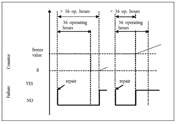
5.ILLUSTRATION OF THE ACTIVATION AND DEACTIVATION AND COUNTER MECHANISMSU.K.
5.1.This Section illustrates the activation and deactivation and counter mechanisms for some typical cases. The figures and descriptions given in Sections 4.2, 4.3 and 4.4 are provided solely for the purposes of illustration in this Annex and should not be referenced as examples of either the requirements of this Regulation or as definitive statements of the processes involved. For simplification purposes, for example, the fact that the warning system will also be active when the inducement system is active has not been mentioned in the illustrations given.U.K.
5.2.Figure 2 illustrates the operation of the activation and deactivation mechanisms when monitoring the reagent availability for five cases:U.K.
(a)
use case 1: the driver continues operating the vehicle in spite of the warning until vehicle operation is disabled;
(b)
repair case 1 (‘adequate’ refilling): the driver refills the reagent tank so that a level above the 10 % threshold is reached. Warning and inducement are de-activated;
(c)
repair cases 2 and 3 (‘inadequate’ refilling): The warning system is activated. The level of warning depends on the amount of available reagent;
(d)
repair case 4 (‘very inadequate’ refilling): The low-level inducement is activated immediately.
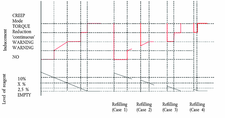
5.3.Figure 3 illustrates three cases of wrong urea quality:U.K.
(a)
use case 1: the driver continues operating the vehicle in spite of the warning until vehicle operation is disabled;
(b)
repair case 1 (‘bad’ or ‘dishonest’ repair): after disablement of the vehicle, the driver changes the quality of the reagent, but, soon after, changes it again for a poor quality one. The inducement system is immediately reactivated and vehicle operation is disabled after 2 engine operating hours;
(c)
repair case 2 (‘good’ repair): after disablement of the vehicle, the driver rectifies the quality of the reagent. However, some time afterwards, he refills again with a poor quality reagent. The warning, inducement, and counting processes restart from zero.

5.4.Figure 4 illustrates three cases of failure of the urea dosing system. This figure also illustrates the process that applies in the case of the monitoring failures described in Section 9.U.K.
(a)
Use case 1: the driver continues operating the vehicle in spite of the warning until vehicle operation is disabled.
(b)
Repair case 1 (‘good’ repair): after disablement of the vehicle, the driver repairs the dosing system. However, some time afterwards, the dosing system fails again. The warning, inducement, and counting processes restart from zero.
(c)
Repair case 2 (‘bad’ repair): during the low-level inducement time (torque reduction), the driver repairs the dosing system. Soon after, however, the dosing system fails again. The low-level inducement system is immediately reactivated and the counter restarts from the value it had at the time of repair.

Appendix 3
Low-level inducement torque reduction scheme U.K.
This diagram illustrates the provisions of Section 5.3 on torque reduction.
Appendix 4
Demonstration of correct installation on a vehicle in the case of engines EC type-approved as a separate technical unit U.K.
This Appendix applies when the vehicle manufacturer requests EC type-approval of a vehicle with an approved engine with regard to emissions and access to vehicle repair and maintenance information in accordance with this Regulation and Regulation (EC) No 595/2009.
In this case, and in addition to the installation requirements of Annex I, a demonstration of the correct installation is required. This demonstration shall be performed by the presentation to the approval authority of a technical case using evidence such as engineering drawings, functional analyses, and the results of previous tests.
Where appropriate, and if the manufacturer chooses, the evidence presented may include installations of systems or components on real or simulated vehicles, provided that the manufacturer can present evidence that the presented installation properly represents the standard that will be achieved in production.
The demonstration shall address the conformity of the following elements to the requirements of this Annex:
(a)
the installation on board the vehicle as regards its compatibility with the engine system (hardware, software and communication);
(b)
the warning and inducement systems (for example, pictograms, activation schemes, etc.);
(c)
the reagent tank and the elements (for example, sensors) mounted on the vehicle for the purpose of complying with this Annex.
Correct activation of the warning and inducement systems, and of the information storage and on-board and off-board communication systems, may be checked. No check of these systems shall require the dismounting of the engine system or components, nor shall it generate unnecessary testing burden by requiring processes such as changing of the urea quality or running of the vehicle or engine for long periods of time. In order to minimise the burden upon the vehicle manufacturer, electric disconnections and simulation of counters with high operating hours shall be selected as checks on these systems if possible.
Appendix 5
Access to ‘NOx control information’ U.K.
1.This Appendix describes the specifications permitting access to information required in order to check the status of the vehicle with regard to the correct operation of the NOx control system (NOx control information).U.K.
2.ACCESS METHODSU.K.
2.1.The ‘NOx control information’ shall be provided only in accordance with the standard or standards used in association with the retrieval of engine system information from the OBD system.U.K.
2.2.Access to the ‘NOx control information’ shall not be dependent on any access code or other device or method obtainable only from the manufacturer or the manufacturer’s suppliers. Interpretation of that information shall not require any specialised or unique decoding information, unless that information is publicly available.U.K.
2.3.It shall be possible to retrieve all ‘NOx control information’ from the system using the access method that is used to retrieve OBD information in accordance with Annex X.U.K.
2.4.It shall be possible to retrieve all ‘NOx control information’ information from the system using the test equipment that is used to retrieve OBD information in accordance with Annex X.U.K.
2.5.The ‘NOx control information’ shall be available through ‘read-only’ access (that is, it shall not be possible to clear, reset, erase, or modify any of the data).U.K.
3.INFORMATION CONTENTU.K.
3.1.The ‘NOx control information’ shall contain at least the following information:U.K.
(a)
the VIN (vehicle identification number);
(b)
the status of the warning system (active; non-active);
(c)
the status of the low-level inducement system (active; enabled; non-active);
(d)
the status of the severe inducement system (active; enabled; non-active);
(e)
[F1number of warm-up cycles and number of engine operating hours since recorded ‘NO x control information’ was cleared due to service or repair;]
(f)
the types of the counters relevant to this Annex (reagent quality, reagent consumption, dosing system, EGR valve, monitoring system) and the number of engine operating hours indicated by each of the these counters; in the case of multiple counters being used, the value to be considered for the purposes of the ‘NOx control information’ is the value of each of the counters relative to the failure under consideration having the highest value;
(g)
the DTCs associated with the malfunctions relevant to this Annex and their status (‘potential’, ‘confirmed and active’, etc.).
Appendix 6
Demonstration of the minimum acceptable reagent concentration CDmin U.K.
1.The manufacturer shall demonstrate the correct value of CDmin during type-approval by performing the hot part of the WHTC cycle, in accordance with the provisions of Annex 4B to UN/ECE Regulation No 49, using a reagent with the concentration CDmin.U.K.
2.The test shall follow the appropriate pre-conditioning cycle, permitting a closed loop NOx control system to perform adaptation to the quality of the reagent with the concentration CDmin.U.K.
3.The pollutant emissions resulting from this test shall be lower than the emission limits specified in Sections 7.1.1 and 7.1.1.1 of this Annex.U.K.
ANNEX XIVU.K. MEASUREMENT OF NET ENGINE POWER
1.INTRODUCTIONU.K.
1.1.This Annex sets out requirements for measuring net engine power.U.K.
2.GENERALU.K.
2.1.The general specifications for conducting the tests and interpreting the results shall be those set out in Section 5 of UN/ECE Regulation 85 with the exceptions specified in this Annex.U.K.
2.1.1.Measurement of net power according to this Annex shall be performed on all members of an engine family.U.K.
2.2. Test fuel U.K.
2.2.1.For positive-ignition engines fuelled with petrol or E85 Section 5.2.3.1 of UN/ECE Regulation No 85 shall be understood as follows:U.K.
The fuel used shall be the one available on the market. In any case of dispute the fuel shall be the appropriate reference fuel specified in Annex IX to Regulation (EU) No 582/2011. Instead of above mentioned reference fuels, the reference fuels defined by the Coordinating European Council for the Development of performance Tests for Lubricants and Engine Fuels (hereinafter ‘CEC’), for petrol fuelled engines in CEC documents RF-01-A-84 and RF-01-A-85 may be used.
2.2.2.For positive-ignition engines fuelled with LPG:U.K.
2.2.2.1
In the case of an engine with self-adapting fuelling Section 5.2.3.2.1 of UN/ECE Regulation No 85 shall be understood as follows:
The fuel used shall be the one available on the market. In any case of dispute the fuel shall be the appropriate reference fuel specified in Annex IX to Regulation (EU) No 582/2011. Instead of above mentioned reference fuels, the reference fuels specified in Annex 8 to this Regulation may be used.
2.2.2.2.
In the case of an engine without self-adaptive fuelling Section 5.2.3.2.2 of UN/ECE Regulation No 85 shall be understood as follows:
The fuel used shall be the reference fuel specified in Annex IX to Regulation (EU) No 582/2011 or the reference fuels specified in Annex 8 to this Regulation may be used with the lowest C3- content, or
2.2.3.For positive-ignition engines fuelled with natural gas:U.K.
2.2.3.1.
In the case of an engine with self-adaptive fuelling Section 5.2.3.3.1 of UN/ECE Regulation No 85 shall be understood as follows:
The fuel used shall be the one available on the market. In any case of dispute the fuel shall be the appropriate reference fuel specified in Annex IX to Regulation (EU) No 582/2011. Instead of above mentioned reference fuels, the reference fuels specified in Annex 8 to this Regulation may be used.
2.2.3.2.
In the case of an engine without self-adaptive fuelling Section 5.2.3.3.2 of UN/ECE Regulation No 85 shall be understood as follows:
The fuel used shall be the one available on the market with a Wobbe index at least 52,6 MJm-3 (20 °C, 101,3 kPa). In case of dispute the fuel used shall be the reference fuel GR specified in Annex IX to Regulation (EU) No 582/2011.
2.2.3.3.
In the case of an engine labelled for a specific range of fuels Section 5.2.3.3.3 of UN/ECE Regulation No 85 shall be understood as follows:
The fuel used shall be the one available on the market with a Wobbe index at least 52,6 MJm-3 (20 °C, 101,3 kPa) if the engine is labelled for the H-range of gases, or at least 47,2 MJm-3 (20 °C, 101,3 kPa) if the engine is labelled for the L-range of gases. In case of dispute the fuel used shall be the reference fuel GR specified in Annex IX to Regulation (EU) No 582/2011 if the engine is labelled for the H-range of gases, or the reference fuel G23 if the engine is labelled for the L-range of gases, i.e. the fuel with the highest Wobbe index for the relevant range, or
2.2.4.For compression-ignition engines Section 5.2.3.4 of UN/ECE Regulation 85 shall read:U.K.
The fuel used shall be the one available on the market. In any case of dispute the fuel shall be the appropriate reference fuel specified in Annex IX to Regulation (EU) No 582/2011. Instead of above mentioned reference fuels, the reference fuel defined by the CEC, for compression-ignition engines in CEC document RF-03-A-84 may be used.
2.3. Engine-driven equipment U.K.
The requirements on engine-driven equipment differ between UN/ECE Regulation No 85 (power testing) and UN/ECE Regulation No 49 (emissions testing).
2.3.1.For the purpose of measuring the net engine power the provisions regarding test conditions and auxiliaries as specified in Annex 5 to UN/ECE Regulation No 85 shall apply.U.K.
2.3.2.For the purpose of emissions testing following the procedures in Annex III to this Regulation the provisions regarding engine power as specified in Section 6 of Annex 4B and Appendix 7 to UN/ECE Regulation No 49 shall apply.U.K.
ANNEX XVU.K. AMENDMENTS TO REGULATION (EC) No 595/2009
Annex I to Regulation (EC) No 595/2009 is replaced by the following:
‘ANNEX IU.K.
Euro VI Emission Limits
| a The admissible level of NO2 component in the NOx limit value may be defined at a later stage. | ||||||||
| b A new measurement procedure shall be introduced before 31 December 2012. | ||||||||
| c A particle number limit shall be introduced before 31 December 2012. | ||||||||
| PI = Positive Ignition. CI = Compression Ignition.’ | ||||||||
| Limit values | ||||||||
|---|---|---|---|---|---|---|---|---|
| CO(mg/kWh) | THC(mg/kWh) | NMHC(mg/kWh) | CH4(mg/kWh) | NOx a(mg/kWh) | NH3(ppm) | PM mass(mg/kWh) | PMb number(#/kWh) | |
| WHSC (CI) | 1 500 | 130 | 400 | 10 | 10 | 8,0 × 10¹¹ | ||
| WHTC (CI) | 4 000 | 160 | 460 | 10 | 10 | 6,0 × 10¹¹ | ||
| WHTC (PI) | 4 000 | 160 | 500 | 460 | 10 | 10 | c | |
ANNEX XVIU.K. AMENDMENTS TO DIRECTIVE 2007/46/EC
Directive 2007/46/EC is amended as follows:
(1)
Annex I is amended as follows:
(a)
the following point 3.2.1.11 is inserted:
‘3.2.1.11.(Euro VI only) Manufacturer references of the Documentation package required by Articles 5, 7 and 9 of Regulation (EU) No 582/2011 enabling the approval authority to evaluate the emission control strategies and the Systems on-board the engine to ensure the correct operation of NOx control measures’;
(b)
point 3.2.2.2 is replaced by the following:
‘3.2.2.2.Heavy duty vehicles Diesel/Petrol/LPG/NG-H/NG-L/NG-HL/Ethanol (ED95)/Ethanol (E85) (1) (6)’;
(c)
the following point 3.2.2.2.1 is inserted:
‘3.2.2.2.1.(Euro VI only) Fuels compatible with use by the engine declared by the manufacturer in accordance with Section 1.1.2 of Annex I to Regulation (EU) No 582/2011 (as applicable)’;
(d)
the following point 3.2.8.3.3 is inserted:
‘3.2.8.3.3.(Euro VI only) Actual Intake system depression at rated engine speed and at 100 % load on the vehicle: kPa’;
(e)
the following point 3.2.9.2.1 is inserted:
‘3.2.9.2.1.(Euro VI only) Description and/or drawing of the elements of the exhaust system that are not part of the engine system’;
(f)
the following point 3.2.9.3.1 is inserted:
‘3.2.9.3.1.(Euro VI only) Actual exhaust back pressure at rated engine speed and at 100 % load on the vehicle (compression-ignition engines only): … kPa’;
(g)
the following point 3.2.9.7.1 is inserted:
‘3.2.9.7.1.(Euro VI only) Acceptable Exhaust system volume: … dm3’;
(h)
the following point 3.2.12.1.1 is inserted:
‘3.2.12.1.1.(Euro VI only) Device for recycling crankcase gases: yes/no (2)
If yes, description and drawings:
If no, compliance with Annex V to Regulation (EU) No 582/2011 required’;
(i)
in point 3.2.12.2.6.8.1 the following wording is added;
‘(not applicable to Euro VI)’;
(j)
the following point 3.2.12.2.6.8.1.1 is inserted:
‘3.2.12.2.6.8.1.1.(Euro VI only) Number of WHTC test cycles without regeneration (n):’;
(k)
in points 3.2.12.2.6.8.2 the following wording is added:
‘(not applicable to Euro VI)’;
(l)
the following point 3.2.12.2.6.8.2.1 is inserted:
‘3.2.12.2.6.8.2.1.(Euro VI only) Number of WHTC test cycles with regeneration (nR):’;
(m)
the following points 3.2.12.2.6.9 and 3.2.12.2.6.9.1 are inserted:
‘3.2.12.2.6.9.Other systems: yes/no (1)
3.2.12.2.6.9.1.Description and operation’;
(n)
the following points 3.2.12.2.7.0.1 to 3.2.12.2.7.0.8 are inserted:
‘3.2.12.2.7.0.1.
(Euro VI only) Number of OBD engine families within the engine family
3.2.12.2.7.0.2.
List of the OBD engine families (when applicable)
3.2.12.2.7.0.3.
Number of the OBD engine family the parent engine / the engine member belongs to:
3.2.12.2.7.0.4.
Manufacturer references of the OBD-Documentation required by Article 5(4)(c) and Article 9(4) of Regulation (EU) No 582/2011 and specified in Annex X to that Regulation for the purpose of approving the OBD system
3.2.12.2.7.0.5.
When appropriate, manufacturer reference of the Documentation for installing in a vehicle an OBD equipped engine system
3.2.12.2.7.0.6.
When appropriate, manufacturer reference of the documentation package related to the installation on the vehicle of the OBD system of an approved engine
3.2.12.2.7.0.7.
Written description and/or drawing of the MI (6)
3.2.12.2.7.0.8.
Written description and/or drawing of the OBD off-board communication interface (6)’;
(o)
the following points 3.2.12.2.7.6.5, 3.2.12.2.7.7 and 3.2.12.2.7.7.1 are inserted:
‘3.2.12.2.7.6.5.(Euro VI only) OBD Communication protocol standard: (4)
3.2.12.2.7.7.(Euro VI only) Manufacturer reference of the OBD related information required by of Article 5(4)(d) and Article 9(4) of Regulation (EU) No 582/2011 for the purpose of complying with the provisions on access to vehicle OBD and vehicle Repair and Maintenance Information, or
3.2.12.2.7.7.1.As an alternative to a manufacturer reference provided in Section 3.2.12.2.7.7 reference of the attachment to the information document set out in Appendix 4 of Annex I to Regulation (EU) No 582/2011 that contains the following table, once completed according to the given example:
Component — Fault code — Monitoring strategy — Fault detection criteria — MI activation criteria — Secondary parameters — Preconditioning — Demonstration test
Catalyst – P0420 — Oxygen sensor 1 and 2 signals — Difference between sensor 1 and sensor 2 signals — 3rd cycle — Engine speed, engine load, A/F mode, catalyst temperature — Two Type 1 cycles — Type 1’;
(p)
the following points 3.2.12.2.8.1 to 3.2.12.2.8.8.3 are inserted:
‘3.2.12.2.8.1.
(Euro VI only) Systems to ensure the correct operation of NOx control measures
3.2.12.2.8.2.
(Euro VI only) Engine with permanent deactivation of the driver inducement, for use by the rescue services or in vehicles specified in Article 2(3)(b) of this Directive: yes/no
3.2.12.2.8.3.
(Euro VI only) Number of OBD engine families within the engine family considered when ensuring the correct operation of NOx control measures
3.2.12.2.8.4.
(Euro VI only) List of the OBD engine families (when applicable)
3.2.12.2.8.5.
(Euro VI only) Number of the OBD engine family the parent engine / the engine member belongs to
3.2.12.2.8.6.
(Euro VI only) Lowest concentration of the active ingredient present in the reagent that does not activate the warning system (CDmin): (% vol.)
3.2.12.2.8.7.
(Euro VI only) When appropriate, manufacturer reference of the Documentation for installing in a vehicle the systems to ensure the correct operation of NOx control measures
3.2.12.2.8.8.
Components on-board the vehicle of the systems ensuring the correct operation of NOx control measures
3.2.12.2.8.8.1.
Activation of the creep mode:
“disable after restart” / “disable after fuelling” / “disable after parking” (7)
3.2.12.2.8.8.2.
When appropriate, manufacturer reference of the documentation package related to the installation on the vehicle of the system ensuring the correct operation of NOx control measures of an approved engine
3.2.12.2.8.8.3.
Written description and/or drawing of the warning signal (6)’;
(q)
the following points 3.2.17.8.1.0.1 and 3.2.17.8.1.0.2 are inserted:
‘3.2.17.8.1.0.1.
(Euro VI only) Self adaptive feature? Yes/No (1)
3.2.17.8.1.0.2.
(Euro VI only) Calibration for a specific gas composition NG-H/NG-L/NG-HL (1)
Transformation for a specific gas composition NG-Ht/NG-Lt/NG-HLt (1)’;
(r)
The following points 3.5.4 to 3.5.5.2 are inserted:
‘3.5.4.
CO2 emissions for heavy duty engines (Euro VI only)
3.5.4.1.
CO2 mass emissions WHSC test … g/kWh
3.5.4.2.
CO2 mass emissions WHTC test: … g/kWh
3.5.5.
Fuel consumption for heavy duty engines (Euro VI only)
3.5.5.1.
Fuel consumption WHSC test: … g/kWh
3.5.5.2.
Fuel consumption WHTC test: … g/kWh’;
(2)
Part I, Section A of Annex III is amended as follows:
(a)
the following point 3.2.1.11 is inserted:
‘3.2.1.11.(Euro VI only) Manufacturer references of the Documentation package required by Articles 5, 7 and 9 of Regulation (EU) No 582/2011 enabling the approval authority to evaluate the emission control strategies and the systems on-board the engine to ensure the correct operation of NOx control measures’;
(b)
point 3.2.2.2 is replaced by the following:
‘3.2.2.2Heavy duty vehicles Diesel/Petrol/LPG/NG-H/NG-L/NG-HL/Ethanol (ED95)/Ethanol (E85) (1) (6)’;
(c)
the following point 3.2.2.2.1 is inserted:
‘3.2.2.2.1.(Euro VI only) Fuels compatible with use by the engine declared by the manufacturer in accordance with Section 1.1.3 of Annex I to Regulation (EU) No 582/2011 (as applicable)’;
(d)
the following point 3.2.8.3.3 is inserted:
‘3.2.8.3.3.(Euro VI only) Actual Intake system depression at rated engine speed and at 100 % load on the vehicle: kPa’;
(e)
the following point 3.2.9.2.1 is inserted:
‘3.2.9.2.1.(Euro VI only) Description and/or drawing of the elements of the exhaust system that are not part of the engine system’;
(f)
the following point 3.2.9.3.1 is inserted:
‘3.2.9.3.1.(Euro VI only) Actual exhaust back pressure at rated engine speed and at 100 % load on the vehicle (compression-ignition engines only): … kPa’;
(g)
the following point 3.2.9.7.1 is inserted:
‘3.2.9.7.1.(Euro VI only) Acceptable Exhaust system volume: … dm3’;
(h)
the following point 3.2.12.1.1 is inserted:
‘3.2.12.1.1.(Euro VI only) Device for recycling crankcase gases: yes/no (2)
If yes, description and drawings:
If no, compliance with Annex V to Regulation (EU) No 582/2011 required’;
(i)
the following points 3.2.12.2.6.9 and 3.2.12.2.6.9.1 are inserted:
‘3.2.12.2.6.9.Other systems: yes/no (1)
3.2.12.2.6.9.1.Description and operation’;
(j)
the following points 3.2.12.2.7.0.1 to 3.2.12.2.7.0.8 are inserted:
‘3.2.12.2.7.0.1.
(Euro VI only) Number of OBD engine families within the engine family
3.2.12.2.7.0.2.
(Euro VI only) List of the OBD engine families (when applicable)
3.2.12.2.7.0.3.
(Euro VI only) Number of the OBD engine family the parent engine / the engine member belongs to:
3.2.12.2.7.0.4.
(Euro VI only) Manufacturer references of the OBD-Documentation required by Article 5(4)(c) and Article 9(4) of Regulation (EU) No 582/2011 and specified in Annex X to that Regulation for the purpose of approving the OBD system
3.2.12.2.7.0.5.
(Euro VI only) When appropriate, manufacturer reference of the Documentation for installing in a vehicle an OBD equipped engine system
3.2.12.2.7.0.6.
(Euro VI only) When appropriate, manufacturer reference of the documentation package related to the installation on the vehicle of the OBD system of an approved engine
3.2.12.2.7.0.7.
(Euro VI only) Written description and/or drawing of the MI (6)
3.2.12.2.7.0.8.
(Euro VI only) Written description and/or drawing of the OBD off-board communication interface (6)’;
(k)
the following points 3.2.12.2.7.6.5, 3.2.12.2.7.7 and 3.2.12.2.7.7.1 are inserted:
‘3.2.12.2.7.6.5.(Euro VI only) OBD Communication protocol standard: (4)
3.2.12.2.7.7.(Euro VI only) Manufacturer reference of the OBD related information required by of Article 5(4)(d) and Article 9(4) of Regulation (EU) No 582/2011 for the purpose of complying with the provisions on access to vehicle OBD and vehicle Repair and Maintenance Information, or
3.2.12.2.7.7.1.As an alternative to a manufacturer reference provided in Section 3.2.12.2.7.7 reference of the attachment to the information document set out in Appendix 4 of Annex III to Regulation (EU) No 582/2011 that contains the following table, once completed according to the given example:
Component — Fault code — Monitoring strategy — Fault detection criteria — MI activation criteria — Secondary parameters — Preconditioning — Demonstration test
Catalyst — P0420 — Oxygen sensor 1 and 2 signals — Difference between sensor 1 and sensor 2 signals — 3rd cycle — Engine speed, engine load, A/F mode, catalyst temperature — Two Type 1 cycles — Type 1’;
(l)
the following points 3.2.12.2.8.1 to 3.2.12.2.8.8.3 are inserted:
‘3.2.12.2.8.1.
(Euro VI only) Systems to ensure the correct operation of NOx control measures
3.2.12.2.8.2.
(Euro VI only) Engine with permanent deactivation of the driver inducement, for use by the rescue services or in vehicles specified in Article 2(3)(b) of this Directive: yes/no
3.2.12.2.8.3.
(Euro VI only) Number of OBD engine families within the engine family considered when ensuring the correct operation of NOx control measures
3.2.12.2.8.4.
(Euro VI only) List of the OBD engine families (when applicable)
3.2.12.2.8.5.
(Euro VI only) Number of the OBD engine family the parent engine / the engine member belongs to
3.2.12.2.8.6.
(Euro VI only) Lowest concentration of the active ingredient present in the reagent that does not activate the warning system (CDmin): (% vol.)
3.2.12.2.8.7.
(Euro VI only) When appropriate, manufacturer reference of the Documentation for installing in a vehicle the systems to ensure the correct operation of NOx control measures
3.2.12.2.8.8.
Components on-board the vehicle of the systems ensuring the correct operation of NOx control measures
3.2.12.2.8.8.1.
Activation of the creep mode:
“disable after restart” / “disable after fuelling” / “disable after parking” (7)
3.2.12.2.8.8.2.
When appropriate, manufacturer reference of the documentation package related to the installation on the vehicle of the system ensuring the correct operation of NOx control measures of an approved engine
3.2.12.2.8.8.3.
Written description and/or drawing of the warning signal (6)’;
(m)
the following points 3.2.17.8.1.0.1 and 3.2.17.8.1.0.2 are inserted:
‘3.2.17.8.1.0.1.
(Euro VI only) Self adaptive feature? Yes/No (1)
3.2.17.8.1.0.2.
(Euro VI only) Calibration for a specific gas composition NG-H/NG-L/NG-HL (1)
Transformation for a specific gas composition NG-Ht/NG-Lt/NG-HLt (1)’;
(n)
the following points 3.5.4 to 3.5.5.2 are inserted:
‘3.5.4.
(Euro VI only) CO2 emissions for heavy duty engines
3.5.4.1.
(Euro VI only) CO2 mass emissions WHSC test: … g/kWh
3.5.4.2.
(Euro VI only) CO2 mass emissions WHTC test: … g/kWh
3.5.5.
(Euro VI only) Fuel consumption for heavy duty engines
3.5.5.1.
(Euro VI only) Fuel consumption WHSC test: … g/kWh
3.5.5.2.
(Euro VI only) Fuel consumption WHTC test: … g/kWh’.
[F3ANNEX XVII U.K. ACCESS TO VEHICLE OBD AND VEHICLE REPAIR AND MAINTENANCE INFORMATION
1. INTRODUCTION U.K.
1.1. This Annex lays down technical requirements for the accessibility of vehicle OBD and vehicle repair and maintenance information. U.K.
2. REQUIREMENTS U.K.
2.1. Vehicle OBD and vehicle repair and maintenance information available through websites shall follow the common standard referred to in Article 6(1) of Regulation (EC) No 595/2009. Until this standard is adopted, manufacturers shall provide vehicle OBD and vehicle repair and maintenance information in a standardised manner which is non-discriminatory compared to the provisions given or access granted to authorised dealers and repairers. U.K.
Those requiring the right to duplicate or republish the information shall negotiate directly with the manufacturer concerned. Information for training material shall also be available, but may be presented through other media than websites.
Information on all parts of the vehicle, with which the vehicle, as identified by the vehicle identification number (VIN) and any additional criteria such as wheelbase, engine output, trim level or options, is equipped by the vehicle manufacturer and which can be replaced by spare parts offered by the vehicle manufacturer to its authorised repairers or dealers or third parties by means of reference to original equipment (OE) parts number, shall be made available in a database which is easily accessible to independent operators.
This database shall comprise the VIN, OE parts numbers, OE naming of the parts, validity attributes (valid-from and valid-to dates), fitting attributes and, where applicable, structuring characteristics.
The information on the database shall be regularly updated. The updates shall include in particular all modifications to individual vehicles after their production if this information is available to authorised dealers.
2.2. Access to vehicle security features used by authorised dealers and repair shops shall be made available to independent operators under protection of security technology in accordance with the following requirements: U.K.
(a)
data shall be exchanged ensuring confidentiality, integrity and protection against replay;
(b)
the standard https//ssl-tls (RFC4346) shall be used;
(c)
security certificates in accordance with ISO 20828 shall be used for mutual authentication of independent operators and manufacturers;
(d)
the independent operator’s private key shall be protected by secure hardware.
The Forum on Access to Vehicle Information referred to in Article 2h shall specify the parameters for fulfilling these requirements in accordance with the state of the art. The independent operator shall be approved and authorised for this purpose on the basis of documents demonstrating that he pursues a legitimate business activity and has not been convicted of any criminal activity.
2.3. Reprogramming of control units shall be conducted in accordance with either ISO 22900-2 or SAE J2534 or TMC RP1210B using non-proprietary hardware. Ethernet, serial cable or local area network (LAN) interface and alternative media like compact disc (CD), digital versatile disc (DVD) or solid state memory device for infotainment systems (e.g. navigation systems, telephone) may also be used, but on the condition that no proprietary communication software (e.g. drivers or plug-ins) and hardware is required. For the validation of the compatibility of the manufacturer-specific application and the vehicle communication interfaces (VCI) complying to ISO 22900-2 or SAE J2534 or TMC RP1210B, the manufacturer shall offer either a validation of independently developed VCIs or the information, and loan of any special hardware, required for a VCI manufacturer to conduct such validation himself. The conditions of Article 2f(1) shall apply to fees for such validation or information and hardware. U.K.
2.4. The requirements of section 2.3 shall not apply in the case of reprogramming of speed limitation devices and recording equipment. U.K.
2.5. All emission-related DTCs shall be consistent with Annex X. U.K.
2.6. For access to any vehicle OBD and vehicle repair and maintenance information other than that relating to secure areas of the vehicle, registration requirements for use of the manufacturer’s website by an independent operator shall require only such information as is necessary to confirm how payment for the information is to be made. For information concerning access to secure areas of the vehicle, the independent operator shall present a certificate in accordance with ISO 20828 to identify himself and the organisation to which he belongs and the manufacturer shall respond with his own certificate in accordance with ISO 20828 to confirm to the independent operator that he is accessing a legitimate site of the intended manufacturer. Both parties shall keep a log of any such transactions indicating the vehicles and changes made to them under this provision. U.K.
2.7. Manufacturers shall indicate in their repair information websites the type-approval number by model. U.K.
2.8. If requested by the manufacturer, for vehicles of category M 1 , M 2 , N 1 and N 2 with a maximum permissible mass not exceeding 7,5 tonnes and M 3 Class I, Class II and Class A and Class B, as defined in Annex I to Directive 2001/85/EC, with a permissible mass not exceeding 7,5 tonnes, compliance with the requirements of Appendix 5 to Annex I and Annex XIV to Regulation (EC) No 692/2008 shall be considered equivalent to the compliance with this Annex. U.K.
2.9. The approval authority shall inform the Commission of the circumstances of each type-approval granted under Section 2.8. U.K.
Appendix 1
Manufacturer’s Certificate on Access to Vehicle OBD and Vehicle Repair and Maintenance Information U.K.
(Manufacturer): …
(Address of the manufacturer): …
Certifies that
it provides access to vehicle OBD and vehicle repair and maintenance information in compliance with the provisions of:
Article 6 of Regulation (EC) No 595/2009 and Article 2a of Regulation (EU) No 582/2011,
Article 4(6) of Regulation (EU) No 582/2011,
Annex I, Appendix 4, Section 16 of Regulation (EU) No 582/2011,
Annex X, Section 2.1 of Regulation (EU) No 582/2011,
Annex XVII of Regulation (EU) No 582/2011,
with respect to the types of vehicle, engine, pollution control device listed in attachment to this Certificate.
The following derogations are applied: Customer adaptations (11) — Small volume (11) — Carry-over systems (11) .
The principal website address through which the relevant information may be accessed and which is hereby certified to be in compliance with the above provisions are listed in an attachment to this Certificate along with the contact details of the responsible manufacturer’s representative whose signature is below.
Where applicable: The manufacturer hereby also certifies that it has complied with the obligation provided for in Article 3(1a) of Regulation (EU) No 582/2011 to provide the relevant information for previous approvals of these vehicle types no later than six months after the date of type-approval.
Done at [Place]
On [Date]
[Signature] [Position]
Annexes:
Website addresses,
Contact details.
ANNEX I to Manufacturer’s Certificate on Access to Vehicle OBD and Vehicle Repair and Maintenance Information
Website addresses referred to by this Certificate:
ANNEX II to Manufacturer’s Certificate on Access to Vehicle OBD and Vehicle Repair and Maintenance Information
Contact details of the manufacturer’s representative referred to by this Certificate:
Appendix 2
Vehicle OBD information U.K.
1. The information required in this Appendix shall be provided by the vehicle manufacturer for the purposes of enabling the manufacture of OBD-compatible replacement or service parts and diagnostic tools and test equipment. U.K.
2. Upon request, the following information shall be made available to any interested component, diagnostic tools or test equipment manufacturer, on a non-discriminatory basis: U.K.
A description of the type and number of the preconditioning cycles used for the original type-approval of the vehicle.
A description of the type of the OBD demonstration cycle used for the original type-approval of the vehicle for the component monitored by the OBD system.
A comprehensive document describing all sensed components with the strategy for fault detection and MI activation (fixed number of driving cycles or statistical method), including a list of relevant secondary sensed parameters for each component monitored by the OBD system and a list of all OBD output codes and format used (with an explanation of each code and format) associated with individual emission-related power-train components and individual non-emission related components, where monitoring of the component is used to determine MI activation. In particular, in the case of vehicle types that use a communication link in accordance with ISO 15765-4 ‘ Road vehicles — Diagnostics on controller area network (CAN) — Part 4: Requirements for emissions-related systems ’ , a comprehensive explanation for the data given in service $ 05 Test ID $ 21 to FF and the data given in service $ 06, and a comprehensive explanation for the data given in service $ 06 Test ID $ 00 to FF, for each OBD monitor ID supported, shall be provided.
In case other communication protocols standards are used, equivalent comprehensive explanation shall be provided.
This information may be provided in the form of a table, as follows:
Component | Fault code | Monitoring strategy | Fault detection criteria | MI activation criteria | Secondary parameters | Preconditioning | Demonstration test |
Catalyst | P0420 | Oxygen sensor 1 and 2 signals | Difference between sensor 1 and sensor 2 signals | 3rd cycle | Engine speed, engine load, A/F mode, catalyst temperature | Two Type 1 cycles | Type 1 |
3. Information required for the manufacture of diagnostic tools U.K.
In order to facilitate the provision of generic diagnostic tools for multi-make repairers, vehicle manufacturers shall make available the information referred to in points 3.1, 3.2 and 3.3 through their repair information websites. That information shall include all diagnostic tool functions and all the links to repair information and troubleshooting instructions. The access to the information may be subject to the payment of a reasonable fee.
3.1. Communication protocol information U.K.
The following information shall be required indexed against vehicle make, model and variant, or other workable definition such as VIN or vehicle and systems identification:
(a)
Any additional protocol information system necessary to enable complete diagnostics in addition to the standards prescribed in Point 4.7.3 of Annex 9B to UN/ECE Regulation No 49, including any additional hardware or software protocol information, parameter identification, transfer functions, ‘ keep alive ’ requirements, or error conditions.
(b)
Details of how to obtain and interpret all fault codes which are not in accordance with the standards prescribed in Point 4.7.3 of Annex 9B to UN/ECE Regulation No 49.
(c)
A list of all available live data parameters, including scaling and access information.
(d)
A list of all available functional tests, including device activation or control and the means to implement them.
(e)
Details of how to obtain all component and status information, time stamps, pending DTC and freeze frames.
(f)
Resetting adaptive learning parameters, variant coding and replacement component setup, and customer preferences.
(g)
ECU identification and variant coding.
(h)
Details of how to reset service lights.
(i)
Location of diagnostic connector and connector details.
(j)
Engine code identification.
3.2. Test and diagnosis of OBD monitored components U.K.
The following information shall be required:
(a)
A description of tests to confirm its functionality, at the component or in the harness.
(b)
Test procedure including test parameters and component information.
(c)
Connection details including minimum and maximum input and output and driving and loading values.
(d)
Values expected under certain driving conditions including idling.
(e)
Electrical values for the component in its static and dynamic states.
(f)
Failure mode values for each of the above scenarios.
(g)
Failure mode diagnostic sequences including fault trees and guided diagnostics elimination.
3.3. Data required to perform the repair U.K.
The following information shall be required:
(a)
ECU and component initialisation (in the event of replacements being fitted).
(b)
Initialisation of new or replacement ECU’s where relevant using pass-through (re-) programming techniques.
Appendix 3
List of carry-over systems covered by Article 2e
(3)
Directive 2001/85/EC of the European Parliament and of the Council of 20 November 2001 relating to special provisions for vehicles used for the carriage of passengers comprising more than eight seats in addition to the driver’s seat, and amending Directives 70/156/EEC and 97/27/EC (OJ L 42, 13.2.2002, p. 1).
(4)
[F3Vehicle or vehicles in the case of a secondary engine.]
(6)
The failure classification rules are specified in Annex 9B to UN/ECE Regulation No 49.
(7)
This Section is subject to review after the end of the phase-in period specified in Article 4(7).
(8)
Delete where not applicable.
(9)
Delete where not applicable.
(10)
If the means of identification of type contains characters not relevant to describe the vehicle, component or separate technical unit types covered by this type-approval certificate such characters shall be represented in the document by the symbol: ‘?’ (e.g. ABC??123??).
(11)
[F3Delete where not applicable.]
Textual Amendments
Options/Cymorth
Print Options
PrintThe Whole Regulation
PrintThe Annexes only
You have chosen to open the Whole Regulation
The Whole Regulation you have selected contains over 200 provisions and might take some time to download. You may also experience some issues with your browser, such as an alert box that a script is taking a long time to run.
Would you like to continue?
You have chosen to open Schedules only
Y Rhestrau you have selected contains over 200 provisions and might take some time to download. You may also experience some issues with your browser, such as an alert box that a script is taking a long time to run.
Would you like to continue?
Mae deddfwriaeth ar gael mewn fersiynau gwahanol:
Y Diweddaraf sydd Ar Gael (diwygiedig):Y fersiwn ddiweddaraf sydd ar gael o’r ddeddfwriaeth yn cynnwys newidiadau a wnaed gan ddeddfwriaeth ddilynol ac wedi eu gweithredu gan ein tîm golygyddol. Gellir gweld y newidiadau nad ydym wedi eu gweithredu i’r testun eto yn yr ardal ‘Newidiadau i Ddeddfwriaeth’.
Gwreiddiol (Fel y’i mabwysiadwyd gan yr UE): Mae'r wreiddiol version of the legislation as it stood when it was first adopted in the EU. No changes have been applied to the text.
Pwynt Penodol mewn Amser: This becomes available after navigating to view revised legislation as it stood at a certain point in time via Advanced Features > Show Timeline of Changes or via a point in time advanced search.
Gweler y wybodaeth ychwanegol ochr yn ochr â’r cynnwys
Rhychwant ddaearyddol: Indicates the geographical area that this provision applies to. For further information see ‘Frequently Asked Questions’.
Dangos Llinell Amser Newidiadau: See how this legislation has or could change over time. Turning this feature on will show extra navigation options to go to these specific points in time. Return to the latest available version by using the controls above in the What Version box.
Dewisiadau Agor
Dewisiadau gwahanol i agor deddfwriaeth er mwyn gweld rhagor o gynnwys ar y sgrin ar yr un pryd
Rhagor o Adnoddau
Gallwch wneud defnydd o ddogfennau atodol hanfodol a gwybodaeth ar gyfer yr eitem ddeddfwriaeth o’r tab hwn. Yn ddibynnol ar yr eitem ddeddfwriaeth sydd i’w gweld, gallai hyn gynnwys:
- y PDF print gwreiddiol y fel adopted version that was used for the EU Official Journal
- rhestr o newidiadau a wnaed gan a/neu yn effeithio ar yr eitem hon o ddeddfwriaeth
- pob fformat o’r holl ddogfennau cysylltiedig
- slipiau cywiro
- dolenni i ddeddfwriaeth gysylltiedig ac adnoddau gwybodaeth eraill
Llinell Amser Newidiadau
Mae’r llinell amser yma yn dangos y fersiynau gwahanol a gymerwyd o EUR-Lex yn ogystal ag unrhyw fersiynau dilynol a grëwyd ar ôl y diwrnod ymadael o ganlyniad i newidiadau a wnaed gan ddeddfwriaeth y Deyrnas Unedig.
Cymerir dyddiadau fersiynau’r UE o ddyddiadau’r dogfennau ar EUR-Lex ac efallai na fyddant yn cyfateb â’r adeg pan ddaeth y newidiadau i rym ar gyfer y ddogfen.
Ar gyfer unrhyw fersiynau a grëwyd ar ôl y diwrnod ymadael o ganlyniad i newidiadau a wnaed gan ddeddfwriaeth y Deyrnas Unedig, bydd y dyddiad yn cyd-fynd â’r dyddiad cynharaf y daeth y newid (e.e. ychwanegiad, diddymiad neu gyfnewidiad) a weithredwyd i rym. Am ragor o wybodaeth gweler ein canllaw i ddeddfwriaeth ddiwygiedig ar Ddeall Deddfwriaeth.
Rhagor o Adnoddau
Defnyddiwch y ddewislen hon i agor dogfennau hanfodol sy’n cyd-fynd â’r ddeddfwriaeth a gwybodaeth am yr eitem hon o ddeddfwriaeth. Gan ddibynnu ar yr eitem o ddeddfwriaeth sy’n cael ei gweld gall hyn gynnwys:
- y PDF print gwreiddiol y fel adopted fersiwn a ddefnyddiwyd am y copi print
- slipiau cywiro
liciwch ‘Gweld Mwy’ neu ddewis ‘Rhagor o Adnoddau’ am wybodaeth ychwanegol gan gynnwys
- rhestr o newidiadau a wnaed gan a/neu yn effeithio ar yr eitem hon o ddeddfwriaeth
- manylion rhoi grym a newid cyffredinol
- pob fformat o’r holl ddogfennau cysylltiedig
- dolenni i ddeddfwriaeth gysylltiedig ac adnoddau gwybodaeth eraill
 Mae’r holl gynnwys ar gael dan Drwydded Llywodraeth Agored v3.0 ac eithrio ble nodir yn wahanol. Yn ychwanegol mae’r safle hwn â chynnwys sy’n deillio o EUR-Lex, a ailddefnyddiwyd dan delerau Penderfyniad y Comisiwn 2011/833/EU ar ailddefnyddio dogfennau o sefydliadau’r UE. Am ragor o wybodaeth gweler ddatganiad cyhoeddus Swyddfa Gyhoeddiadau’r UE ar ailddefnyddio.