- Y Diweddaraf sydd Ar Gael (Diwygiedig)
- Gwreiddiol (Fel y’i mabwysiadwyd gan yr UE)
Commission Regulation (EU) 2017/2400Dangos y teitl llawn
Commission Regulation (EU) 2017/2400 of 12 December 2017 implementing Regulation (EC) No 595/2009 of the European Parliament and of the Council as regards the determination of the CO2 emissions and fuel consumption of heavy-duty vehicles and amending Directive 2007/46/EC of the European Parliament and of the Council and Commission Regulation (EU) No 582/2011 (Text with EEA relevance)
You are here:

Pa Fersiwn
Nodweddion Uwch
- Dangos Graddfa Ddaearyddol(e.e. Lloegr, Cymru, Yr Alban aca Gogledd Iwerddon)
- Dangos Llinell Amser Newidiadau
Rhagor o Adnoddau
PDF o Fersiynau Diwygiedig
- ddiwygiedig 01/09/20203.68 MB
- ddiwygiedig 01/03/20193.55 MB
Legislation originating from the EU
When the UK left the EU, legislation.gov.uk published EU legislation that had been published by the EU up to IP completion day (31 December 2020 11.00 p.m.). On legislation.gov.uk, these items of legislation are kept up-to-date with any amendments made by the UK since then.


Mae hon yn eitem o ddeddfwriaeth sy’n deillio o’r UE
Mae unrhyw newidiadau sydd wedi cael eu gwneud yn barod gan y tîm yn ymddangos yn y cynnwys a chyfeirir atynt gydag anodiadau.Ar ôl y diwrnod ymadael bydd tair fersiwn o’r ddeddfwriaeth yma i’w gwirio at ddibenion gwahanol. Y fersiwn legislation.gov.uk yw’r fersiwn sy’n weithredol yn y Deyrnas Unedig. Y Fersiwn UE sydd ar EUR-lex ar hyn o bryd yw’r fersiwn sy’n weithredol yn yr UE h.y. efallai y bydd arnoch angen y fersiwn hon os byddwch yn gweithredu busnes yn yr UE. EUR-Lex Y fersiwn yn yr archif ar y we yw’r fersiwn swyddogol o’r ddeddfwriaeth fel yr oedd ar y diwrnod ymadael cyn cael ei chyhoeddi ar legislation.gov.uk ac unrhyw newidiadau ac effeithiau a weithredwyd yn y Deyrnas Unedig wedyn. Mae’r archif ar y we hefyd yn cynnwys cyfraith achos a ffurfiau mewn ieithoedd eraill o EUR-Lex. The EU Exit Web Archive legislation_originated_from_EU_p3
Changes over time for: ANNEX VI
Changes to legislation:
There are outstanding changes not yet made to Commission Regulation (EU) 2017/2400. Any changes that have already been made to the legislation appear in the content and are referenced with annotations.
Changes to Legislation
Revised legislation carried on this site may not be fully up to date. Changes and effects are recorded by our editorial team in lists which can be found in the ‘Changes to Legislation’ area. Where those effects have yet to be applied to the text of the legislation by the editorial team they are also listed alongside the legislation in the affected provisions. Use the ‘more’ link to open the changes and effects relevant to the provision you are viewing.
Changes and effects yet to be applied to Annex VI:
- Annex 6 point 3.4.7 words substituted by S.I. 2022/1273 reg. 83(5)(a)
- Annex 6 point 8 words substituted by S.I. 2022/1273 reg. 83(5)(b)
Newidiadau ac effeithiau heb eu gweithredu eto ar yr eitem ddeddfwriaeth gyfan a’r darpariaethau cysylltiedig.
- Signature words omitted by S.I. 2022/1273 reg. 82(18)
- Annex 5 Appendix 6 point 1.3 substituted by S.I. 2022/1273 reg. 83(4)(b)(i)
- Annex 5 Appendix 6 point 1.4.1 image substituted by S.I. 2022/1273 reg. 83(4)(b)(iii)(aa)
- Annex 5 Appendix 6 point 1.5.1 image substituted by S.I. 2022/1273 reg. 83(4)(b)(iv)(aa)
- Annex 5 Appendix 4 point 7.4 word substituted by S.I. 2022/1273 reg. 83(4)(a)
- Annex 5 Appendix 6 point 2.1 word substituted by S.I. 2022/1273 reg. 83(4)(b)(v)
- Annex 5 Appendix 6 point 1.4.1 words omitted by S.I. 2022/1273 reg. 83(4)(b)(iii)(bb)
- Annex 5 Appendix 6 point 1.5.1 words omitted by S.I. 2022/1273 reg. 83(4)(b)(iv)(bb)
- Annex 5 Appendix 6 point 1.4 words substituted by S.I. 2022/1273 reg. 83(4)(b)(ii)
- Annex 5 Appendix 6 point 2.1 table words substituted by S.I. 2022/1273 reg. 83(4)(b)(vi)
- Annex 10 Appendix 4 point 1.1 word substituted by S.I. 2022/1273 reg. 83(8)(d)(i)
- Annex 10 Appendix 1 words substituted by S.I. 2022/1273 reg. 83(8)(c)
- Annex 10 Appendix 4 point 1.1 table words substituted by S.I. 2022/1273 reg. 83(8)(d)(ii)
- Annex 7 Appendix 5 point 1.3 substituted by S.I. 2022/1273 reg. 83(6)(c)(i)
- Annex 7 Appendix 5 point 1.4.1 image substituted by S.I. 2022/1273 reg. 83(6)(c)(iii)(aa)
- Annex 7 Appendix 1 s. 1 point 000.5 word substituted by S.I. 2022/1273 reg. 83(6)(b)(ii)
- Annex 7 Appendix 1 words inserted by S.I. 2022/1273 reg. 83(6)(b)(i)(aa)
- Annex 7 Appendix 1 words omitted by S.I. 2022/1273 reg. 83(6)(b)(i)(bb)
- Annex 7 Appendix 5 point 1.4.1 words omitted by S.I. 2022/1273 reg. 83(6)(c)(iii)(bb)
- Annex 7 Appendix 5 point 1.4 words substituted by S.I. 2022/1273 reg. 83(6)(c)(ii)
- Annex 7 Appendix 5 point 2.1 words substituted by S.I. 2022/1273 reg. 83(6)(c)(iv)
- Annex 7 Appendix 5 point 2.1 table words substituted by S.I. 2022/1273 reg. 83(6)(c)(v)
- Annex 8 Appendix 8 point 1.3 substituted by S.I. 2022/1273 reg. 83(7)(d)(i)
- Annex 8 Appendix 8 point 1.4.1 image substituted by S.I. 2022/1273 reg. 83(7)(d)(iii)(aa)
- Annex 8 Appendix 4 table 11 word omitted by S.I. 2022/1273 reg. 83(7)(c)(i)
- Annex 8 Appendix 4 table 13 word omitted by S.I. 2022/1273 reg. 83(7)(c)(i)
- Annex 8 Appendix 4 table 15 word omitted by S.I. 2022/1273 reg. 83(7)(c)(ii)(aa)
- Annex 8 Appendix 4 table 15 word omitted by S.I. 2022/1273 reg. 83(7)(c)(ii)(bb)
- Annex 8 Appendix 1 s. 1 point 000.6 word substituted by S.I. 2022/1273 reg. 83(7)(b)(ii)
- Annex 8 Appendix 8 point 2.1 word substituted by S.I. 2022/1273 reg. 83(7)(d)(iv)
- Annex 8 Appendix 1 words inserted by S.I. 2022/1273 reg. 83(7)(b)(i)(aa)
- Annex 8 Appendix 1 words omitted by S.I. 2022/1273 reg. 83(7)(b)(i)(bb)
- Annex 8 Appendix 8 point 1.4.1 words omitted by S.I. 2022/1273 reg. 83(7)(d)(iii)(bb)
- Annex 8 Appendix 8 point 1.4 words substituted by S.I. 2022/1273 reg. 83(7)(d)(ii)
- Annex 8 Appendix 8 point 2.1 table words substituted by S.I. 2022/1273 reg. 83(7)(d)(v)
- Annex 2 Appendix 2 s. 2 point 2 omitted by S.I. 2022/1273 reg. 83(2)(b)(ii)
- Annex 2 Appendix 2 words inserted by S.I. 2022/1273 reg. 83(2)(b)(i)
- Annex 6 Appendix 7 point 1.3 substituted by S.I. 2022/1273 reg. 83(5)(e)(i)
- Annex 6 Appendix 7 point 1.5 image substituted by S.I. 2022/1273 reg. 83(5)(e)(iii)(aa)
- Annex 6 Appendix 7 point 2.1 word substituted by S.I. 2022/1273 reg. 83(5)(e)(iv)
- Annex 6 Appendix 1 words omitted by S.I. 2022/1273 reg. 83(5)(c)
- Annex 6 Appendix 7 point 1.5 words omitted by S.I. 2022/1273 reg. 83(5)(e)(iii)(bb)
- Annex 6 Appendix 2 point 8 words substituted by S.I. 2022/1273 reg. 83(5)(d)
- Annex 6 Appendix 3 point 8 words substituted by S.I. 2022/1273 reg. 83(5)(d)
- Annex 6 Appendix 4 point 8 words substituted by S.I. 2022/1273 reg. 83(5)(d)
- Annex 6 Appendix 5 point 8 words substituted by S.I. 2022/1273 reg. 83(5)(d)
- Annex 6 Appendix 7 point 1.4 words substituted by S.I. 2022/1273 reg. 83(5)(e)(ii)
- Annex 6 Appendix 7 point 2.1 table words substituted by S.I. 2022/1273 reg. 83(5)(e)(v)
- Art. 3(5) omitted by S.I. 2022/1273 reg. 82(4)(a)
- Art. 3(16) words substituted by S.I. 2022/1273 reg. 82(4)(b)
- Art. 3(20) words substituted by S.I. 2022/1273 reg. 82(4)(c)
- Art. 10(1a) inserted by S.I. 2022/1273 reg. 82(8)(b)
- Annex 10a para. 3(f) words inserted by S.I. 2022/1273 reg. 83(9)(a)
- Annex 10a para. 3(f) table words substituted by S.I. 2022/1273 reg. 83(9)(b)(c)
- Art. 12(8) inserted by S.I. 2022/1273 reg. 82(10)
ANNEX VIU.K. VERIFYING TRANSMISSION, TORQUE CONVERTER, OTHER TORQUE TRANSFERRING COMPONENT AND ADDITIONAL DRIVELINE COMPONENT DATA
1.IntroductionU.K.
This annex describes the certification provisions regarding the torque losses of transmissions, torque converter (TC), other torque transferring components (OTTC) and additional driveline components (ADC) for heavy duty vehicles. In addition it defines calculation procedures for the standard torque losses.
Torque converter (TC), other torque transferring components (OTTC) and additional driveline components (ADC) can be tested in combination with a transmission or as a separate unit. In the case that those components are tested separately the provisions of section 4, 5 and 6 apply. Torque losses resulting from the drive mechanism between the transmission and those components can be neglected.
2.DefinitionsU.K.
For the purposes of this Annex the following definitions shall apply:
(1)
‘Transfer case’ means a device that splits the engine power of a vehicle and directs it to the front and rear drive axles. It is mounted behind the transmission and both front and rear drive shafts connect to it. It comprises either a gearwheel set or a chain drive system in which the power is distributed from the transmission to the axles. The transfer case will typically have the ability to shift between standard drive mode (front or rear wheel drive), high range traction mode (front and rear wheel drive), low range traction mode and neutral;
(2)
‘Gear ratio’ means the forward gear ratio of the speed of the input shaft (towards prime mover) to the speed of the output shaft (towards driven wheels) without slip (i = nin/nout );
(3)
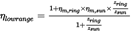
‘Ratio coverage’ means the ratio of the largest to the smallest forward gear ratios in a transmission: φtot = imax/imin ;
(4)
‘Compound transmission’ means a transmission, with a large number of forward gears and/or large ratio coverage, composed of sub-transmissions, which are combined to use most power-transferring parts in several forward gears;
(5)
‘Main section’ means the sub-transmission that has the largest number of forward gears in a compound transmission;
(6)
‘Range section’ means a sub-transmission normally in series connection with the main section in a compound transmission. A range section usually has two shiftable forward gears. The lower forward gears of the complete transmission are embodied using the low range gear. The higher gears are embodied using the high range gear;
(7)
‘Splitter’ means a design that splits the main section gears in two (usually) variants, low- and high split gears, whose gear ratios are close compared to the ratio coverage of the transmission. A splitter can be a separate sub-transmission, an add-on device, integrated with the main section or a combination thereof;
(8)
‘Tooth clutch’ means a clutch where torque is transferred mainly by normal forces between mating teeth. A tooth clutch can either be engaged or disengaged. It is operated in load-free conditions, only (e.g., at gear shifts in a manual transmission);
(9)
‘Angle drive’ means a device that transmits rotational power between non-parallel shafts, often used with transversely oriented engine and longitudinal input to driven axle;
(10)
‘Friction clutch’ means clutch for transfer of propulsive torque, where torque is sustainably transferred by friction forces. A friction clutch can transmit torque while slipping, it can thereby (but does not have to) be operated at start-offs and at powershifts (retained power transfer during a gear shift);
(11)
‘Synchroniser’ means a type of tooth clutch where a friction device is used to equalise the speeds of the rotating parts to be engaged;
(12)
‘Gear mesh efficiency’ means the ratio of output power to input power when transmitted in a forward gear mesh with relative motion;
(13)
‘Crawler gear’ means a low forward gear (with speed reduction ratio that is larger than for the non-crawler gears) that is designed to be used infrequently, e.g., at low-speed manoeuvres or occasional up-hill start-offs;
(14)
‘Power take-off (PTO)’ means a device on a transmission or an engine to which an auxiliary driven device, e.g., a hydraulic pump, can be connected;
(15)
‘Power take-off drive mechanism’ means a device in a transmission that allows the installation of a power take-off (PTO);
(16)
‘Lock-up clutch’ means a friction clutch in a hydrodynamic torque converter; it can connect the input and output sides, thereby eliminating the slip;
(17)
‘Start-off clutch’ means a clutch that adapts speed between engine and driven wheels when the vehicle starts off. The start-off clutch is usually located between engine and transmission;
(18)
‘Synchronised Manual Transmission (SMT)’ means a manually operated transmission with two or more selectable speed ratios that are obtained using synchronisers. Ratio changing is normally achieved during a temporary disconnection of the transmission from the engine using a clutch (usually the vehicle start-off clutch);
(19)
‘Automated Manual Transmission or Automatic Mechanically-engaged Transmission (AMT)’ means an automatically shifting transmission with two or more selectable speed ratios that are obtained using tooth clutches (un-/synchronised). Ratio changing is achieved during a temporary disconnection of the transmission from the engine. The ratio shifts are performed by an electronically controlled system managing the timing of the shift, the operation of the clutch between engine and gearbox and the speed and torque of the engine. The system selects and engages the most suitable forward gear automatically, but can be overridden by the driver using a manual mode;
(20)
‘Dual Clutch Transmission (DCT)’ means an automatically shifting transmission with two friction clutches and several selectable speed ratios that are obtained by the use of tooth clutches. The ratio shifts are performed by an electronically controlled system managing the timing of the shift, the operation of the clutches and the speed and torque of the engine. The system selects the most suitable gear automatically, but can be overridden by the driver using a manual mode;
(21)
‘Retarder’ means an auxiliary braking device in a vehicle powertrain; aimed for permanent braking;
(22)
‘Case S’ means the serial arrangement of a torque converter and the connected mechanical parts of the transmission;
(23)
‘Case P’ means the parallel arrangement of a torque converter and the connected mechanical parts of the transmission (e.g. in power split installations);
(24)
‘Automatic Powershifting Transmission (APT)’ means an automatically shifting transmission with more than two friction clutches and several selectable speed ratios that are obtained mainly by the use of those friction clutches. The ratio shifts are performed by an electronically controlled system managing the timing of the shift, the operation of the clutches and the speed and torque of the engine. The system selects the most suitable gear automatically, but can be overridden by the driver using a manual mode. Shifts are normally performed without traction interruption (friction clutch to friction clutch);
(25)
‘Oil conditioning system’ means an external system that conditions the oil of a transmission at testing. The system circulates oil to and from the transmission. The oil is thereby filtered and/or temperature conditioned;
(26)
‘Smart lubrication system’ means a system that will affect the load independent losses (also called spin losses or drag losses) of the transmission depending on the input torque and/or power flow through the transmission. Examples are controlled hydraulic pressure pumps for brakes and clutches in an APT, controlled variable oil level in the transmission, controlled variable oil flow/pressure for lubrication and cooling in the transmission. Smart lubrication can also include control of the oil temperature of the transmission, but smart lubrication systems that are designed only for controlling the temperature are not considered here, since the transmission testing procedure has fixed testing temperatures;
(27)
‘Transmission electric auxiliary’ means an electric auxiliary used for the function of the transmission during running steady state operation. A typical example is an electric cooling/lubrication pump (but not electric gear shift actuators and electronic control systems including electric solenoid valves, since they are low energy consumers, especially at steady state operation);
(28)
‘Oil type viscosity grade’ means a viscosity grade as defined by SAE J306;
(29)
‘Factory fill oil’ means the oil type viscosity grade that is used for the oil fill in the factory and which is intended to stay in the transmission, torque converter, other torque transferring component or in an additional driveline component for the first service interval;
(30)
‘Gearscheme’ means the arrangement of shafts, gearwheels and clutches in a transmission;
(31)
‘Powerflow’ means the transfer path of power from input to output in a transmission via shafts, gearwheels and clutches.
3.Testing procedure for transmissionsU.K.
For testing the losses of a transmission the torque loss map for each individual transmission type shall be measured. Transmissions may be grouped into families with similar or equal CO2-relevant data following the provisions of Appendix 6 to this Annex.
For the determination of the transmission torque losses, the applicant for a certificate shall apply one of the following methods for each single forward gear (crawler gears excluded).
(1)
Option 1: Measurement of the torque independent losses, calculation of the torque dependent losses.
(2)
Option 2: Measurement of the torque independent losses, measurement of the torque loss at maximum torque and interpolation of the torque dependent losses based on a linear model
(3)
Option 3: Measurement of the total torque loss.
3.1Option 1: Measurement of the torque independent losses, calculation of the torque dependent losses.U.K.
The torque loss Tl ,in on the input shaft of the transmission shall be calculated by
Tl,in (nin , Tin , gear) = T l,in,min_loss + fT * Tin + floss_corr * Tin + T l,in,min_el + fel_corr * Tin
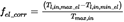
The correction factor for the torque dependent hydraulic torque losses shall be calculated by

The correction factor for the torque dependent electric torque losses shall be calculated by
The torque loss at the input shaft of the transmission caused by the power consumption of transmission electric auxiliary shall be calculated by

where:
Tl,in
=
Torque loss related to input shaft [Nm]
Tl,in,min_loss
=
Torque independent loss at minimum hydraulic loss level (minimum main pressure, cooling/lubrication flows etc.), measured with free rotating output shaft from testing without load [Nm]
Tl,in,max_loss
=
Torque independent loss at maximum hydraulic loss level (maximum main pressure, cooling/lubrication flows etc.), measured with free rotating output shaft from testing without load [Nm]
floss_corr
=
Loss correction for hydraulic loss level depending on input torque [-]
nin
=
Speed at the transmission input shaft (downstream of torque converter, if applicable) [rpm]
fT
=
Torque loss coefficient = 1 – ηT
Tin
=
Torque at the input shaft [Nm]
ηT
=
Torque dependent efficiency (to be calculated); for a direct gear fT = 0,007 (ηT = 0,993) [-]
fel_corr
=
Loss correction for electric power loss level depending on input torque [-]
Tl,in, el
=
Additional torque loss on input shaft by electric consumers [Nm]
Tl,in,min_el
=
Additional torque loss on input shaft by electric consumers corresponding to minimum electric power [Nm]
Tl,in,max_el
=
Additional torque loss on input shaft by electric consumers corresponding to maximum electric power [Nm]
Pel
=
Electric power consumption of electric consumers in transmission measured during transmission loss testing [W]
Tmax,in
=
Maximum allowed input torque for any forward gear in the transmission [Nm]
3.1.1.The torque dependent losses of a transmission system shall be determined as described in the following:U.K.
In case of multiple parallel and nominally equal power flows, e.g., twin countershafts or several planet gearwheels in a planetary gear set, that can be treated as one power flow in this section.
3.1.1.1.For each indirect gear g of common transmissions with a non-split power flow and ordinary, non-planetary gear sets, the following steps shall be performed:U.K.
3.1.1.2.For each active gear mesh, the torque dependent efficiency shall be set to constant values of ηm:U.K.
external – external gear meshes
:
ηm = 0,986
external – internal gear meshes
:
ηm = 0,993
angle drive gear meshes
:
ηm = 0,97
(Angle drive losses may alternatively be determined by separate testing as described in paragraph 6. of this Annex)
3.1.1.3.The product of these torque dependent efficiencies in active gear meshes shall be multiplied with a torque dependent bearing efficiency ηb = 99,5 %.U.K.
3.1.1.4.The total torque dependent efficiency η Tg for the gear g shall be calculated by:U.K.
η Tg = η b * η m,1 * η m,2 * […] * η m,n
3.1.1.5.The torque dependent loss coefficient fTg for the gear g shall be calculated by:U.K.
fTg = 1 – η Tg
3.1.1.6.The torque dependent loss Tl,inTg on the input shaft for gear g shall be calculated by:U.K.
Tl,inTg = fTg * Tin
3.1.1.7.The torque dependent efficiency of the planetary range section in low range state for the special case of transmissions consisting of a countershaft-type main section in series with a planetary range section (with non-rotating ring gearwheel and the planet carrier connected to the output shaft) may, alternatively to the procedure described in 3.1.1.8., be calculated by:U.K.
where:
ηm,ring
=
Torque dependent efficiency of the ring-to-planet gear mesh = 99,3 % [-]
ηm,sun
=
Torque dependent efficiency of the planet-to-sun gear mesh = 98,6 % [-]
zsun
=
Number of teeth of the sun gearwheel of the range section [-]
zring
=
Number of teeth of the ring gearwheel of the range section [-]
The planetary range section shall be regarded as an additional gear mesh within the countershaft main section, and its torque dependent efficiency ηlowrange shall be included in the determination of the total torque dependent efficiencies ηTg for the low-range gears in the calculation in 3.1.1.4.
3.1.1.8.For all other transmission types with more complex split power flows and/or planetary gear sets (e.g. a conventional automatic planetary transmission), the following simplified method shall be used to determine the torque dependent efficiency. The method covers transmission systems composed of ordinary, non-planetary gear sets and/or planetary gear sets of ring-planet-sun type. Alternatively the torque dependent efficiency may be calculated based on VDI Regulation No. 2157. Both calculations shall use the same constant gear mesh efficiency values defined in 3.1.1.2.U.K.
In this case, for each indirect gear g, the following steps shall be performed:
3.1.1.9.Assuming 1 rad/s of input speed and 1 Nm of input torque, a table of speed (Ni ) and torque (Ti ) values for all gearwheels with a fix rotational axis (sun gearwheels, ring gearwheels and ordinary gearwheels) and planet carriers shall be created. Speed and torque values shall follow the right-hand rule, with engine rotation as the positive direction.U.K.
3.1.1.10.For each planetary gear set, the relative speeds sun-to-carrier and ring-to-carrier shall be calculated by:U.K.
Nsun–carrier = Nsun – Ncarrier
Nring–carrier = Nring – Ncarrier
where:
Nsun
=
Rotational speed of sun gearwheel [rad/s]
Nring
=
Rotational speed of ring gearwheel [rad/s]
Ncarrier
=
Rotational speed of carrier [rad/s]
3.1.1.11.The loss-producing powers in the gear meshes shall be computed in the following way:U.K.
For each ordinary, non-planetary gear set, the power P shall be calculated by:
P 1 = N 1 · T 1
P 2 = N 2 · T 2
where:
P=
Power of gear mesh [W]
N=
Rotational speed of gearwheel [rad/s]
T=
Torque of gearwheel [Nm]
For each planetary gear set, the virtual power of sun Pv,sun and ring gearwheels Pv,ring shall be calculated by:
Pv,sun = Tsun · (Nsun – Ncarrier ) = Tsun · Nsun/carrier
Pv,ring = Tring · (Nring – Ncarrier ) = Tring · Nring/carrier
where:
Pv,sun=
Virtual power of sun gearwheel [W]
Pv,ring=
Virtual power of ring gearwheel [W]
Tsun=
Torque of sun gearwheel [Nm]
Tcarrier=
Torque of carrier [Nm]
Tring=
Torque of ring gearwheel [Nm]
Negative virtual power results shall indicate power leaving the gear set, positive virtual power results shall indicate power going into the gear set.
The loss-adjusted powers Padj of the gear meshes shall be computed in the following way:
For each ordinary, non-planetary gear set, the negative power shall be multiplied by the appropriate torque dependent efficiency ηm :
Pi > 0 ⇒ Pi,adj = Pi
Pi < 0 ⇒ Pi,adj = Pi · η mi
where:
Padj=
Loss-adjusted powers of the gear meshes [W]
ηm=
Torque dependent efficiency (appropriate to gear mesh; see 3.1.1.2.) [-]
For each planetary gear set, the negative virtual power shall be multiplied by the torque-dependent efficiencies of sun-to-planet ηmsun and ring-to-planet ηmring :
Pv,i ≥ 0 ⇒ Pi,adj = Pv,i
Pv,i < 0 ⇒ Pi,adj = Pi · ηmsun · ηmring
where:
ηmsun=
Torque dependent efficiency of sun-to-planet [-]
ηmring=
Torque dependent efficiency of ring-to-planet [-]
3.1.1.12.All loss-adjusted power values shall be added up to the torque dependent gear mesh power loss Pm,loss of the transmission system referring to the input power:U.K.
Pm,loss = ΣPi,adj
where:
i
=
All gearwheels with a fix rotational axis [-]
Pm,loss
=
Torque dependent gear mesh power loss of the transmission system [W]
3.1.1.13.The torque dependent loss coefficient for bearings,U.K.
fT,bear = 1 – η bear = 1 – 0,995 = 0,005
and the torque dependent loss coefficient for the gear mesh

shall be added to receive the total torque dependent loss coefficient fT for the transmission system:
fT = fT,gearmesh + fT,bear
where:
fT
=
Total torque dependent loss coefficient for the transmission system [-]
fT,bear
=
Torque dependent loss coefficient for the bearings [-]
fT,gearmesh
=
Torque dependent loss coefficient for the gear meshes [-]
Pin
=
Fixed input power of the transmission; Pin = (1 Nm * 1 rad/s) [W]
3.1.1.14.The torque dependent losses on the input shaft for the specific gear shall be calculated by:U.K.
Tl,inT = fT * Tin
where:
Tl,inT
=
Torque dependent loss related to input shaft [Nm]
Tin
=
Torque at the input shaft [Nm]
3.1.2.The torque independent losses shall be measured in accordance with the procedure described in the following.U.K.
3.1.2.1.General requirementsU.K.
The transmission used for the measurements shall be in accordance with the drawing specifications for series production transmissions and shall be new.
Modifications to the transmission to meet the testing requirements of this Annex, e.g. for the inclusion of measurement sensors or adaption of an external oil conditioning system are permitted.
The tolerance limits in this paragraph refer to measurement values without sensor uncertainty.
[F1Total tested time per transmission individual and gear shall not exceed 5 times the actual testing time per gear (allowing re-testing of transmission if needed due to measuring or rig error).]
Textual Amendments
F1 Substituted by Commission Regulation (EU) 2019/318 of 19 February 2019 amending Regulation (EU) 2017/2400 and Directive 2007/46/EC of the European Parliament and of the Council as regards the determination of the CO2 emissions and fuel consumption of heavy-duty vehicles (Text with EEA relevance).
The same transmission individual may be used for a maximum of 10 different tests, e.g. for tests of transmission torque losses for variants with and without retarder (with different temperature requirements) or with different oils. If the same transmission individual is used for tests of different oils, the recommended factory fill oil shall be tested first.
It is not permitted to run a certain test multiple times to choose a test series with the lowest results.
Upon request of the approval authority the applicant for a certificate shall specify and prove the conformity with the requirements defined in this Annex.
3.1.2.2.Differential measurementsU.K.
To subtract influences caused by the test rig setup (e.g. bearings, clutches) from the measured torque losses, differential measurements are permitted to determine these parasitic torques. The measurements shall be performed at the same speed steps and same test rig bearing temperature(s) ± 3 K used for the testing. The torque sensor measurement uncertainty shall be below 0,3 Nm.
3.1.2.3.Run-inU.K.
On request of the applicant a run-in procedure may be applied to the transmission. The following provisions shall apply for a run-in procedure.
3.1.2.3.1.The procedure shall not exceed 30 hours per gear and 100 hours in total.U.K.
3.1.2.3.2.The application of the input torque shall be limited to 100 % of maximum input torque.U.K.
3.1.2.3.3.The maximum input speed shall be limited by the specified maximum speed for the transmission.U.K.
3.1.2.3.4.The speed and torque profile for the run-in procedure shall be specified by the manufacturer.U.K.
3.1.2.3.5.The run-in procedure shall be documented by the manufacturer with regard to run-time, speed, torque and oil temperature and reported to the Approval authority.U.K.
3.1.2.3.6.The requirements for the ambient temperature (3.1.2.5.1.), measurement accuracy (3.1.4.), test set-up (3.1.8.) and installation angle (3.1.3.2) shall not apply for the run-in procedure.U.K.
3.1.2.4.Pre-conditioningU.K.
3.1.2.4.1.Pre-conditioning of the transmission and the test rig equipment to achieve correct and stable temperatures before the run-in and testing procedures is allowed.U.K.
3.1.2.4.2.The pre-conditioning shall be performed on the direct drive gear without applied torque to the output shaft. If the transmission is not equipped with a direct drive gear, the gear with the ratio closest to 1:1 shall be used.U.K.
3.1.2.4.3.The maximum input speed shall be limited by the specified maximum speed for the transmission.U.K.
3.1.2.4.4.The maximum combined time for the pre-conditioning shall not exceed 50 hours in total for one transmission. Since the complete testing of a transmission may be divided into multiple test sequences (e.g. each gear tested with a separate sequence), the pre-conditioning may be split into several sequences. Each of the single pre-conditioning sequences shall not exceed 60 minutes.U.K.
3.1.2.4.5.The pre-conditioning time shall not be accounted to the time span allocated for the run-in or test procedures.U.K.
3.1.2.5.Test conditionsU.K.
3.1.2.5.1.Ambient temperatureU.K.
The ambient temperature during the test shall be in a range of 25 °C ± 10 K.
The ambient temperature shall be measured 1 m laterally from the transmission.
The ambient temperature limit shall not apply for the run-in procedure.
3.1.2.5.2.Oil temperatureU.K.
Except for the oil, no external heating is allowed.
During measurement (except stabilization) the following temperature limits shall apply:
For SMT/AMT/DCT transmissions, the drain plug oil temperature shall not exceed 83 °C when measuring without retarder and 87 °C with retarder mounted to the transmission. If measurements of a transmission without retarder are to be combined with separate measurements of a retarder, the lower temperature limit shall apply to compensate for the retarder drive mechanism and step-up gear and for the clutch in case of a disengageable retarder.
For torque converter planetary transmissions and for transmissions having more than two friction clutches, the drain plug oil temperature shall not exceed 93 °C without retarder and 97 °C with retarder.
To apply the above defined increased temperature limits for testing with retarder, the retarder shall be integrated in the transmission or have an integrated cooling or oil system with the transmission.
During the run-in, the same oil temperature specifications as for regular testing shall apply.
Exceptional oil temperature peaks up to 110 °C are allowed for the following conditions:
(1)
during run-in procedure up to maximum of 10 % of the applied run-in time,
(2)
during stabilization time.
The oil temperature shall be measured at the drain plug or in the oil sump.
3.1.2.5.3.Oil qualityU.K.
New, recommended first fill oil for the European market shall be used in the test. The same oil fill may be used for run-in and torque measurement.
3.1.2.5.4.Oil viscosityU.K.
If multiple oils are recommended for first fill, they are considered to be equal if the oils have a kinematic viscosity within 10 % of each other at the same temperature (within the specified tolerance band for KV100). Any oil with lower viscosity than the oil used in the test shall be considered to result in lower losses for the tests performed within this option. Any additional first fill oil must fall either in the 10 % tolerance band or have lower viscosity than the oil in the test to be covered by the same certificate.
3.1.2.5.5.Oil level and conditioningU.K.
The oil level shall meet the nominal specifications for the transmission.
If an external oil conditioning system is used, the oil inside the transmission shall be kept to the specified volume that corresponds to the specified oil level.
To guarantee that the external oil conditioning system is not influencing the test, one test point shall be measured with the conditioning system both on and off. The deviation between the two measurements of the torque loss (= input torque) shall be less than 5 %. The test point is specified as follows:
(1)
gear = highest indirect gear,
(2)
input speed = 1 600 rpm,
(3)
temperatures as specified under 3.1.2.5.
For transmissions with hydraulic pressure control or a smart lubrication system, the measurement of torque independent losses shall be performed with two different settings: first with the transmission system pressure set to at least the minimum value for conditions with engaged gear and a second time with the maximum possible hydraulic pressure (see 3.1.6.3.1).
3.1.3.InstallationU.K.
3.1.3.1.The electric machine and the torque sensor shall be mounted to the input side of the transmission. The output shaft shall rotate freely.U.K.
3.1.3.2.The installation of the transmission shall be done with an angle of inclination as for installation in the vehicle according to the homologation drawing ± 1° or at 0° ± 1°.U.K.
3.1.3.3.The internal oil pump shall be included in the transmission.U.K.
3.1.3.4.If an oil cooler is either optional or required with the transmission, the oil cooler may be excluded in the test or any oil cooler may be used in the test.U.K.
3.1.3.5Transmission testing can be done with or without power take-off drive mechanism and/or power take-off. For establishing the power losses of power take-offs and /or power take-off drive mechanism, the values in Annex VII to this regulation are applied. These values assume that the transmission is tested without power take-off drive mechanism and /or power take-off.U.K.
3.1.3.6.Measuring the transmission may be performed with or without single dry clutch (with one or two plates) installed. Clutches of any other type shall be installed during the test.U.K.
3.1.3.7.The individual influence of parasitic loads shall be calculated for each specific test rig setup and torque sensor as described in 3.1.8.U.K.
3.1.4.Measurement equipmentU.K.
The calibration laboratory facilities shall comply with the requirements of either ISO/TS 16949, ISO 9000 series or ISO/IEC 17025. All laboratory reference measurement equipment, used for calibration and/or verification, shall be traceable to national (international) standards.
3.1.4.1.TorqueU.K.
The torque sensor measurement uncertainty shall be below 0,3 Nm.
The use of torque sensors with higher measurement uncertainties is allowed if the part of the uncertainty exceeding 0,3 Nm can be calculated and is added to the measured torque loss as described in 3.1.8. Measurement uncertainty.
3.1.4.2.SpeedU.K.
The uncertainty of the speed sensors shall not exceed ± 1 rpm.
3.1.4.3.TemperatureU.K.
The uncertainty of the temperature sensors for the measurement of the ambient temperature shall not exceed ± 1,5 K.
The uncertainty of the temperature sensors for the measurement of the oil temperature shall not exceed ± 1,5 K.
3.1.4.4.PressureU.K.
The uncertainty of the pressure sensors shall not exceed 1 % of the maximum measured pressure.
3.1.4.5.VoltageU.K.
The uncertainty of the voltmeter shall not exceed 1 % of the maximum measured voltage.
3.1.4.6.Electric currentU.K.
The uncertainty of the amperemeter shall not exceed 1 % of the maximum measured current.
3.1.5.Measurement signals and data recordingU.K.
At least the following signals shall be recorded during the measurement:
(1)
Input torques [Nm]
(2)
Input rotational speeds [rpm]
(3)
Ambient temperature [°C]
(4)
Oil temperature [°C]
If the transmission is equipped with a shift and/or clutch system that is controlled by hydraulic pressure or with a mechanically driven smart lubrication system, additionally to be recorded:
(5)
Oil pressure [kPa]
If the transmission is equipped with transmission electric auxiliary, additionally to be recorded:
(6)
Voltage of transmission electric auxiliary [V]
(7)
Current of transmission electric auxiliary [A]
For differential measurements for the compensation of influences caused by the test rig setup, additionally shall be recorded:
(8)
Test rig bearing temperature [°C]
The sampling and recording rate shall be 100 Hz or higher.
A low pass filter shall be applied to reduce measurement errors.
3.1.6.Test procedureU.K.
3.1.6.1.Zero torque signal compensation:U.K.
The zero-signal of the torque sensor(s) shall be measured. For the measurement the sensor(s) shall be installed in the test rig. The drivetrain of the test rig (input & output) shall be free of load. The measured signal deviation from zero shall be compensated.
3.1.6.2.Speed range:U.K.
The torque loss shall be measured for the following speed steps (speed of the input shaft): 600, 900, 1 200, 1 600, 2 000, 2 500, 3 000, […] rpm up to the maximum speed per gear according to the specifications of the transmission or the last speed step before the defined maximum speed.
The speed ramp (time for the change between two speed steps) shall not extend 20 seconds.
3.1.6.3.Measurement sequence:U.K.
3.1.6.3.1.
If the transmission is equipped with smart lubrication systems and/or transmission electric auxiliaries, the measurement shall be conducted with two measurement settings of of these systems:
A first measurement sequence (3.1.6.3.2. to 3.1.6.3.4.) shall be performed with the lowest power consumption by hydraulical and electrical systems when operated in the vehicle (low loss level).
The second measurement sequence shall be performed with the systems set to work with the highest possible power consumption when operated in the vehicle (high loss level).
3.1.6.3.2.
The measurements shall be performed beginning with the lowest up to the highest speed.
3.1.6.3.3.
For each speed step a minimum of 5 seconds stabilization time within the temperature limits defined in 3.1.2.5 is required. If needed, the stabilization time may be extended by the manufacturer to maximum 60 seconds. Oil and ambient temperatures shall be recorded during the stabilization.
3.1.6.3.4.
After the stabilization time, the measurement signals listed in 3.1.5. shall be recorded for the test point for 05-15 seconds.
3.1.6.3.5.
Each measurement shall be performed two times per measurement setting.
3.1.7.Measurement validationU.K.
3.1.7.1.The arithmetic mean values of torque, speed, (if applicable) voltage and current for the 05-15 seconds measurement shall be calculated for each of the measurements.U.K.
3.1.7.2.The averaged speed deviation shall be below ± 5 rpm of the speed set point for each measured point for the complete torque loss series.U.K.
3.1.7.3.The mechanical torque losses and (if applicable) electrical power consumption shall be calculated for each of the measurements as followed:U.K.
Tloss = Tin
Pel = I * U
It is allowed to subtract influences caused by the test rig setup from the torque losses (3.1.2.2.).
3.1.7.4.The mechanical torque losses and (if applicable) electrical power consumption from the two sets shall be averaged (arithmetic mean values).U.K.
3.1.7.5.The deviation between the averaged torque losses of the two measurement points for each setting shall be below ± 5 % of the average or ± 1 Nm, whichever value is larger. Then, the arithmetic average of the two averaged power values shall be taken.U.K.
3.1.7.6.If the deviation is higher, the largest averaged torque loss value shall be taken or the test shall be repeated for the gear.U.K.
3.1.7.7.The deviation between the averaged electric power consumption (voltage * current) values of the two measurements for each measurement setting shall be below ± 10 % of the average or ± 5 W, whichever value is larger. Then, the arithmetic average of the two averaged power values shall be taken.U.K.
3.1.7.8.If the deviation is higher, the set of averaged voltage and current values giving the largest averaged power consumption shall be taken, or the test shall be repeated for the gear.U.K.
3.1.8.Measurement uncertaintyU.K.
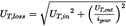
The part of the calculated total uncertainty UT,loss exceeding 0,3 Nm shall be added to Tloss for the reported torque loss Tloss,rep . If UT,loss is smaller than 0,3 Nm, then Tloss,rep = Tloss .
Tloss,rep = Tloss + MAX (0, (UT,loss – 0,3 Nm))
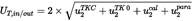
The total uncertainty UT,loss of the torque loss shall be calculated based on the following parameters:
(1)
Temperature effect
(2)
Parasitic loads
(3)
Calibration error (incl. sensitivity tolerance, linearity, hysteresis and repeatability)
The total uncertainty of the torque loss (UT,loss ) is based on the uncertainties of the sensors at 95 % confidence level. The calculation shall be done as the square root of the sum of squares (‘Gaussian law of error propagation’).
wpara = senspara * ipara


where:
Tloss
=
Measured torque loss (uncorrected) [Nm]
Tloss,rep
=
Reported torque loss (after uncertainty correction) [Nm]
UT,loss
=
Total expanded uncertainty of torque loss measurement at 95 % confidence level [Nm]
UT,in
=
Uncertainty of input torque loss measurement [Nm]
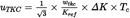
uTKC
=
Uncertainty by temperature influence on current torque signal [Nm]
wtkc
=
Temperature influence on current torque signal per Kref, declared by sensor manufacturer [%]
uTK0
=
Uncertainty by temperature influence on zero torque signal (related to nominal torque) [Nm]
wtk0
=
Temperature influence on zero torque signal per Kref (related to nominal torque), declared by sensor manufacturer [%]
Kref
=
Reference temperature span for uTKC and uTK0, wtk0 and wtkc, declared by sensor manufacturer [K]
ΔK
=
Difference in sensor temperature between calibration and measurement [K]. If the sensor temperature cannot be measured, a default value of ΔK = 15 K shall be used.
Tc
=
Current/measured torque value at torque sensor [Nm]
Tn
=
Nominal torque value of torque sensor [Nm]
ucal
=
Uncertainty by torque sensor calibration [Nm]
Wcal
=
Relative calibration uncertainty (related to nominal torque) [%]
kcal
=
Calibration advancement factor (if declared by sensor manufacturer, otherwise = 1)
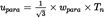
upara
=
Uncertainty by parasitic loads [Nm]
wpara
=
senspara * ipara
Relative influence of forces and bending torques caused by misalignment
senspara
=
Maximum influence of parasitic loads for specific torque sensor declared by sensor manufacturer [%]; if no specific value for parasitic loads is declared by the sensor manufacturer, the value shall be set to 1,0 %
ipara
=
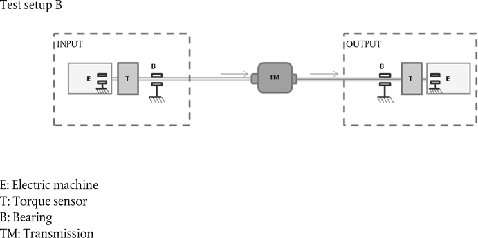
Maximum influence of parasitic loads for specific torque sensor depending on test setup (A/B/C, as defined below).
=
A) 10 % in case of bearings isolating the parasitic forces in front of and behind the sensor and a flexible coupling (or cardan shaft) installed functionally next to the sensor (downstream or upstream); furthermore, these bearings can be integrated in a driving/braking machine (e.g. electric machine) and/or in the transmission as long as the forces in the machine and/or transmission are isolated from the sensor. See figure 1.

=
B) 50 % in case of bearings isolating the parasitic forces in front of and behind the sensor and no flexible coupling installed functionally next to the sensor; furthermore, these bearings can be integrated in a driving/braking machine (e.g. electric machine) and/or in the transmission as long as the forces in the machine and/or transmission are isolated from the sensor. See figure 2.

=
C) 100 % for other setups
3.2.Option 2: Measurement of the torque independent losses, measurement of the torque loss at maximum torque and interpolation of the torque dependent losses based on a linear modelU.K.
Option 2 describes the determination of the torque loss by a combination of measurements and linear interpolation. Measurements shall be performed for the torque independent losses of the transmission and for one load point of the torque dependent losses (maximum input torque). Based on the torque losses at no load and at maximum input torque, the torque losses for the input torques in between shall be calculated with the torque loss coefficient fTlimo .
The torque loss Tl,in on the input shaft of the transmission shall be calculated by
Tl,in (nin , Tin , gear) = Tl,in,min_loss + fTlimo * Tin + T l,in,min_el + fel_corr * Tin
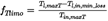
The torque loss coefficient based on the linear model fTlimo shall be calculated by
where:
Tl,in
=
Torque loss related to input shaft [Nm]
Tl,in,min_loss
=
Drag torque loss at transmission input, measured with free rotating output shaft from testing without load [Nm]
nin
=
Speed at the input shaft [rpm]
fTlimo
=
Torque loss coefficient based on linear model [-]
Tin
=
Torque at the input shaft [Nm]
Tin,maxT
=
Maximum tested torque at the input shaft (normally 100 % input torque, refer to 3.2.5.2. and 3.4.4.) [Nm]
Tl,maxT
=
Torque loss related to input shaft with Tin = Tin,maxT
fel_corr
=
Loss correction for electric power loss level depending on input torque [-]
Tl,in,el
=
Additional torque loss on input shaft by electric consumers [Nm]
Tl,in,min_el
=
Additional torque loss on input shaft by electric consumers corresponding to minimum electric power [Nm]
The correction factor for the torque dependent electric torque losses fel_corr and the torque loss at the input shaft of the transmission caused by the power consumption of transmission electric auxiliary Tl,in,el shall be calculated as described in paragraph 3.1.
3.2.1.The torque losses shall be measured in accordance with the procedure described in the following.U.K.
3.2.1.1.General requirements:U.K.
As specified for Option 1 in 3.1.2.1.
3.2.1.2.Differential measurements:U.K.
As specified for Option 1 in 3.1.2.2.
3.2.1.3.Run-inU.K.
As specified for Option 1 in 3.1.2.3.
3.2.1.4.Pre-conditioningU.K.
As specified for Option 3 in 3.3.2.1.
3.2.1.5.Test conditionsU.K.
3.2.1.5.1.Ambient temperatureU.K.
As specified for Option 1 in 3.1.2.5.1.
3.2.1.5.2.Oil temperatureU.K.
As specified for Option 1 in 3.1.2.5.2.
3.2.1.5.3.Oil quality / Oil viscosityU.K.
As specified for Option 1 in 3.1.2.5.3 and 3.1.2.5.4.
3.2.1.5.4.Oil level and conditioningU.K.
As specified for Option 3 in 3.3.3.4.
3.2.2.InstallationU.K.
As specified for Option 1 in 3.1.3. for the measurement of the torque independent losses.
As specified for Option 3 in 3.3.4. for the measurement of the torque dependent losses.
3.2.3.Measurement equipmentU.K.
As specified for Option 1 in 3.1.4. for the measurement of the torque independent losses.
As specified for Option 3 in 3.3.5. for the measurement of the torque dependent losses.
3.2.4.Measurement signals and data recordingU.K.
As specified for Option 1 in 3.1.5 for the measurement of the torque independent losses.
As specified for Option 3 in 3.3.7 for the measurement of the torque dependent losses.
3.2.5.Test procedureU.K.
The torque loss map to be applied to the simulation tool contains the torque loss values of a transmission depending on rotational input speed and input torque.
To determine the torque loss map for a transmission, the basic torque loss map data shall be measured and calculated as specified in this paragraph. The torque loss results shall be complemented in accordance with 3.4 and formatted in accordance with Appendix 12 for the further processing by the simulation tool.
3.2.5.1.The torque independent losses shall be determined by the procedure described in 3.1.1. for the torque independent losses for Option 1 only for the low loss level setting of electric and hydraulic consumers.U.K.
3.2.5.2.Determine the torque dependent losses for each of the gears using the procedure described for Option 3 in 3.3.6., diverging in the applicable torque range:U.K.
Torque range:
The torque losses for each gear shall be measured at 100 % of the maximum transmission input torque per gear.
In the case the output torque exceeds 10 kNm (for a theoretical loss free transmission) or the input power exceeds the specified maximum input power, point 3.4.4. shall apply.
3.2.6.Measurement validationU.K.
As specified for Option 3 in 3.3.8.
3.2.7.Measurement uncertaintyU.K.
As specified for Option 1 in 3.1.8. for the measurement of the torque independent losses.
As specified for Option 3 in 3.3.9. for the measurement of the torque dependent loss.
3.3.Option 3: Measurement of the total torque loss.U.K.
Option 3 describes the determination of the torque loss by full measurement of the torque dependent losses including the torque independent losses of the transmission.
3.3.1.General requirementsU.K.
As specified for Option 1 in 3.1.2.1.
3.3.1.1Differential measurements:U.K.
As specified for Option 1 in 3.1.2.2.
3.3.2.Run-inU.K.
As specified for Option 1 in 3.1.2.3.
3.3.2.1Pre-conditioningU.K.
As specified for Option 1 in 3.1.2.4. with an exception for the following:
The pre-conditioning shall be performed on the direct drive gear without applied torque to the output shaft or target torque on the output shaft set to zero. If the transmission is not equipped with a direct drive gear, the gear with the ratio closest to 1:1 shall be used.
or
The requirements as specified in 3.1.2.4. shall apply, with an exception for the following:
The pre-conditioning shall be performed on the direct drive gear without applied torque to the output shaft or the torque on the output shaft being within +/- 50 Nm. If the transmission is not equipped with a direct drive gear, the gear with the ratio closest to 1:1 shall be used.
or, if the test rig includes a (master friction) clutch at the input shaft:
The requirements as specified in 3.1.2.4. shall apply, with an exception for the following:
The pre-conditioning shall be performed on the direct drive gear without applied torque to the output shaft or without applied torque to the input shaft. If the transmission is not equipped with a direct drive gear, the gear with the ratio closest to 1:1 shall be used.
The transmission would then be driven from the output side. Those proposals could also be combined.
3.3.3.Test conditionsU.K.
3.3.3.1.Ambient temperatureU.K.
As specified for Option 1 in 3.1.2.5.1.
3.3.3.2.Oil temperatureU.K.
As specified for Option 1 in 3.1.2.5.2.
3.3.3.3.Oil quality / Oil viscosityU.K.
As specified for Option 1 in 3.1.2.5.3 and 3.1.2.5.4.
3.3.3.4.Oil level and conditioningU.K.
The requirements as specified in 3.1.2.5.5. shall apply, diverging in the following:
The test point for the external oil conditioning system is specified as follows:
(1)
highest indirect gear,
(2)
input speed = 1 600 rpm,
(3)
input torque = maximum input torque for the highest indirect gear
3.3.4.InstallationU.K.
The test rig shall be driven by electric machines (input and output).
Torque sensors shall be installed at the input and output side of the transmission.
Other requirements as specified in 3.1.3. shall apply.
3.3.5.Measurement equipmentU.K.
For the measurement of the torque independent losses, the measurement equipment requirements as specified for Option 1 in 3.1.4. shall apply.
For the measurement of the torque dependent losses, the following requirements shall apply:
The torque sensor measurement uncertainty shall be below 5 % of the measured torque loss or 1 Nm (whichever value is larger).
The use of torque sensors with higher measurement uncertainties is allowed if the parts of the uncertainty exceeding 5 % or 1 Nm can be calculated and the smaller of those parts is added to the measured torque loss.
The torque measurement uncertainty shall be calculated and included as described under 3.3.9.
Other measurement equipment requirements as specified for Option 1 in 3.1.4. shall apply.
3.3.6.Test procedureU.K.
3.3.6.1.Zero torque signal compensation:U.K.
As specified in 3.1.6.1.
3.3.6.2.Speed rangeU.K.
The torque loss shall be measured for the following speed steps (speed of the input shaft): 600, 900, 1 200, 1 600, 2 000, 2 500, 3 000, […] rpm up to the maximum speed per gear according to the specifications of the transmission or the last speed step before the defined maximum speed.
The speed ramp (time for the change between two speed steps) shall not exceed 20 seconds.
3.3.6.3.Torque rangeU.K.
For each speed step the torque loss shall be measured for the following input torques: 0 (free rotating output shaft), 200, 400, 600, 900, 1 200, 1 600, 2 000, 2 500, 3 000, 3 500, 4 000, […] Nm up to the maximum input torque per gear according to the specifications of the transmission or the last torque step before the defined maximum torque and/or the last torque step before the output torque of 10 kNm.
In the case the output torque exceeds 10 kNm (for a theoretical loss free transmission) or the input power exceeds the specified maximum input power, point 3.4.4. shall apply.
The torque ramp (time for the change between two torque steps) shall not exceed 15 seconds (180 seconds for option 2).
To cover the complete torque range of a transmission in the above defined map, different torque sensors with limited measurement ranges may be used on the input/output side. Therefore the measurement may be divided into sections using the same set of torque sensors. The overall torque loss map shall be composed of these measurement sections.
3.3.6.4.Measurement sequenceU.K.
3.3.6.4.1.The measurements shall be performed beginning with the lowest up to the highest speed.U.K.
3.3.6.4.2.The input torque shall be varied according to the above defined torque steps from the lowest to the highest torque which is covered by the current torque sensors for each speed step.U.K.
3.3.6.4.3.For each speed and torque step a minimum of 5 seconds stabilization time within the temperature limits defined in 3.3.3. is required. If needed, the stabilization time may be extended by the manufacturer to maximum 60 seconds (maximum 180 seconds for option 2). Oil and ambient temperatures shall be recorded during the stabilization.U.K.
3.3.6.4.4.The measurement set shall be performed two times in total. For that purpose, sequenced repetition of sections using the same set of torque sensors is allowed.U.K.
3.3.7.Measurement signals and data recordingU.K.
At least the following signals shall be recorded during the measurement:
(1)
Input and output torques [Nm]
(2)
Input and output rotational speeds [rpm]
(3)
Ambient temperature [°C]
(4)
Oil temperature [°C]
If the transmission is equipped with a shift and/or clutch system that is controlled by hydraulic pressure or with a mechanically driven smart lubrication system, additionally to be recorded:
(5)
Oil pressure [kPa]
If the transmission is equipped with transmission electric auxiliary, additionally to be recorded:
(6)
Voltage of transmission electric auxiliary [V]
(7)
Current of transmission electric auxiliary [A]
For differential measurements for compensation of influences by test rig setup, additionally to be recorded:
(8)
Test rig bearing temperature [°C]
The sampling and recording rate shall be 100 Hz or higher.
A low pass filter shall be applied to avoid measurement errors.
3.3.8.Measurement validationU.K.
3.3.8.1.The arithmetic mean values of torque, speed, if applicable voltage and current for the 05-15 seconds measurement shall be calculated for each of the two measurements.U.K.
3.3.8.2.The measured and averaged speed at the input shaft shall be below ± 5 rpm of the speed set point for each measured operating point for the complete torque loss series. [F1The measured and averaged torque at the input shaft shall be below ± 5 Nm or ± 0,5 % of the torque set point whichever value is larger for each measured operating point for the complete torque loss series.] U.K.
3.3.8.3.The mechanical torque losses and (if applicable) electrical power consumption shall be calculated for each of the measurements as followed:U.K.
Pel = I * U

It is allowed to subtract influences caused by the test rig setup from the torque losses (3.3.2.2.).
3.3.8.4.The mechanical torque losses and (if applicable) electrical power consumption from the two sets shall be averaged (arithmetic mean values).U.K.
3.3.8.5.The deviation between the averaged torque losses of the two measurement sets shall be below ± 5 % of the average or ± 1 Nm (whichever value is larger). The arithmetic average of the two averaged torque loss values shall be taken. If the deviation is higher, the largest averaged torque loss value shall be taken or the test shall be repeated for the gear.U.K.
3.3.8.6.The deviation between the averaged electric power consumption (voltage*current) values of the two measurement sets shall be below ± 10 % of the average or ± 5 W, whichever value is larger. Then, the arithmetic average of the two averaged power values shall be taken.U.K.
3.3.8.7.If the deviation is higher, the set of averaged voltage and current values giving the largest averaged power consumption shall be taken, or the test shall be repeated for the gear.U.K.
3.3.9.Measurement uncertaintyU.K.
The part of the calculated total uncertainty UT,loss exceeding 5 % of Tloss or 1 Nm (ΔUT,loss ), whichever value of ΔUT,loss is smaller, shall be added to Tloss for the reported torque loss Tloss,rep . If UT,loss is smaller than 5 % of Tloss or 1 Nm, then Tloss,rep = Tloss .
Tloss,rep = Tloss + MAX (0, ΔUT,loss )
ΔUT,loss = MIN ((UT,loss – 5 % * Tloss ), (UT,loss – 1 Nm))
For each measurement set, the total uncertainty UT,loss of the torque loss shall be calculated based on the following parameters:
(1)
Temperature effect
(2)
Parasitic loads
(3)
Calibration error (incl. sensitivity tolerance, linearity, hysteresis and repeatability)
The total uncertainty of the torque loss (UT,loss ) is based on the uncertainties of the sensors at 95 % confidence level. The calculation shall be done as the square root of the sum of squares (‘Gaussian law of error propagation’).
wpara = senspara * ipara


where:
Tloss
=
Measured torque loss (uncorrected) [Nm]
Tloss,rep
=
Reported torque loss (after uncertainty correction) [Nm]
UT,loss
=
Total expanded uncertainty of torque loss measurement at 95 % confidence level [Nm]
uT,in/out
=
Uncertainty of input/output torque loss measurement separately for input and output torque sensor[Nm]
igear
=
Gear ratio [-]
uTKC
=
Uncertainty by temperature influence on current torque signal [Nm]
wtkc
=
Temperature influence on current torque signal per Kref, declared by sensor manufacturer [%]
uTK0
=
Uncertainty by temperature influence on zero torque signal (related to nominal torque) [Nm]
wtk0
=
Temperature influence on zero torque signal per Kref (related to nominal torque), declared by sensor manufacturer [%]
Kref
=
Reference temperature span for uTKC and uTK0, wtk0 and wtkc, declared by sensor manufacturer [K]
ΔK
=
Difference in sensor temperature between calibration and measurement [K]. If the sensor temperature cannot be measured, a default value of ΔK = 15 K shall be used.
Tc
=
Current/measured torque value at torque sensor [Nm]
Tn
=
Nominal torque value of torque sensor [Nm]
ucal
=
Uncertainty by torque sensor calibration [Nm]
Wcal
=
Relative calibration uncertainty (related to nominal torque) [%]
kcal
=
calibration advancement factor (if declared by sensor manufacturer, otherwise = 1)
upara
=
Uncertainty by parasitic loads [Nm]
wpara
=
senspara * ipara
Relative influence of forces and bending torques caused by misalignment [%]
senspara
=
Maximum influence of parasitic loads for specific torque sensor declared by sensor manufacturer [%]; if no specific value for parasitic loads is declared by the sensor manufacturer, the value shall be set to 1,0 %
ipara
=
Maximum influence of parasitic loads for specific torque sensor depending on test setup (A/B/C, as defined below).
=
A) 10 % in case of bearings isolating the parasitic forces in front of and behind the sensor and a flexible coupling (or cardan shaft) installed functionally next to the sensor (downstream or upstream); furthermore, these bearings can be integrated in a driving/braking machine (e.g. electric machine) and/or in the transmission as long as the forces in the machine and/or transmission are isolated from the sensor. See figure 3.

=
B) 50 % in case of bearings isolating the parasitic forces in front of and behind the sensor and no flexible coupling installed functionally next to the sensor; furthermore, these bearings can be integrated in a driving/braking machine (e.g. electric machine) and/or in the transmission as long as the forces in the machine and/or transmission are isolated from the sensor. See figure 4.
=
C) 100 % for other setups
3.4.Complement of input files for the simulation toolU.K.
For each gear a torque loss map covering the defined input speed and input torque steps shall be determined with one of the specified testing options or standard torque loss values. For the input file for the simulation tool, this basic torque loss map shall be complemented as described in the following:
3.4.1.In the cases the highest tested input speed was the last speed step below the defined maximum permissible transmission speed, an extrapolation of the torque loss shall be applied up to the maximum speed with linear regression based on the two last measured speed steps.U.K.
3.4.2.In the cases the highest tested input torque was the last torque step below the defined maximum permissible transmission torque, an extrapolation of the torque loss shall be applied up to the maximum torque with linear regression based on the two last measured torque steps for the corresponding speed step. In order to handle engine torque tolerances, etc., the simulation tool will, if required, perform an extrapolation of the torque loss for input torques up to 10 % above said defined maximum permissible transmission torque.U.K.
3.4.3.In the case of extrapolation of the torque loss values for maximum input speed and maximum input torque at the same time, the torque loss for the combined point of highest speed and highest torque shall be calculated with two-dimensional linear extrapolation.U.K.
3.4.4.If the maximum output torque exceeds 10 kNm (for a theoretical loss free transmission), and/or for all speed and torque points with input power higher than the specified maximum input power, the manufacturer may choose to take the torque loss values for all torques higher than 10 kNm, and/or for all speed and torque points with input power higher than the specified maximum input power, respectively, from one of:U.K.
(1)
Calculated fallback values (Appendix 8)
(2)
Option 1
(3)
Option 2 or 3 in combination with a torque sensor for higher output torques (if required)
For cases (i) and (ii) in Option 2, the torque losses at load shall be measured at the input torque that corresponds to output torque 10 kNm and/or the specified maximum input power.
3.4.5.For speeds below the defined minimum speed and the additional input speed step of 0 rpm, the reported torque losses determined for the minimum speed step shall be copied.U.K.
3.4.6.To cover the range of negative input torques during vehicle coasting conditions, the torque loss values for positive input torques shall be copied for the related negative input torques.U.K.
3.4.7.Upon agreement of an approval authority, the torque losses for the input speeds below 1 000 rpm may be replaced by the torque losses at 1 000 rpm when the measurement is technically not possible.U.K.
3.4.8.If the measurement of speed points is technically not possible (e.g. due to natural frequency), the manufacturer may, in agreement with the approval authority, calculate the torque losses by interpolation or extrapolation (limited to max. 1 speed step per gear).U.K.
3.4.9.The torque loss map data shall be formatted and saved as specified in Appendix 12 to this Annex.U.K.
4.Torque converter (TC)U.K.
The torque converter characteristics to be determined for the simulation tool input consist of Tpum 1000 (the reference torque at 1 000 rpm input speed) and μ (the torque ratio of the torque converter). Both are depending on the speed ratio v (= output (turbine) speed / input (pump) speed for the torque converter) of the torque converter.
For determination of the characteristics of the TC, the applicant for a certificate shall apply the following method, irrespective of the chosen option for the assessment of the transmission torque losses.
To take the two possible arrangements of the TC and the mechanical transmission parts into account, the following differentiation between case S and P shall apply:
Case S
:
TC and mechanical transmission parts in serial arrangement
Case P
:
TC and mechanical transmission parts in parallel arrangement (power split installation)
For case S arrangements the TC characteristics may be evaluated either separate from the mechanical transmission or in combination with the mechanical transmission. For case P arrangements the evaluation of TC characteristic is only possible in combination with the mechanical transmission. However, in this case and for the hydromechanical gears subject to measurement the whole arrangement, torque converter and mechanical transmission, is considered as a TC with similar characteristic curves as a sole torque converter.
For the determination of the torque converter characteristics two measurement options may be applied:
(i)
Option A: measurement at constant input speed
(ii)
Option B: measurement at constant input torque according to SAE J643
The manufacturer may choose option A or B for case S and case P arrangements.
For the input to the simulation tool, the torque ratio μ and reference torque Tpum of the torque converter shall be measured for a range of v ≤ 0,95 (= vehicle propulsion mode). The range of v ≥ 1,00 (= vehicle coasting mode) may either be measured or covered by using the standard values of Table 1.
In case of measurements together with a mechanical transmission the overrun point may be different from v = 1,00 and therefor the range of measured speed ratios shall be adjusted accordingly.
In case of use of standard values the data on torque converter characteristics provided to the simulation tool shall only cover the range of v ≤ 0,95 (or the adjusted speed ratio). The simulation tool automatically adds the standard values for overrun conditions.
Table 1
Default values for v ≥ 1,00
| v | μ | Tpum 1000 |
|---|---|---|
| 1,000 | 1,0000 | 0,00 |
| 1,100 | 0,9999 | – 40,34 |
| 1,222 | 0,9998 | – 80,34 |
| 1,375 | 0,9997 | – 136,11 |
| 1,571 | 0,9996 | – 216,52 |
| 1,833 | 0,9995 | – 335,19 |
| 2,200 | 0,9994 | – 528,77 |
| 2,500 | 0,9993 | – 721,00 |
| 3,000 | 0,9992 | – 1 122,0 |
| 3,500 | 0,9991 | – 1 648,0 |
| 4,000 | 0,9990 | – 2 326,0 |
| 4,500 | 0,9989 | – 3 182,0 |
| 5,000 | 0,9988 | – 4 242,0 |
4.1.Option A: Measured torque converter characteristics at constant speedU.K.
4.1.1.General requirementsU.K.
The torque converter used for the measurements shall be in accordance with the drawing specifications for series production torque converters.
Modifications to the TC to meet the testing requirements of this Annex, e.g. for the inclusion of measurement sensors are permitted.
Upon request of the approval authority the applicant for a certificate shall specify and prove the conformity with the requirements defined in this Annex.
4.1.2.Oil temperatureU.K.
The input oil temperature to the TC shall meet the following requirements:
The oil temperature for measurements of the TC separate from the transmission shall be 90 °C + 7/– 3 K.
The oil temperature for measurements of the TC together with the transmission (case S and case P) shall be 90 °C + 20/– 3 K.
The oil temperature shall be measured at the drain plug or in the oil sump.
In case the TC characteristics are measured separately form the transmission, the oil temperature shall be measured prior to entering the converter test drum/bench.
4.1.3.Oil flow rate and pressureU.K.
The input TC oil flow rate and output oil pressure of the TC shall be kept within the specified operational limits for the torque converter, depending on the related transmission type and the tested maximum input speed.
4.1.4.Oil quality/Oil viscosityU.K.
As specified for transmission testing in 3.1.2.5.3 and 3.1.2.5.4.
4.1.5.InstallationU.K.
The torque converter shall be installed on a testbed with a torque sensor, speed sensor and an electric machine installed at the input and output shaft of the TC.
4.1.6.Measurement equipmentU.K.
The calibration laboratory facilities shall comply with the requirements of either ISO/TS 16949, ISO 9000 series or ISO/IEC 17025. All laboratory reference measurement equipment, used for calibration and/or verification, shall be traceable to national (international) standards.
4.1.6.1.TorqueU.K.
The torque sensor measurement uncertainty shall be below 1 % of the measured torque value.
The use of torque sensors with higher measurement uncertainties is allowed if the part of the uncertainty exceeding 1 % of the measured torque can be calculated and is added to the measured torque loss as described in 4.1.7.
4.1.6.2.SpeedU.K.
The uncertainty of the speed sensors shall not exceed ± 1 rpm.
4.1.6.3.TemperatureU.K.
The uncertainty of the temperature sensors for the measurement of the ambient temperature shall not exceed ± 1,5 K.
The uncertainty of the temperature sensors for the measurement of the oil temperature shall not exceed ± 1,5 K.
4.1.7.Test procedureU.K.
4.1.7.1.Zero torque signal compensationU.K.
As specified in 3.1.6.1.
4.1.7.2.Measurement sequenceU.K.
4.1.7.2.1.The input speed npum of the TC shall be fixed to a constant speed within the range of:U.K.
1 000 rpm ≤ npum ≤ 2 000 rpm
4.1.7.2.2.The speed ratio v shall be adjusted by increasing the output speed ntur from 0 rpm up to the set value of npum .U.K.
4.1.7.2.3.The step width shall be 0,1 for the speed ratio range of 0 to 0,6 and 0,05 for the range of 0,6 to 0,95.U.K.
4.1.7.2.4.The upper limit of the speed ratio may be limited to a value below 0,95 by the manufacturer. In this case at least seven evenly distributed points between v = 0 and a value of v < 0,95 have to be covered by the measurement.U.K.
4.1.7.2.5.For each step a minimum of 3 seconds stabilization time within the temperature limits defined in 4.1.2. is required. If needed, the stabilization time may be extended by the manufacturer to maximum 60 seconds. The oil temperature shall be recorded during the stabilization.U.K.
4.1.7.2.6.For each step the signals specified in 4.1.8. shall be recorded for the test point for 3-15 seconds.U.K.
4.1.7.2.7.The measurement sequence (4.1.7.2.1. to 4.1.7.2.6.) shall be performed two times in total.U.K.
4.1.8.Measurement signals and data recordingU.K.
At least the following signals shall be recorded during the measurement:
(1)
Input (pump) torque Tc,pum [Nm]
(2)
Output (turbine) torque Tc,tur [Nm]
(3)
Input rotational (pump) speed npum [rpm]
(4)
Output rotational (turbine) speed ntur [rpm]
(5)
TC input oil temperature KTCin [°C]
The sampling and recording rate shall be 100 Hz or higher.
A low pass filter shall be applied to avoid measurement errors.
4.1.9.Measurement validationU.K.
4.1.9.1.The arithmetic mean values of torque and speed for the 03-15 seconds measurement shall be calculated for each of the two measurements.U.K.
4.1.9.2.The measured torques and speeds from the two sets shall be averaged (arithmetic mean values).U.K.
4.1.9.3.The deviation between the averaged torque of the two measurement sets shall be below ± 5 % of the average or ± 1 Nm (whichever value is larger). The arithmetic average of the two averaged torque values shall be taken. If the deviation is higher, the following value shall be taken for point 4.1.10. and 4.1.11. or the test shall be repeated for the TC.U.K.
for the calculation of ΔUT,pum/tur: smallest averaged torque value for Tc,pum/tur
for the calculation of torque ratio μ: largest averaged torque value for Tc,pum
for the calculation of torque ratio μ: smallest averaged torque value for Tc,tur
for the calculation of reference torque Tpum1000: smallest averaged torque value for Tc,pum
4.1.9.4.The measured and averaged speed and torque at the input shaft shall be below ± 5 rpm and ± 5 Nm of the speed and torque set point for each measured operating point for the complete speed ratio series.U.K.
4.1.10.Measurement uncertaintyU.K.
The part of the calculated measurement uncertainty UT,pum/tur exceeding 1 % of the measured torque Tc,pum/tur shall be used to correct the characteristic value of the TC as defined below.
ΔUT,pum/tur = MAX (0, (UT,pum/tur – 0,01 * Tc,pum/tur))
The uncertainty UT,pum/tur of the torque measurement shall be calculated based on the following parameter:
(i)
Calibration error (incl. sensitivity tolerance, linearity, hysteresis and repeatability)
The uncertainty UT,pum/tur of the torque measurement is based on the uncertainties of the sensors at 95 % confidence level.
UT,pum/tur = 2 * ucal

where:
Tc,pum/tur
=
Current / measured torque value at input/output torque sensor (uncorrected) [Nm]
Tpum
=
Input (pump) torque (after uncertainty correction) [Nm]
UT,pum/tur
=
Uncertainty of input / output torque measurement at 95 % confidence level separately for input and output torque sensor[Nm]
Tn
=
Nominal torque value of torque sensor [Nm]
ucal
=
Uncertainty by torque sensor calibration [Nm]
Wcal
=
Relative calibration uncertainty (related to nominal torque) [%]
kcal
=
Calibration advancement factor (if declared by sensor manufacturer, otherwise = 1)
4.1.11.Calculation of TC characteristicsU.K.
For each measurement point, the following calculations shall be applied to the measurement data:
The torque ratio of the TC shall be calculated by
The speed ratio of the TC shall be calculated by
The reference torque at 1 000 rpm shall be calculated by


where:
μ
=
Torque ratio of the TC [-]
v
=
Speed ratio of the TC [-]
Tc,pum
=
Input (pump) torque (corrected) [Nm]
npum
=
Input rotational (pump) speed [rpm]
ntur
=
Output rotational (turbine) speed [rpm]
Tpum1000
=
Reference torque at 1 000 rpm [Nm]
4.2.Option B: Measurement at constant input torque (in accordance with SAE J643)U.K.
4.2.1.General requirementsU.K.
As specified in 4.1.1.
4.2.2.Oil temperatureU.K.
As specified in 4.1.2.
4.2.3.Oil flow rate and pressureU.K.
As specified in 4.1.3.
4.2.4.Oil qualityU.K.
As specified in 4.1.4.
4.2.5.InstallationU.K.
As specified in 4.1.5.
4.2.6.Measurement equipmentU.K.
As specified in 4.1.6.
4.2.7.Test procedureU.K.
4.2.7.1.Zero torque signal compensationU.K.
As specified in 3.1.6.1.
4.1.7.2.Measurement sequenceU.K.
4.2.7.2.1.The input torque Tpum shall be set to a positive level at npum = 1 000 rpm with the output shaft of the TC held non-rotating (output speed ntur = 0 rpm).U.K.
4.2.7.2.2.The speed ratio v shall be adjusted by increasing the output speed ntur from 0 rpm up to a value of ntur covering the usable range of v with at least seven evenly distributed speed points.U.K.
4.2.7.2.3.The step width shall be 0.1 for the speed ratio range of 0 to 0,6 and 0,05 for the range of 0,6 to 0,95.U.K.
4.2.7.2.4.The upper limit of the speed ratio may be limited to a value below 0,95 by the manufacturer.U.K.
4.2.7.2.5.For each step a minimum of 5 seconds stabilization time within the temperature limits defined in 4.2.2. is required. If needed, the stabilization time may be extended by the manufacturer to maximum 60 seconds. The oil temperature shall be recorded during the stabilization.U.K.
4.2.7.2.6.For each step the values specified in 4.2.8. shall be shall be recorded for the test point for 05-15 seconds.U.K.
4.2.7.2.7.The measurement sequence (4.2.7.2.1. to 4.2.7.2.6.) shall be performed two times in total.U.K.
4.2.8.Measurement signals and data recordingU.K.
As specified in 4.1.8.
4.2.9.Measurement validationU.K.
As specified in 4.1.9.
4.2.10.Measurement uncertaintyU.K.
As specified in 4.1.9.
4.2.11.Calculation of TC characteristicsU.K.
As specified in 4.1.11.
5.Other torque transferring components (OTTC)U.K.
The scope of this section includes engine retarders, transmission retarders, driveline retarders, and components that are treated in the simulation tool as a retarder. These components include vehicle starting devices like a single wet transmission input clutch or hydro-dynamic clutch.
5.1.Methods for establishing retarder drag lossesU.K.
The retarder drag torque loss is a function of the retarder rotor speed. Since the retarder can be integrated in different parts of the vehicle driveline, the retarder rotor speed depends on the drive part (= speed reference) and step-up ratio between drive part and retarder rotor as shown in Table 2.
Table 2
Retarder rotor speeds
where:
istep-up
=
step-up ratio = retarder rotor speed/drive part speed
itransm
=
transmission ratio = transmission input speed/transmission output speed
Retarder configurations that are integrated in the engine and cannot be separated from the engine shall be tested in combination with the engine. This section does not cover these non-separable engine integrated retarders.
Retarders that can be disconnected from the driveline or the engine by any kind of clutch are considered to have zero rotor speed in disconnected condition and therefore have no power losses.
The retarder drag losses shall be measured with one of the following two methods:
(1)
Measurement on the retarder as a stand-alone unit
(2)
Measurement in combination with the transmission
5.1.1.General requirementsU.K.
In case the losses are measured on the retarder as stand-alone unit, the results are affected by the torque losses in the bearings of the test setup. It is permitted to measure these bearing losses and subtract them from the retarder drag loss measurements.
The manufacturer shall guarantee that the retarder used for the measurements is in accordance with the drawing specifications for series production retarders.
Modifications to the retarder to meet the testing requirements of this Annex, e.g. for the inclusion of measurement sensors or the adaption of an external oil conditioning systems are permitted.
Based on the family described in Appendix 6 to this Annex, measured drag losses for transmissions with retarder can be used for the same (equivalent) transmission without retarder.
The use of the same transmission unit for measuring the torque losses of variants with and without retarder is permitted.
Upon request of the approval authority the applicant for a certificate shall specify and prove the conformity with the requirements defined in this Annex.
5.1.2.Run-inU.K.
On request of the applicant a run-in procedure may be applied to the retarder. The following provisions shall apply for a run-in procedure.
5.1.2.1If the manufacturer applies a run-in procedure to the retarder, the run-in time for the retarder shall not exceed 100 hours at zero retarder apply torque. Optionally a share of a maximum of 6 hours with retarder apply torque may be included.U.K.
5.1.3.Test conditionsU.K.
5.1.3.1.Ambient temperatureU.K.
The ambient temperature during the test shall be in a range of 25 °C ± 10 K.
The ambient temperature shall be measured 1 m laterally from the retarder.
5.1.3.2.Ambient pressureU.K.
For magnetic retarders the minimum ambient pressure shall be 899 hPa according to International Standard Atmosphere (ISA) ISO 2533.
5.1.3.3.Oil or water temperatureU.K.
For hydrodynamic retarders:
Except for the fluid, no external heating is allowed.
In case of testing as stand-alone unit, the retarder fluid temperature (oil or water) shall not exceed 87 °C.
In case of testing in combination with transmission, the oil temperature limits for transmission testing shall apply.
5.1.3.4.Oil or water qualityU.K.
New, recommended first fill oil for the European market shall be used in the test.
For water retarders the water quality shall meet the specifications set out by the manufacturer for the retarder. The water pressure shall be set to a fixed value close to vehicle condition (1 ± 0,2 bar relative pressure at retarder input hose).
5.1.3.5.Oil viscosityU.K.
If several oils are recommended for first fill, they are considered to be equal if the oils have a kinematic viscosity within 50 % of each other at the same temperature (within the specified tolerance band for KV100).
5.1.3.6.Oil or water levelU.K.
The oil/water level shall meet the nominal specifications for the retarder.
5.1.4.InstallationU.K.
The electric machine, the torque sensor, and speed sensor shall be mounted at the input side of the retarder or transmission.
The installation of the retarder (and transmission) shall be done with an inclination angle as for installation in the vehicle according to the homologation drawing ± 1° or at 0° ± 1°.
5.1.5.Measurement equipmentU.K.
As specified for transmission testing in 3.1.4.
5.1.6.Test procedureU.K.
5.1.6.1.Zero torque signal compensation:U.K.
As specified for transmission testing in 3.1.6.1.
5.1.6.2.Measurement sequenceU.K.
The torque loss measurement sequence for the retarder testing shall follow the provisions for the transmission testing defined in 3.1.6.3.2. to 3.1.6.3.5.
5.1.6.2.1.Measurement on the retarder as stand-alone unitU.K.
When the retarder is tested as stand-alone unit, torque loss measurements shall be conducted using the following speed points:
200, 400, 600, 900, 1 200, 1 600, 2 000, 2 500, 3 000, 3 500, 4 000, 4 500, 5 000, continued up to the maximum retarder rotor speed.
5.1.6.2.2.Measurement in combination with the transmissionU.K.
5.1.6.2.2.1.In case the retarder is tested in combination with a transmission, the selected transmission gear shall allow the retarder to operate at its maximum rotor speed.U.K.
5.1.6.2.2.The torque loss shall be measured at the operating speeds as indicated for the related transmission testing.U.K.
5.1.6.2.2.3.Measurement points may be added for transmission input speeds below 600 rpm if requested by the manufacturer.U.K.
5.1.6.2.2.4.The manufacturer may separate the retarder losses from the total transmission losses by testing in the order as described below:U.K.
(1)
[F1The load-independent torque loss for the complete transmission including retarder shall be measured as defined in point 3.1. for transmission testing in one of the higher transmission gears:
= T l,in,withret]
(2)
The retarder and related parts shall be replaced with parts required for the equivalent transmission variant without retarder. The measurement of point (1) shall be repeated.
= Tl,in,withoutret
(3)
The load-independent torque loss for the retarder system shall be determined by calculating the differences between the two test data sets
= Tl,in,retsys = Tl,in,withret – Tl,in,withoutret
5.1.7.Measurement signals and data recordingU.K.
As specified for transmission testing in 3.1.5.
5.1.8.Measurement validationU.K.
All recorded data shall be checked and processed as defined for transmission testing in 3.1.7.
5.2.Complement of input files for the simulation toolU.K.
5.2.1Retarder torque losses for speeds below the lowest measurement speed shall be set equal to the measured torque loss at this lowest measurement speed.U.K.
5.2.2In case the retarder losses were separated out from the total losses by calculating the difference in data sets of testing with and without a retarder (see 5.1.6.2.2.4.), the actual retarder rotor speeds depend on the retarder location, and/or selected gear ratio and retarder step-up ratio and thereby may differ from the measured transmission input shaft speeds. The actual retarder rotor speeds relative to the measured drag loss data shall be calculated as described in 5.1. Table 2.U.K.
5.2.3The torque loss map data shall be formatted and saved as specified in Appendix 12 to this Annex.U.K.
6.Additional driveline components (ADC) / angle driveU.K.
6.1.Methods for establishing angle drive lossesU.K.
The angle drive losses shall be determined using one of the following cases:
6.1.1.Case A: Measurement on a separate angle driveU.K.
For the torque loss measurement of a separate angle drive, the three options as defined for the determination of the transmission losses shall apply:
Option 1
:
Measured torque independent losses and calculated torque dependent losses (Transmission test option 1)
Option 2
:
Measured torque independent losses and measured torque dependent losses at full load (Transmission test option 2)
Option 3
:
Measurement under full load points (Transmission test option 3)
The measurement of the angle drive losses shall follow the procedure described for the related transmission test option in paragraph 3 diverging in the following requirements:
6.1.1.1Applicable speed range:U.K.
From 200 rpm (at the shaft to which the angle drive is connected) up to the maximum speed according to specifications of the angle drive or the last speed step before the defined maximum speed.
6.1.1.2Speed step size: 200 rpmU.K.
6.1.2.Case B: Individual measurement of an angle drive connected to a transmissionU.K.
In case the angle drive is tested in combination with a transmission, the testing shall follow one of the defined options for transmission testing:
Option 1
:
Measured torque independent losses and calculated torque dependent losses (Transmission test option 1)
Option 2
:
Measured torque independent losses and measured torque dependent losses at full load (Transmission test option 2)
Option 3
:
Measurement under full load points (Transmission test option 3)
6.1.2.1The manufacturer may separate the angle drive losses from the total transmission losses by testing in the order as described below:U.K.
(1)
The torque loss for the complete transmission including angle drive shall be measured as defined for the applicable transmission testing option
= Tl,in,withad
(2)
The angle drive and related parts shall be replaced with parts required for the equivalent transmission variant without angle drive. The measurement of point (1) shall be repeated.
= Tl,in,withoutad
(3)
The torque loss for the angle drive system shall be determined by calculating the differences between the two test data sets
= Tl,in,adsys = Tl,in,withad – Tl,in,withoutad
6.2.Complement of input files for the simulation toolU.K.
6.2.1.Torque losses for speeds below the above defined minimum speed shall be set equal to the torque loss at the minimum speed.U.K.
6.2.2.In the cases the highest tested angle drive input speed was the last speed step below the defined maximum permissible angle drive speed, an extrapolation of the torque loss shall be applied up to the maximum speed with linear regression based on the two last measured speed steps.U.K.
6.2.3.To calculate the torque loss data for the input shaft of the transmission the angle drive is to be combined with, linear interpolation and extrapolation shall be used.U.K.
7.Conformity of the certified CO2 emissions and fuel consumption related propertiesU.K.
7.1.Every transmission, torque converter (TC), other torque transferring components (OTTC) and additional driveline components (ADC) shall be so manufactured as to conform to the approved type with regard to the description as given in the certificate and its annexes. The conformity of the certified CO2 emissions and fuel consumption related properties procedures shall comply with those set out in Article 12 of Directive 2007/46/EC.U.K.
7.2Torque converter (TC), other torque transferring components (OTTC) and additional driveline components (ADC) shall be excluded from the production conformity testing provisions of section 8 to this annex.U.K.
7.3Conformity of the certified CO2 emissions and fuel consumption related properties shall be checked on the basis of the description in the certificates set out in Appendix 1 to this Annex.U.K.
7.4Conformity of the certified CO2 emissions and fuel consumption related properties shall be assessed in accordance with the specific conditions laid down in this paragraph.U.K.
7.5The manufacturer shall test annually at least the number of transmissions indicated in Table 3 based on the total annual production number of the transmissions produced by the manufacturer. For the purpose of establishing the production numbers, only transmissions which fall under the requirements of this Regulation shall be considered.U.K.
7.6Each transmission which is tested by the manufacturer shall be representative for a specific family. Notwithstanding provisions of the point 7.10., only one transmission per family shall be tested.U.K.
7.7For the total annual production volumes between 1 001 and 10 000 transmissions, the choice of the family for which the tests shall be performed shall be agreed between the manufacturer and the approval authority.U.K.
7.8For the total annual production volumes above 10 000 transmissions, the transmission family with the highest production volume shall always be tested. The manufacturer shall justify (ex. by showing sales numbers) to the approval authority the number of tests which has been performed and the choice of the families. The remaining families for which the tests are to be performed shall be agreed between the manufacturer and the approval authority.U.K.
Table 3
Sample size conformity testing
| Total annual production of transmissions | Number of tests |
|---|---|
| 0 – 1 000 | 0 |
| > 1 000-10 000 | 1 |
| > 10 000-30 000 | 2 |
| > 30 000 | 3 |
| > 100 000 | 4 |
7.9.For the purpose of the conformity of the certified CO2 emissions and fuel consumption related properties testing the approval authority shall identify together with the manufacturer the transmission type(s) to be tested. The approval authority shall ensure that the selected transmission type(s) is manufactured to the same standards as for serial production..U.K.
7.10If the result of a test performed in accordance with point 8 is higher than the one specified in point 8.1.3., 3 additional transmissions from the same family shall be tested. If at least one of them fails, provisions of Article 23 shall apply.U.K.
8.Production conformity testingU.K.
For conformity of the certified CO2 emissions and fuel consumption related properties testing the following method shall apply upon prior agreement between an approval authority and the applicant for a certificate:
8.1Conformity testing of transmissionsU.K.
8.1.1The transmission efficiency shall be determined following the simplified procedure described in this paragraph.U.K.
8.1.2.1All boundary conditions as specified in this Annex for the certification testing shall apply.U.K.
If other boundary conditions for oil type, oil temperature and inclination angle are used, the manufacturer shall clearly show the influence of these conditions and those used for certification regarding efficiency.
8.1.2.2For the measurement the same testing option shall be used as for the certification testing, limited to the operating points specified in this paragraph.U.K.
8.1.2.2.1.In the case Option 1 was used for certification testing, the torque independent losses for the two speeds defined in point 3 of 8.1.2.2.2. shall be measured and used for the calculation of the torque losses at the three highest torque steps.U.K.
In the case Option 2 was used for certification testing, the torque independent losses for the two speeds defined in point 3 of 8.1.2.2.2. shall be measured. The torque dependent losses at maximum torque shall be measured at the same two speeds. The torque losses at the three highest torque steps shall be interpolated as described by the certification procedure.
In the case Option 3 was used for certification testing, the torque losses for the 18 operating points defined in 8.1.2.2.2. shall be measured.
8.1.2.2.2.The efficiency of the transmission shall be determined for 18 operating points defined by the following requirements:U.K.
(1)
Gears to use:
The 3 highest gears of the transmission shall be used for testing.
(2)
Torque range:
The 3 highest torque steps as reported for certification shall be tested.
(3)
Speed range:
The two transmission input speeds of 1 200 rpm and 1 600 rpm shall be tested.
8.1.2.3For each of the 18 operating points, the efficiency of the transmission shall be calculated with:U.K.

where:
η i
=
Efficiency of each operation point 1 to 18
Tout
=
Output torque [Nm]
Tin
=
Input torque [Nm]
nin
=
Input speed [rpm]
nout
=
Output speed [rpm]
8.1.2.4The total efficiency during conformity of the certified CO2 emissions and fuel consumption related properties testing ηA,CoP shall be calculated by the arithmetic mean value of the efficiency of all 18 operating points.U.K.

8.1.3The conformity of the certified CO2 emissions and fuel consumption related properties test is passed when the following condition applies:U.K.
The efficiency of the tested transmission during conformity of the certified CO2 emissions and fuel consumption related properties test ηA,CoP shall not be lower than X % of the type approved transmission efficiency ηA,TA .
ηA,TA – ηA,CoP ≤ X
[F1X shall be replaced by 1,5 % for SMT/AMT/DCT transmissions and 3 % for APT transmissions or transmission with more than 2 friction shift clutches.]
Appendix 1
MODEL OF A CERTIFICATE OF A COMPONENT, SEPARATE TECHNICAL UNIT OR SYSTEM U.K.
Maximum format: A4 (210 × 297 mm)U.K.
CERTIFICATE ON CO2 EMISSIONS AND FUEL CONSUMPTION RELATED PROPERTIES OF A TRANSMISSON / TORQUE CONVERTER / OTHER TORQUE TRANSFERRING COMPONENT/ ADDITIONAL DRIVELINE COMPONENT (1) FAMILY U.K.
| Communication concerning:
| Administration stamp |
of a certificate with regard to Regulation (EC) No 595/2009 as implemented by Regulation (EU) 2017/2400.
Regulation (EC) No XXXXX and Regulation (EU) 2017/2400 as last amended by ….
certification number:
Hash:
Reason for extension:
SECTION IU.K.
0.1Make (trade name of manufacturer):U.K.
0.2Type:U.K.
0.3Means of identification of type, if marked on the componentU.K.
0.3.1Location of the marking:U.K.
0.4Name and address of manufacturer:U.K.
0.5In the case of components and separate technical units, location and method of affixing of the EC approval mark:U.K.
0.6Name(s) and address(es) of assembly plant(s):U.K.
0.7Name and address of the manufacturer's representative (if any)U.K.
SECTION IIU.K.
1.Additional information (where applicable): see AddendumU.K.
1.1.Option used for the determination of the torque lossesU.K.
1.1.1In case of transmission: specify for both output torque ranges 0-10 kNm and > 10 kNm separately for each transmission gearU.K.
2.Approval authority responsible for carrying out the tests:U.K.
3.Date of test reportU.K.
4.Number of test reportU.K.
5.Remarks (if any): see AddendumU.K.
6.PlaceU.K.
7.DateU.K.
8.SignatureU.K.
Attachments:
1.
Information document
2.
Test report
Appendix 2
Transmission information document U.K.
| Information document no.: | Issue: Date of issue: Date of Amendment: |
pursuant to …
[F1Transmission type/family (if applicable):]
…
0.GENERALU.K.
0.1.Name and address of manufacturerU.K.
0.2.Make (trade name of manufacturer):U.K.
0.3.Transmission type:U.K.
0.4.Transmission family:U.K.
0.5.Transmission type as separate technical unit/Transmission family as separate technical unitU.K.
0.6.Commercial name(s) (if available):U.K.
0.7.Means of identification of model, if marked on the transmission:U.K.
0.8.In the case of components and separate technical units, location and method of affixing of the EC approval mark:U.K.
0.9.Name(s) and address(es) of assembly plant(s):U.K.
0.10.Name and address of the manufacturer's representative:U.K.
PART 1U.K. ESSENTIAL CHARACTERISTICS OF THE (PARENT) TRANSMISSION AND THE TRANSMISSION TYPES WITHIN A TRANSMISSION FAMILY
| Parent transmission | Family members | ||||
| or transmission type | |||||
| #1 | #2 | #3 | |||
F20.0GENERALU.K.
F20.1. . . . . . . . . . . . . . . . . . . . . . . . . . . . . . . .U.K.
F20.2. . . . . . . . . . . . . . . . . . . . . . . . . . . . . . . .U.K.
F20.3. . . . . . . . . . . . . . . . . . . . . . . . . . . . . . . .U.K.
F20.4. . . . . . . . . . . . . . . . . . . . . . . . . . . . . . . .U.K.
F20.5. . . . . . . . . . . . . . . . . . . . . . . . . . . . . . . .U.K.
F20.6. . . . . . . . . . . . . . . . . . . . . . . . . . . . . . . .U.K.
F20.7. . . . . . . . . . . . . . . . . . . . . . . . . . . . . . . .U.K.
F20.8. . . . . . . . . . . . . . . . . . . . . . . . . . . . . . . .U.K.
F20.9. . . . . . . . . . . . . . . . . . . . . . . . . . . . . . . .U.K.
Textual Amendments
1.0SPECIFIC TRANSMISSION/TRANSMISSION FAMILY INFORMATIONU.K.
1.1Gear ratio. Gearscheme and powerflowU.K.
1.2Center distance for countershaft transmissionsU.K.
1.3Type of bearings at corresponding positions (if fitted)U.K.
1.4Type of shift elements (tooth clutches, including synchronisers or friction clutches) at corresponding positions (where fitted)U.K.
1.5Single gear width for Option 1 or Single gear width ± 1 mm for Option 2 or Option 3U.K.
1.6Total number of forward gearsU.K.
1.7Number of tooth shift clutchesU.K.
1.8Number of synchronizersU.K.
1.9Number of friction clutch plates (except for single dry clutch with 1 or 2 plates)U.K.
1.10Outer diameter of friction clutch plates (except for single dry clutch with 1 or 2 plates)U.K.
1.11Surface roughness of the teeth (incl. drawings)U.K.
1.12Number of dynamic shaft sealsU.K.
1.13Oil flow for lubrication and cooling per transmission input shaft revolutionU.K.
1.14Oil viscosity at 100 °C (± 10 %)U.K.
1.15System pressure for hydraulically controlled gearboxesU.K.
1.16Specified oil level in reference to central axis and in accordance with the drawing specification (based on average value between lower and upper tolerance) in static or running condition. The oil level is considered as equal if all rotating transmission parts (except for the oil pump and the drive thereof) are located above the specified oil levelU.K.
1.17Specified oil level (± 1 mm)U.K.
1.18Gear ratios [-] and maximum input torque [Nm], maximum input power (kW) and maximum input speed [rpm]U.K.
1 gear
2 gear
3 gear
4 gear
5 gear
6 gear
7 gear
8 gear
9 gear
10 gear
11 gear
12 gear
n gear
LIST OF ATTACHMENTSU.K.
| No.: | Description: | Date of issue: |
|---|---|---|
| 1 | Information on Transmission test conditions | … |
| 2 | … |
Attachment 1 to Transmission information document
Information on test conditions (if applicable)U.K.
Appendix 3
Hydrodynamic torque converter (TC) information document U.K.
| Information document no.: | Issue: Date of issue: Date of Amendment: |
pursuant to …
[F1TC type/family (if applicable):]
…
0.GENERALU.K.
0.1Name and address of manufacturerU.K.
0.2Make (trade name of manufacturer):U.K.
0.3TC type:U.K.
0.4TC family:U.K.
0.5TC type as separate technical unit / TC family as separate technical unitU.K.
0.6Commercial name(s) (if available):U.K.
0.7Means of identification of model, if marked on the TC:U.K.
0.8In the case of components and separate technical units, location and method of affixing of the EC approval mark:U.K.
0.9Name(s) and address(es) of assembly plant(s):U.K.
0.10Name and address of the manufacturer's representative:U.K.
PART 1U.K. ESSENTIAL CHARACTERISTICS OF THE (PARENT) TC AND THE TC TYPES WITHIN A TC FAMILY
| Parent TC or | Family members | ||||
| TC type | #1 | #2 | #3 | ||
F20.0GENERALU.K.
F20.1. . . . . . . . . . . . . . . . . . . . . . . . . . . . . . . .U.K.
F20.2. . . . . . . . . . . . . . . . . . . . . . . . . . . . . . . .U.K.
F20.3. . . . . . . . . . . . . . . . . . . . . . . . . . . . . . . .U.K.
F20.4. . . . . . . . . . . . . . . . . . . . . . . . . . . . . . . .U.K.
F20.5. . . . . . . . . . . . . . . . . . . . . . . . . . . . . . . .U.K.
F20.6. . . . . . . . . . . . . . . . . . . . . . . . . . . . . . . .U.K.
F20.7. . . . . . . . . . . . . . . . . . . . . . . . . . . . . . . .U.K.
F20.8.. . . . . . . . . . . . . . . . . . . . . . . . . . . . . . . .U.K.
F20.9.. . . . . . . . . . . . . . . . . . . . . . . . . . . . . . . .U.K.
1.0SPECIFIC TORQUE CONVERTER/TORQUE CONVERTER FAMILY INFORMATIONU.K.
1.1For hydrodynamic torque converter without mechanical transmission (serial arrangement).U.K.
1.1.1Outer torus diameterU.K.
1.1.2Inner torus diameterU.K.
1.1.3Arrangement of pump (P), turbine (T) and stator (S) in flow directionU.K.
1.1.4Torus widthU.K.
1.1.5Oil type according to test specificationU.K.
1.1.6Blade designU.K.
1.2For hydrodynamic torque converter with mechanical transmission (parallel arrangement).U.K.
1.2.1Outer torus diameterU.K.
1.2.2Inner torus diameterU.K.
1.2.3Arrangement of pump (P), turbine (T) and stator (S) in flow directionU.K.
1.2.4Torus widthU.K.
1.2.5Oil type according to test specificationU.K.
1.2.6Blade designU.K.
1.2.7Gear scheme and power flow in torque converter modeU.K.
1.2.8Type of bearings at corresponding positions (if fitted)U.K.
1.2.9Type of cooling/lubrication pump (referring to parts list)U.K.
1.2.10Type of shift elements (tooth clutches (including synchronisers) OR friction clutches) at corresponding positions where fittedU.K.
1.2.11Oil level according to drawing in reference to central axisU.K.
LIST OF ATTACHMENTSU.K.
| No.: | Description: | Date of issue: |
|---|---|---|
| 1 | Information on Torque Converter test conditions | … |
| 2 | … |
Attachment 1 to Torque Converter information document
Information on test conditions (if applicable)U.K.
1.Method of measurementU.K.
1.1TC with mechanical transmissionU.K.
yes/no
1.2TC as separate unitU.K.
yes/no
Appendix 4
Other torque transferring components (OTTC) information document U.K.
| Information document no.: | Issue: Date of issue: Date of Amendment: |
pursuant to …
[F1OTTC type/family (if applicable):]
…
0.GENERALU.K.
0.1Name and address of manufacturerU.K.
0.2Make (trade name of manufacturer):U.K.
0.3OTTC type:U.K.
0.4OTTC family:U.K.
0.5OTTC type as separate technical unit/OTTC family as separate technical unitU.K.
0.6Commercial name(s) (if available):U.K.
0.7Means of identification of model, if marked on the OTTC:U.K.
0.8In the case of components and separate technical units, location and method of affixing of the EC approval mark:U.K.
0.9Name(s) and address(es) of assembly plant(s):U.K.
0.10Name and address of the manufacturer's representative:U.K.
PART 1U.K. ESSENTIAL CHARACTERISTICS OF THE (PARENT) OTTC AND THE OTTC TYPES WITHIN AN OTTC FAMILY
| Parent OTTC | Family member | ||||
| #1 | #2 | #3 | |||
F20.0GENERALU.K.
F20.1. . . . . . . . . . . . . . . . . . . . . . . . . . . . . . . .U.K.
F20.2. . . . . . . . . . . . . . . . . . . . . . . . . . . . . . . .U.K.
F20.3. . . . . . . . . . . . . . . . . . . . . . . . . . . . . . . .U.K.
F20.4. . . . . . . . . . . . . . . . . . . . . . . . . . . . . . . .U.K.
F20.5. . . . . . . . . . . . . . . . . . . . . . . . . . . . . . . .U.K.
F20.6. . . . . . . . . . . . . . . . . . . . . . . . . . . . . . . .U.K.
F20.7. . . . . . . . . . . . . . . . . . . . . . . . . . . . . . . .U.K.
F20.8.. . . . . . . . . . . . . . . . . . . . . . . . . . . . . . . .U.K.
F20.9.. . . . . . . . . . . . . . . . . . . . . . . . . . . . . . . .U.K.
1.0SPECIFIC OTTC INFORMATIONU.K.
1.1For hydrodynamic torque transferring components (OTTC) / retarderU.K.
1.1.1Outer torus diameterU.K.
1.1.2Torus widthU.K.
1.1.3Blade designU.K.
1.1.4Operating fluidU.K.
1.1.5Outer torus diameter - inner torus diameter (OD-ID)U.K.
1.1.6Number of bladesU.K.
1.1.7Operating fluid viscosityU.K.
1.2For magnetic torque transferring components (OTTC) / RetarderU.K.
1.2.1Drum design (electro magnetic retarder or permanent magnetic retarder)U.K.
1.2.2Outer rotor diameterU.K.
1.2.3Cooling blade designU.K.
1.2.4Blade designU.K.
1.2.5Operating fluidU.K.
1.2.6Outer rotor diameter - inner rotor diameter (OD-ID)U.K.
1.2.7Number of rotorsU.K.
1.2.8Number of cooling blades/bladesU.K.
1.2.9Operating fluid viscosityU.K.
1.2.10Number of armsU.K.
1.3For torque transferring components (OTTC)/hydrodynamic clutchU.K.
1.3.1Outer torus diameterU.K.
1.3.2Torus widthU.K.
1.3.3Blade design.U.K.
1.3.4Operating fluid viscosityU.K.
1.3.5Outer torus diameter - inner torus diameter (OD-ID)U.K.
1.3.6Number of bladesU.K.
LIST OF ATTACHMENTSU.K.
| No.: | Description: | Date of issue: |
|---|---|---|
| 1 | Information on OTTC test conditions | … |
| 2 | … |
Attachment 1 to OTTC information document
Information on test conditions (if applicable)U.K.
1.Method of measurementU.K.
with transmission
yes/no
with engine
yes/no
drive mechanism
yes/no
direct
yes/no
2.Maximum test speed of OTTC main torque absorber e.g. retarder rotor [rpm]U.K.
Appendix 5
Additional driveline components (ADC) information document U.K.
| Information document no.: | Issue: Date of issue: Date of Amendment: |
pursuant to …
[F1ADC type/family (if applicable):]
…
0.GENERALU.K.
0.1Name and address of manufacturerU.K.
0.2Make (trade name of manufacturer):U.K.
0.3ADC type:U.K.
0.4ADC family:U.K.
0.5ADC type as separate technical unit/ADC family as separate technical unitU.K.
0.6Commercial name(s) (if available):U.K.
0.7Means of identification of model, if marked on the ADC:U.K.
0.8In the case of components and separate technical units, location and method of affixing of the EC approval mark:U.K.
0.9Name(s) and address(es) of assembly plant(s):U.K.
0.10Name and address of the manufacturer's representative:U.K.
PART 1U.K. ESSENTIAL CHARACTERISTICS OF THE (PARENT) ADC AND THE ADC TYPES WITHIN AN ADC FAMILY
| Parent-ADC | Family member | ||||
| #1 | #2 | #3 | |||
F20.0GENERALU.K.
F20.1. . . . . . . . . . . . . . . . . . . . . . . . . . . . . . . .U.K.
F20.2. . . . . . . . . . . . . . . . . . . . . . . . . . . . . . . .U.K.
F20.3. . . . . . . . . . . . . . . . . . . . . . . . . . . . . . . .U.K.
F20.4. . . . . . . . . . . . . . . . . . . . . . . . . . . . . . . .U.K.
F20.5. . . . . . . . . . . . . . . . . . . . . . . . . . . . . . . .U.K.
F20.6. . . . . . . . . . . . . . . . . . . . . . . . . . . . . . . .U.K.
F20.7. . . . . . . . . . . . . . . . . . . . . . . . . . . . . . . .U.K.
F20.8.. . . . . . . . . . . . . . . . . . . . . . . . . . . . . . . .U.K.
F20.9.. . . . . . . . . . . . . . . . . . . . . . . . . . . . . . . .U.K.
1.0SPECIFIC ADC/ANGLE DRIVE INFORMATIONU.K.
1.1Gear ratio and gearschemeU.K.
1.2Angle between input/output shaftU.K.
1.3Type of bearings at corresponding positionsU.K.
1.4Number of teeth per gearwheelU.K.
1.5Single gear widthU.K.
1.6Number of dynamic shaft sealsU.K.
1.7Oil viscosity (± 10 %)U.K.
1.8Surface roughness of the teethU.K.
1.9Specified oil level in reference to central axis and in accordance with the drawing specification (based on average value between lower and upper tolerance) in static or running condition. The oil level is considered as equal if all rotating transmission parts (except for the oil pump and the drive thereof) are located above the specified oil levelU.K.
1.10Oil level within (± 1mm).U.K.
LIST OF ATTACHMENTSU.K.
| No.: | Description: | Date of issue: |
|---|---|---|
| 1 | Information on ADC test conditions | … |
| 2 | … |
Attachment 1 to ADC information document
Information on test conditions (if applicable)U.K.
1.Method of measurementU.K.
| with transmission | yes/no |
| drive mechanism | yes/no |
| direct | yes/no |
2.Maximum test speed at ADC input [rpm]U.K.
Appendix 6
Family Concept U.K.
1.GeneralU.K.
A transmission, torque converter, other torque transferring components or additional driveline components family is characterized by design and performance parameters. These shall be common to all members within the family. The manufacturer may decide which transmission, torque converter, other torque transferring components or additional driveline components belong to a family, as long as the membership criteria listed in this Appendix are respected. The related family shall be approved by the Approval Authority. The manufacturer shall provide to the Approval Authority the appropriate information relating to the members of the family.
1.1Special casesU.K.
In some cases there may be interaction between parameters. This shall be taken into consideration to ensure that only transmissions, torque converter, other torque transferring components or additional driveline components with similar characteristics are included within the same family. These cases shall be identified by the manufacturer and notified to the Approval Authority. It shall then be taken into account as a criterion for creating a new transmission, torque converter, other torque transferring components or additional driveline components family.
In case of devices or features, which are not listed in paragraph 9. and which have a strong influence on the level of performance, this equipment shall be identified by the manufacturer on the basis of good engineering practice, and shall be notified to the Approval Authority. It shall then be taken into account as a criterion for creating a new transmission, torque converter, other torque transferring components or additional driveline components family.
1.2The family concept defines criteria and parameters enabling the manufacturer to group transmission, torque converter, other torque transferring components or additional driveline components into families and types with similar or equal CO2-relevant data.U.K.
2.The Approval Authority may conclude that the highest torque loss of the transmission, torque converter, other torque transferring components or additional driveline components family can best be characterized by additional testing. In this case, the manufacturer shall submit the appropriate information to determine the transmission, torque converter, other torque transferring components or additional driveline components within the family likely to have the highest torque loss level.U.K.
If members within a family incorporate other features which may be considered to affect the torque losses, these features shall also be identified and taken into account in the selection of the parent.
3.Parameters defining the transmission familyU.K.
3.1The following criteria shall be the same to all members within a transmission family.U.K.
(a)
Gear ratio, gearscheme and powerflow (for forward gears only, crawler gears excluded);
(b)
Center distance for countershaft transmissions;
(c)
Type of bearings at corresponding positions (if fitted);
(d)
Type of shift elements (tooth clutches, including synchronisers or friction clutches) at corresponding positions (where fitted).
3.2The following criteria shall be common to all members within a transmission family. The application of a specific range to the parameters listed below is permitted after approval of the Approval AuthorityU.K.
(a)
Single gear width ± 1 mm;
(b)
Total number of forward gears;
(c)
Number of tooth shift clutches;
(d)
Number of synchronizers;
(e)
Number of friction clutch plates (except for single dry clutch with 1 or 2 plates);
(f)
Outer diameter of friction clutch plates (except for single dry clutch with 1 or 2 plates);
(g)
Surface roughness of the teeth;
(h)
Number of dynamic shaft seals;
(i)
Oil flow for lubrication and cooling per input shaft revolution;
(j)
Oil viscosity (± 10 %);
(k)
System pressure for hydraulically controlled gearboxes;
(l)
Specified oil level in reference to central axis and in accordance with the drawing specification (based on average value between lower and upper tolerance) in static or running condition. The oil level is considered as equal if all rotating transmission parts (except for the oil pump and the drive thereof) are located above the specified oil level;
(m)
Specified oil level (± 1mm).
4.Choice of the parent transmissionU.K.
The parent transmission shall be selected using the following criteria listed below.
(a)
Highest single gear width for Option 1 or highest Single gear width ± 1 mm for Option 2 or Option 3;
(b)
Highest total number of gears;
(c)
Highest number of tooth shift clutches;
(d)
Highest number of synchronizers;
(e)
Highest number of friction clutch plates (except for single dry clutch with 1 or 2 plates);
(f)
Highest value of the outer diameter of friction clutch plates (except for single dry clutch with 1 or 2 plates);
(g)
Highest value for the surface roughness of the teeth;
(h)
Highest number of dynamic shaft seals;
(i)
Highest oil flow for lubrication and cooling per input shaft revolution;
(j)
Highest oil viscosity;
(k)
Highest system pressure for hydraulically controlled gearboxes;
(l)
Highest specified oil level in reference to central axis and in accordance with the drawing specification (based on average value between lower and upper tolerance) in static or running condition. The oil level is considered as equal if all rotating transmission parts (except for the oil pump and the drive thereof) are located above the specified oil level;
(m)
Highest specified oil level (± 1 mm).
5.Parameters defining the torque converter familyU.K.
5.1The following criteria shall be the same to all members within a torque converter (TC) family.U.K.
5.1.1For hydrodynamic torque converter without mechanical transmission (serial arrangement).U.K.
(a)
Outer torus diameter;
(b)
Inner torus diameter;
(c)
Arrangement of pump (P), turbine (T) and stator (S) in flow direction;
(d)
Torus width;
(e)
Oil type according to test specification;
(f)
Blade design;
5.1.2For hydrodynamic torque converter with mechanical transmission (parallel arrangement).U.K.
(a)
Outer torus diameter;
(b)
Inner torus diameter;
(c)
Arrangement of pump (P), turbine (T) and stator (S) in flow direction;
(d)
Torus width;
(e)
Oil type according to test specification;
(f)
Blade design
(g)
Gear scheme and power flow in torque converter mode
(h)
Type of bearings at corresponding positions (if fitted)
(i)
Type of cooling/lubrication pump (referring to parts list)
(j)
Type of shift elements (tooth clutches (including synchronisers) or friction clutches) at corresponding positions where fitted
5.1.3The following criteria shall be common to all members within a hydrodynamic torque converter with mechanical transmission (parallel arrangement) family. The application of a specific range to the parameters listed below is permitted after approval of the Approval AuthorityU.K.
(a)
Oil level according to drawing in reference to central axis.
6.Choice of the parent torque converterU.K.
6.1For hydrodynamic torque converter without mechanical (serial arrangement) transmission.U.K.
As long as all criteria listed in 5.1.1 are identical every member of the torque converter without mechanical transmission family can be selected as parent.
6.2For hydrodynamic torque converter with mechanical transmission.U.K.
The parent hydrodynamic torque converter with mechanical transmission (parallel arrangement) shall be selected using the following criteria listed below.
(a)
Highest oil level according to drawing in reference to central axis.
7.Parameters defining the other torque transferring components (OTTC) familyU.K.
7.1The following criteria shall be the same to all members within a hydrodynamic torque transferring components / retarder family.U.K.
(a)
Outer torus diameter;
(b)
Torus width;
(c)
Blade design;
(d)
Operating fluid.
7.2The following criteria shall be the same to all members within a magnetic torque transferring components/retarder family.U.K.
(a)
Drum design (electro magnetic retarder or permanent magnetic retarder);
(b)
Outer rotor diameter;
(c)
Cooling blade design;
(d)
Blade design.
7.3The following criteria shall be the same to all members within a torque transferring components / hydrodynamic clutch family.U.K.
(a)
Outer torus diameter;
(b)
Torus width;
(c)
Blade design.
7.4The following criteria shall be common to all members within a hydrodynamic torque transferring components/retarder family. The application of a specific range to the parameters listed below is permitted after approval of the Approval Authority.U.K.
(a)
Outer torus diameter - inner torus diameter (OD-ID);
(b)
Number of blades;
(c)
Operating fluid viscosity (± 50 %).
7.5The following criteria shall be common to all members within a magnetic torque transferring components / retarder family. The application of a specific range to the parameters listed below is permitted after approval of the Approval Authority.U.K.
(a)
Outer rotor diameter - inner rotor diameter (OD-ID);
(b)
Number of rotors;
(c)
Number of cooling blades / blades;
(d)
Number of arms.
7.6The following criteria shall be common to all members within a torque transferring components / hydrodynamic clutch family. The application of a specific range to the parameters listed below is permitted after approval of the Approval Authority.U.K.
(a)
Operating fluid viscosity (± 10 %);
(b)
Outer torus diameter - inner torus diameter (OD-ID);
(c)
Number of blades.
8.Choice of the parent torque transferring componentU.K.
8.1The parent hydrodynamic torque transferring component/retarder shall be selected using the following criteria listed below.U.K.
(a)
Highest value: outer torus diameter – inner torus diameter (OD-ID);
(b)
Highest number of blades;
(c)
Highest operating fluid viscosity.
8.2The parent magnetic torque transferring component / retarder shall be selected using the following criteria listed below.U.K.
(a)
Highest outer rotor diameter – highest inner rotor diameter (OD-ID);
(b)
Highest number of rotors;
(c)
Highest number of cooling blades/blades;
(d)
Highest number of arms.
8.3The parent torque transferring component/hydrodynamic clutch shall be selected using the following criteria listed below.U.K.
(a)
Highest operating fluid viscosity (± 10 %);
(b)
Highest outer torus diameter – highest inner torus diameter (OD-ID);
(c)
Highest number of blades.
9.Parameters defining the additional driveline components familyU.K.
9.1The following criteria shall be the same to all members within an additional driveline components/angle drive family family.U.K.
(a)
Gear ratio and gearscheme;
(b)
Angle between input/output shaft;
(c)
Type of bearings at corresponding positions
9.2The following criteria shall be common to all members within an additional driveline components/angle family. The application of a specific range to the parameters listed below is permitted after approval of the Approval Authority.U.K.
(a)
Single gear width;
(b)
Number of dynamic shaft seals;
(c)
Oil viscosity (± 10 %);
(d)
Surface roughness of the teeth;
(e)
Specified oil level in reference to central axis and in accordance with the drawing specification (based on average value between lower and upper tolerance) in static or running condition. The oil level is considered as equal if all rotating transmission parts (except for the oil pump and the drive thereof) are located above the specified oil level.
10.Choice of the parent additional driveline componentU.K.
10.1The parent additional driveline component / angle drive shall be selected using the following criteria listed below.U.K.
(a)
Highest single gear width;
(a)
Highest number of dynamic shaft seals;
(c)
Highest oil viscosity (± 10 %);
(d)
Highest surface roughness of the teeth;
(e)
Highest specified oil level in reference to central axis and in accordance with the drawing specification (based on average value between lower and upper tolerance) in static or running condition. The oil level is considered as equal if all rotating transmission parts (except for the oil pump and the drive thereof) are located above the specified oil level.
Appendix 7
Markings and numbering U.K.
1.MarkingsU.K.
In the case of a component being certified in accordance with this Annex, the component shall bear:
[F11.1. The manufacturer's name or trade mark U.K.
1.2. The make and identifying type indication as recorded in the information referred to in point 0.2 and 0.3 of Appendices 2 - 5 to this Annex] U.K.
1.3The certification mark (if applicable) as a rectangle surrounding the lower-case letter ‘e’ followed by the distinguishing number of the Member State which has granted the certificate:U.K.
1 for Germany;
2 for France;
3 for Italy;
4 for the Netherlands;
5 for Sweden;
6 for Belgium;
7 for Hungary;
8 for the Czech Republic;
9 for Spain;
11 for the United Kingdom;
12 for Austria;
13 for Luxembourg;
17 for Finland;
18 for Denmark;
19 for Romania;
20 for Poland;
21 for Portugal;
23 for Greece;
24 for Ireland;
25 for Croatia;
26 for Slovenia;
27 for Slovakia;
29 for Estonia;
32 for Latvia;
34 for Bulgaria;
36 for Lithuania;
49 for Cyprus;
50 for Malta
1.4The certification mark shall also include in the vicinity of the rectangle the ‘base approval number’ as specified for Section 4 of the type-approval number set out in Annex VII to Directive 2007/46/EC, preceded by the two figures indicating the sequence number assigned to the latest technical amendment to this Regulation and by an alphabetical character indicating the part for which the certificate has been granted.U.K.
For this Regulation, the sequence number shall be 00.
For this Regulation, the alphabetical character shall be the one laid down in Table 1.
Table 1
| [F1G | Transmission] |
| C | Torque Converter (TC) |
| O | Other torque transferring component (OTTC) |
| D | Additional driveline component (ADC) |
[F11.5. Example of the certification mark U.K.
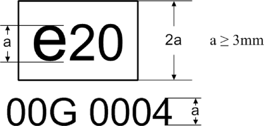
The above certification mark affixed to a transmission, torque converter (TC), other torque transferring component (OTTC) or additional driveline component (ADC) shows that the type concerned has been certified in Poland (e20), pursuant to this Regulation. The first two digits (00) are indicating the sequence number assigned to the latest technical amendment to this Regulation. The following digit indicates that the certification was granted for a transmission (G). The last four digits (0004) are those allocated by the approval authority to the transmission, as the base approval number.]
1.6On request of the applicant for certificate and after prior agreement with the approval authority other type sizes than indicated in 1.5 may be used. Those other type sizes shall remain clearly legible.U.K.
1.7The markings, labels, plates or stickers must be durable for the useful life of the transmission, torque converter (TC), other torque transferring components (OTTC) or additional driveline components (ADC) and must be clearly legible and indelible. The manufacturer shall ensure that the markings, labels, plates or sticker cannot be removed without destroying or defacing them.U.K.
1.8In the case separate certifications are granted by the same approval authority for a transmission, a torque converter, other torque transferring components or additional driveline components and those parts are installed in combination, the indication of one certification mark referred to in point 1.3 is sufficient. This certification mark shall be followed by the applicable markings specified in point 1.4 for the respective transmission, torque converter, other torque transferring component or additional driveline component separated by ‘/’.U.K.
1.9.The certification mark shall be visible when the transmission, torque converter, other torque transferring component or additional driveline component is installed on the vehicle and shall be affixed to a part necessary for normal operation and not normally requiring replacement during component life.U.K.
1.10In the case that torque converter or other torque transferring components are constructed in such a way that they are not accessible and / or visible after being assembled with a transmission the certification mark of the torque converter or other torque transferring component shall be placed on the transmission.U.K.
In the case described in first paragraph, if a torque converter or other torque transferring component have not been certified, ‘–’ instead of the certification number shall be indicated on the transmission next to the alphabetical character specified in point 1.4.
2.NumberingU.K.
[F12.1. Certification number for transmissions, torque converter, other torque transferring component and additional driveline component shall comprise the following: U.K.
eX*YYYY/YYYY*ZZZZ/ZZZZ*X*0000*00
| Section 1 | Section 2 | Section 3 | Additional letter to Section 3 | Section 4 | Section 5 |
|---|---|---|---|---|---|
| Indication of country issuing the certificate | HDV CO 2 certification Regulation (2017/2400) | Latest amending Regulation (ZZZZ/ZZZZ) | See Table 1 of this appendix | Base certification number 0000 | Extension 00] |
Appendix 8
Standard torque loss values - Transmission U.K.
Calculated fallback values based on the maximum rated torque of the transmission:
The torque loss Tl,in related to the input shaft of the transmission shall be calculated by
where:
Tl,in=
Torque loss related to the input shaft [Nm]
Tdx=
Drag torque at x rpm [Nm]
Taddx=
Additional angle drive gear drag torque at x rpm [Nm]
(if applicable)
nin=
Speed at the input shaft [rpm]
fT=
1-η
η=
efficiency
fT=
0,01 for direct gear, 0,04 for indirect gears
fT_add=
0,04 for angle drive gear (if applicable)
Tin=
Torque at the input shaft [Nm]
For transmissions with tooth shift clutches (Synchronised Manual Transmissions (SMT), Automated Manual Transmissions or Automatic Mechanically engaged Transmissions (AMT) and Dual Clutch Transmissions (DCT)) the drag torque Tdx is calculated by
where:
Tmax,in=
Maximum allowed input torque in any forward gear of transmission [Nm]
=
max(Tmax,in,gear)
Tmax,in,gear=
Maximum allowed input torque in gear, where gear = 1, 2, 3,… top gear). For transmissions with hydrodynamic torque converter this input torque shall be the torque at transmission input before torque converter.
For transmissions with friction shift clutches (> 2 friction clutches) the drag torque Tdx is calculated by
Here, ‘friction clutch’ is used in the context of a clutch or brake that operates with friction, and is required for sustained torque transfer in at least one gear.
For transmissions including an angle drive (e.g. bevel gear), the additional angle drive drag torque Taddx shall be included in the calculation of Tdx :
(only if applicable)


Appendix 9
Generic model – torque converter U.K.
Generic torque converter model based on standard technology:
For the determination of the torque converter characteristics a generic torque converter model depending on specific engine characteristics may be applied.
The generic TC model is based on the following characteristic engine data:
nrated
=
Maximum engine speed at maximum power (determined from the engine full-load curve as calculated by the engine pre-processing tool) [rpm]
Tmax
=
Maximum engine torque (determined from the engine full-load curve as calculated by the engine pre-processing tool) [Nm]
Thereby the generic TC characteristics are valid only for a combination of the TC with an engine sharing the same specific characteristic engine data.
Description of the four-point model for the torque capacity of the TC:
Generic torque capacity and generic torque ratio:
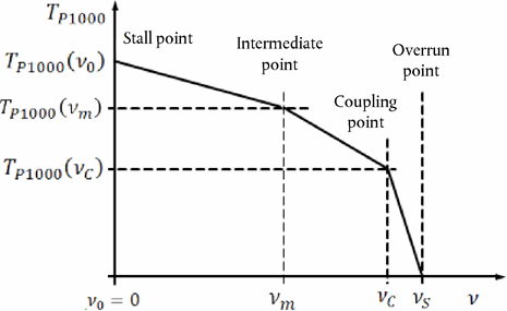
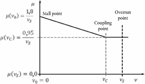
where:


vs
=
Speed ratio at overrun point; 
For TC with rotating housing (Trilock-Type) vs typically is 1. For other TC concepts, especially power split concepts, vs may have values different from 1.

v0
=
Stall point; v 0 = 0 [rpm]

The model requires the following definitions for the calculation of the generic torque capacity:
Stall point:
Stall point at 70 % nominal engine speed.
Engine torque in stall point at 80 % maximum engine torque.
Engine/Pump reference torque in stall point:
Intermediate point:
Intermediate speed ratio vm = 0,6 * vs
Engine/pump reference torque in intermediate point at 80 % of reference torque in stall point:
Coupling point:
Coupling point at 90 % overrun conditions: vc = 0,90 * vs
Engine/pump reference torque in clutch point at 50 % of reference torque in stall point:
Overrun point:
Reference torque at overrun conditions = vs :
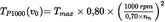


The model requires the following definitions for the calculation of the generic torque ratio:
Stall point:
Torque ratio at stall point v0 = vs = 0:
Intermediate point:
Linear interpolation between stall point and coupling point
Coupling point:
Torque ratio at coupling point vc = 0,9 * vs :
Overrun point:
Torque ratio at overrun conditions = vs :
Efficiency:
n = μ * v


Linear interpolation between the calculated specific points shall be used.
Appendix 10
Standard torque loss values – other torque transferring components U.K.
Calculated standard torque loss values for other torque transferring components:
For hydrodynamic retarders (oil or water), the retarder drag torque shall be calculated by
For magnetic retarders (permanent or electro-magnetic), the retarder drag torque shall be calculated by:


where:
Tretarder
=
Retarder drag loss [Nm]
nretarder
=
Retarder rotor speed [rpm] (see paragraph 5.1 of this Annex)
istep-up
=
Step-up ratio = retarder rotor speed/drive component speed (see paragraph 5.1 of this Annex)
Appendix 11
Standard torque loss values – geared angle drive U.K.
Consistent with the standard torque loss values for the combination of a transmission with a geared angle drive in Appendix 8, the standard torque losses of a geared angle drive without transmission shall be calculated from:

where:
Tl,in
=
Torque loss related to the input shaft of transmission [Nm]
Taddx
=
Additional angle drive gear drag torque at x rpm [Nm]
(if applicable)
nin
=
Speed at the input shaft of transmission [rpm]
fT
=
1-η;
η
=
efficiency
fT_add
=
0,04 for angle drive gear
Tin
=
Torque at the input shaft of transmission [Nm]
Tmax,in
=
Maximum allowed input torque in any forward gear of transmission [Nm]
=
max(Tmax,in,gear)
Tmax,in,gear
=
Maximum allowed input torque in gear, where gear = 1, 2, 3,… top gear)

The standard torque losses obtained by the calculations above may be added to the torque losses of a transmission obtained by Options 1-3 in order to obtain the torque losses for the combination of the specific transmission with an angle drive.
Appendix 12
Input parameters for the simulation tool U.K.
IntroductionU.K.
This Appendix describes the list of parameters to be provided by the transmission, torque converter (TC), other torque transferring components (OTTC) and additional driveline components (ADC) manufacturer as input to the simulation tool. The applicable XML schema as well as example data are available at the dedicated electronic distribution platform.
DefinitionsU.K.
(1) ‘Parameter ID’:
Unique identifier as used in ‘Simulation tool’ for a specific input parameter or set of input data
(2) ‘Type’:
Data type of the parameter
string …
sequence of characters in ISO8859-1 encoding
token …
sequence of characters in ISO8859-1 encoding, no leading/trailing whitespace
date …
date and time in UTC time in the format: YYYY-MM-DDTHH:MM:SSZ with italic letters denoting fixed characters e.g. ‘2002-05-30T09:30:10Z’
integer …
value with an integral data type, no leading zeros, e.g. ‘1800’
double, X …
fractional number with exactly X digits after the decimal sign (‘.’) and no leading zeros e.g. for ‘double, 2’: ‘2345.67’; for ‘double, 4’: ‘45.6780’
(3) ‘Unit’ …
physical unit of the parameter
Set of input parametersU.K.
[F1Table 1
Input parameters ‘ Transmission/General ’
| a DCT shall be declared as transmission type AMT.] | ||||
| Parameter name | Parameter ID | Type | Unit | Description/Reference |
|---|---|---|---|---|
| Manufacturer | P205 | token | [-] | |
| Model | P206 | token | [-] | |
| CertificationNumber | P207 | token | [-] | |
| Date | P208 | dateTime | [-] | Date and time when the component-hash is created |
| AppVersion | P209 | token | [-] | |
| TransmissionType | P076 | string | [-] | Allowed values a : ‘SMT’, ‘AMT’, ‘APT-S’, ‘APT-P’ |
| MainCertificationMethod | P254 | string | [-] | Allowed values: ‘ Option 1 ’ , ‘ Option 2 ’ , ‘ Option 3 ’ , ‘ Standard values ’ |
Table 2
Input parameters ‘Transmission/Gears’ per gear
| Parameter name | Parameter ID | Type | Unit | Description/Reference |
|---|---|---|---|---|
| GearNumber | P199 | integer | [-] | |
| Ratio | P078 | double, 3 | [-] | |
| MaxTorque | P157 | integer | [Nm] | optional |
| MaxSpeed | P194 | integer | [1/min] | optional |
Table 3
Input parameters ‘Transmission/LossMap’ per gear and for each grid point in the loss map
| Parameter name | Parameter ID | Type | Unit | Description/Reference |
|---|---|---|---|---|
| InputSpeed | P096 | double, 2 | [1/min] | |
| InputTorque | P097 | double, 2 | [Nm] | |
| TorqueLoss | P098 | double, 2 | [Nm] |
Table 4
Input parameters ‘TorqueConverter/General’
| Parameter name | Parameter ID | Type | Unit | Description/Reference |
|---|---|---|---|---|
| Manufacturer | P210 | token | [-] | |
| Model | P211 | token | [-] | |
| [F1CertificationNumber | P212 | token | [-] | ] |
| Date | P213 | dateTime | [-] | Date and time when the component-hash is created |
| AppVersion | P214 | string | [-] | |
| CertificationMethod | P257 | string | [-] | Allowed values: ‘Measured’, ‘Standard values’ |
Table 5
Input parameters ‘TorqueConverter/Characteristics’ for each grid point in the characteristic curve
| Parameter name | Parameter ID | Type | Unit | Description/Reference |
|---|---|---|---|---|
| SpeedRatio | P099 | double, 4 | [-] | |
| TorqueRatio | P100 | double, 4 | [-] | |
| InputTorqueRef | P101 | double, 2 | [Nm] |
Table 6
Input parameters ‘Angledrive/General’ (only required if component applicable)
| Parameter name | Parameter ID | Type | Unit | Description/Reference |
|---|---|---|---|---|
| Manufacturer | P220 | token | [-] | |
| Model | P221 | token | [-] | |
| [F1CertificationNumber | P222 | token | [-] | ] |
| Date | P223 | dateTime | [-] | Date and time when the component-hash is created |
| AppVersion | P224 | string | [-] | |
| Ratio | P176 | double, 3 | [-] | |
| CertificationMethod | P258 | string | [-] | Allowed values: ‘Option 1’, ‘Option 2’, ‘Option 3’, ‘Standard values’ |
Table 7
Input parameters ‘Angledrive/LossMap’ for each grid point in the loss map (only required if component applicable)
| Parameter name | Parameter ID | Type | Unit | Description/Reference |
|---|---|---|---|---|
| InputSpeed | P173 | double, 2 | [1/min] | |
| InputTorque | P174 | double, 2 | [Nm] | |
| TorqueLoss | P175 | double, 2 | [Nm] |
Table 8
Input parameters ‘Retarder/General’ (only required if component applicable)
| Parameter name | Parameter ID | Type | Unit | Description/Reference |
|---|---|---|---|---|
| Manufacturer | P225 | token | [-] | |
| Model | P226 | token | [-] | |
| [F1CertificationNumber | P227 | token | [-] | ] |
| Date | P228 | dateTime | [-] | Date and time when the component-hash is created |
| AppVersion | P229 | string | [-] | |
| CertificationMethod | P255 | string | [-] | Allowed values: ‘Measured’, ‘Standard values’ |
Table 9
Input parameters ‘Retarder/LossMap’ for each grid point in the characteristic curve (only required if component applicable)
| Parameter name | Parameter ID | Type | Unit | Description/Reference |
|---|---|---|---|---|
| RetarderSpeed | P057 | double, 2 | [1/min] | |
| TorqueLoss | P058 | double, 2 | [Nm] |
(1)
Delete where not applicable (there are cases where nothing needs to be deleted when more than one entry is applicable)
Options/Help
Print Options
PrintThe Whole Regulation
PrintThis Annex only
You have chosen to open the Whole Regulation
The Whole Regulation you have selected contains over 200 provisions and might take some time to download. You may also experience some issues with your browser, such as an alert box that a script is taking a long time to run.
Would you like to continue?
You have chosen to open Schedules only
Y Rhestrau you have selected contains over 200 provisions and might take some time to download. You may also experience some issues with your browser, such as an alert box that a script is taking a long time to run.
Would you like to continue?
Mae deddfwriaeth ar gael mewn fersiynau gwahanol:
Y Diweddaraf sydd Ar Gael (diwygiedig):Y fersiwn ddiweddaraf sydd ar gael o’r ddeddfwriaeth yn cynnwys newidiadau a wnaed gan ddeddfwriaeth ddilynol ac wedi eu gweithredu gan ein tîm golygyddol. Gellir gweld y newidiadau nad ydym wedi eu gweithredu i’r testun eto yn yr ardal ‘Newidiadau i Ddeddfwriaeth’.
Gwreiddiol (Fel y’i mabwysiadwyd gan yr UE): Mae'r wreiddiol version of the legislation as it stood when it was first adopted in the EU. No changes have been applied to the text.
Gweler y wybodaeth ychwanegol ochr yn ochr â’r cynnwys
Rhychwant ddaearyddol: Indicates the geographical area that this provision applies to. For further information see ‘Frequently Asked Questions’.
Dangos Llinell Amser Newidiadau: See how this legislation has or could change over time. Turning this feature on will show extra navigation options to go to these specific points in time. Return to the latest available version by using the controls above in the What Version box.
Dewisiadau Agor
Dewisiadau gwahanol i agor deddfwriaeth er mwyn gweld rhagor o gynnwys ar y sgrin ar yr un pryd
Rhagor o Adnoddau
Gallwch wneud defnydd o ddogfennau atodol hanfodol a gwybodaeth ar gyfer yr eitem ddeddfwriaeth o’r tab hwn. Yn ddibynnol ar yr eitem ddeddfwriaeth sydd i’w gweld, gallai hyn gynnwys:
- y PDF print gwreiddiol y fel adopted version that was used for the EU Official Journal
- rhestr o newidiadau a wnaed gan a/neu yn effeithio ar yr eitem hon o ddeddfwriaeth
- pob fformat o’r holl ddogfennau cysylltiedig
- slipiau cywiro
- dolenni i ddeddfwriaeth gysylltiedig ac adnoddau gwybodaeth eraill
Llinell Amser Newidiadau
Mae’r llinell amser yma yn dangos y fersiynau gwahanol a gymerwyd o EUR-Lex yn ogystal ag unrhyw fersiynau dilynol a grëwyd ar ôl y diwrnod ymadael o ganlyniad i newidiadau a wnaed gan ddeddfwriaeth y Deyrnas Unedig.
Cymerir dyddiadau fersiynau’r UE o ddyddiadau’r dogfennau ar EUR-Lex ac efallai na fyddant yn cyfateb â’r adeg pan ddaeth y newidiadau i rym ar gyfer y ddogfen.
Ar gyfer unrhyw fersiynau a grëwyd ar ôl y diwrnod ymadael o ganlyniad i newidiadau a wnaed gan ddeddfwriaeth y Deyrnas Unedig, bydd y dyddiad yn cyd-fynd â’r dyddiad cynharaf y daeth y newid (e.e. ychwanegiad, diddymiad neu gyfnewidiad) a weithredwyd i rym. Am ragor o wybodaeth gweler ein canllaw i ddeddfwriaeth ddiwygiedig ar Ddeall Deddfwriaeth.
Rhagor o Adnoddau
Defnyddiwch y ddewislen hon i agor dogfennau hanfodol sy’n cyd-fynd â’r ddeddfwriaeth a gwybodaeth am yr eitem hon o ddeddfwriaeth. Gan ddibynnu ar yr eitem o ddeddfwriaeth sy’n cael ei gweld gall hyn gynnwys:
- y PDF print gwreiddiol y fel adopted fersiwn a ddefnyddiwyd am y copi print
- slipiau cywiro
liciwch ‘Gweld Mwy’ neu ddewis ‘Rhagor o Adnoddau’ am wybodaeth ychwanegol gan gynnwys
- rhestr o newidiadau a wnaed gan a/neu yn effeithio ar yr eitem hon o ddeddfwriaeth
- manylion rhoi grym a newid cyffredinol
- pob fformat o’r holl ddogfennau cysylltiedig
- dolenni i ddeddfwriaeth gysylltiedig ac adnoddau gwybodaeth eraill
 Mae’r holl gynnwys ar gael dan Drwydded Llywodraeth Agored v3.0 ac eithrio ble nodir yn wahanol. Yn ychwanegol mae’r safle hwn â chynnwys sy’n deillio o EUR-Lex, a ailddefnyddiwyd dan delerau Penderfyniad y Comisiwn 2011/833/EU ar ailddefnyddio dogfennau o sefydliadau’r UE. Am ragor o wybodaeth gweler ddatganiad cyhoeddus Swyddfa Gyhoeddiadau’r UE ar ailddefnyddio.