- Y Diweddaraf sydd Ar Gael (Diwygiedig)
- Gwreiddiol (Fel y’i mabwysiadwyd gan yr UE)
Commission Regulation (EU) 2017/2400Dangos y teitl llawn
Commission Regulation (EU) 2017/2400 of 12 December 2017 implementing Regulation (EC) No 595/2009 of the European Parliament and of the Council as regards the determination of the CO2 emissions and fuel consumption of heavy-duty vehicles and amending Directive 2007/46/EC of the European Parliament and of the Council and Commission Regulation (EU) No 582/2011 (Text with EEA relevance)
You are here:

Pa Fersiwn
Nodweddion Uwch
- Dangos Graddfa Ddaearyddol(e.e. Lloegr, Cymru, Yr Alban aca Gogledd Iwerddon)
- Dangos Llinell Amser Newidiadau
Rhagor o Adnoddau
PDF o Fersiynau Diwygiedig
- ddiwygiedig 01/09/20203.68 MB
- ddiwygiedig 01/03/20193.55 MB
Legislation originating from the EU
When the UK left the EU, legislation.gov.uk published EU legislation that had been published by the EU up to IP completion day (31 December 2020 11.00 p.m.). On legislation.gov.uk, these items of legislation are kept up-to-date with any amendments made by the UK since then.


Mae hon yn eitem o ddeddfwriaeth sy’n deillio o’r UE
Mae unrhyw newidiadau sydd wedi cael eu gwneud yn barod gan y tîm yn ymddangos yn y cynnwys a chyfeirir atynt gydag anodiadau.Ar ôl y diwrnod ymadael bydd tair fersiwn o’r ddeddfwriaeth yma i’w gwirio at ddibenion gwahanol. Y fersiwn legislation.gov.uk yw’r fersiwn sy’n weithredol yn y Deyrnas Unedig. Y Fersiwn UE sydd ar EUR-lex ar hyn o bryd yw’r fersiwn sy’n weithredol yn yr UE h.y. efallai y bydd arnoch angen y fersiwn hon os byddwch yn gweithredu busnes yn yr UE. EUR-Lex Y fersiwn yn yr archif ar y we yw’r fersiwn swyddogol o’r ddeddfwriaeth fel yr oedd ar y diwrnod ymadael cyn cael ei chyhoeddi ar legislation.gov.uk ac unrhyw newidiadau ac effeithiau a weithredwyd yn y Deyrnas Unedig wedyn. Mae’r archif ar y we hefyd yn cynnwys cyfraith achos a ffurfiau mewn ieithoedd eraill o EUR-Lex. The EU Exit Web Archive legislation_originated_from_EU_p3
Changes over time for: ANNEX VII
Changes to legislation:
There are outstanding changes not yet made to Commission Regulation (EU) 2017/2400. Any changes that have already been made to the legislation appear in the content and are referenced with annotations.
Changes to Legislation
Revised legislation carried on this site may not be fully up to date. Changes and effects are recorded by our editorial team in lists which can be found in the ‘Changes to Legislation’ area. Where those effects have yet to be applied to the text of the legislation by the editorial team they are also listed alongside the legislation in the affected provisions. Use the ‘more’ link to open the changes and effects relevant to the provision you are viewing.
Changes and effects yet to be applied to Annex VII:
- Annex 7 point 5.1 words substituted by S.I. 2022/1273 reg. 83(6)(a)
Newidiadau ac effeithiau heb eu gweithredu eto ar yr eitem ddeddfwriaeth gyfan a’r darpariaethau cysylltiedig.
- Signature words omitted by S.I. 2022/1273 reg. 82(18)
- Annex 5 Appendix 6 point 1.3 substituted by S.I. 2022/1273 reg. 83(4)(b)(i)
- Annex 5 Appendix 6 point 1.4.1 image substituted by S.I. 2022/1273 reg. 83(4)(b)(iii)(aa)
- Annex 5 Appendix 6 point 1.5.1 image substituted by S.I. 2022/1273 reg. 83(4)(b)(iv)(aa)
- Annex 5 Appendix 4 point 7.4 word substituted by S.I. 2022/1273 reg. 83(4)(a)
- Annex 5 Appendix 6 point 2.1 word substituted by S.I. 2022/1273 reg. 83(4)(b)(v)
- Annex 5 Appendix 6 point 1.4.1 words omitted by S.I. 2022/1273 reg. 83(4)(b)(iii)(bb)
- Annex 5 Appendix 6 point 1.5.1 words omitted by S.I. 2022/1273 reg. 83(4)(b)(iv)(bb)
- Annex 5 Appendix 6 point 1.4 words substituted by S.I. 2022/1273 reg. 83(4)(b)(ii)
- Annex 5 Appendix 6 point 2.1 table words substituted by S.I. 2022/1273 reg. 83(4)(b)(vi)
- Annex 10 Appendix 4 point 1.1 word substituted by S.I. 2022/1273 reg. 83(8)(d)(i)
- Annex 10 Appendix 1 words substituted by S.I. 2022/1273 reg. 83(8)(c)
- Annex 10 Appendix 4 point 1.1 table words substituted by S.I. 2022/1273 reg. 83(8)(d)(ii)
- Annex 7 Appendix 5 point 1.3 substituted by S.I. 2022/1273 reg. 83(6)(c)(i)
- Annex 7 Appendix 5 point 1.4.1 image substituted by S.I. 2022/1273 reg. 83(6)(c)(iii)(aa)
- Annex 7 Appendix 1 s. 1 point 000.5 word substituted by S.I. 2022/1273 reg. 83(6)(b)(ii)
- Annex 7 Appendix 1 words inserted by S.I. 2022/1273 reg. 83(6)(b)(i)(aa)
- Annex 7 Appendix 1 words omitted by S.I. 2022/1273 reg. 83(6)(b)(i)(bb)
- Annex 7 Appendix 5 point 1.4.1 words omitted by S.I. 2022/1273 reg. 83(6)(c)(iii)(bb)
- Annex 7 Appendix 5 point 1.4 words substituted by S.I. 2022/1273 reg. 83(6)(c)(ii)
- Annex 7 Appendix 5 point 2.1 words substituted by S.I. 2022/1273 reg. 83(6)(c)(iv)
- Annex 7 Appendix 5 point 2.1 table words substituted by S.I. 2022/1273 reg. 83(6)(c)(v)
- Annex 8 Appendix 8 point 1.3 substituted by S.I. 2022/1273 reg. 83(7)(d)(i)
- Annex 8 Appendix 8 point 1.4.1 image substituted by S.I. 2022/1273 reg. 83(7)(d)(iii)(aa)
- Annex 8 Appendix 4 table 11 word omitted by S.I. 2022/1273 reg. 83(7)(c)(i)
- Annex 8 Appendix 4 table 13 word omitted by S.I. 2022/1273 reg. 83(7)(c)(i)
- Annex 8 Appendix 4 table 15 word omitted by S.I. 2022/1273 reg. 83(7)(c)(ii)(aa)
- Annex 8 Appendix 4 table 15 word omitted by S.I. 2022/1273 reg. 83(7)(c)(ii)(bb)
- Annex 8 Appendix 1 s. 1 point 000.6 word substituted by S.I. 2022/1273 reg. 83(7)(b)(ii)
- Annex 8 Appendix 8 point 2.1 word substituted by S.I. 2022/1273 reg. 83(7)(d)(iv)
- Annex 8 Appendix 1 words inserted by S.I. 2022/1273 reg. 83(7)(b)(i)(aa)
- Annex 8 Appendix 1 words omitted by S.I. 2022/1273 reg. 83(7)(b)(i)(bb)
- Annex 8 Appendix 8 point 1.4.1 words omitted by S.I. 2022/1273 reg. 83(7)(d)(iii)(bb)
- Annex 8 Appendix 8 point 1.4 words substituted by S.I. 2022/1273 reg. 83(7)(d)(ii)
- Annex 8 Appendix 8 point 2.1 table words substituted by S.I. 2022/1273 reg. 83(7)(d)(v)
- Annex 2 Appendix 2 s. 2 point 2 omitted by S.I. 2022/1273 reg. 83(2)(b)(ii)
- Annex 2 Appendix 2 words inserted by S.I. 2022/1273 reg. 83(2)(b)(i)
- Annex 6 Appendix 7 point 1.3 substituted by S.I. 2022/1273 reg. 83(5)(e)(i)
- Annex 6 Appendix 7 point 1.5 image substituted by S.I. 2022/1273 reg. 83(5)(e)(iii)(aa)
- Annex 6 Appendix 7 point 2.1 word substituted by S.I. 2022/1273 reg. 83(5)(e)(iv)
- Annex 6 Appendix 1 words omitted by S.I. 2022/1273 reg. 83(5)(c)
- Annex 6 Appendix 7 point 1.5 words omitted by S.I. 2022/1273 reg. 83(5)(e)(iii)(bb)
- Annex 6 Appendix 2 point 8 words substituted by S.I. 2022/1273 reg. 83(5)(d)
- Annex 6 Appendix 3 point 8 words substituted by S.I. 2022/1273 reg. 83(5)(d)
- Annex 6 Appendix 4 point 8 words substituted by S.I. 2022/1273 reg. 83(5)(d)
- Annex 6 Appendix 5 point 8 words substituted by S.I. 2022/1273 reg. 83(5)(d)
- Annex 6 Appendix 7 point 1.4 words substituted by S.I. 2022/1273 reg. 83(5)(e)(ii)
- Annex 6 Appendix 7 point 2.1 table words substituted by S.I. 2022/1273 reg. 83(5)(e)(v)
- Art. 3(5) omitted by S.I. 2022/1273 reg. 82(4)(a)
- Art. 3(16) words substituted by S.I. 2022/1273 reg. 82(4)(b)
- Art. 3(20) words substituted by S.I. 2022/1273 reg. 82(4)(c)
- Art. 10(1a) inserted by S.I. 2022/1273 reg. 82(8)(b)
- Annex 10a para. 3(f) words inserted by S.I. 2022/1273 reg. 83(9)(a)
- Annex 10a para. 3(f) table words substituted by S.I. 2022/1273 reg. 83(9)(b)(c)
- Art. 12(8) inserted by S.I. 2022/1273 reg. 82(10)
ANNEX VIIU.K. VERIFYING AXLE DATA
1.IntroductionU.K.
This Annex describes the certification provisions regarding the torque losses of propulsion axles for heavy duty vehicles. Alternatively to the certification of axles the calculation procedure for the standard torque loss as defined in Appendix 3 to this Annex can be applied for the purpose of the determination of vehicle specific CO2 emissions.
2.DefinitionsU.K.
For the purposes of this Annex the following definitions shall apply:
(1)
‘Single reduction axle (SR)’ means a driven axle with only one gear reduction, typically a bevel gear set with or without hypoid offset.
(2)
‘Single portal axle (SP)’ means an axle, that has typically a vertical offset between the rotating axis of the crown gear and the rotating axis of the wheel due to the demand of a higher ground clearance or a lowered floor to allow a low floor concept for inner city buses. Typically, the first reduction is a bevel gear set, the second one a spur gear set with vertical offset close to the wheels.
(3)
‘Hub reduction axle (HR)’ means a driven axle with two gear reductions. The first is typically a bevel gear set with or without hypoid offset. The other is a planetary gear set, what is typically placed in the area of the wheel hubs.
(4)
‘Single reduction tandem axle (SRT)’ means a driven axle that is basically similar to a single driven axle, but has also the purpose to transfer torque from the input flange over an output flange to a further axle. The torque can be transferred with a spur gear set close at the input flange to generate a vertical offset for the output flange. Another possibility is to use a second pinion at the bevel gear set, what takes off torque at the crown wheel.
(5)
‘Hub reduction tandem axle (HRT)’ means a hub reduction axle, what has the possibility to transfer torque to the rear as described under single reduction tandem axle (SRT).
(6)
‘Axle housing’ means the housing parts that are needed for structural capability as well as for carrying the driveline parts, bearings and sealings of the axle.
(7)
‘Pinion’ means a part of a bevel gear set which usually consists of two gears. The pinion is the driving gear which is connected with the input flange. In case of a SRT / HRT, a second pinion can be installed to take off torque from the crown wheel.
(8)
‘Crown wheel’ means a part of a bevel gear set which usually consists of two gears. The crown wheel is the driven gear and is connected with the differential cage.
(9)
‘Hub reduction’ means the planetary gear set that is installed commonly outside the planetary bearing at hub reduction axles. The gear set consists of three different gears. The sun, the planetary gears and the ring gear. The sun is in the centre, the planetary gears are rotating around the sun and are mounted to the planetary carrier that is fixed to the hub. Typically, the number of planetary gears is between three and five. The ring gear is not rotating and fixed to the axle beam.
(10)
‘Planetary gear wheels’ means the gears that rotate around the sun within the ring gear of a planetary gear set. They are assembled with bearings on a planetary carrier, what is joined to a hub.
(11)
‘Oil type viscosity grade’ means a viscosity grade as defined by SAE J306.
(12)
‘Factory fill oil’ means the oil type viscosity grade that is used for the oil fill in the factory and which is intended to stay in the axle for the first service interval.
(13)
‘Axle line’ means a group of axles that share the same basic axle-function as defined in the family concept.
(14)
‘Axle family’ means a manufacturer's grouping of axles which through their design, as defined in Appendix 4 of this Annex, have similar design characteristics and CO2 and fuel consumption properties.
(15)
‘Drag torque’ means the required torque to overcome the inner friction of an axle when the wheel ends are rotating freely with 0 Nm output torque.
(16)
‘Mirror inverted axle casing’ means the axle casing is mirrored regarding to the vertical plane.
(17)
‘Axle input’ means the side of the axle on which the torque is delivered to the axle.
(18)
‘Axle output’ means the side(s) of the axle where the torque is delivered to the wheels.
3.General requirementsU.K.
The axle gears and all bearings, except wheel end bearings used for the measurements, shall not be used.
On request of the applicant different gear ratios can be tested in one axle housing using the same wheel ends.
Different axle ratios of hub reduction axles and single portal axles (HR, HRT, SP) may be measured by exchanging the hub reduction only. The provisions as specified in Appendix 4 to this Annex shall apply.
The total run-time for the optional run-in and the measurement of an individual axle (except for the axle housing and wheel-ends) shall not exceed 120 hours.
For testing the losses of an axle the torque loss map for each ratio of an individual axle shall be measured, however axles can be grouped in axle families following the provisions of Appendix 4 to this Annex.
3.1Run-inU.K.
On request of the applicant a run-in procedure may be applied to the axle. The following provisions shall apply for a run-in procedure.
3.1.1Only factory fill oil shall be used for the run-in procedure. The oil used for the run-in shall not be used for the testing described in paragraph 4.U.K.
3.1.2The speed and torque profile for the run-in procedure shall be specified by the manufacturer.U.K.
3.1.3The run-in procedure shall be documented by the manufacturer with regard to run-time, speed, torque and oil temperature and reported to the approval authority.U.K.
3.1.4The requirements for the oil temperature (4.3.1), measurement accuracy (4.4.7) and test set-up (4.2) do not apply for the run-in procedure.U.K.
4.Testing procedure for axlesU.K.
4.1Test conditionsU.K.
4.1.1Ambient temperatureU.K.
The temperature in the test cell shall be maintained to 25 °C ± 10 °C. The ambient temperature shall be measured within a distance of 1 m to the axle housing. Forced heating of the axle may only be applied by an external oil conditioning system as described in 4.1.5.
4.1.2Oil temperatureU.K.
The oil temperature shall be measured at the centre of the oil sump or at any other suitable point in accordance with good engineering practice. In case of external oil conditioning, alternatively the oil temperature can be measured in the outlet line from the axle housing to the conditioning system within 5 cm downstream the outlet. In both cases the oil temperature shall not exceed 70 °C.
4.1.3Oil qualityU.K.
Only recommended factory fill oils as specified by the axle manufacturer shall be used for the measurement. In the case of testing different gear ratio variants with one axle housing, new oil shall be filled in for each single measurement.
4.1.4Oil viscosityU.K.
If different oils with multiple viscosity grades are specified for the factory fill, the manufacturer shall choose the oil with the highest viscosity grade for performing the measurements on the parent axle.
If more than one oil within the same viscosity grade is specified within one axle family as factory fill oil, the applicant may choose one oil of these for the measurement related to certification.
4.1.5Oil level and conditioningU.K.
The oil level or filling volume shall be set to the maximum level as defined in the manufacturer's maintenance specifications.
An external oil conditioning and filtering system is permitted. The axle housing may be modified for the inclusion of the oil conditioning system.
The oil conditioning system shall not be installed in a way which would enable changing oil levels of the axle in order to raise efficiency or to generate propulsion torques in accordance with good engineering practice.
4.2Test set-upU.K.
For the purpose of the torque loss measurement different test set-ups are permitted as described in paragraph 4.2.3 and 4.2.4.
4.2.1Axle installationU.K.
In case of a tandem axle, each axle shall be measured separately. The first axle with longitudinal differential shall be locked. The output shaft of drive-through axles shall be installed freely rotatable.
4.2.2Installation of torque metersU.K.
4.2.2.1For a test setup with two electric machines, the torque meters shall be installed on the input flange and on one wheel end while the other one is locked.U.K.
4.2.2.2For a test setup with three electric machines, the torque meters shall be installed on the input flange and on each wheel end.U.K.
4.2.2.3Half shafts of different lengths are permitted in a two machine set-up in order to lock the differential and to ensure that both wheel ends are turning.U.K.
4.2.3Test set-up ‘Type A’U.K.
A test set-up considered ‘Type A’ consists of a dynamometer on the axle input side and at least one dynamometer on the axle output side(s). Torque measuring devices shall be installed on the axle input- and output- side(s). For type A set-ups with only one dynamometer on the output side, the free rotating end of the axle shall be locked.
To avoid parasitic losses, the torque measuring devices shall be positioned as close as possible to the axle input- and output- side(s) being supported by appropriate bearings.
Additionally mechanical isolation of the torque sensors from parasitic loads of the shafts, for example by installation of additional bearings and a flexible coupling or lightweight cardan shaft between the sensors and one of these bearings can be applied. Figure 1 shows an example for a test test-up of Type A in a two dynamometer lay-out.
For Type A test set-up configurations the manufacturer shall provide an analysis of the parasitic loads. Based on this analysis the approval authority shall decide about the maximum influence of parasitic loads. However the value ipara cannot be lower than 10 %.
Figure 1 Example of Test set-up ‘Type A’ U.K.

4.2.4Test set-up ‘Type B’U.K.
Any other test set-up configuration is called test set-up Type B. The maximum influence of parasitic loads ipara for those configurations shall be set to 100 %.
Lower values for ipara may be used in agreement with the approval authority.
4.3Test procedureU.K.
To determine the torque loss map for an axle, the basic torque loss map data shall be measured and calculated as specified in paragraph 4.4. [F1The torque loss results shall be complemented in accordance with 4.4.8 and formatted in accordance with Appendix 6 for the further processing by the simulation tool.]
Textual Amendments
F1 Substituted by Commission Regulation (EU) 2019/318 of 19 February 2019 amending Regulation (EU) 2017/2400 and Directive 2007/46/EC of the European Parliament and of the Council as regards the determination of the CO2 emissions and fuel consumption of heavy-duty vehicles (Text with EEA relevance).
4.3.1Measurement equipmentU.K.
The calibration laboratory facilities shall comply with the requirements of either ISO/TS 16949, ISO 9000 series or ISO/IEC 17025. All laboratory reference measurement equipment, used for calibration and/or verification, shall be traceable to national (international) standards.
4.3.1.1Torque measurementU.K.
The torque measurement uncertainty shall be calculated and included as described in paragraph 4.4.7.
The sample rate of the torque sensors shall be in accordance with 4.3.2.1.
4.3.1.2Rotational speedU.K.
The uncertainty of the rotational speed sensors for the measurement of input and output speed shall not exceed ± 2 rpm.
4.3.1.3TemperaturesU.K.
The uncertainty of the temperature sensors for the measurement of the ambient temperature shall not exceed ± 1 °C.
The uncertainty of the temperature sensors for the measurement of the oil temperature shall not exceed ± 0,5 °C.
4.3.2Measurement signals and data recordingU.K.
The following signals shall be recorded for the purpose of the calculation of the torque losses:
(i)
Input and output torques [Nm]
(ii)
Input and/or output rotational speeds [rpm]
(iii)
Ambient temperature [°C]
(iv)
Oil temperature [°C]
(v)
Temperature at the torque sensor
4.3.2.1The following minimum sampling frequencies of the sensors shall be applied:U.K.
Torque: 1 kHz
Rotational speed: 200 Hz
Temperatures: 10 Hz
4.3.2.2The recording rate of the data used to determine the arithmetic mean values of each grid point shall be 10 Hz or higher. The raw data do not need to be reported.U.K.
Signal filtering may be applied in agreement with the approval authority. Any aliasing effect shall be avoided.
4.3.3Torque range:U.K.
The extent of the torque loss map to be measured is limited to:
either an output torque of 10 kNm
or an input torque of 5 kNm
or the maximum engine power tolerated by the manufacturer for a specific axle or in case of multiple driven axles according to the nominal power distribution.
4.3.3.1The manufacturer may extend the measurement up to 20 kNm output torque by means of linear extrapolation of torque losses or by performing measurements up to 20 kNm output torque with steps of 2 000 Nm. For this additional torque range another torque sensor at the output side with a maximum torque of 20 kNm (2-machine layout) or two 10 kNm sensors (3-machine layout) shall be used.U.K.
If the radius of the smallest tire is reduced (e.g. product development) after completing the measurement of an axle or when the physic boundaries of the test stand are reached (e.g. by product development changes), the missing points may be extrapolated by the manufacturer out of the existing map. The extrapolated points shall not exceed more than 10 % of all points in the map and the penalty for these points is 5 % torque loss to be added on the extrapolated points.
4.3.3.2Output torque steps to be measured:U.K.
250 Nm < Tout < 1 000 Nm
:
250 Nm steps
1 000 Nm ≤ Tout ≤ 2 000 Nm
:
500 Nm steps
2 000 Nm ≤ Tout ≤ 10 000 Nm
:
1 000 Nm steps
Tout > 10 000 Nm
:
2 000 Nm steps
If the maximum input torque is limited by the manufacturer, the last torque step to be measured is the one below this maximum without consideration of any losses. In that case an extrapolation of the torque loss shall be applied up to the torque corresponding to the manufacturer's limitation with the linear regression based on the torque steps of the corresponding speed step.
4.3.4Speed rangeU.K.
The range of test speeds shall comprise from 50 rpm wheel speed to the maximum speed. The maximum test speed to be measured is defined by either the maximum axle input speed or the maximum wheel speed, whichever of the following conditions is reached first:
4.3.4.1
The maximum applicable axle input speed may be limited to design specification of the axle.
4.3.4.2
The maximum wheel speed is measured under consideration of the smallest applicable tire diameter at a vehicle speed of 90 km/h for trucks and 110 km/h for coaches. If the smallest applicable tire diameter is not defined, paragraph 4.3.4.1 shall apply.
4.3.5Wheel speed steps to be measuredU.K.
The wheel speed step width for testing shall be 50 rpm.
4.4Measurement of torque loss maps for axlesU.K.
4.4.1Testing sequence of the torque loss mapU.K.
For each speed step the torque loss shall be measured for each output torque step starting from 250 Nm upward to the maximum and downward to the minimum. The speed steps can be run in any order. [F2The torque measurement sequence shall be performed and recorded twice.]
Textual Amendments
Interruptions of the sequence for cooling or heating purposes are permitted.
4.4.2Measurement durationU.K.
[F1The measurement duration for each single grid point shall be 5-20 seconds.]
4.4.3Averaging of grid pointsU.K.
[F1The recorded values for each grid point within the 5-20 seconds interval in accordance with point 4.4.2 shall be averaged to an arithmetic mean.]
All four averaged intervals of corresponding speed and torque grid points from both sequences measured each upward and downward shall be averaged to an arithmetic mean and result into one torque loss value.
4.4.4The torque loss (at input side) of the axle shall be calculated byU.K.

where:
Tloss
=
Torque loss of the axle at the input side [Nm]
Tin
=
Input torque [Nm]
igear
=
Axle gear ratio [-]
Tout
=
Output torque [Nm]
4.4.5Measurement validationU.K.
[F14.4.5.1 The averaged speed values per grid point (5-20 s interval) shall not deviate from the setting values by more than ± 5 rpm for the output speed.] U.K.
4.4.5.2The averaged output torque values as described under 4.4.3 for each grid point shall not deviate more than ± 20 Nm or ± 1 % from the torque set point for the according grid point, whichever is the higher value.U.K.
4.4.5.3If the above specified criteria are not met the measurement is void. In this case, the measurement for the entire affected speed step shall be repeated. After passing the repeated measurement, the data shall be consolidated.U.K.
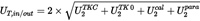
4.4.6Uncertainty calculationU.K.
The total uncertainty UT,loss of the torque loss shall be calculated based on the following parameters:
i.
Temperature effect
ii.
Parasitic loads
iii.
Uncertainty (incl. sensitivity tolerance, linearity, hysteresis and repeatability)
The total uncertainty of the torque loss (UT,loss) is based on the uncertainties of the sensors at 95 % confidence level. The calculation shall be done for each applied sensor (e.g. three machine lay out: UT,in, UT,out,1, UTout,2) as the square root of the sum of squares (‘Gaussian law of error propagation’).


wpara = senspara * ipara
where:
UT,in/out
=
Uncertainty of input/output torque loss measurement separately for input and output torque; [Nm]
igear
=
Axle gear ratio [-]
UTKC
=
Uncertainty by temperature influence on current torque signal; [Nm]
wtkc
=
Temperature influence on current torque signal per Kref, declared by sensor manufacturer; [%]
UTK0
=
Uncertainty by temperature influence on zero torque signal (related to nominal torque) [Nm]
wtk0
=
Temperature influence on zero torque signal per Kref (related to nominal torque), declared by sensor manufacturer; [%]
Kref
=
Reference temperature span for tkc and tk0, declared by sensor manufacturer; [°C]
ΔK
=
Absolute difference in sensor temperature measured at torque sensor between calibration and measurement; If the sensor temperature cannot be measured, a default value of ΔK = 15 K shall be used [°C]
Tc
=
Current/measured torque value at torque sensor; [Nm]
Tn
=
Nominal torque value of torque sensor; [Nm]
Ucal
=
Uncertainty by torque sensor calibration; [Nm]
wcal
=
Relative calibration uncertainty (related to nominal torque); [%]
kcal
=
calibration advancement factor (if declared by sensor manufacturer, otherwise = 1)
Upara
=
Uncertainty by parasitic loads; [Nm]
wpara
=
senspara * ipara
Relative influence of forces and bending torques caused by misalignment
senspara
=
Maximum influence of parasitic loads for specific torque sensor declared by sensor manufacturer [%]; if no specific value for parasitic loads is declared by the sensor manufacturer, the value shall be set to 1,0 %
ipara
=
Maximum influence of parasitic loads for specific torque sensor depending on test set-up as indicated in section 4.2.3 and 4.2.4 of this annex.
4.4.7Assessment of total uncertainty of the torque lossU.K.
In the case the calculated uncertainties UT,in/out are below the following limits, the reported torque loss Tloss,rep shall be regarded as equal to the measured torque loss Tloss .
UT,in : 7,5 Nm or 0,25 % of the measured torque, whichever allowed uncertainty value is higher
UT,out : 15 Nm or 0,25 % of the measured torque, whichever allowed uncertainty value is higher
In the case of higher calculated uncertainties, the part of the calculated uncertainty exceeding the above specified limits shall be added to Tloss for the reported torque loss Tloss,rep as follows:
If the limits of UT,in are exceeded:
Tloss,rep = Tloss + ΔUTin
ΔUT,in = MIN((UT,in – 0,25 % * Tc) or (UT,in – 7,5 Nm))
If limits of UT,out out are exceeded:
Tloss,rep = Tloss + ΔUT,out/igear
ΔUT,out = MIN((UT,out – 0,25 % * Tc) or (UT,out – 15Nm))
where:
UT,in/out
=
Uncertainty of input/output torque loss measurement separately for input and output torque; [Nm]
igear
=
Axle gear ratio [-]
ΔUT
=
The part of the calculated uncertainty exceeding the specified limits
4.4.8Complement of torque loss map dataU.K.
4.4.8.1If the torque values exceed the upper range limit linear extrapolation shall be applied. For the extrapolation the slope of linear regression based on all measured torque points for the corresponding speed step shall be applied.U.K.
4.4.8.2For the output torque range values below 250 Nm the torque loss values of the 250 Nm point shall be applied.U.K.
4.4.8.3For 0 rpm wheel speed rpm the torque loss values of the 50 rpm speed step shall be applied.U.K.
4.4.8.4For negative input torques (e.g. overrun, free rolling), the torque loss value measured for the related positive input torque shall be applied.U.K.
[F14.4.8.5 In case of a tandem axle, the combined torque loss map for both axles shall be calculated out of the test results for the single axles at the input side. The input torques shall also be added. U.K.
T loss,rep,tdm = T loss,rep, 1 + T loss,rep, 2
T in,tdm = T in, 1 + T in, 2]
5.Conformity of the certified CO2 emissions and fuel consumption related propertiesU.K.
5.1.Every axle type approved in accordance with this Annex shall be so manufactured as to conform, with regard to the description as given in the certification form and its annexes, to the approved type. The conformity of the certified CO2 emissions and fuel consumption related properties procedures shall comply with those set out in Article 12 of Directive 2007/46/EC.U.K.
5.2.Conformity of the certified CO2 emissions and fuel consumption related properties shall be checked on the basis of the description in the certificate set out in Appendix 1 to this Annex and the specific conditions laid down in this paragraph.U.K.
5.3.The manufacturer shall test annually at least the number of axles indicated in Table 1 based on the annual production numbers. For the purpose of establishing the production numbers, only axles which fall under the requirements of this Regulation shall be considered.U.K.
5.4.Each axle which is tested by the manufacturer shall be representative for a specific family.U.K.
5.5.The number of families of single reduction (SR) axles and other axles for which the tests shall be conducted is shown in Table 1.U.K.
Table 1
Sample size for conformity testing
| Production number | Number of test for SR axles | Number of tests for other axles than SR axles |
|---|---|---|
| 0 – 40 000 | 2 | 1 |
| 40 001 – 50 000 | 2 | 2 |
| 50 001 – 60 000 | 3 | 2 |
| 60 001 – 70 000 | 4 | 2 |
| 70 001 – 80 000 | 5 | 2 |
| 80 001 and more | 5 | 3 |
5.6.The two axle families with the highest production volumes shall always be tested. The manufacturer shall justify (e.g. by showing sales numbers) to the approval authority the number of tests which has been performed and the choice of the families. The remaining families for which the tests are to be performed shall be agreed between the manufacturer and the approval authority.U.K.
5.7.For the purpose of the conformity of the certified CO2 emissions and fuel consumption related properties testing the approval authority shall identify together with the manufacturer the axle type(s) to be tested. The approval authority shall ensure that the selected axle type(s) are manufactured according to the same standards as for serial production.U.K.
5.8.If the result of a test performed in accordance with point 6 is higher than the one specified in point 6.4, three additional axles from the same family shall be tested. If at least one of them fails, provisions of Article 23 shall apply.U.K.
6.Production conformity testingU.K.
6.1For conformity of the certified CO2 emissions and fuel consumption related properties testing, one of the following methods shall apply upon prior agreement between the approval authority and the applicant for a certificate:U.K.
(a)
Torque loss measurement according to this Annex by following the full procedure limited to the grid points described in 6.2.
(b)
Torque loss measurement according to this Annex by following the full procedure limited to the grid points described in 6.2, with exception of the run-in procedure. In order to consider the run-in characteristic of an axle, a corrective factor may be applied. This factor shall be determined according to good engineering judgement and with agreement of the approval authority.
(c)
Measurement of drag torque according to paragraph 6.3. The manufacturer may choose a run-in procedure according to good engineering judgement up to 100 h.
6.2If the conformity of the certified CO2 emissions and fuel consumption related properties assessment is performed according to 6.1. a) or b) the grid points for this measurement are limited to 4 grid points from the approved torque loss map.U.K.
6.2.1For that purpose the full torque loss map of the axle to be tested for conformity of the certified CO2 emissions and fuel consumption related properties shall be segmented into three equidistant speed ranges and three torque ranges in order to define nine control areas as shown in figure 2.U.K.
[F1Figure 2 Speed and torque range for conformity of the certified CO 2 emissions and fuel consumption related properties testing U.K.

6.2.2For four control areas one point shall be selected, measured and evaluated according to the full procedure as described in section 4.4. Each control point shall be selected in the following manner:U.K.
(i)
The control areas shall be selected depending on the axle line:
SR axles including tandem combinations: Control areas 5, 6, 8 and 9
HR axles including tandem combinations: Control areas 2, 3, 4 and 5
(ii)
The selected point shall be located in the centre of the area referring to the speed range and the applicable torque range for the according speed.
(iii)
In order to have a corresponding point for comparison with the loss map measured for certification, the selected point shall be moved to the closest measured point from the approved map.
6.2.3For each measured point of the conformity of the certified CO2 emissions and fuel consumption related properties test and its corresponding point of the type approved map, the efficiency shall be calculated with:U.K.

where:
ηi
=
Efficiency of the grid point from each single control area 1 to 9
Tout
=
Output torque [Nm]
Tin
=
Input torque [Nm]
iaxle
=
axle ratio [-]
6.2.4The average efficiency of the control area shall be calculated as follows:U.K.
For SR axles:
For HR axles:


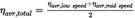
where:
ηavr,low speed
=
average efficiency for low speed
ηavr,mid speed
=
average efficiency for mid speed
ηavr,high speed
=
average efficiency for high speed
ηavr,total
=
simplified averaged efficiency for axle
6.2.5If the conformity of the certified CO2 emissions and fuel consumption related properties assessment is performed in accordance with 6.1. c), the drag torque of the parent axle of the family to which the tested axle belongs shall be determined during the certification. This can be done prior to the run-in procedure or after the run-in procedure according to paragraph 3.1 or by linear extrapolation of all the torque map values for each speed step downwards to 0 Nm.U.K.
6.3Determination of drag torqueU.K.
6.3.1For determination of the drag torque of an axle a simplified test set-up with one electric machine and one torque sensor on the input side is required.U.K.
6.3.2The test conditions according to paragraph 4.1 shall apply. The uncertainty calculation regarding torque may be omitted.U.K.
6.3.3The drag torque shall be measured in the speed range of the approved type according to paragraph 4.3.4 under consideration of the speed steps according to 4.3.5.U.K.
6.4.Conformity of the certified CO2 emissions and fuel consumption related properties test assessmentU.K.
6.4.1A conformity of the certified CO2 emissions and fuel consumption related properties test is passed when one of the following conditions apply:U.K.
(a)
[F1If a torque loss measurement in accordance with points 6.1(a) or (b) is conducted, the average efficiency of the tested axle during conformity of the certified CO 2 emissions and fuel consumption related properties procedure shall not be lower than 1,5 % for SR axles and 2,0 % for all other axles lines below the corresponding average efficiency of the type approved axle.
(b)
If a measurement of drag torque in accordance with point 6.1(c) is conducted, the drag torque of the tested axle during conformity of the certified CO 2 emissions and fuel consumption related properties procedure shall be lower than the corresponding drag torque of the type approved axle or within the tolerance indicated in Table 2.]
Table 2
| Axleline | Tolerances for axles measured in CoP after run-inComparison to Td0 | Tolerances for axles measured in CoP without run inComparison to Td0 | ||||||
|---|---|---|---|---|---|---|---|---|
| for i | tolerance Td0_input [Nm] | for i | tolerance Td0_input [Nm] | for i | tolerance Td0_input Nm] | for i | tolerance Td0_input [Nm] | |
| SR | ≤ 3 | 15 | > 3 | 12 | ≤ 3 | 25 | > 3 | 20 |
| SRT | ≤ 3 | 16 | > 3 | 13 | ≤ 3 | 27 | > 3 | 21 |
| SP | ≤ 6 | 11 | > 6 | 10 | ≤ 6 | 18 | > 6 | 16 |
| HR | ≤ 7 | 10 | > 7 | 9 | ≤ 7 | 16 | > 7 | 15 |
| HRT | ≤ 7 | 11 | > 7 | 10 | ≤ 7 | 18 | > 7 | 16 |
i
=
gear ratio.
Appendix 1
MODEL OF A CERTIFICATE OF A COMPONENT, SEPARATE TECHNICAL UNIT OR SYSTEM U.K.
Maximum format: A4 (210 × 297 mm)U.K.
CERTIFICATE ON CO2 EMISSIONS AND FUEL CONSUMPTION RELATED PROPERTIES OF AN AXLE FAMILY U.K.
of a certificate on CO2 emission and fuel consumption related properties of an axle family in accordance with Commission Regulation (EU) 2017/2400.
Commission Regulation (EU) 2017/2400 as last amended by …
Certification number:
Hash:
Reason for extension:
SECTION IU.K.
0.1Make (trade name of manufacturer):U.K.
0.2Type:U.K.
0.3Means of identification of type, if marked on the axleU.K.
0.3.1Location of the marking:U.K.
0.4Name and address of manufacturer:U.K.
0.5In the case of components and separate technical units, location and method of affixing of the EC certification mark:U.K.
0.6Name(s) and address(es) of assembly plant(s):U.K.
0.7Name and address of the manufacturer's representative (if any)U.K.
SECTION IIU.K.
1.Additional information (where applicable): see AddendumU.K.
2.Approval authority responsible for carrying out the tests:U.K.
3.Date of test reportU.K.
4.Number of test reportU.K.
5.Remarks (if any): see AddendumU.K.
6.PlaceU.K.
7.DateU.K.
8.SignatureU.K.
Attachments:
1.
Information document
2.
Test report
Appendix 2
Axle information document U.K.
| Information document no.: | Issue: Date of issue: Date of Amendment: |
pursuant to …
[F1Axle type/family (if applicable):]
…
0.GENERALU.K.
0.1Name and address of manufacturerU.K.
0.2Make (trade name of manufacturer):U.K.
0.3Axle type:U.K.
0.4Axle family (if applicable):U.K.
0.5Axle type as separate technical unit / Axle family as separate technical unitU.K.
0.6Commercial name(s) (if available):U.K.
0.7Means of identification of type, if marked on the axle:U.K.
0.8In the case of components and separate technical units, location and method of affixing of the certification mark:U.K.
0.9Name(s) and address(es) of assembly plant(s):U.K.
0.10Name and address of the manufacturer's representative:U.K.
PART 1U.K. ESSENTIAL CHARACTERISTICS OF THE (PARENT) AXLE AND THE AXLE TYPES WITHIN AN AXLE FAMILY
| Parent axle | Family member | ||||
| or axle type | #1 | #2 | #3 | ||
F30.0GENERALU.K.
F30.1. . . . . . . . . . . . . . . . . . . . . . . . . . . . . . . .U.K.
F30.2. . . . . . . . . . . . . . . . . . . . . . . . . . . . . . . .U.K.
F30.3. . . . . . . . . . . . . . . . . . . . . . . . . . . . . . . .U.K.
F30.4. . . . . . . . . . . . . . . . . . . . . . . . . . . . . . . .U.K.
F30.5. . . . . . . . . . . . . . . . . . . . . . . . . . . . . . . .U.K.
F30.6. . . . . . . . . . . . . . . . . . . . . . . . . . . . . . . .U.K.
F30.7. . . . . . . . . . . . . . . . . . . . . . . . . . . . . . . .U.K.
F30.8.. . . . . . . . . . . . . . . . . . . . . . . . . . . . . . . .U.K.
F30.9.. . . . . . . . . . . . . . . . . . . . . . . . . . . . . . . .U.K.
Textual Amendments
1.0SPECIFIC AXLE INFORMATIONU.K.
| 1.1 | Axle line (SR, HR, SP, SRT, HRT) | … | … | … | … | ||
| 1.2 | Axle gear ratio | … | … | … | … | ||
| 1.3 | Axle housing (number/ID/drawing) | … | … | … | … | ||
| 1.4 | Gear specifications | … | … | … | |||
| 1.4.1 | Crown wheel diameter; [mm] | … | … | ||||
| 1.4.2 | Vertical offset pinion/crown wheel; [mm] | … |
1.4.3Pinion angle with respect to horizontal plane; [°]U.K.
1.4.4For portal axles only:U.K.
Angle between pinion axle and crown wheel axle; [°]
1.4.5Teeth number of pinionU.K.
1.4.6Teeth number of crown gearU.K.
1.4.7Horizontal offset of pinion; [mm]U.K.
1.4.8Horizontal offset of crown wheel; [mm]U.K.
1.5Oil volume; [cm3]U.K.
1.6Oil level; [mm]U.K.
1.7Oil specificationU.K.
1.8Bearing type (number/ID/drawing)U.K.
1.9Seal type (main diameter, lip number); [mm]U.K.
1.10.Wheel ends (number/ID/drawing)U.K.
1.10.1Bearing type (number/ID/drawing)U.K.
1.10.2Seal type (main diameter, lip number); [mm]U.K.
1.10.3Grease typeU.K.
1.11.Number of planetary/spur gearsU.K.
1.12Smallest width of planetary/spur gears; [mm]U.K.
1.13Gear ratio of hub reductionU.K.
LIST OF ATTACHMENTSU.K.
| No.: | Description: | Date of issue: |
|---|---|---|
| 1 | … | … |
| 2 | … |
Appendix 3
Calculation of the standard torque loss U.K.
The standard torque losses for axles are shown in Table 1. The standard table values consist of the sum of a generic constant efficiency value covering the load dependent losses and a generic basic drag torque loss to cover the drag losses at low loads.
Tandem axles shall be calculated using a combined efficiency for an axle including drive-thru (SRT, HRT) plus the matching single axle (SR, HR).
Table 1
Generic efficiency and drag loss
| Basic function | Generic efficiencyη | Drag torque(wheel side)Td0 = T0 + T1 * igear |
|---|---|---|
| Single reduction axle (SR) | 0,98 | T0 = 70 Nm T1 = 20 Nm |
| Single reduction tandem axle (SRT) / single portal axle (SP) | 0,96 | T0 = 80 Nm T1 = 20 Nm |
| Hub reduction axle (HR) | 0,97 | T0 = 70 Nm T1 = 20 Nm |
| Hub reduction tandem axle (HRT) | 0,95 | T0 = 90 Nm T1 = 20 Nm |
The basic drag torque (wheel side) Td0 is calculated by
Td0 = T0 + T1 * igear
using the values from Table 1.
The standard torque loss Tloss,std on the wheel side of the axle is calculated by

where:
Tloss,std
=
Standard torque loss at the wheel side [Nm]
Td0
=
Basis drag torque over the complete speed range [Nm]
igear
=
Axle gear ratio [-]
η
=
Generic efficiency for load dependent losses [-]
Tout
=
Output torque [Nm]
Appendix 4
Family Concept U.K.
1.The applicant for a certificate shall submit to the approval authority an application for a certificate for an axle family based on the family criteria as indicated in paragraph 3.U.K.
An axle family is characterized by design and performance parameters. These shall be common to all axles within the family. The axle manufacturer may decide which axle belongs to an axle family, as long as the family criteria of paragraph 4 are respected. In addition to the parameters listed in paragraph 4, the axle manufacturer may introduce additional criteria allowing the definition of families of more restricted size. These parameters are not necessarily parameters that have an influence on the level of performance. The axle family shall be approved by the approval authority. The manufacturer shall provide to the approval authority the appropriate information relating to the performance of the members of the axle family.
2.Special casesU.K.
In some cases there may be interaction between parameters. This shall be taken into consideration to ensure that only axles with similar characteristics are included within the same axle family. These cases shall be identified by the manufacturer and notified to the approval authority. It shall then be taken into account as a criterion for creating a new axle family.
In case of parameters, which are not listed in paragraph 3 and which have a strong influence on the level of performance, this parameters shall be identified by the manufacturer on the basis of good engineering practice, and shall be notified to the approval authority.
3.Parameters defining an axle family:U.K.
3.1Axle categoryU.K.
(a)
Single reduction axle (SR)
(b)
Hub reduction axle (HR)
(c)
Single portal axle (SP)
(d)
Single reduction tandem axle (SRT)
(e)
Hub reduction tandem axle (HRT)
(f)
Same inner axle housing geometry between differential bearings and horizontal plane of centre of pinion shaft according to drawing specification (Exception for single portal axles (SP)). Geometry changes due to an optional integration of a differential lock are permitted within the same axle family. In case of mirror inverted axle casings of axles, the mirror inverted axles can be combined in the same axle family as the origin axles, under the premise, that the bevel gear sets are adapted to the other running direction (change of spiral direction).
(g)
[F1Crown wheel diameter (+ 1,5 %/– 8 % ref. to the largest drawing diameter)]
(h)
Vertical hypoid offset pinion/crown wheel within ± 2 mm
(i)
In case of single portal axles (SP): Pinion angle with respect to horizontal plane within ± 5°
(j)
In case of single portal axles (SP): Angle between pinion axle and crown wheel axle within ± 3,5°
(k)
In case of hub reduction and single portal axles (HR, HRT, FHR, SP): Same number of planetary gear and spur wheels
(l)
[F1Gear ratio of every gear step within an axle in a range of 2, as long as only one gear set is changed]
(m)
Oil level within ± 10 mm or oil volume ± 0,5 litre referring to drawing specification and the installation position in the vehicle
(n)
Same oil type viscosity grade (recommended factory fill)
(o)
For all bearings: same bearing rolling/sliding circle diameter (inner/outer) and width within ± 2 mm ref. to drawing
(p)
[F3. . . . .]
4.Choice of the parent axle:U.K.
4.1The parent axle within an axle family is determined as the axle with the highest axle ratio. In case of more than two axles having the same axle ratio, the manufacturer shall provide an analysis in order to determine the worst-case axle as parent axle.U.K.
4.2.The approval authority may conclude that the worst-case torque loss of the family can best be characterized by testing additional axles. In this case, the axle manufacturer shall submit the appropriate information to determine the axle within the family likely to have the highest torque loss level.U.K.
4.3.If axles within the family incorporate other features which may be considered to affect the torque losses, these features shall also be identified and taken into account in the selection of the parent axle.U.K.
Appendix 5
Markings and numbering U.K.
1.MarkingsU.K.
In the case of an axle being type approved accordant to this Annex, the axle shall bear:
1.1.
[F1The manufacturer's name or trade mark]
1.2
The make and identifying type indication as recorded in the information referred to in paragraph 0.2 and 0.3 of Appendix 2 to this Annex
1.3
The certification mark as a rectangle surrounding the lower-case letter ‘e’ followed by the distinguishing number of the Member State which has granted the certificate:
1 for Germany;
2 for France;
3 for Italy;
4 for the Netherlands;
5 for Sweden;
6 for Belgium;
7 for Hungary;
8 for the Czech Republic;
9 for Spain;
11 for the United Kingdom;
12 for Austria;
13 for Luxembourg;
17 for Finland;
18 for Denmark;
19 for Romania;
20 for Poland;
21 for Portugal;
23 for Greece;
24 for Ireland;
25 for Croatia;
26 for Slovenia;
27 for Slovakia;
29 for Estonia;
32 for Latvia;
34 for Bulgaria;
36 for Lithuania;
49 for Cyprus;
50 for Malta
1.4The certification mark shall also include in the vicinity of the rectangle the ‘base certification number’ as specified for Section 4 of the type-approval number set out in Annex VII to Directive 2007/46/EC, preceded by the two figures indicating the sequence number assigned to the latest technical amendment to this Regulation and by a character ‘L’ indicating that the certificate has been granted for an axle.U.K.
For this Regulation, the sequence number shall be 00.
1.4.1Example and dimensions of the certification markU.K.

The above certification mark affixed to an axle shows that the type concerned has been approved in Poland (e20), pursuant to this Regulation. The first two digits (00) are indicating the sequence number assigned to the latest technical amendment to this Regulation. The following letter indicates that the certificate was granted for an axle (L). The last four digits (0004) are those allocated by the type-approval authority to the axle as the base certification number.
1.5Upon request of the applicant for a certificate and after prior agreement with the type-approval authority other type sizes than indicated in 1.4.1 may be used. Those other type sizes shall remain clearly legible.U.K.
1.6The markings, labels, plates or stickers must be durable for the useful life of the axle and must be clearly legible and indelible. The manufacturer shall ensure that the markings, labels, plates or sticker cannot be removed without destroying or defacing them.U.K.
1.7The certification number shall be visible when the axle is installed on the vehicle and shall be affixed to a part necessary for normal operation and not normally requiring replacement during component life.U.K.
2.Numbering:U.K.
[F12.1. Certification number for axles shall comprise the following: U.K.
eX*YYYY/YYYY*ZZZZ/ZZZZ*L*0000*00
| Section 1 | Section 2 | Section 3 | Additional letter to Section 3 | Section 4 | Section 5 |
|---|---|---|---|---|---|
| Indication of country issuing the certificate | HDV CO 2 certification Regulation (2017/2400) | Latest amending Regulation (ZZZZ/ZZZZ) | L = Axle | Base certification number 0000 | Extension 00] |
Appendix 6
Input parameters for the simulation tool U.K.
IntroductionU.K.
This Appendix describes the list of parameters to be provided by the component manufacturer as input to the simulation tool. The applicable XML schema as well as example data are available at the dedicated electronic distribution platform.
DefinitionsU.K.
Unique identifier as used in the simulation tool for a specific input parameter or set of input data]
(2) ‘Type’:
Data type of the parameter
string …
sequence of characters in ISO8859-1 encoding
token …
sequence of characters in ISO8859-1 encoding, no leading/trailing whitespace
date …
date and time in UTC time in the format: YYYY-MM-DD T HH:MM:SS Z with italic letters denoting fixed characters e.g. ‘2002-05-30T09:30:10Z’
integer …
value with an integral data type, no leading zeros, e.g. ‘1800’
double, X …
fractional number with exactly X digits after the decimal sign (‘.’) and no leading zeros e.g. for ‘double, 2’: ‘2345.67’; for ‘double, 4’: ‘45.6780’
(3) ‘Unit’ …
physical unit of the parameter
Set of input parametersU.K.
Table 1
Input parameters ‘Axlegear/General’
| Parameter name | Param ID | Type | Unit | Description/Reference |
|---|---|---|---|---|
| Manufacturer | P215 | token | [-] | |
| Model | P216 | token | [-] | |
| [F1CertificationNumber | P217 | token | [-] | ] |
| Date | P218 | dateTime | [-] | Date and time when the component-hash is created |
| AppVersion | P219 | token | [-] | |
| LineType | P253 | string | [-] | Allowed values: ‘Single reduction axle’, ‘Single portal axle’, ‘Hub reduction axle’, ‘Single reduction tandem axle’, ‘Hub reduction tandem axle’ |
| Ratio | P150 | double, 3 | [-] | |
| CertificationMethod | P256 | string | [-] | Allowed values: ‘Measured’, ‘Standard values’ |
Table 2
Input parameters ‘Axlegear/LossMap’ for each grid point in the loss map
| Parameter name | Param ID | Type | Unit | Description/Reference |
|---|---|---|---|---|
| InputSpeed | P151 | double, 2 | [1/min] | |
| InputTorque | P152 | double, 2 | [Nm] | |
| TorqueLoss | P153 | double, 2 | [Nm] |
Options/Help
Print Options
PrintThe Whole Regulation
PrintThis Annex only
You have chosen to open the Whole Regulation
The Whole Regulation you have selected contains over 200 provisions and might take some time to download. You may also experience some issues with your browser, such as an alert box that a script is taking a long time to run.
Would you like to continue?
You have chosen to open Schedules only
Y Rhestrau you have selected contains over 200 provisions and might take some time to download. You may also experience some issues with your browser, such as an alert box that a script is taking a long time to run.
Would you like to continue?
Mae deddfwriaeth ar gael mewn fersiynau gwahanol:
Y Diweddaraf sydd Ar Gael (diwygiedig):Y fersiwn ddiweddaraf sydd ar gael o’r ddeddfwriaeth yn cynnwys newidiadau a wnaed gan ddeddfwriaeth ddilynol ac wedi eu gweithredu gan ein tîm golygyddol. Gellir gweld y newidiadau nad ydym wedi eu gweithredu i’r testun eto yn yr ardal ‘Newidiadau i Ddeddfwriaeth’.
Gwreiddiol (Fel y’i mabwysiadwyd gan yr UE): Mae'r wreiddiol version of the legislation as it stood when it was first adopted in the EU. No changes have been applied to the text.
Gweler y wybodaeth ychwanegol ochr yn ochr â’r cynnwys
Rhychwant ddaearyddol: Indicates the geographical area that this provision applies to. For further information see ‘Frequently Asked Questions’.
Dangos Llinell Amser Newidiadau: See how this legislation has or could change over time. Turning this feature on will show extra navigation options to go to these specific points in time. Return to the latest available version by using the controls above in the What Version box.
Dewisiadau Agor
Dewisiadau gwahanol i agor deddfwriaeth er mwyn gweld rhagor o gynnwys ar y sgrin ar yr un pryd
Rhagor o Adnoddau
Gallwch wneud defnydd o ddogfennau atodol hanfodol a gwybodaeth ar gyfer yr eitem ddeddfwriaeth o’r tab hwn. Yn ddibynnol ar yr eitem ddeddfwriaeth sydd i’w gweld, gallai hyn gynnwys:
- y PDF print gwreiddiol y fel adopted version that was used for the EU Official Journal
- rhestr o newidiadau a wnaed gan a/neu yn effeithio ar yr eitem hon o ddeddfwriaeth
- pob fformat o’r holl ddogfennau cysylltiedig
- slipiau cywiro
- dolenni i ddeddfwriaeth gysylltiedig ac adnoddau gwybodaeth eraill
Llinell Amser Newidiadau
Mae’r llinell amser yma yn dangos y fersiynau gwahanol a gymerwyd o EUR-Lex yn ogystal ag unrhyw fersiynau dilynol a grëwyd ar ôl y diwrnod ymadael o ganlyniad i newidiadau a wnaed gan ddeddfwriaeth y Deyrnas Unedig.
Cymerir dyddiadau fersiynau’r UE o ddyddiadau’r dogfennau ar EUR-Lex ac efallai na fyddant yn cyfateb â’r adeg pan ddaeth y newidiadau i rym ar gyfer y ddogfen.
Ar gyfer unrhyw fersiynau a grëwyd ar ôl y diwrnod ymadael o ganlyniad i newidiadau a wnaed gan ddeddfwriaeth y Deyrnas Unedig, bydd y dyddiad yn cyd-fynd â’r dyddiad cynharaf y daeth y newid (e.e. ychwanegiad, diddymiad neu gyfnewidiad) a weithredwyd i rym. Am ragor o wybodaeth gweler ein canllaw i ddeddfwriaeth ddiwygiedig ar Ddeall Deddfwriaeth.
Rhagor o Adnoddau
Defnyddiwch y ddewislen hon i agor dogfennau hanfodol sy’n cyd-fynd â’r ddeddfwriaeth a gwybodaeth am yr eitem hon o ddeddfwriaeth. Gan ddibynnu ar yr eitem o ddeddfwriaeth sy’n cael ei gweld gall hyn gynnwys:
- y PDF print gwreiddiol y fel adopted fersiwn a ddefnyddiwyd am y copi print
- slipiau cywiro
liciwch ‘Gweld Mwy’ neu ddewis ‘Rhagor o Adnoddau’ am wybodaeth ychwanegol gan gynnwys
- rhestr o newidiadau a wnaed gan a/neu yn effeithio ar yr eitem hon o ddeddfwriaeth
- manylion rhoi grym a newid cyffredinol
- pob fformat o’r holl ddogfennau cysylltiedig
- dolenni i ddeddfwriaeth gysylltiedig ac adnoddau gwybodaeth eraill
 Mae’r holl gynnwys ar gael dan Drwydded Llywodraeth Agored v3.0 ac eithrio ble nodir yn wahanol. Yn ychwanegol mae’r safle hwn â chynnwys sy’n deillio o EUR-Lex, a ailddefnyddiwyd dan delerau Penderfyniad y Comisiwn 2011/833/EU ar ailddefnyddio dogfennau o sefydliadau’r UE. Am ragor o wybodaeth gweler ddatganiad cyhoeddus Swyddfa Gyhoeddiadau’r UE ar ailddefnyddio.