
[F1ANNEX VIII U.K. DESCRIPTION OF MANIKIN
Textual Amendments
| 1. | SPECIFICATIONS OF THE MANIKIN | ||||
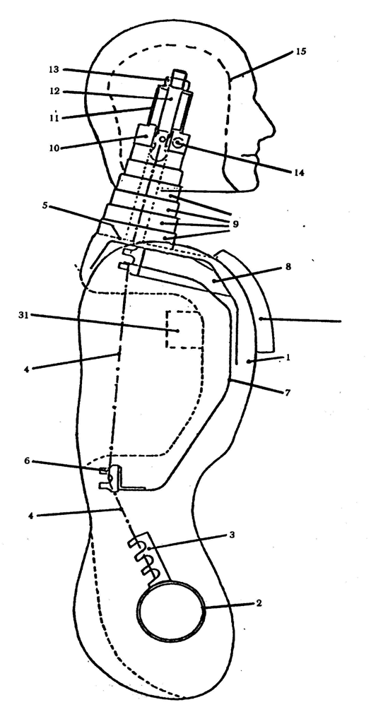
| 1.1. | General The main characteristics of the manikin are indicated in the following figures and tables: Figure 1 : side view of head, neck and torso; Figure 2 : front view of head, neck and torso; Figure 3 : side view of hip, thighs and lower leg; Figure 4 : front view of hip, thighs and lower leg; Figure 5 : principal dimensions; Figure 6 : manikin in sitting position, showing:
table 1 : mass of head, neck, torso, thigh and lower leg table 2 : references, names, materials and principal dimensions of the components of the manikin. | ||||
| 1.2. | Description of the manikin | ||||
| 1.2.1. | Lower leg structure (see Figures 3 and 4) The lower leg structure consists of three components:
The knee tube has two lugs which limit the movement of the lower leg in relation to the thigh. The lower leg can rotate rearwards about 120 o from the straight position. | ||||
| 1.2.2. | Thigh structure (see Figures 3 and 4) The thigh structure consists of three components:
Movement of the knee is limited by two cut-outs in the knee tube (22) which engage with the lugs of the leg. | ||||
| 1.2.3. | Torso structure (see Figures 1 and 2) The torso structure consists of the following components:
| ||||
| 1.2.4. | Neck (see Figures 1 and 2) The neck consists of seven polyurethane discs (9). The degree of stiffness of the neck can be adjusted by means of a chain tensioner. | ||||
| 1.2.5. | Head (see Figures 1 and 2) The head (15) is hollow; the polyurethane is reinforced by steel bands (17). The chain tensioner which enables the neck to be adjusted consists of a poiyamide block (10), a tubular spacer (11) and a tensioning component (12 and 13). The head can rotate at the joint berween the first and second cervical vertebrae (the atlas-axis joint), which consists of an adjuster assembly (14 and 18), a spacer (16) and a polyamide block (10). | ||||
| 1.2.6. | Knee joint (see Figure 4) The lower leg and thighs are connected by a tube (27) and a tensioner (28). | ||||
| 1.2.7. | Hip joint (see Figure 4) The thighs and torso are connected by a tube (23), friction plates (24) and a tensioner (25). | ||||
| 1.2.8. | Polyurethane
| ||||
| 1.2.9. | Overall The manikin is covered by a special overall. | ||||
| 2. | CORRECTION OF THE MASS In order to calibrate the manikin to certain values and its total mass, the mass distribution must be adjusted by means of six correction weights of 1 kg each which can be fitted to the hip joint. Six other polyurethane weights of 1 kg each can be fitted to the back of the torso. | ||||
| 3. | CUSHION A cushion shall be positioned between the chest of the manikin and the overall. This cushion must be made of polyethylene foam complying with the following specification:
It shall be replaceable. | ||||
| 4. | ADJUSTMENT OF THE JOINTS | ||||
| 4.1. | General In order to achieve reproducible results, it is necessary to specify and control the friction at each joint. | ||||
| 4.2. | Knee joint: tighten the knee joint; set the thigh and lower leg vertical; rotate the lower leg through 30 o ; gradually slacken the tensioner until the lower leg starts to fall under its own weight; lock the tensioner in this position. | ||||
| 4.3. | Hip joints: increase the rigidity of the hip ioints for the purposes of adjustment; place the thighs in a horizontal position and the torso in a vertical position; rotate the torso forwards until it forms an angle of 60 o with the thighs; gradually slacken the tensioner until the torso starts to fall under its own weight; lock the tensioner in this position. | ||||
| 4.4. | Atlas-axis joint: adjust the atlas-axis joint so that it just resists its own weight in the fore and aft directions. | ||||
| 4.5. | Neck: the neck can be adjusted by means of the chain tensioner (13); when the neck is adjusted, the upper end of the tensioner shall be displaced between 40 and 60 mm when subjected to a horizontal load of 10 daN. |
TABLE 1
| Components of manikin | Mass in kilograms |
|---|---|
| Head and neck | 4,6 ± 0,3 |
| Torso and arms | 40,3 ± 1,0 |
| Thighs | 16,2 ± 0,5 |
| Lower leg and foot | 9,0 ± 0,5 |
| Total mass including correction weights | 75,5 ± 1,0 |
TABLE 2
| Reference No | Name | Material | Dimensions |
|---|---|---|---|
| 1 | Body | polyurethane | - |
| 2 | Hip tube | steel | 76 × 70 × 100 mm |
| 3 | Chain attachments | steel | 25 × 10 × 70 mm |
| 4 | Roller chain | steel | ¾ mm |
| 5 | Shoulder plane | polyurethane | - |
| 6 | Ribs (rolled section) | steel | 30 × 30 × 3 × 250 mm |
| 7 | Ribs | perforated steelplate | 400 × 85 × 1,5 mm |
| 8 | Sternum | perforated steelplate | 250 × 90 × 1,5 mm |
| 9 | Discs (6) | polyurethane | ∅ 90 × 20 mm, ∅ 80 × 20 mm ∅ 75 × 20 mm; ∅ 70 × 20 mm ∅ 65 × 20 mm, ∅ 60 × 20 mm |
| 10 | Block | polyamide | 60 × 60 × 25 mm |
| 11 | Tubular spacer | steel | 40 × 40 × 2 × 50 mm |
| 12 | Tensioning bolt | steel | M16 × 90 mm |
| 13 | Tensioner nut | steel | M16 |
| 14 | Tensioner for atlas-axis joint | steel | ∅ 12 × 130 mm (M12) |
| 15 | Head | polyurethane | - |
| 16 | Tubular spacer | steel | ∅ 18 × 13 × 17 mm |
| 17 | Reinforcement plate | steel | 30 × 3 × 500 mm |
| 18 | Tensioner nut | steel | M12 |
| 19 | Thighs | polyurethane | - |
| 20 | Hip tube | steel | 76 × 70 × 80 mm |
| 21 | Thigh bar | steel | 30 × 30 × 440 mm |
| 22 | Knee tube | steel | 52 × 46 × 40 mm |
| 23 | Hip connecting tube | steel | 70 × 64 × 250 mm |
| 24 | Friction plates (4) | steel | 160 × 75 × 1 mm |
| 25 | Tensioner assembly | steel | M12 × 320 mm plates and nuts |
| 26 | Knee tube | steel | 52 × 46 × 160 mm |
| 27 | Knee connecting tube | steel | 44 × 39 × 190 mm |
| 28 | Tensioner plate | steel | ∅ 70 × 4 mm |
| 29 | Shin tube | steel | 50 × 50 × 2 × 460 mm |
| 30 | Sole plate | steel | 100 × 170 × 3 mm |
| 31 | Torso correction weights (6) | polyurethane | 1 kg each |
| 32 | Cushion | polyurethane foam | 350 × 250 × 25 mm |
| 33 | Overall | cotton and polyamide straps | |
| 34 | Hip joint correction weights (6) | steel | mass 1 kg each |


Manikin seated in position shown in Annex VII, Figure 1.
=
centre of gravity,
=
torso measurement point (located at the front on the centre line of the manikin),
=
pelvis measurement point (located at the back on the centre line of the manikin).]