- Latest available (Revised)
- Point in Time (01/05/2004)
- Original (As adopted by EU)
Council Directive of 28 June 1977 on the approximation of the laws of the Member States relating to safety belts and restraint systems of motor vehicles (77/541/EEC) (repealed)
You are here:

What Version
Advanced Features
- Show Geographical Extent(e.g. England, Wales, Scotland and Northern Ireland)
- Show Timeline of Changes
More Resources
Revised version PDFs
- Revised 01/11/20140.44 MB
- Revised 01/07/20131.59 MB
- Revised 01/01/20070.76 MB
- Revised 20/10/20050.79 MB
- Revised 01/05/20040.79 MB
- Revised 16/03/20000.77 MB
- Revised 06/08/19960.79 MB
- Revised 01/01/19950.56 MB
- Revised 06/12/19900.57 MB
- Revised 29/06/19870.49 MB
- Revised 01/01/19860.49 MB
- Revised 20/04/19820.49 MB
- Revised 24/07/19810.53 MB
- Revised 01/01/19810.52 MB
Legislation originating from the EU
When the UK left the EU, legislation.gov.uk published EU legislation that had been published by the EU up to IP completion day (31 December 2020 11.00 p.m.). On legislation.gov.uk, these items of legislation are kept up-to-date with any amendments made by the UK since then.


This item of legislation originated from the EU
Legislation.gov.uk publishes the UK version. EUR-Lex publishes the EU version. The EU Exit Web Archive holds a snapshot of EUR-Lex’s version from IP completion day (31 December 2020 11.00 p.m.).
Changes over time for: ANNEX VIII
Version Superseded: 20/10/2005
Status:
EU Directives are published on this site to aid cross referencing from UK legislation. Since IP completion day (31 December 2020 11.00 p.m.) no amendments have been applied to this version.
[F1ANNEX VIII U.K. DESCRIPTION OF MANIKIN
Textual Amendments
| 1. | SPECIFICATIONS OF THE MANIKIN | ||||
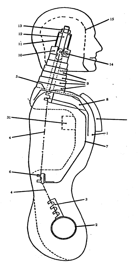
| 1.1. | General The main characteristics of the manikin are indicated in the following figures and tables: Figure 1 : side view of head, neck and torso; Figure 2 : front view of head, neck and torso; Figure 3 : side view of hip, thighs and lower leg; Figure 4 : front view of hip, thighs and lower leg; Figure 5 : principal dimensions; Figure 6 : manikin in sitting position, showing:
table 1 : mass of head, neck, torso, thigh and lower leg table 2 : references, names, materials and principal dimensions of the components of the manikin. | ||||
| 1.2. | Description of the manikin | ||||
| 1.2.1. | Lower leg structure (see Figures 3 and 4) The lower leg structure consists of three components:
The knee tube has two lugs which limit the movement of the lower leg in relation to the thigh. The lower leg can rotate rearwards about 120 o from the straight position. | ||||
| 1.2.2. | Thigh structure (see Figures 3 and 4) The thigh structure consists of three components:
Movement of the knee is limited by two cut-outs in the knee tube (22) which engage with the lugs of the leg. | ||||
| 1.2.3. | Torso structure (see Figures 1 and 2) The torso structure consists of the following components:
| ||||
| 1.2.4. | Neck (see Figures 1 and 2) The neck consists of seven polyurethane discs (9). The degree of stiffness of the neck can be adjusted by means of a chain tensioner. | ||||
| 1.2.5. | Head (see Figures 1 and 2) The head (15) is hollow; the polyurethane is reinforced by steel bands (17). The chain tensioner which enables the neck to be adjusted consists of a poiyamide block (10), a tubular spacer (11) and a tensioning component (12 and 13). The head can rotate at the joint berween the first and second cervical vertebrae (the atlas-axis joint), which consists of an adjuster assembly (14 and 18), a spacer (16) and a polyamide block (10). | ||||
| 1.2.6. | Knee joint (see Figure 4) The lower leg and thighs are connected by a tube (27) and a tensioner (28). | ||||
| 1.2.7. | Hip joint (see Figure 4) The thighs and torso are connected by a tube (23), friction plates (24) and a tensioner (25). | ||||
| 1.2.8. | Polyurethane
| ||||
| 1.2.9. | Overall The manikin is covered by a special overall. | ||||
| 2. | CORRECTION OF THE MASS In order to calibrate the manikin to certain values and its total mass, the mass distribution must be adjusted by means of six correction weights of 1 kg each which can be fitted to the hip joint. Six other polyurethane weights of 1 kg each can be fitted to the back of the torso. | ||||
| 3. | CUSHION A cushion shall be positioned between the chest of the manikin and the overall. This cushion must be made of polyethylene foam complying with the following specification:
It shall be replaceable. | ||||
| 4. | ADJUSTMENT OF THE JOINTS | ||||
| 4.1. | General In order to achieve reproducible results, it is necessary to specify and control the friction at each joint. | ||||
| 4.2. | Knee joint: tighten the knee joint; set the thigh and lower leg vertical; rotate the lower leg through 30 o ; gradually slacken the tensioner until the lower leg starts to fall under its own weight; lock the tensioner in this position. | ||||
| 4.3. | Hip joints: increase the rigidity of the hip ioints for the purposes of adjustment; place the thighs in a horizontal position and the torso in a vertical position; rotate the torso forwards until it forms an angle of 60 o with the thighs; gradually slacken the tensioner until the torso starts to fall under its own weight; lock the tensioner in this position. | ||||
| 4.4. | Atlas-axis joint: adjust the atlas-axis joint so that it just resists its own weight in the fore and aft directions. | ||||
| 4.5. | Neck: the neck can be adjusted by means of the chain tensioner (13); when the neck is adjusted, the upper end of the tensioner shall be displaced between 40 and 60 mm when subjected to a horizontal load of 10 daN. |
TABLE 1
| Components of manikin | Mass in kilograms |
|---|---|
| Head and neck | 4,6 ± 0,3 |
| Torso and arms | 40,3 ± 1,0 |
| Thighs | 16,2 ± 0,5 |
| Lower leg and foot | 9,0 ± 0,5 |
| Total mass including correction weights | 75,5 ± 1,0 |
TABLE 2
| Reference No | Name | Material | Dimensions |
|---|---|---|---|
| 1 | Body | polyurethane | - |
| 2 | Hip tube | steel | 76 × 70 × 100 mm |
| 3 | Chain attachments | steel | 25 × 10 × 70 mm |
| 4 | Roller chain | steel | ¾ mm |
| 5 | Shoulder plane | polyurethane | - |
| 6 | Ribs (rolled section) | steel | 30 × 30 × 3 × 250 mm |
| 7 | Ribs | perforated steelplate | 400 × 85 × 1,5 mm |
| 8 | Sternum | perforated steelplate | 250 × 90 × 1,5 mm |
| 9 | Discs (6) | polyurethane | ∅ 90 × 20 mm, ∅ 80 × 20 mm ∅ 75 × 20 mm; ∅ 70 × 20 mm ∅ 65 × 20 mm, ∅ 60 × 20 mm |
| 10 | Block | polyamide | 60 × 60 × 25 mm |
| 11 | Tubular spacer | steel | 40 × 40 × 2 × 50 mm |
| 12 | Tensioning bolt | steel | M16 × 90 mm |
| 13 | Tensioner nut | steel | M16 |
| 14 | Tensioner for atlas-axis joint | steel | ∅ 12 × 130 mm (M12) |
| 15 | Head | polyurethane | - |
| 16 | Tubular spacer | steel | ∅ 18 × 13 × 17 mm |
| 17 | Reinforcement plate | steel | 30 × 3 × 500 mm |
| 18 | Tensioner nut | steel | M12 |
| 19 | Thighs | polyurethane | - |
| 20 | Hip tube | steel | 76 × 70 × 80 mm |
| 21 | Thigh bar | steel | 30 × 30 × 440 mm |
| 22 | Knee tube | steel | 52 × 46 × 40 mm |
| 23 | Hip connecting tube | steel | 70 × 64 × 250 mm |
| 24 | Friction plates (4) | steel | 160 × 75 × 1 mm |
| 25 | Tensioner assembly | steel | M12 × 320 mm plates and nuts |
| 26 | Knee tube | steel | 52 × 46 × 160 mm |
| 27 | Knee connecting tube | steel | 44 × 39 × 190 mm |
| 28 | Tensioner plate | steel | ∅ 70 × 4 mm |
| 29 | Shin tube | steel | 50 × 50 × 2 × 460 mm |
| 30 | Sole plate | steel | 100 × 170 × 3 mm |
| 31 | Torso correction weights (6) | polyurethane | 1 kg each |
| 32 | Cushion | polyurethane foam | 350 × 250 × 25 mm |
| 33 | Overall | cotton and polyamide straps | |
| 34 | Hip joint correction weights (6) | steel | mass 1 kg each |


Manikin seated in position shown in Annex VII, Figure 1.
G
=
centre of gravity,
T
=
torso measurement point (located at the front on the centre line of the manikin),
P
=
pelvis measurement point (located at the back on the centre line of the manikin).]
Options/Help
Print Options
PrintThe Whole Directive
PrintThis Annex only
Legislation is available in different versions:
Latest Available (revised):The latest available updated version of the legislation incorporating changes made by subsequent legislation and applied by our editorial team. Changes we have not yet applied to the text, can be found in the ‘Changes to Legislation’ area.
Original (As adopted by EU): The original version of the legislation as it stood when it was first adopted in the EU. No changes have been applied to the text.
Point in Time: This becomes available after navigating to view revised legislation as it stood at a certain point in time via Advanced Features > Show Timeline of Changes or via a point in time advanced search.
See additional information alongside the content
Geographical Extent: Indicates the geographical area that this provision applies to. For further information see ‘Frequently Asked Questions’.
Show Timeline of Changes: See how this legislation has or could change over time. Turning this feature on will show extra navigation options to go to these specific points in time. Return to the latest available version by using the controls above in the What Version box.
Opening Options
Different options to open legislation in order to view more content on screen at once
More Resources
Access essential accompanying documents and information for this legislation item from this tab. Dependent on the legislation item being viewed this may include:
- the original print PDF of the as adopted version that was used for the EU Official Journal
- lists of changes made by and/or affecting this legislation item
- all formats of all associated documents
- correction slips
- links to related legislation and further information resources
Timeline of Changes
This timeline shows the different versions taken from EUR-Lex before exit day and during the implementation period as well as any subsequent versions created after the implementation period as a result of changes made by UK legislation.
The dates for the EU versions are taken from the document dates on EUR-Lex and may not always coincide with when the changes came into force for the document.
For any versions created after the implementation period as a result of changes made by UK legislation the date will coincide with the earliest date on which the change (e.g an insertion, a repeal or a substitution) that was applied came into force. For further information see our guide to revised legislation on Understanding Legislation.
More Resources
Use this menu to access essential accompanying documents and information for this legislation item. Dependent on the legislation item being viewed this may include:
- the original print PDF of the as adopted version that was used for the print copy
- correction slips
Click 'View More' or select 'More Resources' tab for additional information including:
- lists of changes made by and/or affecting this legislation item
- confers power and blanket amendment details
- all formats of all associated documents
- links to related legislation and further information resources
 All content is available under the Open Government Licence v3.0 except where otherwise stated. This site additionally contains content derived from EUR-Lex, reused under the terms of the Commission Decision 2011/833/EU on the reuse of documents from the EU institutions. For more information see the EUR-Lex public statement on re-use.