- Latest available (Revised)
- Point in Time (07/09/2009)
- Original (As adopted by EU)
Directive 97/24/EC of the European Parliament and of the Council (repealed)Show full title
Directive 97/24/EC of the European Parliament and of the Council of 17 June 1997 on certain components and characteristics of two or three-wheel motor vehicles (repealed)
You are here:
- Directives originating from the EU
- 1997 No. 24
- attachment 10

What Version
Advanced Features
- Show Geographical Extent(e.g. England, Wales, Scotland and Northern Ireland)
- Show Timeline of Changes
More Resources
Revised version PDFs
- Revised 01/01/20160.44 MB
- Revised 11/12/20137.75 MB
- Revised 07/09/20096.33 MB
- Revised 28/11/20063.25 MB
- Revised 08/09/20063.29 MB
- Revised 28/03/20065.31 MB
- Revised 17/05/20054.11 MB
- Revised 10/09/20034.13 MB
- Revised 20/09/20024.04 MB
- Revised 18/08/19974.02 MB
Legislation originating from the EU
When the UK left the EU, legislation.gov.uk published EU legislation that had been published by the EU up to IP completion day (31 December 2020 11.00 p.m.). On legislation.gov.uk, these items of legislation are kept up-to-date with any amendments made by the UK since then.


This item of legislation originated from the EU
Legislation.gov.uk publishes the UK version. EUR-Lex publishes the EU version. The EU Exit Web Archive holds a snapshot of EUR-Lex’s version from IP completion day (31 December 2020 11.00 p.m.).
Changes over time for:
Version Superseded: 01/01/2016
Status:
EU Directives are published on this site to aid cross referencing from UK legislation. Since IP completion day (31 December 2020 11.00 p.m.) no amendments have been applied to this version.
CHAPTER 10
TRAILER COUPLING DEVICES OF TWO OR THREE-WHEEL MOTOR VEHICLES
[X1ANNEX AND APPENDICES
| ANNEX I | Trailer coupling devices of two or three-wheel motor vehicles |
| Appendix 1 | Ball coupling on two or three-wheel motor vehicles |
| Appendix 2 | |
| Appendix 3 | |
| Appendix 4 | Information document in respect of coupling devices for trailers towed by a type of two or three-wheel motor vehicle |
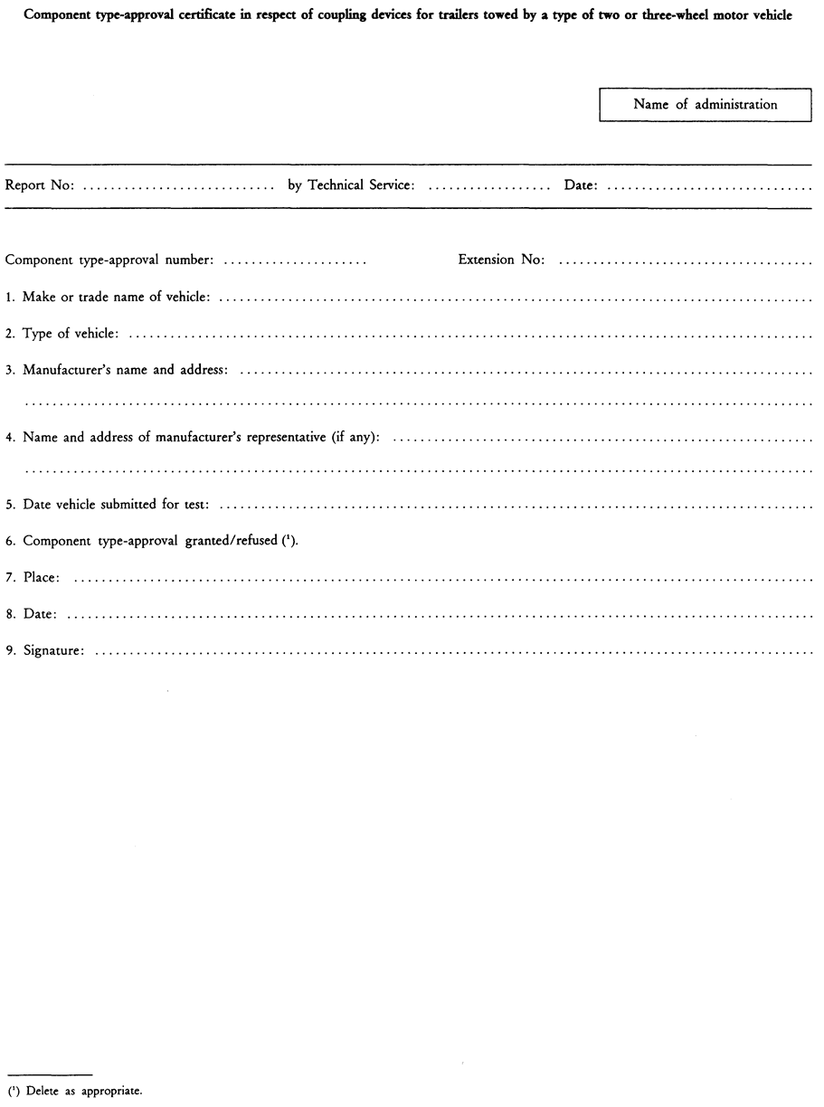
| Appendix 5 | Component type-approval certificate in respect of coupling devices for trailers towed by a type of two or three-wheel motor vehicle] |
ANNEX I
TRAILER COUPLING DEVICES OF TWO OR THREE-WHEEL MOTOR VEHICLES
1.SCOPEU.K.
1.1.This Annex I applies to coupling devices for two and three-wheel motor vehicles and their attachment to these vehicles.U.K.
1.2.This Annex I states the requirements which coupling devices for two and three-wheel motor vehicles must satisfy in order toU.K.
ensure compatibility when combining motor vehicles with different types of trailers;
ensure the safe coupling together of the vehicles under all conditions of use;
ensure safe procedures for coupling and uncoupling.
2.DEFINITIONSU.K.
2.1.‘Coupling devices for motor vehicles’ means all parts and devices fitted to the frames, load-bearing parts of the bodywork and chassis of the vehicles by means of which towing and towed vehicles are connected together.U.K.
They also include fixed or detachable parts for the attachment, adjustment or operation of the abovementioned coupling devices.
2.1.1.‘Coupling balls and towing brackets’ means coupling devices employing a spherical device and brackets on the motor vehicle for connecting to the trailer by means of a coupling head.U.K.
2.1.2.The coupling heads in 2.1.1 are mechanical coupling devices on the drawbar of trailers for connecting to a coupling ball on the motor vehicle.U.K.
3.GENERAL REQUIREMENTSU.K.
3.1.The coupling devices for two and three-wheel motor vehicles must be manufactured and attached in accordance with good engineering practice, and must be safe to operate.U.K.
3.2.The coupling devices must be so designed and manufactured that in normal use, with proper maintenance and the timely replacement of wearing parts, they will continue to function satisfactorily.U.K.
3.3.Every coupling device must be accompanied by installation and operating instructions giving sufficient information for a competent person to install it on the vehicle and operate it properly. The instructions must be in the official language or languages of the Member State in which the coupling device will be offered for sale.U.K.
3.4.The materials that may be used are those for which the properties relevant to the application are laid down in a standard or those for which the properties are given in the application documentation.U.K.
3.5.All parts of the coupling devices whose failure could result in separation of the two vehicles must be made of steel.U.K.
Other materials may be used provided equivalence has been demonstrated by the manufacturer to the satisfaction of the Technical Service.
3.6.All couplings must be designed for positive mechanical engagement, and the closed position must be secured at least once by positive mechanical engagement.U.K.
3.7.In principle coupling balls in accordance with Appendix 1, Figure 1 are to be used on two and three-wheel motor vehicles. In the case of three-wheel vehicles particularly, the coupling type must be chosen and positioned to allow maximum compatibility with a range of trailer types. Devices other than coupling balls may be used, provided the requirements of 3.8 are met and that compatibility and interchangeability of trailers is neither necessary nor possible (dedicated combinations).U.K.
3.8.Coupling devices must be designed in a way to meet the requirements for case of operation, position, mobility and strength according to Sections 3.9, 3.10, 3.11, 4, 5 and 6.U.K.
3.9.The coupling devices must be designed and attached in a way to achieve maximum safety according to good engineering practice; this also applies to the operation of the coupling.U.K.
3.10.Safe coupling and uncoupling of the vehicles must be possible by one person without the use of tools.U.K.
3.11.The operation of detachable coupling devices must be possible easily by hand and without the use of tools.U.K.
4.REQUIREMENTS FOR POSITIONU.K.
4.1.Coupling devices attached to the vehicles must ensure an unhindered and safe operation.U.K.
4.2.Coupling balls attached to the vehicles must correspond to the geometric conditions specified in Appendix 1, Figure 2.U.K.
4.3.The height of the coupling point of a coupling device other than a coupling ball must correspond to the height of the coupling point of the drawbar of the trailer within a range of ± 35 mm, provided the trailer is in a horizontal position.U.K.
4.4.The shape and the dimensions of the towing brackets must correspond to the vehicle manufacturer's requirements with respect to fixing points and any additional mounting devices required.U.K.
4.5.The requirements of the vehicle manufacturer with regard to the type of the coupling device, the permissible mass of the trailer and the permissible static vertical load imposed at the coupling point must be observed.U.K.
4.6.The mounted coupling device must not obscure the visibility of the rear licence plate, otherwise a coupling device which can be dismantled without special tools has to be used.U.K.
5.REQUIREMENTS FOR ARTICULATIONU.K.
5.1.The following articulation must be possible with the coupling device not attached to the vehicle.U.K.
5.1.1.An angle of free vertical pitch of 20o above and below the horizontal centre line at all angles of horizontal rotation up to at least 90o each side of the longitudinal centre line of the device.U.K.
5.1.2.At all angles of horizontal rotation up to 90o each side of the longitudinal centre line of the device there must be an angle of free axial roll each side of the vertical centre line of 25o for three-wheel vehicles or 40o for two-wheel vehicles.U.K.
5.2.At all angles of horizontal rotation the following combinations of articulation must be possible:U.K.
in the case of two-wheel vehicles, except where the device is used with one-wheel trailers which tilt with the two-wheel motor vehicle:
vertical pitch of ± 15o with axial roll of ± 40o,
axial roll of ± 30o with vertical pitch of ± 20o;
in the case of three-wheel vehicles or quadricycles:
vertical pitch of ± 15o with axial roll of ± 25o
axial roll of ± 10o with vertical pitch of ± 20o.
5.3.It must also be possible to couple and uncouple ball couplings when the longitudinal axis of the ball coupling in relation to the centre line of the coupling ball and mounting:U.K.
is horizontally β = 60o right or left
is vertically α = 10o up or down
is axially rotated 10o right or left.
6.REQUIREMENTS FOR STRENGTHU.K.
6.1.A dynamic strength test (endurance test) must be performed.U.K.
6.1.1.The endurance test is performed with an alternating approximately sinusoidal load with a number of load cycles depending on the material. No cracks or fractures or other visible external damage, or any excessive permanent distortion which would be detrimental to the satisfactory operation of the device must occur.U.K.
6.1.2.The loading basis for the dynamic test is the D-value shown below. The static vertical load is taken into consideration in the direction of the test load relative to the horizontal plane, depending on the position of the coupling point and the static vertical load permitted at the coupling point.U.K.

where
T
=
technically permissible maximum mass in tonnes of the towing vehicle
R
=
technically permissible maximum mass in tonnes of the trailer
g
=
acceleration due to gravity (assumed g = 9,81 m/s2)
6.1.3.The characteristic values D and S on which the test is to be based are specified in the manufacturer's EC type-approval application, S being the permitted maximum static vertical load at the coupling point in kg.U.K.
6.2.Test proceduresU.K.
6.2.1.For the dynamic tests the sample must be placed in a suitable rig with a suitable means of force application so that it is not subjected to any additional forces or moments apart from the specified test force. In the case of alternating tests the direction of force application must not deviate by more than ± 1o from the specified direction. To avoid unspecified forces and moments in the sample it may be necessary to have one joint at the point of force application and a second joint an adequate distance away.U.K.
6.2.2.The test frequency must not exceed 35 Hz. The selected frequency must be well separated from resonant frequencies of the test set up including the device being tested. The number of load cycles must be 2 × 10⁶ for coupling devices made of steel. A higher number of load cycles may be required for coupling devices made of other materials. Generally, the crack test is to be performed in accordance with the dye penetration procedure; equivalent other procedures are also permissible.U.K.
6.2.3.The coupling devices on test are normally mounted as rigidly as possible on a test rig in the actual position in which they will be used on the vehicle. The fixing devices must be those specified by the manufacturer or applicant and be those intended for its attachment to the vehicle and/or have identical mechanical characteristics.U.K.
6.2.4.Preferably, couplings have to be tested in original condition as intended for use on the road. At the discretion of the manufacturer and in agreement with the Technical Service, flexible components may be neutralized if this is necessary for the test procedure and if there is no concern about unrealistic influence on the test result.U.K.
Flexible components which are obviously overheated due to this accelerated test procedure may be replaced during the test.
The test loads may be applied by means of special slackfree devices.
The devices submitted for test must be provided with all design details which may have an influence on the strength criteria (for example electrical socket plates, any markings, etc.). The test periphery ends at the anchorage points or fitting points. The geometric location of the coupling ball and the fixing points of the coupling device related to the reference line must be provided by the vehicle manufacturer and shown in the test report.
All relative positions of the attachment points with respect to the reference line as shown in Appendix 2, for which the towing vehicle manufacturer must provide all the necessary information to the towing device manufacturer, must be repeated on the test bed.
6.3.Test of coupling balls and towing bracketsU.K.
6.3.1.The assembly mounted on the test bed is subjected to a dynamic test on an alternating stress tensile testing machine (example on a resonance pulser).U.K.
The test load must be an alternating force and applied to the coupling ball at an angle of 15o ± 1o as shown in Appendix 2, Figure 3 and Figure 4. If the ball centre is above that line parallel to the reference line as shown in Appendix 2, Figure 5, which contains the highest of the nearest fixing points, the test must be carried out with an angle α = - 15o ± 1o (Appendix 2, Figure 3). If the ball centre is below that line parallel to the reference line as shown in Appendix 2, Figure 5 which contains the highest of the nearest fixing points, the test must be carried out with an angle α = + 15o ± 1o (Appendix 2, Figure 4). This angle is chosen in order to take account of the vertical static and dynamic load. This test method is only applicable to a permitted static load of not more than

If a static load above is requested, the test angle must be increased to 20o.
The dynamic test must be performed with the following test force:
Fres = ± 0,6 D
6.3.2.One-piece coupling balls including devices with non-interchangeable detachable balls and towing brackets with interchangeable balls which can be dismantled (excluding balls on integral support) are tested in accordance with 6.3.1.U.K.
6.3.3.The test of a towing bracket which can be used with different ball units is carried out in accordance with the test requirements of Annex VI, section 4.1.6 of Directive 94/20/EC (OJ No L 195, 29.7.1994, p. 1).U.K.
6.4.The abovementioned testing requirements in 6.3.1 are also applicable to coupling devices other than coupling balls.U.K.
7.COUPLING HEADSU.K.
7.1.The basic test is an endurance test with an alternating test force and a static test (lifting test) on each test sample.U.K.
7.2.The dynamic test must be performed with a suitable coupling ball of appropriate strength. On the test rig the coupling head and the ball coupling must be arranged as instructed by the manufacturer and in a way corresponding to their attachment in a vehicle. There must be no possibility of extra forces in addition to the test force acting on the sample.U.K.
The test force must be applied along a line passing through the centre of the ball and inclined downwards to the rear at 15o (see Appendix 3, Figure 6). An endurance test must be performed on a test sample with the following test force:
Fres = ± 0,6 D
7.3.A static lifting test must also be performed (see Appendix 3, Figure 7). The coupling ball used for the test must have a diameter ofU.K.

in order to represent a worn coupling ball. The lifting force FA must be increased smoothly and quickly to a value of

and held for 10 seconds, where
C
=
mass of the trailer (sum of the axle loads of the trailer carrying maximum permissible load) in tonnes.
7.4.If coupling devices other than ball couplings are used, the coupling head must be tested, as applicable, in accordance with the relevant requirements of Directive 94/20/EC.U.K.
8.MARKINGU.K.
Coupling devices must be marked in accordance with the relevant requirements of Directive 94/20/EC.
Appendix 1
Ball coupling on two or three-wheel motor vehicles
The ball coupling system for trailers does not exclude the use of other systems (for instance cardan couplings); however, if a ball-coupling system is used, this system must correspond to the specification laid down in Figure 1.

(1)
The connecting radius between the ball and the neck is tangential both to the neck and to the lower horizontal surface of the coupling ball.
(2)
See ISO/R 468 and ISO 1302; the roughness number N9 refers to an Ra value of 6,3 μm.

Appendix 2
The test direction is shown by the example of a coupling ball with towing bracket. (Applicable by analogy to other coupling systems).


Options/Help
Print Options
PrintThe Whole Directive
PrintThis Attachment only
Legislation is available in different versions:
Latest Available (revised):The latest available updated version of the legislation incorporating changes made by subsequent legislation and applied by our editorial team. Changes we have not yet applied to the text, can be found in the ‘Changes to Legislation’ area.
Original (As adopted by EU): The original version of the legislation as it stood when it was first adopted in the EU. No changes have been applied to the text.
Point in Time: This becomes available after navigating to view revised legislation as it stood at a certain point in time via Advanced Features > Show Timeline of Changes or via a point in time advanced search.
See additional information alongside the content
Geographical Extent: Indicates the geographical area that this provision applies to. For further information see ‘Frequently Asked Questions’.
Show Timeline of Changes: See how this legislation has or could change over time. Turning this feature on will show extra navigation options to go to these specific points in time. Return to the latest available version by using the controls above in the What Version box.
Opening Options
Different options to open legislation in order to view more content on screen at once
More Resources
Access essential accompanying documents and information for this legislation item from this tab. Dependent on the legislation item being viewed this may include:
- the original print PDF of the as adopted version that was used for the EU Official Journal
- lists of changes made by and/or affecting this legislation item
- all formats of all associated documents
- correction slips
- links to related legislation and further information resources
Timeline of Changes
This timeline shows the different versions taken from EUR-Lex before exit day and during the implementation period as well as any subsequent versions created after the implementation period as a result of changes made by UK legislation.
The dates for the EU versions are taken from the document dates on EUR-Lex and may not always coincide with when the changes came into force for the document.
For any versions created after the implementation period as a result of changes made by UK legislation the date will coincide with the earliest date on which the change (e.g an insertion, a repeal or a substitution) that was applied came into force. For further information see our guide to revised legislation on Understanding Legislation.
More Resources
Use this menu to access essential accompanying documents and information for this legislation item. Dependent on the legislation item being viewed this may include:
- the original print PDF of the as adopted version that was used for the print copy
- correction slips
Click 'View More' or select 'More Resources' tab for additional information including:
- lists of changes made by and/or affecting this legislation item
- confers power and blanket amendment details
- all formats of all associated documents
- links to related legislation and further information resources
 All content is available under the Open Government Licence v3.0 except where otherwise stated. This site additionally contains content derived from EUR-Lex, reused under the terms of the Commission Decision 2011/833/EU on the reuse of documents from the EU institutions. For more information see the EUR-Lex public statement on re-use.