- Latest available (Revised)
- Point in Time (28/11/2006)
- Original (As adopted by EU)
Directive 97/24/EC of the European Parliament and of the Council (repealed)Show full title
Directive 97/24/EC of the European Parliament and of the Council of 17 June 1997 on certain components and characteristics of two or three-wheel motor vehicles (repealed)
You are here:
- Directives originating from the EU
- 1997 No. 24
- attachment 5

What Version
Advanced Features
- Show Geographical Extent(e.g. England, Wales, Scotland and Northern Ireland)
- Show Timeline of Changes
More Resources
Revised version PDFs
- Revised 01/01/20160.44 MB
- Revised 11/12/20137.75 MB
- Revised 07/09/20096.33 MB
- Revised 28/11/20063.25 MB
- Revised 08/09/20063.29 MB
- Revised 28/03/20065.31 MB
- Revised 17/05/20054.11 MB
- Revised 10/09/20034.13 MB
- Revised 20/09/20024.04 MB
- Revised 18/08/19974.02 MB
Legislation originating from the EU
When the UK left the EU, legislation.gov.uk published EU legislation that had been published by the EU up to IP completion day (31 December 2020 11.00 p.m.). On legislation.gov.uk, these items of legislation are kept up-to-date with any amendments made by the UK since then.


This item of legislation originated from the EU
Legislation.gov.uk publishes the UK version. EUR-Lex publishes the EU version. The EU Exit Web Archive holds a snapshot of EUR-Lex’s version from IP completion day (31 December 2020 11.00 p.m.).
Changes over time for:
Version Superseded: 07/09/2009
Alternative versions:
Status:
EU Directives are published on this site to aid cross referencing from UK legislation. Since IP completion day (31 December 2020 11.00 p.m.) no amendments have been applied to this version.
CHAPTER 5
MEASURES TO BE TAKEN AGAINST AIR POLLUTION CAUSED BY TWO OR THREE-WHEEL MOTOR VEHICLES
[X1LIST OF ANNEXES
| ANNEX I | Specifications for measures to be taken against air pollution caused by mopeds … | |
| Appendix 1 | Type I test … | |
— Sub-appendix 1: | Operating cycle on dynamometer (Type I test) … | |
— Sub-appendix 2: | Example No 1 of an exhaust-gas collection system … | |
— Sub-appendix 3: | Example No 2 of an exhaust-gas collection system … | |
— Sub-appendix 4: | Method of calibrating the dynamometer … | |
| Appendix 2 | Type II test … | |
| ANNEX II | Specifications for measures to be taken against air pollution caused by motorcycles and motor tricycles … | |
| Appendix 1 | Type I test … | |
— Sub-appendix 1: | Engine operating cycle for the Type I test … | |
— Sub-appendix 2: | Example No 1 of an exhaust-gas collection system … | |
— Sub-appendix 3: | Example No 2 of an exhaust-gas collection system … | |
— Sub-appendix 4: | Method of calibrating the on-road power absorption by the dynamometer for motorcycles or motor tricycles … | |
| Appendix 2 | Type II test … | |
| ANNEX III | Specifications for measures to be taken against visible air pollution caused by two or three-wheel motor vehicles equipped with a compression-ignition engine … | |
| Appendix 1 | Steady-state operation test over the full-load curve … | |
| Appendix 2 | Free-acceleration test … | |
| Appendix 3 | Limit values applicable in steady-state tests … | |
| Appendix 4 | Specifications for opacimeters … | |
| Appendix 5 | Installation and use of the opacimeter ... | |
| ANNEX IV | Specifications for the reference fuel … | |
| ANNEX V | Information document in respect of measures to be taken against air pollution caused by a type of two or three-wheel motor vehicle … | |
| ANNEX VI | Component-type approval certificate in respect of measures to be taken against air pollution caused by a type of two or three-wheel motor vehicle … | |
| [F1ANNEX VII | type-approval of replacement catalytic converter as separate technical unit for two or three-wheel motor vehicles … | |
| Appendix 1 | Information document in respect of a replacement catalytic converter, as separate technical unit(s), for a type of two or three-wheel motor vehicle … | |
| Appendix 2 | Type-approval certificate in respect of a replacement catalytic converter, as separate technical unit, for a type of two or three-wheel motor vehicle … | |
| Appendix 3 | Examples of type-approval mark …] ] | |
ANNEX I
SPECIFICATIONS FOR MEASURES TO BE TAKEN AGAINST AIR POLLUTION CAUSED BY MOPEDS
1.DEFINITIONSU.K.
For the purposes of this Chapter:
1.1.‘Vehicle type with regard to the emission of gaseous pollutants from the engine’ means mopeds which do not differ in such essential respects as the following:U.K.
1.1.1.The equivalent inertia determined in relation to the reference mass, as laid down in section 5.2 of Appendix 1;U.K.
1.1.2.The characteristics of the engine and the moped as defined in Annex V;U.K.
1.2.‘Reference mass’ means the mass of the moped in running order, increased by a uniform mass of 75 kg. The mass of the moped in running order is its total unladen mass with all tanks filled to at least 90 % of their maximum capacity;U.K.
1.3.Gaseous pollutantsU.K.
‘Gaseous pollutants’ means carbon monoxide, hydrocarbons and oxides of nitrogen expressed in terms of nitrogen dioxide (NO2) equivalence[F2;]
[F11.4. ‘ Original equipment catalytic converter ’ means a catalytic converter or an assembly of catalytic converters covered by the type-approval delivered for the vehicle; U.K.
1.5. ‘ Replacement catalytic converter ’ means a catalytic converter or an assembly of catalytic converters intended to replace an original equipment catalytic converter on a vehicle type-approved in accordance with this Chapter, which can be type approved as a separate technical unit as defined in Article 2(5) of Directive 2002/24/EC; U.K.
1.6. ‘Original replacement catalytic converter’ means a catalytic converter or an assembly of catalytic converters whose types are indicated in [F3section 4a of Annex VI] but are offered on the market as separate technical units by the holder of the vehicle type-approval.] U.K.
2.TEST SPECIFICATIONSU.K.
2.1.GeneralU.K.
The components liable to affect the emission of gaseous pollutants must be designed, constructed and assembled so as to enable the moped, in normal use, despite the vibrations to which it may be subjected, to comply with the requirements of this Annex.
2.2.Description of testsU.K.
2.2.1.The moped must be subjected to Type I and II tests, as specified below:U.K.
2.2.1.1.Type I test (checking the average emissions of gaseous pollutants in a congested urban area)U.K.
2.2.1.1.1.The vehicle is placed on a dynamometer equipped with a brake and a flywheel. A test lasting a total of 448 seconds and comprising four cycles is carried out without interruption.U.K.
Each cycle comprises seven operations (idling, acceleration, steady speed, deceleration, etc.). During the test the exhaust gases are diluted with air so that the flow volume of the mixture remains constant. Throughout the test:
a continuous flow of samples of the mixture must be passed into a bag so that the concentrations (average test values) of carbon monoxide, unburnt hydrocarbons and oxides of nitrogen can be determined in succession;
the total volume of the mixture is measured.
At the end of the test the distance effectively travelled is recorded from the total shown on the additive revolution counter driven by the roller.
2.2.1.1.2.The test is carried out by the procedure described in Appendix 1. The methods used to collect and analyse the gases are those laid down.U.K.
2.2.1.1.3.Subject to the provisions 2.2.1.1.4, the test is carried out three times. The mass of the carbon monoxide, hydrocarbons and nitrogen oxides obtained in each test must be less than the limit values set out in the table below.U.K.
| a The limit values for the masses of CO and HC + NOx are multiplied by a factor 2 in the case of three-wheel mopeds and light quadricycles. | ||
| b The limit for the mass of CO must be 3,5 g/km in the case of three-wheel mopeds and light quadricycles. | ||
| Component type-approval and conformity of production | ||
|---|---|---|
| Stages | CO(g/km)L1 | HC + NOx(g/km)L2 |
| 24 months from the date of adoption of this directivea | 6a | 3a |
| 36 months from the implementation of the first stagea | 1b | 1,2 |
2.2.1.1.3.1.However, one of the three results for each of the abovementioned pollutants may exceed the limit value prescribed for the moped concerned by a maximum of 10 %, provided that the arithmetic mean of the three results is less than the prescribed limit value. If more than one pollutant exceeds the prescribed limit values, it is immaterial whether this occurs in the same test or in different tests.U.K.
2.2.1.1.4.The number of tests prescribed in 2.2.1.1.3 is reduced under the conditions described below, where V1 is the result of the first test and V2 is the result of the second test for each of the pollutants referred to in 2.2.1.1.3.U.K.
2.2.1.1.4.1.Only one test is required if V1 ≤ 0,70 L for all the pollutants concerned.U.K.
2.2.1.1.4.2.Only two tests are required if V1 ≤ 0,85 L for all the pollutants concerned and if, for at least one pollutant, V1> 0,70 L. In addition, for each of the pollutants concerned, V2 must be such that V1 + V2< 1,70 L and V2< L.U.K.
2.2.1.2.Type II test (test of carbon monoxide and unburnt hydrocarbons emissions at idling speed).U.K.
2.2.1.2.1.The mass of carbon monoxide and the mass of unburnt hydrocarbons emitted with the engine at idling speed are measured for one minute.U.K.
2.2.1.2.2.This test must be carried out in accordance with the procedure described in Appendix 2.U.K.
[F12.3. Diagram and markings U.K.
2.3.1. A diagram and a cross-sectional drawing indicating the dimensions of the original equipment catalytic converter(s) (if any) must be annexed to the document referred to in Annex V. U.K.
[F42.3.2. All original equipment catalytic converter(s) shall bear at least the following identifications: U.K.
the ‘ e ’ mark followed by the identification of the country which granted the type-approval,
the vehicle manufacturer's name or trade mark,
the make and identifying part number.
This reference must be legible and indelible and also visible, in the position at which it is to be fitted.] ]
Textual Amendments
F4 Substituted by Commission Directive 2006/27/EC of 3 March 2006 amending for the purposes of adapting to technical progress Council Directives 93/14/EEC on the braking of two- or three-wheel motor vehicles and 93/34/EEC on statutory markings for two- or three-wheel motor vehicles, Directives of the European Parliament and of the Council 95/1/EC on the maximum design speed, maximum torque and maximum net engine power of two- or three-wheel motor vehicles and 97/24/EC on certain components and characteristics of two- or three-wheel motor vehicles (Text with EEA relevance).
3.CONFORMITY OF PRODUCTIONU.K.
3.1.The provisions of paragraph 1 of Annex VI to Council Directive 92/61/EEC of 30 June 1992 on the type-approval of two or three-wheel motor vehicles apply to the checking of conformity of production.U.K.
3.1.1.However, the following approach must be adopted when checking conformity with regard to the type I test:U.K.
3.1.1.1.a vehicle is taken from the production line and subjected to the test described in 2.2.1.1. The limit values specified are taken from the table in 2.2.1.1.3.U.K.
3.1.2.If the vehicle taken from the production line does not meet the requirements of 3.1.1, its manufacturer may request that measurements be taken from a sample of vehicles taken from the production line which includes the vehicle initially selected. Its manufacturer lays down the size n of the sample. The arithmetical mean  of the results obtained with the sample and the type S divergence of the sample are then determined for the emission of carbon monoxide and the total emissions of hydrocarbons and nitrogen oxides.U.K.
Series production is considered to be in conformity if the following condition is met:

where:
L
:
is the limit value required by the table in 2.2.1.1.3, for the emission of carbon monoxide and for the total emissions of hydrocarbons and nitrogen oxides;
k
:
is the statistical factor depending upon n and set out in the table below:
| n | 2 | 3 | 4 | 5 | 6 | 7 | 8 | 9 | 10 |
| k | 0,973 | 0,613 | 0,489 | 0,421 | 0,376 | 0,342 | 0,317 | 0,296 | 0,279 |
| n | 11 | 12 | 13 | 14 | 15 | 16 | 17 | 18 | 19 |
| k | 0,265 | 0,253 | 0,242 | 0,233 | 0,224 | 0,216 | 0,21 | 0,203 | 0,198 |

4.EXTENSION OF THE SCOPE OF THE APPROVALU.K.
4.1.Vehicle types with different reference massesU.K.
The approval may be extended to vehicle types differing from the approved type only in their reference mass provided that the reference mass of the vehicle type for which extension of the approval is requested merely results in the application of the next higher or lower inertia mass equivalents.
4.2.Vehicle types with different total gear ratiosU.K.
4.2.1.The approval for a vehicle type may be extended under the following conditions to such vehicle types that differ from the approved type only in their total gear ratios.U.K.
4.2.1.1.For every gear used for the Type I tests,U.K.
the relationship

has to be determined;
where V1 and V2 are the speeds, corresponding to an engine speed of 1 000 rpm, of the approved vehicle type and of the vehicle type for which the extension is requested.
4.2.2.If the relationship E ≤ 8 % applies to every gear, the extension must be approved without repeating the Type I tests.U.K.
4.2.3.Should the gear ratio be E > 8 % for at least one gear and E ≤ 13 % for each gear, the Type I tests must be repeated; however, they may be carried out in a laboratory that the manufacturer may choose himself subject to the agreement of the component approval authority. The test report must be passed to the technical service.U.K.
4.3.Vehicle types with different reference masses and different total gear ratiosU.K.
The approval for a vehicle type may be extended to cover vehicle types that differ from the approved type only in their reference mass and in their total gear ratios if they comply with the requirements of 4.1 and 4.2.
4.4.Three-wheel mopeds and light quadricyclesU.K.
The approval granted to two-wheel mopeds may be extended to include three-wheel mopeds and light quadricycles if they use the same engine and the same exhaust system and have the same transmission which differs only in respect of the gear ratio, provided that the reference mass of the vehicle type for which extension of the approval is requested merely results in the application of the next higher or lower inertia mass equivalents.
4.5.No further extension of approvals may be given to extensions granted in accordance with 4.1 to 4.4.U.K.
[F15. REPLACEMENT CATALYTIC CONVERTERS AND ORIGINAL REPLACEMENT CATALYTIC CONVERTERS U.K.
5.1. Replacement catalytic converters intended to be fitted to vehicles type-approved in compliance with this Chapter must be tested in accordance with Annex VII. U.K.
5.2. Original replacement catalytic converters, which are of a type covered by [F3section 4a of Annex VI and are intended for fitment to a vehicle to which the relevant type approval document refers, do not need to comply with Annex VII provided they fulfil the requirements of sections 5.2.1 and 5.2.2 of this Annex. U.K.
[F45.2.1. Markings U.K.
Original replacement catalytic converters shall bear at least the following identifications:
the ‘ e ’ mark followed by the identification of the country which granted the type-approval,
the vehicle manufacturer's name or trade mark,
the make and identifying part number.
This reference must be legible and indelible and also visible, in the position at which it is to be fitted.]
F55.2.1.1.. . . . . . . . . . . . . . . . . . . . . . . . . . . . . . . .U.K.
Textual Amendments
F5 Deleted by Commission Directive 2006/27/EC of 3 March 2006 amending for the purposes of adapting to technical progress Council Directives 93/14/EEC on the braking of two- or three-wheel motor vehicles and 93/34/EEC on statutory markings for two- or three-wheel motor vehicles, Directives of the European Parliament and of the Council 95/1/EC on the maximum design speed, maximum torque and maximum net engine power of two- or three-wheel motor vehicles and 97/24/EC on certain components and characteristics of two- or three-wheel motor vehicles (Text with EEA relevance).
F55.2.1.2.. . . . . . . . . . . . . . . . . . . . . . . . . . . . . . . .U.K.
5.2.2. Documentation U.K.
Original replacement catalytic converters shall be accompanied by the following information:
5.2.2.1. the vehicle manufacturer's name or trade mark; U.K.
5.2.2.2. make and identifying part number; U.K.
5.2.2.3. the vehicles for which the original replacement catalytic converter is of a type covered by section 4a of Annex VI;] U.K.
5.2.2.4. installation instructions, where necessary; U.K.
5.2.2.5. this information shall be provided either on a leaflet accompanying the original replacement catalytic converter, or, on the packaging in which the original replacement catalytic converter is sold, or, by any other applicable means.] U.K.
Appendix 1
Type I test
(checking the average emission of pollutants in a congested urban area)
1.INTRODUCTIONU.K.
Procedure for Type I test specified in section 2.2.1.1 of Annex I.
2.OPERATING CYCLE ON THE DYNAMOMETERU.K.
2.1.Description of cycleU.K.
The operating cycle on the dynamometer is as indicated in the following table and plotted in Sub-appendix 1.
Operating cycle on the dynamometer
| Phase | Operation | Acceleration | Speed | Duration | Cumul. time |
|---|---|---|---|---|---|
| m/s2 | km/h | sec | sec | ||
| 1 | Idling | — | — | 8 | 8 |
| 2 | Acceleration | Full throttle | 0—max | 57 | — |
| 3 | Steady speed | Full throttle | max | — | |
| 4 | Deceleration | - 0,56 | max—20 | 65 | |
| 5 | Steady speed | — | 20 | 36 | 101 |
| 6 | Deceleration | - 0,93 | 20—0 | 6 | 107 |
| 7 | Idling | — | — | 5 | 112 |
2.2.General conditions for carrying out the cycleU.K.
Preliminary testing cycles must be carried out if necessary to determine how best to actuate the accelerator and, if necessary, the gears and brake.
2.3.Use of the gearboxU.K.
The gearbox must be used in accordance with the manufacturer's instructions. If there are no manufacturer's instructions the following rules apply:
2.3.1.Manual gearboxU.K.
At a steady speed of 20 km/h, the engine speed must as far as possible remain between 50 % and 90 % of the maximum speed. If this speed can be achieved using more than one gear, the moped is tested using the highest gear.
During acceleration, the moped is tested using the gear which allows maximum acceleration. The next highest gear must be engaged at the latest when the engine speed has reached 110 % of rated maximum output. During deceleration, the next lowest gear must be engaged before the engine begins to vibrate and at the latest when the engine speed has fallen to 30 % of rated maximum output. First gear must not be engaged during deceleration.
2.3.2.Automatic gearbox and torque converterU.K.
The ‘drive’ setting is used.
2.4.TolerancesU.K.
2.4.1.A tolerance of 1 km/h above or below the theoretical speed must be allowed during all phases.U.K.
Speed tolerances greater than those prescribed are permitted during phase changes provided that the tolerances are not exceeded for more than 0,5 s on any one occasion.
If the moped decelerates more rapidly than expected without use of the brakes, the procedure specified in 6.2.6.3 applies.
2.4.2.Tolerances of 0,5 s above or below the theoretical times are allowed.U.K.
2.4.3.The speed and time tolerances must be combined as shown in Sub-appendix 1.U.K.
3.MOPED AND FUELU.K.
3.1.Test mopedU.K.
3.1.1.The moped must be presented in good mechanical condition. It must have been run in and driven at least 250 km before the test.U.K.
3.1.2.The exhaust device must not have any leaks likely to reduce the quantity of gases collected, which must equal the quantity of gases emerging from the engine.U.K.
3.1.3.The leak-tightness of the induction system may be checked to ensure that carburation is not affected by an accidental intake of air.U.K.
3.1.4.The engine settings and the moped's controls must be those prescribed by the manufacturer. This also applies, in particular, to the idling speed adjustment (rotating speed and carbon monoxide content of exhaust gases), to the automatic choke and to the exhaust gas clean-up system.U.K.
3.1.5.The laboratory may verify that the moped delivers the performance specified by its manufacturer, that it can be used for normal driving, and more particularly that it is capable of starting when cold and when hot and can idle without stalling.U.K.
3.2.FuelU.K.
The fuel used for the test must be the reference fuel, the specifications for which are set out in Annex IV. If the engine is lubricated by a mixture, the oil added to the reference fuel must comply as to quality and quantity with the manufacturer's recommendations.
4.TEST EQUIPMENTU.K.
4.1.DynamometerU.K.
The main characteristics of the dynamometer are as follows:
load curve equation: on the dynamometer it must be possible, from the initial speed of 12 km/h, to reproduce, with a tolerance of ± 15 %, the power developed by the engine when the moped is travelling along a flat road with a wind speed of virtually zero.
Otherwise the power absorbed by the brakes and the internal friction of the bench (PA) must be:
without being negative (the calibration method must comply with the provisions of Sub-appendix 4)
basic inertia: 100 kg
additional inertias(2): from 10 kg and 10 kg
the roller must have a revolution counter which can be reset to zero, so as to measure the distance actually travelled.
4.2.Gas-collection equipmentU.K.
The gas-collection equipment must consist of the following components (see Sub-appendices 2 and 3):
4.2.1.A device to collect all the exhaust gases produced during the test, whilst maintaining atmospheric pressure at the moped exhaust outlet(s).U.K.
4.2.2.A tube connecting the exhaust-gas collection equipment and the exhaust-gas sampling system. This connecting tube and the gas-collection equipment must be made of stainless steel, or of another material which will not affect the composition of the gases collected and will resist their temperature.U.K.
4.2.3.A device to suck in the diluted gases. This device must guarantee constant flow of a sufficient volume to ensure that all the exhaust gases are sucked in.U.K.
4.2.4.A sampling probe attached to the outside of the gas-collection device which can collect a constant sample of the dilution air using a pump, a filter and a flow meter for the duration of the test.U.K.
4.2.5.A sampling probe directed upstream of the flow of diluted gases to sample the mixture for the duration of the test at a constant rate of flow using, if necessary, a filter, a flow meter and a pump. The minimum rate of flow of the gases in the two sampling systems described above must be at least 150 l/h.U.K.
4.2.6.Three-way valves on the sampling circuits described above to direct the flow of samples either to the atmosphere or to their respective sampling bags for the duration of the test.U.K.
4.2.7.Leak-tight sampling bags to collect the dilution air and mixture of diluted gases which are unaffected by the pollutants concerned and of sufficient capacity not to disrupt the normal flow of sampling. These sampling bags must have automatic sealing devices which can be closed rapidly and tightly, either on the sampling circuit or on the analysis circuit at the end of the test.U.K.
4.2.8.There must be a method of measuring the total volume of diluted gases passing through the sampling device during the test.U.K.
4.3.Analytical equipmentU.K.
4.3.1.The sampling probe may consist of a sampling tube leading into the collecting bags or of a bag-emptying tube. The probe must be of stainless steel or of a material which will not affect the composition of the gases. The sampling probe and the tube connecting it to the analyser must be at ambient temperature.U.K.
4.3.2.Analysers must be of the following types:U.K.
the non-dispersive type with infra-red absorption for carbon monoxide;
the flame-ionization type for hydrocarbons
the chemiluminescent type for oxides of nitrogen.
4.4.Accuracy of instruments and measurementsU.K.
4.4.1.As the brake is calibrated in a separate test (5.1), it is not necessary to indicate the accuracy of the dynamometer. The total inertia of the rotating masses, including that of the rollers and the rotating part of the brake (see 4.1), must be given to within ± 5 kg.U.K.
4.4.2.The distance travelled by the moped is determined by the number of revolutions made by the roller to within an accuracy of ± 10 m.U.K.
4.4.3.The speed of the moped is measured by the speed of rotation of the roller. It must be measurable to within ± 1 km/h for speeds above 10 km/h.U.K.
4.4.4.Ambient temperature must be measurable to within ± 2 oC.U.K.
4.4.5.The atmospheric pressure must be measurable to within ± 0,2 kPa.U.K.
4.4.6.The relative humidity of the ambient air must be measurable to within ± 5 %.U.K.
4.4.7.Irrespective of the accuracy with which the sampling gases are determined, the accuracy required when measuring the content of the various pollutants must be ± 3 %. The overall response time of the analysing circuit must be less than one minute.U.K.
4.4.8.The content of the standard (calibration) gases must not differ by more than ± 2 % from the reference value of each gas. The diluents are nitrogen for carbon monoxide and oxides of nitrogen and air for hydrocarbons (propane).U.K.
4.4.9.The speed of the cooling air must be measurable to within ± 5 km/h.U.K.
4.4.10.The tolerance allowed over the duration of the gas sampling cycles and operations is ± 1 s. These times must be measurable to an accuracy of 0,1 s.U.K.
4.4.11.The total volume of the diluted gases must be measurable to within ± 3 %.U.K.
4.4.12.The total flow and sampling flow must be constant to within ± 5 %.U.K.
5.PREPARING THE TESTU.K.
5.1.Setting of brakeU.K.
The brake must be so adjusted that the speed of the moped on the bench at full throttle is equal to the maximum speed of which it is capable on the road, with a tolerance of ± 1 km/h. This maximum speed may not deviate by more than ± 2 km/h from the rated maximum speed as specified by the manufacturer. If the moped is fitted with a device to govern the maximum speed on the road, the effect of this governor must be taken into account.
The brake may be adjusted using a different method if the manufacturer demonstrates its equivalence.
5.2.Adjustment of equivalent inertias to the moped's translatory inertias.U.K.
One or more flywheels are used enabling a total inertia of the rotating masses to be obtained that is proportional to the reference mass of the moped within the following limits:
| Reference mass of mopedRM (kg) | Equivalent inertias(kg) |
|---|---|
| RM ≤ 105 | 100 |
| 105 < RM ≤ 115 | 110 |
| 115 < RM ≤ 125 | 120 |
| 125 < RM ≤ 135 | 130 |
| 135 < RM ≤ 145 | 140 |
| 145 < RM ≤ 165 | 150 |
| 165 < RM ≤ 185 | 170 |
| 185 < RM ≤ 205 | 190 |
| 205 < RM ≤ 225 | 210 |
| 225 < RM ≤ 245 | 230 |
| 245 < RM ≤ 270 | 260 |
| 270 < RM ≤ 300 | 280 |
| 300 < RM ≤ 330 | 310 |
| 330 < RM ≤ 360 | 340 |
| 360 < RM ≤ 395 | 380 |
| 395 < RM ≤ 435 | 410 |
| 435 < RM ≤ 475 | — |
5.3.Cooling the mopedU.K.
5.3.1.For the duration of the test, an auxiliary forced-draught device is placed in front of the moped in such a way as to direct a flow of cooling air on to the engine. The air-flow speed is 25 ± 5 km/h. The blower's air outlet must be at least 0,2 m2 in section, with its plane perpendicular to the longitudinal axis of the moped, and it must be placed between 30 and 45 cm ahead of the moped's front wheel. The device for measuring the linear speed of the forced draught must be placed in the middle of the jet of air 20 cm from the air outlet. As far as possible the air speed must be constant across the whole outlet section.U.K.
5.3.2.The moped may also be cooled using the alternative method described below. A flow of air of variable speed is directed at the moped. The blower must be regulated in such a way that within the operating range, between 10 and 45 km/h inclusive, the linear air speed at the blower outlet is equal to the equivalent roller speed to within ± 5 km/h. At equivalent roller speeds of less than 10 km/h, the forced-draught air speed may be zero. The blower outlet must be at least 0,2 m2 in section and its lower edge between 15 and 20 cm above ground level. The plane of the outlet must be perpendicular to the longitudinal axis of the moped and must be located between 30 and 45 cm in front of the moped's front wheel.U.K.
5.4.Conditioning of the mopedU.K.
5.4.1.Immediately before starting the first test cycle, the moped must undergo four consecutive test cycles, each lasting 112 seconds, in order to warm up the engine.U.K.
5.4.2.The tyre pressure must be that stated by the manufacturer for normal road use. However, if the diameter of the rollers is less than 500 mm, the pressure in the tyres may be increased by 30-50 %.U.K.
5.4.3.Load on the driving wheel: the load on the driving wheel must be within ± 3 kg of the load, on a moped in normal road use, with a driver weighing 75 kg ± 5 kg, sitting in an upright position.U.K.
5.5.Checking of back pressureU.K.
5.5.1.During the preliminary tests a check must be made to ensure that the back pressure set up by the sampling device does not deviate from atmospheric pressure by more than ± 0,75 kPa.U.K.
5.6.Calibration of analytical apparatusU.K.
5.6.1.Calibration of analysersU.K.
The quantity of gas at the pressure stated to be compatible with the correct functioning of the equipment is injected into the analyser by means of the flow meter and discharge gauge mounted on each bottle. The apparatus must be adjusted to indicate as a stabilized value the value shown on the standard gas bottle. Starting from the setting obtained with the maximum-content bottle, the curve of the analyser's deviations is drawn as a function of the content of the various standard gas bottles used.
5.6.2.Overall response time of the apparatus.U.K.
The gas from the maximum-content bottle is injected into the end of the sampling probe. A check must be made to ensure that the indicated value corresponding to maximum deviation is attained in less than one minute. If this value is not attained, the analysing circuit must be inspected from end to end for leaks.
6.PROCEDURE FOR DYNAMOMETER TESTSU.K.
6.1.Special conditions for carrying out the cycleU.K.
6.1.1.The temperature in the place where the dynamometer is situated must be between 20 and 30 oC throughout the test.U.K.
6.1.2.The moped must as far as possible be horizontal during the test as to avoid any abnormal distribution of fuel or engine oil.U.K.
6.1.3.During the test the speed is plotted against time so that the correctness of the cycles performed can be assessed.U.K.
6.2.Starting up the engineU.K.
6.2.1.Once the preliminary operations on the equipment for collecting, diluting, analysing and measuring the gases have been carried out (see 7.1), the engine is started up by means of the devices provided for that purpose, such as the choke, the starter valve, etc., according to the manufaturer's instructions.U.K.
6.2.2.The taking of samples and the measuring of the flow through the suction device must commence at the beginning of the first cycle.U.K.
6.2.3.IdlingU.K.
6.2.3.1.Manual-shift gearbox:U.K.
To enable the accelerations to be performed according to the normal cycle the vehicle must be put in first gear, with the clutch disengaged, five seconds before commencement of the acceleration following the idling period in question.
6.2.3.2.Automatic gearbox and torque converter:U.K.
The selector is engaged at the beginning of the test. If there are two positions — ‘town’ and ‘road’ — the ‘road’ position must be used.
6.2.4.AccelerationsU.K.
At the end of each idling period, acceleration must be effected by fully opening the throttle and if necessary using the gearbox in such a way as to reach the maximum speed as quickly as possible.
6.2.5.Steady speedU.K.
A steady maximum speed must be maintained by keeping the throttle fully open until the following deceleration phase. During the phase where the speed is kept at a steady 20 km/h, the throttle position must be kept as fixed as possible.
6.2.6.DecelerationsU.K.
6.2.6.1.All decelerations are effected by completely closing the throttle, the clutch remaining engaged. The engine must be disengaged manually, without touching the gear level, at a speed of 10 km/h.U.K.
6.2.6.2.If the period of deceleration is longer than that prescribed for the corresponding phase, the moped's brakes must be used to keep to the cycle.U.K.
6.2.6.3.If the period of deceleration is shorter than that prescribed for the corresponding phase, the timing of the theoretical cycle is restored by an idling period merging into the following idling operation. In this case, section 2.4.3. is not applicable.U.K.
6.2.6.4.At the end of the second deceleration period (stopping moped on the roller) the gear is put into neutral and the clutch engaged.U.K.
7.PROCEDURE FOR SAMPLING AND ANALYSISU.K.
7.1.SamplingU.K.
7.1.1.Sampling begins as soon as the test commences, as indicated in 6.2.2.U.K.
7.1.2.The bags must be hermetically sealed as soon as they are full.U.K.
7.1.3.At the end of the final cycle the device for collecting the diluted exhaust gases and the dilution air must be closed and the gases produced by the engine diverted into the atmosphere.U.K.
7.2.AnalysisU.K.
7.2.1.The gases contained in each bag must be analysed as soon as possible and in any event not later than twenty minutes after filling of the bags commenced.U.K.
7.2.2.If the sampling probe is not left permanently in the bags, the entry of air into the bags during insertion of the probe and the escape of gases from the bags during extraction of the probe must be avoided.U.K.
7.2.3.The analyser must show a steady value within one minute after being connected up to the bag.U.K.
7.2.4.The concentrations of HC, CO and NOx in the samples of diluted exhaust gases and in the bags collecting the dilution air are determined from the values shown or recorded by the measuring equipment by applying the correct calibration curves.U.K.
7.2.5.The value adopted as the content of the gaseous pollutants in the gases analysed is that read off after stabilization of the measuring instrument.U.K.
8.DETERMINATION OF THE QUANTITY OF GASEOUS POLLUTANTS EMITTEDU.K.
8.1.The mass of carbon monoxide gas emitted during the test is determined by means of the formula:U.K.

where:
8.1.1.COM is the mass of carbon monoxide emitted during the test, expressed in g/km;U.K.
8.1.2.S is the distance actually travelled expressed in km, obtained by multiplying the total number of revolutions shown on the revolution counter by the circumference of the roller;U.K.
8.1.3.dCO is the density of carbon monoxide at a temperature of 0 oC and at a pressure of 101,33 kPa (= 1,250 kg/m3);U.K.
8.1.4.COc is the volume concentration of carbon monoxide in the diluted gases, expressed in parts per million and corrected to take account of the pollution of the dilution air:U.K.

where:
8.1.4.1.COe is the concentration of carbon monoxide, measured in parts per million, in the sample of diluted gases collected in bag Sa;U.K.
8.1.4.2.COd is the concentration of carbon monoxide, measured in parts per million, in the sample of dilution air collected in bag Sb;U.K.
8.1.4.3.DF is the coefficient specified in section 8.4;U.K.
8.1.5.V is the total volume, expressed in m3/test, of diluted gases at reference temperature 0 oC (273 oK) and reference pressure 101,33 kPa:U.K.

where:
8.1.5.1.Vo is the volume of gas displaced by pump P1 during one rotation expressed in m3/revolution. This volume is a function of the differential pressures between the inlet and outlet sections of the pump itself;U.K.
8.1.5.2.N is the number of rotations made by the pump P1 during the four test cycles;U.K.
8.1.5.3.Pa is the atmospheric pressure expressed in kPa;U.K.
8.1.5.4.Pi is the mean value, expressed in kPa, during performance of the four cycles of the drop in pressure in the inlet section pump P1;U.K.
8.1.5.5.Tp is the value, during performance of the four cycles, of the temperature of the diluted gases measured in the inlet section of pump P1.U.K.
8.2.The mass of unburnt hydrocarbons emitted through the moped's exhaust during the test is calculated by means of the formula:U.K.

where:
8.2.1.HCM is the mass of hydrocarbons emitted during the test, expressed in g/min;U.K.
8.2.2.S is the distance defined in 8.1.2;U.K.
8.2.3.dHC is the density of hydrocarbons at a temperature of 0 oC and a pressure of 101,33 kPa (for an average ratio of carbon to hydrogen of 1:1,85) (= 0,619 kg/m3);U.K.
8.2.4.HCc is the concentration of the diluted gases expressed in parts per million carbon equivalent (for example: the concentration of propane multiplied by 3) and corrected to take account of the dilution air:U.K.

where:
8.2.4.1.HCe is the concentration of hydrocarbons, expressed in parts per million carbon equivalent, in the sample of diluted gases collected in bag Sa;U.K.
8.2.4.2.HCd is the concentration of hydrocarbons, expressed in parts per million carbon equivalent, in the sample of dilution air collected in bag Sb;U.K.
8.2.4.3.DF is the coefficient specified in 8.4;U.K.
8.2.5.V is the total volume (see 8.1.5).U.K.
8.3.The mass of oxides of nitrogen emitted through the moped's exhaust during the test is calculated by means of the formula:U.K.

where:
8.3.1.NOxM is the mass of oxides of nitrogen emitted during the test, expressed in g/km;U.K.
8.3.2.S is the distance defined in 8.1.2 above;U.K.
8.3.3.  is the density of the oxides of nitrogen in the exhaust gases, in NO2 equivalent, at a temperature of 0 oC and a pressure of 101,33 kPa (= 2,05 kg/m3);U.K.
8.3.4.NOxc is the concentration of oxides of nitrogen in the diluted gases, expressed in parts per million and corrected to take account of the dilution air:U.K.

where:
8.3.4.1.NOxe is the concentration of oxides of nitrogen, expressed in parts per million, in the sample of diluted gases collected in bag Sa;U.K.
8.3.4.2.NOxd is the concentration of oxides of nitrogen, expressed in parts per million, in the sample of dilution air collected in bag Sb;U.K.
8.3.4.3.DF is the coefficient specified in 8.4.U.K.
8.3.5.Kh is the correction factor for humidityU.K.

where:
8.3.5.1.H is the absolute humidity in grams of water per kg of dry airU.K.

where:
8.3.5.1.1.U is the humidity content expressed as a percentage;U.K.
8.3.5.1.2.Pd is the saturated water-vapour pressure, expressed in kPa, at the test temperature;U.K.
8.3.5.1.3.Pa is the atmospheric pressure in kPa.U.K.
8.4.DF is a coefficient expressed by means of the formula:U.K.

where:
8.4.1.CO, CO2 and HC are concentrations of carbon monoxide, carbon dioxide and hydrocarbons expressed as a percentage of the sample of diluted gases contained in bag Sa.U.K.
9.PRESENTATION OF RESULTSU.K.
Results are expressed in g/km:
HC in g/km = HC mass/S
CO in g/km = CO mass/S
NOx in g/km = NOx mass/S
where:
HC mass: see definition in 8.2
CO mass: see definition in 8.1
NOx mass: see definition in 8.3
S: distance actually covered by the moped during the test.


Sub-appendix 4
Method of calibrating the dynamometer
1.PURPOSEU.K.
This Sub-appendix describes the method to be used for checking that the curve for the power absorbed by the dynamometer coincides with the absorption curve required under section 4.1 of Appendix 1.
The measured absorbed power includes the power absorbed by friction and the power absorbed by the brake, but does not include the power dissipated by friction between the tyre and the roller.
2.PRINCIPLE OF THE METHODU.K.
This method makes it possible to calculate absorbed power by measuring the roller deceleration time. The kinetic energy of the device is dissipated by the brake and by the friction of the dynamometer. This method does not take account of variations in internal roller friction due to the mass of the moped.
3.PROCEDUREU.K.
3.1.The inertia simulation system corresponding to the mass of the moped being tested is engaged.U.K.
3.2.The brake is set in accordance with section 5.1. of Appendix 1.U.K.
3.3.The roller is made to turn at velocity v + 10 km/h.U.K.
3.4.The roller drive system is disconnected and the roller allowed to decelerate freely.U.K.
3.5.The time taken by the roller to decelerate from velocity v + 0,1 v to velocity v - 0,1 v is noted.U.K.
3.6.The absorbed power is calculated by means of the formula:U.K.

where:
PA
:
is the power absorbed by the dynamometer expressed in kW
M
:
is the equivalent inertia expressed in kg
v
:
is the test velocity referred to in 3.3. expressed in m/s
t
:
is the time, expressed in seconds, taken by the roller to decelerate from v + 0,1 v to v - 0,1 v.
3.7.The phases described in 3.3. to 3.6. are repeated to cover the range of speeds 10 to 50 km/h, by 10 km/h stages.U.K.
3.8.The curve representing absorbed power as a function of speed is drawn.U.K.
3.9.It must be ensured that the curve is within the tolerance specified in section 4.1 of Appendix 1.U.K.

Appendix 2
Type II test
(measuring emissions of carbon monoxide and hydrocarbons at idling speed)
1.INTRODUCTIONU.K.
Procedure for Type II test specified in section 2.2.1.2. of Annex I.
2.MEASUREMENT CONDITIONSU.K.
2.1.The fuel is that prescribed in section 3.2 of Appendix 1.U.K.
2.2.The lubricant used must also comply with the provisions of section 3.2. of Appendix 1.U.K.
2.3.The mass of emissions of carbon monoxide and hydrocarbons must be measured immediately after the Type I test described in section 2.1. of Appendix 1, once the values have stabilized, with the engine at idling speed.U.K.
2.4.In the case of mopeds with manual transmission gearboxes, the test is carried out with the gear lever in the ‘neutral’ position and the clutch engaged.U.K.
2.5.In the case of mopeds with automatic transmission gearboxes, the test is carried out with the clutch engaged and the driving wheel immobile.U.K.
2.6.The idling speed of the engine during the idling period must be adjusted in accordance with the manufacturer's instructions.U.K.
3.SAMPLING AND ANALYSIS OF EXHAUST GASESU.K.
3.1.The electromagnetic valves must be sent in the position for direct analysis of the diluted exhaust gases and the dilution air.U.K.
3.2.The analyser must show a steady value within one minute after being connected up to the probe.U.K.
3.3.The concentrations of HC and CO in the samples of diluted exhaust gases and in the dilution air are determined from the values shown or recorded by the measuring equipment by applying the correct calibration curves.U.K.
3.4.The value adopted as the content of the gaseous pollutants in the gases analysed is that read off after stabilization of the measuring instrument.U.K.
4.DETERMINATION OF THE QUANTITY OF GASEOUS POLLUTANTS EMITTEDU.K.
4.1.The mass of carbon monoxide gas emitted during the test is determined by means of the formula:U.K.

where:
4.1.1.COM is the mass of carbon monoxide emitted during the test, expressed in g/min;U.K.
4.1.2.dCO is the density of carbon monoxide at a temperature of 0 oC and at a pressure of 101,33 kPa (= 1,250 kg/m3);U.K.
4.1.3.COc is the volume concentration of carbon monoxide in the diluted gases, expressed in parts per million and corrected to take account of the pollution of the dilution air:U.K.

where:
4.1.3.1.COe is the concentration of carbon monoxide, measured in parts per million, in the sample of diluted gases;U.K.
4.1.3.2.COd is the concentration of carbon monoxide, measured in parts per million, in the sample of dilution air;U.K.
4.1.3.3.DF is the coefficient specified in 4.3;U.K.
4.1.4.V is the total volume, expressed in m3/min, of diluted gases at reference temperature 0 oC (273 oK) and reference pressure 101,33 kPa:U.K.

where:
4.1.4.1.Vo is the volume of gas displaced by pump P1 during one rotation expressed in m3/revolution. This volume is a function of the differential pressures between the inlet and outlet sections of the pump itself;U.K.
4.1.4.2.N is the number of rotations made by the pump P1 during the idling test divided by the time in minutes;U.K.
4.1.4.3.Pa is the atmospheric pressure expressed in kPa;U.K.
4.1.4.4.Pi is the mean value, expressed in kPa, during the test of the drop in pressure in the inlet section of pump P1;U.K.
4.1.4.5.Tp is the value, during performance of the four cycles, of the temperature of diluted gases measured in the inlet section of pump P1.U.K.
4.2.The mass of unburnt hydrocarbons emitted through the moped's exhaust during the test is calculated by means of the formula:U.K.

where:
4.2.1.HCM is the mass of hydrocarbons emitted during the test, expressed in g/min;U.K.
4.2.2.dHC is the density of hydrocarbons at a temperature of 0 oC and a pressure of 101,33 kPa (for an average ratio of carbon to hydrogen of 1:1,85) (= 0,619 kg/m3);U.K.
4.2.3.HCc is the concentration of the diluted gases expressed in parts per million carbon equivalent (for example: the concentration of propane multiplied by 3) and corrected to take account of the dilution air:U.K.

where:
4.2.3.1.HCe is the concentration of hydrocarbons expressed in parts per million carbon equivalent in the sample of diluted gases;U.K.
4.2.3.2.HCd is the concentration of hydrocarbons expressed in parts per million carbon equivalent in the sample of dilution air;U.K.
4.2.3.3.DF is the coefficient specified in 4.3.U.K.
4.2.4.V is the total volume (see 4.1.4).U.K.
4.3.DF is a coefficient expressed by means of the formula:U.K.

where:
4.3.1.CO, CO2 and HC are concentrations of carbon monoxide, carbon dioxide and hydrocarbons expressed as a percentage of the sample of diluted gases.U.K.
Textual Amendments
F2 Substituted by Commission Directive 2005/30/EC of 22 April 2005 amending, for the purposes of their adaptation to technical progress, Directives 97/24/EC and 2002/24/EC of the European Parliament and of the Council, relating to the type-approval of two or three-wheel motor vehicles (Text with EEA relevance).
F3 Substituted by Commission Directive 2006/120/EC of 27 November 2006 correcting and amending Directive 2005/30/EC amending, for the purposes of their adaptation to technical progress, Directives 97/24/EC and 2002/24/EC of the European Parliament and of the Council, relating to the type-approval of two or three-wheel motor vehicles (Text with EEA relevance).
F4 Substituted by Commission Directive 2006/27/EC of 3 March 2006 amending for the purposes of adapting to technical progress Council Directives 93/14/EEC on the braking of two- or three-wheel motor vehicles and 93/34/EEC on statutory markings for two- or three-wheel motor vehicles, Directives of the European Parliament and of the Council 95/1/EC on the maximum design speed, maximum torque and maximum net engine power of two- or three-wheel motor vehicles and 97/24/EC on certain components and characteristics of two- or three-wheel motor vehicles (Text with EEA relevance).
F5 Deleted by Commission Directive 2006/27/EC of 3 March 2006 amending for the purposes of adapting to technical progress Council Directives 93/14/EEC on the braking of two- or three-wheel motor vehicles and 93/34/EEC on statutory markings for two- or three-wheel motor vehicles, Directives of the European Parliament and of the Council 95/1/EC on the maximum design speed, maximum torque and maximum net engine power of two- or three-wheel motor vehicles and 97/24/EC on certain components and characteristics of two- or three-wheel motor vehicles (Text with EEA relevance).
ANNEX II
SPECIFICATIONS FOR MEASURES TO BE TAKEN AGAINST AIR POLLUTION CAUSED BY MOTORCYCLES AND MOTOR TRICYCLES
1.DEFINITIONSU.K.
For the purposes of this Chapter:
1.1.‘Vehicle type with regard to the limitation of the emission of gaseous pollutants from the engine’ means motorcycles and motor tricycles which do not differ in such essential respects as the following:U.K.
1.1.1.The equivalent inertia determined in relation to the reference mass, as laid down in section 5.2 of Appendix 1;U.K.
1.1.2.The characteristics of the engine and the vehicle as defined in Annex V;U.K.
1.2.‘Reference mass’ means the mass of the vehicle in running order, increased by a uniform mass of 75 kg. The mass of the motorcycle and motor tricycles in running order is its total unladen weight with all tanks filled to at least 90 % of their maximum capacity;U.K.
1.3.‘Crankcase’ means the spaces in or external to the engine which are connected to the oil sump by internal or external ducts through which gases and vapours can escape;U.K.
[F61.4. ‘Gaseous pollutants’ means the exhaust gas emissions of carbon monoxide, oxides of nitrogen expressed in terms of nitrogen dioxide (NO 2 ) equivalent, and hydrocarbons, assuming a ratio of: U.K.
C 1 H 1,85 for petrol;
C 1 H 1,86 for diesel;]
Textual Amendments
[F71.5. ‘ Defeat device ’ means a device which measures, senses or responds to operating variables (e.g. vehicle speed, engine speed, gear used, temperature, intake pressure or any other parameter) for the purpose of activating, modulating, delaying or deactivating the operation of any component or function of the emission control system such that the effectiveness of the emission control system is reduced under conditions encountered during normal vehicle use unless the use of such a device is substantially included in the applied emission certification test procedure; U.K.
Textual Amendments
1.6. ‘Irrational emission control strategy’ means any strategy or measure that, when the vehicle is operated under normal conditions of use, reduces the effectiveness of the emission control system to a level below that expected on the applicable emission test procedure [F2;] ] U.K.
[F11.7. ‘ Original equipment catalytic converter ’ means a catalytic converter or an assembly of catalytic converters covered by the type-approval delivered for the vehicle; U.K.
1.8. ‘ Replacement catalytic converter ’ means a catalytic converter or an assembly of catalytic converters intended to replace an original equipment catalytic converter on a vehicle type-approved in accordance with this Chapter, which can be type-approved as a separate technical unit as defined in Article 2(5) of Directive 2002/24/EC; U.K.
1.9. ‘Original replacement catalytic converter’ means a catalytic converter or an assembly of catalytic converters whose types are indicated in [F3section 4a of Annex VI] but are offered on the market as separate technical units by the holder of the vehicle type approval.] U.K.
2.TEST SPECIFICATIONSU.K.
2.1.GeneralU.K.
The components liable to affect the emission of gaseous pollutants must be designed, constructed and assembled so as to enable the motorcycle or motor tricycles, in normal use, despite the vibrations to which it may be subjected, to comply with the requirements of this Annex.
2.2.Description of testsU.K.
2.2.1.Depending on their category and as explained below, the motorcycle or motor tricycle must be subjected to Type I and II tests, as specified below;U.K.
[F6 [F82.2.1.1. Type I test (checking the average value of tailpipe emissions) U.K.
For vehicle types tested against the emission limits given in row A of the Table in section 2.2.1.1.5:
the test shall be conducted by carrying out two elementary urban cycles for pre-conditioning and four elementary urban cycles for emission sampling. The emission sampling shall begin immediately on conclusion of the final idling period of the pre-conditioning cycles and end on conclusion of the final idling period of the last elementary urban cycle.
For vehicle types tested against the emission limits given in row B of the table in section 2.2.1.1.5:
for vehicle types with an engine capacity less than 150 cm 3 , the test shall be conducted by carrying out six elementary urban cycles. The emission sampling shall begin before or at the initiation of the engine start-up procedure and end on conclusion of the final idling period of the last elementary urban cycle;
for vehicle types with an engine capacity greater than or equal to 150 cm 3 , the test shall be conducted by carrying out six elementary urban cycles and one extra-urban cycle. The emission sampling shall begin before or at the initiation of the engine start-up procedure and end on conclusion of the final idling period of the extra-urban cycle.]
[F9At the choice of the manufacturer the test procedure laid down in UN/ECE Global Technical Regulation (GTR) No 2 (3) may be used for motorcycles as an alternative to the test procedure referred to above. In case the procedure laid down in GTR No 2 is used, the vehicle shall respect the emission limits provided in row C of the table in section 2.2.1.1.5 and all the other provisions of this directive except 2.2.1.1.1 to 2.2.1.1.4 of this Annex.]
2.2.1.1.1. The test is carried out by the procedure described in Appendix 1. The methods used to collect and analyse the gaseous pollutants are those laid down. U.K.
2.2.1.1.2. Figure I.2.2 illustrates the routes for type I test. U.K.
2.2.1.1.3. The vehicle is placed on a chassis dynamometer equipped with a means of load and inertia simulation. U.K.
2.2.1.1.4. During the test the exhaust gases are diluted and a proportional sample collected in one or more bags. The exhaust gases of the vehicle tested are diluted, sampled and analysed, following the procedure described below, and the total volume of the diluted exhaust is measured. U.K.

2.2.1.1.5. Subject to the requirements for 2.2.1.1.6, the test must be repeated three times. The resulting masses of gaseous emissions obtained in each test must be less than the limits shown in the table below (rows A for 2003 and rows B for 2006): U.K.
| a Test cycle: ECE R40 (with emissions mesured for all six modes — sampling starts at T = 0). | ||||
| b Test cycle: ECE R40 + EUDC (emissions measured from all modes — sampling starts at T = 0), with the maximum speed of 120 km/h. | ||||
| c [ F10 ] | ||||
| Class | Mass of carbon monoxide (CO) | Mass of hydrocarbons (HC) | X Mass of oxides of nitrogen (NO) | |
|---|---|---|---|---|
| L 1 (g/km) | L 2 (g/km) | L 3 (g/km) | ||
| Limit values for motorcycles (two-wheel) for type approval ande conformity of production | ||||
| A (2003) | I (< 150 cm 3 ) | 5,5 | 1,2 | 0,3 |
| II (≥ 150 cm 3 ) | 5,5 | 1,0 | 0,3 | |
| B (2006) | I (< 150 cm 3 ) (UDC cold) a | 2,0 | 0,8 | 0,15 |
| II (≥ 150 cm 3 ) (UDC + EUD cold) b | 2,0 | 0,3 | 0,15 | |
| [F9C (2006 — UN/ECE GTR No 2) | v max < 130 km/h | 2,62 | 0,75 | 0,17 |
| v max ≥ 130 km/h | 2,62 | 0,33 | 0,22] | |
| Limit values for tricycles and quadricycles for type approval and conformity of production (positive ignition) | ||||
| A (2003) | All | 7,0 | 1,5 | 0,4 |
| Limit values for tricycles and quadricycles for type approval and conformity of production (compression ignition) | ||||
| A (2003) | All | 2,0 | 1,0 | 0,65 |
2.2.1.1.5.1. Notwithstanding the requirements of 2.2.1.1.5., for each pollutant or combination of pollutants, one of the three resulting masses obtained may exceed, by not more than 10 %, the limit prescribed, provided the arithmetical mean of the three results is below the prescribed limit. Where the prescribed limits are exceeded for more than one pollutant, it is immaterial whether this occurs in the same test or in different tests. U.K.
2.2.1.1.5.2. When testing for compliance with the limit values in rows B for 2006 for motorcycles with a permitted maximum speed of 110 km/h, the maximum speed for the extra-urban driving cycle will be restricted to 90 km/h. U.K.
2.2.1.1.6. The number of tests prescribed in 2.2.1.1.5 is reduced in the conditions hereinafter defined, where V 1 is the result of the first test and V 2 the result of the second test for each pollutant. U.K.
2.2.1.1.6.1. Only one test is performed if the result obtained for each pollutant is less than or equal to 0,70 L (i.e. V 1 ≤ 0,70 L). U.K.
2.2.1.1.6.2. If the requirement of 2.2.1.1.6.1 is not satisfied, only two tests are performed if, for each pollutant the following requirements are met: U.K.
V 1 ≤ 0,85 L and V 1 + V 2 ≤ 1,70 L and V 2 ≤ L.
[F112.2.1.1.7. The recorded data are completed in the relevant sections of the document referred to in Annex VII of Directive 2002/24/EC.] ] U.K.
Textual Amendments
Textual Amendments
[F62.2.1.2. Type II test (test of carbon monoxide at idling speed) and emissions data required for roadworthiness testing. U.K.
2.2.1.2.1. This requirement applies to all vehicles powered by a positive-ignition engine for which EC type-approval is sought in accordance with this Directive. U.K.
2.2.1.2.2. When tested in accordance with Appendix 2 (type II test) at normal idling speed: U.K.
the carbon monoxide content by volume of the exhaust gases emitted is recorded.
the engine speed during the test must be recorded, including any tolerances.
2.2.1.2.3. When tested at ‘high idle’ speed (i.e. > 2 000 min –1 ): U.K.
the carbon monoxide content by volume of the exhaust gases emitted is recorded.
the engine speed during the test must be recorded, including any tolerances.
[F82.2.1.2.4. The engine oil temperature at the time of the test must be recorded (applicable for 4-stroke engines only).] U.K.
[F82.2.1.2.5. The recorded data are completed in the relevant sections of the document referred to in Annex VII to Directive 2002/24/EC.] ] U.K.
| [ F12 |
| F12 ] |
[F72.3. The use of a defeat device and/or irrational emissions control strategy is forbidden. U.K.
2.3.1. An engine control device, function, system or measure may be installed to a vehicle provided that: U.K.
it is activated only for such purposes as engine protection, cold starting or warming up, or
it is activated only for such purposes as operational security or safety and limp-home strategies.
2.3.2. The use of an engine control device, function, system or measure which results in the use of a different or modified engine control strategy to that normally employed during the applicable emission test cycles will be permitted if, in complying with the requirements of section 2.3.3, it is fully demonstrated that the measure does not reduce the effectiveness of the emission control system. In all other cases, such devices shall be considered to be a defeat device. U.K.
2.3.3. The manufacturer shall provide a documentation package that gives access to the basic design of the system and the means by which it controls its output variables, whether that control is direct or indirect. U.K.
(a)
The formal documentation package, which shall be supplied to the technical service at the time of submission of the type approval application, shall include a full description of the system. This documentation may be brief provided that it exhibits evidence that all outputs permitted by a matrix obtained from a range of control of the individual unit inputs have been identified.
The documentation shall also contain a justification for the use of any engine control device, function, system or measure and include additional material and test data to demonstrate the effect on exhaust emissions of any such device installed in the vehicle. This information shall be attached to the documentation required in Annex V.
(b)
Additional material that shows the parameters that are modified by any engine control device, function, system or measure and the boundary conditions under which such measures operate. The additional material shall include a description of the fuel system control logic, timing strategies and switch points during all modes of operation. This information shall remain strictly confidential and be retained by the manufacturer, but be made open for inspection at the time of type approval.]
[F12.4. Diagram and markings U.K.
2.4.1. A diagram and a cross-sectional drawing indicating the dimensions of the original equipment catalytic converter(s) (if any) must be annexed to the document referred to in Annex V. U.K.
[F42.4.2. All original equipment catalytic converter(s) shall bear at least the following identifications: U.K.
the ‘ e ’ mark followed by the identification of the country which granted the type-approval,
the vehicle manufacturer's name or trade mark,
the make and identifying part number.
This reference must be legible and indelible and also visible, in the position at which it is to be fitted.] ]
3.CONFORMITY OF PRODUCTIONU.K.
3.1.The requirements set out in section 1 of Annex VI to Directive 92/61/EEC are applicable for checks on the conformity of production.U.K.
[F73.1.1. A vehicle is taken from the series and subjected to the test described in 2.2.1.1. The limit values for checking conformity of production are those indicated in the table in Section 2.2.1.1.5.] U.K.
[F63.1.2.] However, if the mass of the carbon monoxide, hydrocarbons or nitrogen oxide produced by the vehicle selected from the production line exceeds the limits indicated in [F6the Table in Section 2.2.1.1.5], the manufacturer has the option of asking that measurements be carried out on a sample of series-production vehicles containing the vehicle initially selected. The manufacturer must determine the size n of the sample. Arithmetical mean  of the results obtained from the sample and standard deviation S(4) of the sample are then determined for each pollutant gas. Series production is then considered to conform if the following condition is met:U.K.

where:
L
:
is the limit values laid down in [F6the Table in Section 2.2.1.1.5], under the title ‘conformity of production’ for each pollutant gas under consideration
k
:
is the statistical factor depending upon n and set out in the following table
| n | 2 | 3 | 4 | 5 | 6 | 7 | 8 | 9 | 10 |
| k | 0,973 | 0,613 | 0,489 | 0,421 | 0,376 | 0,342 | 0,317 | 0,296 | 0,279 |
| n | 11 | 12 | 13 | 14 | 15 | 16 | 17 | 18 | 19 |
| k | 0,265 | 0,253 | 0,242 | 0,233 | 0,224 | 0,216 | 0,21 | 0,203 | 0,198 |

4.EXTENSION OF THE SCOPE OF THE APPROVALU.K.
4.1.Vehicle types with different reference massesU.K.
The approval may be extended to vehicle types differing from the approved type only in their reference mass provided that the reference mass of the vehicle type for which the extension of the approval is requested merely results in the application of the next higher or lower inertia mass equivalents.
4.2.Vehicle types with different total gear ratiosU.K.
4.2.1.The approval for a vehicle type may be extended under the following conditions to such vehicle types that differ from the approved type only in their total gear ratios.U.K.
4.2.1.1.For every gear used for the Type I tests, the relationshipU.K.

has to be determined;
where V1 and V2 are the speeds, corresponding to an engine speed of 1 000 rpm, of the approved vehicle type and of the vehicle type for which the extension is requested.
4.2.2.If the relationship E ≤ 8 % applies to every gear, the extension must be approved without repeating the Type I tests.U.K.
4.2.3.Should the gear ratio be E > 8 % for at least one gear and E ≤ 13 % for each gear, the Type I tests must be repeated; however, they may be carried out in a laboratory that the manufacturer may choose himself subject to the agreement of the competent approval authority. The test report must be passed to the techncial service.U.K.
4.3.Vehicle types with different reference masses and different total gear ratiosU.K.
The approval for a vehicle type may be extended to cover vehicle types that differ from the approved type only in their reference mass and in their total gear ratios if they comply with the requirements of 4.1 and 4.2.
4.4.Tricycles and quadricycles other than light quadricyclesU.K.
The approval granted for two-wheel mopeds may be extended to include tricycles and quadricycles other than light quadricycles if they use the same engine and the same exhaust system and have the same transmission which differs only in respect of the gear ratio, provided that the reference mass of the vehicle type for which extension of the approval is requested merely results in the application of the next higher or lower inertia mass equivalents.
4.5.RestrictionU.K.
No further extension of approvals may be given to extensions granted in accordance with 4.1 to 4.4.
[F15. REPLACEMENT CATALYTIC CONVERTERS AND ORIGINAL REPLACEMENT CATALYTIC CONVERTERS U.K.
5.1. Replacement catalytic converters intended to be fitted to vehicles type-approved in compliance with this Chapter must be tested in accordance with Annex VII. U.K.
5.2. Original replacement catalytic converters, which are of a type covered by [F3section 4a of Annex VI and are intended for fitment to a vehicle to which the relevant type approval document refers, do not need to comply with Annex VII provided they fulfil the requirements of sections 5.2.1 and 5.2.2 of this Annex. U.K.
[F45.2.1. Markings U.K.
Original replacement catalytic converters shall bear at least the following identifications:
the ‘ e ’ mark followed by the identification of the country which granted the type-approval,
the vehicle manufacturer's name or trade mark,
the make and identifying part number.
This reference must be legible and indelible and also visible, in the position at which it is to be fitted.]
F55.2.1.1.. . . . . . . . . . . . . . . . . . . . . . . . . . . . . . . .U.K.
F55.2.1.2.. . . . . . . . . . . . . . . . . . . . . . . . . . . . . . . .U.K.
5.2.2. Documentation U.K.
Original replacement catalytic converters shall be accompanied by the following information:
5.2.2.1. the vehicle manufacturer's name or trade mark; U.K.
5.2.2.2. make and identifying part number; U.K.
5.2.2.3. the vehicles for which the original replacement catalytic converter is of a type covered by section 4a of Annex VI;] U.K.
5.2.2.4. installation instructions, where necessary; U.K.
5.2.2.5. this information shall be provided either on a leaflet accompanying the original replacement catalytic converter, or, on the packaging in which the original replacement catalytic converter is sold, or, by any other applicable means.] U.K.
Appendix 1
[F8Type I test (for vehicles tested against the emission limits laid down in Row A of the Table in section 2.2.1.1.5 of this Annex)
(checking the average emission of pollutants)]
1.INTRODUCTIONU.K.
Procedure for Type I test specified in section 2.2.1.1 of Annex II.
1.1.The motorcycle or motor tricycle is placed on a dynamometer equipped with a brake and flywheel. A test lasting a total of 13 minutes and comprising four cycles is carried out without interruption. Each cycle comprises 15 operations (idling, acceleration, steady speed, deceleration, etc.). During the test the exhaust gases are diluted with air so that the flow volume of the mixture remains constant. Throughout the test a continous flow of samples of the mixture must be passed into a bag so that concentrations (average test values) of carbon monoxide, unburnt hydrocarbons, oxides of nitrogen and carbon dioxide can be determined in succession.U.K.
2.OPERATING CYCLE ON THE DYNAMOMETERU.K.
2.1.Description of cycleU.K.
The operating cycle on the dynamometer must be that indicated in the following table and plotted in Sub-appendix 1.
2.2.General conditions for carrying out the cycleU.K.
Preliminary test cycles must be carried out if necessary to determine how best to actuate the accelerator and brake controls so as to achieve a cycle approximating to the theoretical cycle within the prescribed limits.
2.3.Use of the gearboxU.K.
2.3.1.Use of the gearbox is determined as follows:U.K.
2.3.1.1.At constant speed, the engine speed must as far as possible remain between 50 % and 90 % of the maximum speed. If this speed can be achieved using more than one gear, the engine is tested using the highest gear.U.K.
2.3.1.2.During acceleration, the engine must be tested using the gear which allows maximum accleration. The next higher gear is engaged at the latest when the engine speed has reached 110 % of rated maximum output. If a motorcycle or motor tricycle reaches a speed of 20 km/h in first gear or 35 km/h in second gear, the next higher gear must be engaged at these speeds.U.K.
In these cases, no other change into higher gears is permitted. If, during the acceleration phase, the gears are changed at fixed motorcycle or motor tricycle speeds, the steady speed phase which follows must be performed with the gear which is engaged when the motorcycle or motor tricycle begins the steady speed phase, irrespective of the engine speed.
2.3.1.3.During deceleration, the next lower gear must be engaged before the engine reaches virtual idling speed and at the latest when the engine speed has fallen to 30 % of rated maximum output, whichever occurs earlier. First gear must not be engaged during deceleration.U.K.
2.3.2.Motorcycles or motor tricycles equipped with automatic gearboxes are tested with the highest gear engaged (‘drive’). The accelerator must be operated in such a way as to obtain as steady an acceleration as possible so that the transmission engages the different gears in the normal order. The tolerances specified in 2.4 apply.U.K.
2.4.TolerancesU.K.
2.4.1.A tolerance of ± 1 km/h above or below the theoretical speed is allowed during all phases. Speed tolerances greater than those prescribed are permitted during phase changes provided that the tolerances are never exceeded for more than 0,5 on any one occasion, in all cases subject to the provisions of 6.5.2 and 6.6.3.U.K.
2.4.2.A tolerance of ± 0,5 seconds above or below the theoretical times must be allowed.U.K.
2.4.3.The speed and time tolerances are combined as indicated in Sub-appendix 1.U.K.
2.4.4.The distance travelled during the cycle must be measured with a tolerance of ± 2 %.U.K.
Operating cycle on the dynamometerU.K.
| a PM : Gearbox in neutral, clutch engaged. K : Clutch disengaged. | ||||||||
| No of ops | Operations | Phase | Acceleration(m/s2) | Speed(km/h) | Duration of each op. phase | Cum. time(sec) | Gear to be used in the case of a manual gearbox | |
|---|---|---|---|---|---|---|---|---|
| (sec) | (sec) | |||||||
| 1 | Idling | 1 | 11 | 11 | 11 | 6 sec. PM/5 sec. Ka | ||
| 2 | Acceleration | 2 | 1,04 | 0—15 | 4 | 4 | 15 | See 2.3. |
| 3 | Steady speed | 3 | 15 | 8 | 8 | 23 | ||
| 4 | Deceleration | 4 | -0,69 | 15—10 | 2 | 5 | 25 | |
| 5 | Deceleration, clutch diseng. | - 0,92 | 10—0 | 3 | 28 | K | ||
| 6 | Idling | 5 | 21 | 21 | 49 | 16 sec. PM/5 sec. K | ||
| 7 | Acceleration | 6 | 0,74 | 0—32 | 12 | 12 | 61 | See 2.3. |
| 8 | Steady speed | 7 | 32 | 24 | 24 | 85 | ||
| 9 | Deceleration | 8 | - 0,75 | 32—10 | 8 | 11 | 93 | |
| 10 | Deceleration, clutch diseng. | - 0,92 | 10—0 | 3 | 96 | K | ||
| 11 | Idling | 9 | 21 | 21 | 117 | 16 sec. PM/5 sec. K | ||
| 12 | Acceleration | 10 | 0,53 | 0—50 | 26 | 26 | 143 | |
| 13 | Steady speed | 11 | 50 | 12 | 12 | 155 | See 2.3. | |
| 14 | Deceleration | 12 | - 0,52 | 50—35 | 8 | 8 | 163 | |
| 15 | Steady speed | 13 | 35 | 13 | 13 | 176 | ||
| 16 | Deceleration | 14 | - 0,68 | 35—10 | 9 | 12 | 185 | K |
| 17 | Deceleration, clutch diseng. | - 0,92 | 10—0 | 3 | 188 | |||
| 18 | Idling | 15 | 7 | 7 | 195 | 7 sec. PM | ||
3.MOTORCYCLE OR MOTOR TRICYCLE AND FUELU.K.
3.1.Test motorcycle or motor tricycleU.K.
3.1.1.The motorcycle or motor tricycle must be presented in good mechanical condition. It must have been run in and driven at least 1 000 km before the test. The laboratory may decide whether a motorcycle or motor tricycle which has travelled less than 1 000 km before the test may be accepted.U.K.
3.1.2.The exhaust device must not have any leaks likely to reduce the quantity of gases collected, which must equal the quantity of gases emerging from the engine.U.K.
[F63.1.3. The tightness of the intake system may be checked to ensure the carburation is not affected by an accidental intake of air.] U.K.
3.1.4.The settings of the motorcycle or motor tricycle must be as prescribed by the manufacturer.U.K.
3.1.5.The laboratory may verify that the motorcycle or motor tricycle delivers the performance stated by the manufacturer, that it can be used for normal driving, and more particularly that it is capable of starting when cold and when hot.U.K.
3.2.FuelU.K.
The fuel used for the test must be the reference fuel as defined in Annex IV. If the engine is lubricated by a mixture, the oil added to the reference fuel must comply as to quality and quantity with the manufacturer's recommendations.
4.TEST EQUIPMENTU.K.
4.1.DynamometerU.K.
The main characteristics of the dynamometer are as follows:
Contact between roller and tyre of each driving wheel:
diameter of roller ≥ 400 mm;
Equation for power-absorption curve: from an initial speed of 12 km/h, the test bench must be able to reproduce, with a tolerance of ± 15 %, the power developed by the engine when the motorcycle or motor tricycle is travelling along a flat road with wind speed virtually zero. Either the power absorbed by the brakes and the internal friction of the bench must be calculated according to the provisions of section 11 of Sub-appendix 4 to Appendix 1, or the power absorbed by the brakes and the internal friction of the bench are:
K V3 ± 5 % of K V3 ± 5 % of PV50
Additional inertias: 10 kg and 10 kg(5).
4.1.1.The distance effectively travelled is measured using a revolution counter driven by the roller which drives the brake and the flywheels.U.K.
4.2.Equipment for sampling the gases and measuring their volumeU.K.
4.2.1.Sub-appendices 2 and 3 contain a diagram showing the principle for collecting, diluting, sampling and measuring the volume of exhaust gases during the test.U.K.
4.2.2.The following sections describe the components of the test equipment (against each component is given the abbreviation used in the sketch in Sub-appendices 2 and 3). The technical service may authorize the use of different equipment provided that it gives equivalent results:U.K.
4.2.2.1.a device to collect all the exhaust gases produced during the test; this is generally an open device, which maintains atmospheric pressure at the exhaust pipe(s). Nevertheless, a closed system may be used provided that the back-pressure conditions are complied with (with ± 1,25 kPa). The gases must be collected in such a way that there is not sufficient condensation to have a significant effect on the nature of the exhaust gases at the test temperature;U.K.
4.2.2.2.a tube (Tu) connecting the exhaust-gas collection equipment and the exhaust-gas sampling system. This connecting tube and the gas-collection equipment must be made of stainless steel, or of another material which will not affect the composition of the gases collected and will resist their temperature;U.K.
4.2.2.3.a heat exchanger (Sc) capable of limiting the variation in the temperature of the diluted gases at the pump inlet to within ± 5 oC for the duration of the test. This exchanger must be equipped with a pre-heating system capable of bringing the gases up to its operating temperature (with a tolerance of ± 5 oC) before the test commences;U.K.
4.2.2.4.a displacement pump (P1) to suck in the diluted gases driven by a motor which can operate at various rigorusly constant speeds. The pump must guarantee constant flow of a sufficient volume in order to ensure that all the exhaust gases are sucked in. A device which uses a critical float Venturi may also be used;U.K.
4.2.2.5.a device which can continually record the temperature of the diluted gases entering the pump;U.K.
4.2.2.6.a sampling probe (S3) attached to the outside of the gas-collection device which can collect a constant sample of the dilution air using a pump, a filter and a flow meter for the duration of the test;U.K.
4.2.2.7.a sampling probe S2, placed before the displacement pump and directed upstream of the flow of diluted gases to sample the mixture of diluted gases for the duration of the test at a constant rate of flow using, if necessary, a filter, a flow meter and a pump. The minimum rate of flow of the gases in the two sampling systems described above must be at least 150 l/h;U.K.
4.2.2.8.two filters (F2 and F3), placed after probes S2 and S3 respectively, designed to filter out the solid particles suspended in the flow of the sample collected in the bags. Particular care must be taken to ensure that they do not affect the concentrations of gaseous components in the samples;U.K.
4.2.2.9.two pumpes (P2 and P3) to take samples from probes S2 and S3 respectively and to fill bags Sa and Sb;U.K.
4.2.2.10.two hand-adjustable valves (V2 and V3) installed in series with pumps P2 and P3 respectively in order to regulate the flow of the sample sent into the bags;U.K.
4.2.2.11.two rotameters (R2 and R3) installed in series in the lines ‘probe, filter, pump, valve, bag’ (S2, F2, P2, V2, Sa and S3, F3, P3, V3 Sb respectively) so that instant visual checks can be made on the flow of the sample at any moment;U.K.
4.2.2.12.leak-tight sampling bags to collect the dilution air and mixture of diluted gases which are of sufficient capacity not to disrupt the normal flow of sampling. These sampling bags must have automatic sealing devices on the side of the bag which can be closed rapidly and tightly, either on the sampling circuit or on the analysis circuit at the end of the test;U.K.
4.2.2.13.two differential pressure manometers (g1 and g2) installed:U.K.
| g1: | before pump P1 in order to measure the difference in pressure between the mixture of exhaust gases and dilution air and the atmosphere; |
| g2: | before and after pump P1 in order to measure the increase in pressure exerted on the flow of gas; |
4.2.2.14.a revolution counter to count the number of revolutions made by the rotary displacement P1;U.K.
4.2.2.15.three-way valves on the sampling circuits described above to direct the flow of samples either to the atmosphere or to their respective sampling bags for the duration of the test. Rapid-action valves must be used. They must be manufactured from materials which do not affect the composition of the gases; they must also have discharge cross-sections and shapes which minimize load losses as far as technically possible.U.K.
4.3.Analytical equipmentU.K.
4.3.1.Measuring the concentration of hydrocarbonsU.K.
4.3.1.1.A flame-ionization analyser is used to measure the concentration of unburnt hydrocarbons in the samples collected in bags Sa and Sb, during the test.U.K.
4.3.2.Measuring the concentrations of CO and CO2 U.K.
4.3.2.1.A non-dispersive infra-red absorption analyser is used to measure the concentrations of carbon monoxide CO and carbon dioxide CO2 in the samples collected in bags Sa and Sb during the test.U.K.
4.3.3.Measuring the concentration of NOx U.K.
4.3.3.1.A chemiluminescent analyser is used to measure the concentrations of oxides of nitrogen (NOx) in the samples collected in bags Sa and Sb during the test.U.K.
4.4.Accuracy of instruments and measurementsU.K.
4.4.1.As the brake is calibrated in a separate test, it is not necessary to indicate the accuracy of the dynamometer. The total inertia of the rotating masses, including that of the rollers and the rotating part of the brake (see 5.2), must be given to within ± 2 %.U.K.
4.4.2.The speed of the motorcycle or motor tricycle is measured by the speed of rotation of the rollers connected to the brake and the flywheels. It must be measurable to within ± 2 km/h from 0 to 10 km/h and to within ± 1 km/h for speeds above 10 km/h.U.K.
4.4.3.The temperature referred to in 4.2.2.5 must be measurable to within ± 1 oC. The temperaure referred to in 6.1.1 must be measurable to within ± 2 oC.U.K.
4.4.4.The atmospheric pressure must be measurable to within ± 0,133 kPa.U.K.
4.4.5.The drop in pressure in the mixture of diluted gases entering pump P1 (see 4.2.2.13) compared with atmospheric pressure must be measurable to within ± 0,4 kPa. The difference in pressure of the diluted gases entering the sections before and after pump P1 (see 4.2.2.13) must be measurable to within ± 0,4 kPa.U.K.
4.4.6.The volume displaced at each complete rotation of pump P1 and the displacement value at the lowest possible pump speed, as recorded by the revolution counter, must make it possible to determine the overall volume of the mixture of exhaust gases and dilution air displaced by pump P1 during the test to within ± 2 %.U.K.
4.4.7.Irrespective of the accuracy with which the standard gases are determined, the measuring range of the analysers must be compatible with the accuracy required to measure the content of the various pollutants to within ± 3 %.U.K.
The flame-ionization analyser which measures the concentration of hydrocarbons must be capable of reaching 90 % of the full scale in less than one second.
4.4.8.The content of the standard (calibration) gases must not differ by more than ± 2 % from the reference value of each gas. The diluent must be nitrogen.U.K.
5.PREPARING THE TESTU.K.
5.1.Setting of brakeU.K.
5.1.1.The brake must be so adjusted that the speed of the motorcycle or motor tricycle during the steady speed phase is between 45 km/h and 55 km/h on a flat dry road.U.K.
5.1.2.The brake is adjusted as follows:U.K.
5.1.2.1.An adjustable stop to keep the maximum speed between 45 km/h and 55 km/h is fitted to the fuel supply device. The speed of the motorcycle or motor tricycle is measured by means of a precision tachometer or deduced from measuring the time over a given distance on a flat dry road in both directions with the stop closed.U.K.
The measurements must be repeated at least three times in both directions and must be made over a distance of at least 200 m with a sufficiently long acceleration distance. The average speed is calculated.
5.1.2.2.Other systems may also be used to measure the power required to propel the vehicle (e.g. measuring the torque on the transmission, measuring deceleration, etc.).U.K.
5.1.2.3.The motorcycle or motor tricycle must then be placed on the dynamometer and the brake adjusted so as to obtain the same speed as that attained in the road test (with the fuel-regulating device in the stop position and the same gear selected). This brake adjustment must be maintained throughout the test. Once the brake has been adjusted, the fuel-regulating device is removed.U.K.
5.1.2.4.Setting the brake on the basis of road tests is allowed only if the difference in barometric pressure between the road and the premises in which the dynamometer is housed, does not exceed ± 1,33 kPa and the difference in air temperature is not more than ± 8 oC.U.K.
5.1.3.If the above method is not applicable, the dynamometer must be set in accordance with the values in the table in 5.2. The table shows power values as a function of reference mass at a speed of 50 km/h. This power is determined using the method described in Sub-appendix 4.U.K.
5.2.Adjustment of equivalent inertias to the translatory inertias of the motorcycle or motor tricycle.U.K.
One or more flywheels are used enabling a total inertia of the rotating masses to be obtained proportional to the reference mass of the motorcycle or motor tricycle within the following limits:
| Reference mass (RM)(in kg) | Equivalent inertias(in kg) | Absorbed power(in kW) |
|---|---|---|
| RM ≤ 105 | 100 | 0,88 |
| 105 < RM ≤ 115 | 110 | 0,9 |
| 115 < RM ≤ 125 | 120 | 0,91 |
| 125 < RM ≤ 135 | 130 | 0,93 |
| 135 < RM ≤ 150 | 140 | 0,94 |
| 150 < RM ≤ 165 | 150 | 0,96 |
| 165 < RM ≤ 185 | 170 | 0,99 |
| 185 < RM ≤ 205 | 190 | 1,02 |
| 205 < RM ≤ 225 | 210 | 1,05 |
| 225 < RM ≤ 245 | 230 | 1,09 |
| 245 < RM ≤ 270 | 260 | 1,14 |
| 270 < RM ≤ 300 | 280 | 1,17 |
| 300 < RM ≤ 330 | 310 | 1,21 |
| 330 < RM ≤ 360 | 340 | 1,26 |
| 360 < RM ≤ 395 | 380 | 1,33 |
| 395 < RM ≤ 435 | 410 | 1,37 |
| 435 < RM ≤ 480 | 450 | 1,44 |
| 480 < RM ≤ 540 | 510 | 1,5 |
| 540 < RM ≤ 600 | 570 | 1,56 |
| 600 < RM ≤ 650 | 620 | 1,61 |
| 650 < RM ≤ 710 | 680 | 1,67 |
| 710 < RM ≤ 770 | 740 | 1,74 |
| 770 < RM ≤ 820 | 800 | 1,81 |
| 820 < RM ≤ 880 | 850 | 1,89 |
| 880 < RM ≤ 940 | 910 | 1,99 |
| 940 < RM ≤ 990 | 960 | 2,05 |
| 990 < RM ≤ 1 050 | 1020 | 2,11 |
| 1 050 < RM ≤ 1 110 | 1 080 | 2,18 |
| 1 110 < RM ≤ 1 160 | 1 130 | 2,24 |
| 1 160 < RM ≤ 1 220 | 1 190 | 2,3 |
| 1 220 < RM ≤ 1 280 | 1 250 | 2,37 |
| 1 280 < RM ≤ 1 330 | 1 300 | 2,42 |
| 1 330 < RM ≤ 1 390 | 1 360 | 2,49 |
| 1 390 < RM ≤ 1 450 | 1 420 | 2,54 |
| 1 450 < RM ≤ 1 500 | 1 470 | 2,57 |
| 1 500 < RM ≤ 1 560 | 1 530 | 2,62 |
| 1 560 < RM ≤ 1 620 | 1 590 | 2,67 |
| 1 620 < RM ≤ 1 670 | 1 640 | 2,72 |
| 1 670 < RM ≤ 1 730 | 1 700 | 2,77 |
| 1 730 < RM ≤ 1 790 | 1 760 | 2,83 |
| 1 790 < RM ≤ 1 870 | 1 810 | 2,88 |
| 1 870 < RM ≤ 1 980 | 1 930 | 2,97 |
| 1 980 < RM ≤ 2 100 | 2 040 | 3,06 |
| 2 100 < RM ≤ 2 210 | 2 150 | 3,13 |
| 2 210 < RM ≤ 2 320 | 2 270 | 3,2 |
| 2 320 < RM ≤ 2 440 | 2 380 | 3,34 |
| 2 440 < RM | 2 490 | 3,48 |
5.3.Conditioning of the motorcycle or motor tricycleU.K.
5.3.1.Before the test, the motorcycle or motor tricycle must be kept in a room in which the temperature remains relatively constant between 20 oC and 30 oC. This conditioning must be carried out until the engine oil temperature and coolant, if any, are within ± 2 K of the temperature of the room. [F6Two complete pre-conditioning cycles are performed before the exhaust gases are collected.] U.K.
5.3.2.The tyre pressure must be that indicated by the manufacturer for performance of the preliminary road test to set the brake. However, if the diameter of the rollers is less than 500 mm, the pressure in the tyres may be increased by 30 %-50 %.U.K.
5.3.3.The mass on the driven wheel is the same as when the motorcycle or motor tricycle is used under normal driving conditions with a driver weighing 75 kg.U.K.
5.4.Calibration of analytical apparatusU.K.
5.4.1.Calibration of analysersU.K.
The quantity of gas at the indicated pressure compatible with the correct functioning of the equipment is injected into the analyser by means of the flow meter and discharge gauge mounted on each bottle. The apparatus is adjusted to indicate as a stabilized value, the value shown on the standard gas bottle. Starting from the setting obtained with the maximum-content bottle, the curve of the analyser's deviations is drawn as a function of the content of the various standard gas bottles used. For the regular calibration of flame-ionization analysers, which should be done at least once a month, mixtures of air and propane (or hexane) with rated concentrations of hydrocarbon equal to 50 % and 90 % of the full scale are used. For regular calibration of non-dispersive infra-red absorption analysers, mixtures of nitrogen with CO and CO2 respectively are measured at rated concentrations of 10 %, 40 %, 60 %, 85 % and 90 % of the full scale. For calibration of the chemiluminescent NOx analyser, mixtures of nitrous oxide (N2O) diluted in nitrogen with a nominal concentration of 50 % and 90 % of the full scale are used. For the test calibration, which must be carried out before each series of tests, it is necessary, for all three types of analyser, to use mixtures containing the gases to be measured to a concentration equal to 80 % of the full scale. A dilution device can be used for diluting a 100 % calibration gas to the required concentration.
6.PROCEDURE FOR DYNAMOMETER TESTSU.K.
6.1.Special conditions for carrying out the cycleU.K.
6.1.1.The temperature in the premises where the dynamometer bench is situated must be between 20 o and 30 oC throughout the test, and must be as close as possible to the temperature of the premises where the motorcycle or motor tricycle were conditioned.U.K.
6.1.2.The motorcycle or motor tricycle must as far as possible be horizontal during the test so as to avoid any abnormal distribution of the fuel.U.K.
[F66.1.3. Before initiation of the first pre-conditioning cycle, a flow of air of variable speed is directed at the motorcycle or motor tricycle. Two complete cycles are then performed during which no exhaust gases are collected. The ventilation system must include a mechanism controlled by the speed of the bench roller so that, in the range from 10 km/h to 50 km/h, the linear air speed at the blower outlet is equal to the relative speed of the roller with an approximation of 10 %. For roller speeds below 10 km/h, the air speed may be zero. The end section of the blower device must have the following characteristics: U.K.
(i)
surface area of at least 0,4 m 2 ;
(ii)
lower edge between 0,15 and 0,20 m above ground level;
(iii)
distance from the leading edge of the motorcycle or motor tricycle between 0,3 and 0,45 m.]
6.1.4.During the test, speed is plotted against time in order to check that the cycles have been performed correctly.U.K.
6.1.5.The temperatures of the cooling water and the crankcase oil may be recorded.U.K.
6.2.Starting up the engineU.K.
6.2.1.Once the preliminary operations on the equipment for collecting, diluting, analysing and measuring the gases have been carried out (see 7.1), the engine is started up by means of the devices provided for that purpose, such as the choke, the starter valve, etc., according to the manufacturer's instructions.U.K.
[F66.2.2. The first cycle begins when the taking of samples and the measuring of the pump rotations commence.] U.K.
6.3.Use of the manual chokeU.K.
The choke must be cut out as soon as possible and in principle before acceleration from 0 to 50 km/h. If this requirement cannot be met, the moment of actual cut-out must be indicated. The choke must be adjusted in accordance with the manufacturer's instructions.
6.4.IdlingU.K.
6.4.1.Manual-shift gearbox:U.K.
6.4.1.1.During periods of idling the clutch must be engaged and the gears in neutral.U.K.
6.4.1.2.To enable the accelerations to be performed according to the normal cycle the vehicle must be put in first gear, with the clutch disengaged, five seconds before commencement of the acceleration following the idling period in question.U.K.
6.4.1.3.The first idling period at the beginning of the cycle consists of six seconds of idling in neutral with the clutch engaged and five seconds in first gear with the clutch disengaged.U.K.
6.4.1.4.For the idling periods during each cycle the corresponding times are 16 seconds in neutral and five seconds in first gear with the clutch disengaged.U.K.
6.4.1.5.The last idling period in the cycle consists of seven seconds in neutral with the clutch engaged.U.K.
6.4.2.Semi-automatic gearboxes:U.K.
the manufacturer's instructions for driving in town, or in their absence instructions applicable to manual gearboxes, must be followed.
6.4.3.Automatic gearboxes:U.K.
the selector must not be operated at any time during the test unless the manufacturer specifies otherwise. In the latter case the procedure for manual gearboxes applies.
6.5.AccelerationsU.K.
6.5.1.Accelerations must be effected so as to ensure that the rate of acceleration is as constant as possible throughout the operation.U.K.
6.5.2.If the acceleration capacities of the motorcycle or motor tricycle are not sufficient to perform the acceleration cycles within the prescribed tolerances, the motorcycle or motor tricycle must be driven with the throttle completely open until the speed prescribed for the cycle has been reached; the cycle may then continue normally.U.K.
6.6.DecelerationsU.K.
6.6.1.All decelerations must be effected by completely closing the throttle, the clutch remaining engaged. The engine must be disengaged at a speed of 10 km/h.U.K.
6.6.2.If the period of deceleration is longer than that prescribed for the corresponding phase, the vehicle's brakes are used to keep to the cycle.U.K.
6.6.3.If the period of deceleration is shorter than that prescribed for the corresponding phase, the timing of the theoretical cycle is restored by a steady-state or an idling period merging into the following steady-state or idling operation. In this case, section 2.4.3 is not applicable.U.K.
6.6.4.At the end of the deceleration period (stopping motorcycle or motor tricycle on the rollers) the gear is put into neutral and the clutch engaged.U.K.
6.7.Steady speedsU.K.
6.7.1.‘Pumping’ or the closing of the throttle must be avoided when passing from acceleration to the following steady speed.U.K.
6.7.2.Periods of constant speed must be achieved by keeping the accelerator position fixed.U.K.
7.PROCEDURE FOR SAMPLING, ANALYSING AND MEASURING THE VOLUME OF EMISSIONSU.K.
7.1.Operations to be carried out before the motorcycle or motor tricycle is started up.U.K.
7.1.1.The bags for collecting the samples. Sam and Sb, are emptied and sealed.U.K.
7.1.2.The rotary displacement pump P1 is activated without starting up the revolution counter.U.K.
7.1.3.The pumpes P2 and P3 for taking the samples are activated with the valves set to divert the gases produced into the atmosphere; the flow through valves V2 and V3 is regulated.U.K.
7.1.4.The recording devices for the temperature T and the pressure g1 and g2 are put into operation.U.K.
7.1.5.The revolution counter CT and the roller revolution counter are set to zero.U.K.
7.2.Beginning of sampling and volume measurement.U.K.
[F67.2.1. After two pre-conditioning cycles (first moment of the first cycle), the operations specified in 7.2.2 to 7.2.5 are performed simultaneously.] U.K.
7.2.2.The diversion valves are set to collect the samples, which have previously been directed towards the atmosphere, continuously through probes S2 and S3 in bags Sa and Sb.U.K.
7.2.3.The moment at which the test begins is indicated on the analogue graphs which record results from the temperature gauge T and the differential pressure gauges g1 and g2.U.K.
7.2.4.The counter which records the total number of revolutions of pump P1 is started up.U.K.
7.2.5.The device referred to in 6.1.3 which directs a flow of air at the motorcycle or motor tricycle is started up.U.K.
7.3.End of sampling and measurement of volumeU.K.
7.3.1.At the end of the fourth test cycle the operations described in 7.3.2 to 7.3.5 are performed simultaneously.U.K.
7.3.2.The diversion valves must be set to close bags Sa and Sb and to discharge into the atmosphere the samples sucked in by pumps P2 and P3 through probes S2 and S3.U.K.
7.3.3.The moment at which the test finishes must be indicated on the analogue graphs referred to in 7.2.3.U.K.
7.3.4.The pump P1 revolution counter is stopped.U.K.
7.3.5.The device referred to in 6.1.3 which directs a flow of air at the motorcycle or motor tricycle is stopped.U.K.
[F67.4. Analysis U.K.
7.4.1. The exhaust gases contained in the bag must be analysed as soon as possible and in any event not later than 20 minutes after the end of the test cycle. U.K.
7.4.2. Prior to each sample analysis the analyser range to be used for each pollutant must be set to zero with the appropriate zero gas. U.K.
7.4.3. The analysers are then set to the calibration curves by means of span gases of nominal concentrations of 70 to 100 % of the range. U.K.
7.4.4. The analysers' zeros are then rechecked. If the reading differs by more than 2 % of range from that set in 7.4.2, the procedure is repeated. U.K.
7.4.5. The samples are then analysed. U.K.
7.4.6. After the analysis, zero and span points are rechecked using the same gases. If these rechecks are within 2 % of those in 7.4.3, the analysis is considered acceptable. U.K.
7.4.7. At all points in this Section the flow-rates and pressures of the various gases must be the same as those used during calibration of the analysers. U.K.
7.4.8. The figure adopted for the concentration of each pollutant measured in the gases is that read off after stabilisation on the measuring device.] U.K.
7.5.Measuring the distance travelledU.K.
The distance S actually travelled, expressed in km, is obtained by multiplying the total number of revolutions shown on the revolution counter by the size of the roller (see 4.1.1).
8.DETERMINATION OF THE QUANTITY OF GASEOUS POLLUTANTS EMITTEDU.K.
8.1.The mass of carbon monoxide gas emitted during the test is determined by means of the formula:U.K.

where:
8.1.1.COM is the mass of carbon monoxide emitted during the test, expressed in g/km.U.K.
8.1.2.S is the distance defined 7.5;U.K.
8.1.3.dCO is the density of carbon monoxide at a temperature of 0 oC and at a pressure of 101,33 kPa (= 1,250 kg/m3);U.K.
8.1.4.COc is the volume concentration of carbon monoxide in the diluted gases, expressed in parts per million and corrected to take account of pollution of the dilution air:U.K.

where:
8.1.4.1.COe is the concentration of carbon monoxide, measured in parts per million, in the sample of diluted gases collected in bag Sb;U.K.
8.1.4.2.COd is the concentration of carbon monoxide, measured in parts per million, in the sample of dilution air collected in bag Sa;U.K.
8.1.4.3.DF is the coefficient specified in 8.4.U.K.
8.1.5.V is the total volume, expressed in m3/test, of diluted gases at reference temperature 0 oC (273 oK) and reference pressure 101,33 kPa,U.K.

where:
8.1.5.1.Vo is the volume of gas displaced by pump P1 during one rotation expressed in m3/revolution. This volume is a function of the differential pressures between the inlet and outlet sections of the group itself.U.K.
8.1.5.2.N is the number of rotations made by the pump P1 during the four test cycles.U.K.
8.1.5.3.Pa is the atmospheric pressure expressed in kPa;U.K.
8.1.5.4.Pi is the mean value, expressed in kPa, during performance of the four cycles of the drop in pressure in the inlet section of pump P1;U.K.
8.1.5.5.Tp is the value, during performance of the four cycles, of the temperature of the diluted gases measured in the inlet section of pump P1.U.K.
8.2.The mass of unburnt hydrocarbons emitted through the exhaust of the motorcycle or motor tricycle during the test is calculated by means of the formula:U.K.

where:
8.2.1.HCM is the mass of hydrocarbons emitted during the test, expressed in g/km;U.K.
8.2.2.S is the distance defined in 7.5;U.K.
8.2.3.dHC is the density of hydrocarbons at a temperature of 0 oC and a pressure of 101,33 kPa for an average ratio of carbon to hydrogen of 1:1,85 (= 0,619 kg/m3);U.K.
8.2.4.HCc is the concentration of the diluted gases expressed in parts per million carbon equivalent (for example: the concentration of propane multiplied by 3) and corrected to take account of the dilution air:U.K.

where:
8.2.4.1.HCe is the concentration of hydrocarbons, expressed in parts per million carbon equivalent, in the sample of diluted gases collected in bag Sb;U.K.
8.2.4.2.HCd is the concentration of hydrocarbons, expressed in parts per million carbon equivalent, in the sample of dilution air collected in bag Sa;U.K.
8.2.4.3.DF is the coefficient specified in 8.4;U.K.
8.2.5.V is the total volume (see 8.1.5).U.K.
8.3.The mass of oxides of nitrogen emitted through the exhaust of the motorcycle or motor tricycle during the test is calculated by means of the formula:U.K.

where:
8.3.1.NOxM is the mass of oxides of nitrogen emitted during the test, expressed in g/km;U.K.
8.3.2.S is the distance defined in 7.5;U.K.
8.3.3.dNO2 is the density of the oxides of nitrogen in the exhaust gases, in NO2 equivalent, at a temperature of 0 oC and a pressure of 101,33 kPa (= 2,05 kg/m3);U.K.
8.3.4.NOxc is the concentration of oxides of nitrogen in the diluted gases, expressed in parts per million and corrected to take account of the dilution air:U.K.

where:
8.3.4.1.NOxe is the concentration of oxides of nitrogen, expressed in parts per million, in the sample of diluted gases collected in bag Sa;U.K.
8.3.4.2.NOxd is the concentration of oxides of nitrogen, expressed in parts per million, in the sample of dilution air collected in bag Sb;U.K.
8.3.4.3.DF is the coefficient specified 8.4;U.K.
8.3.5.Kh is the correction factor for humidity:U.K.

where:
8.3.5.1.H is the absolute humidity in grams of water per kg of dry air:U.K.

where:
8.3.5.1.1.U is the humidity content expressed as a percentage;U.K.
8.3.5.1.2.Pd is the saturated-water-vapour pressure, expressed in kPa, at the test temperature;U.K.
8.3.5.1.3.Pa is the atmospheric pressure in kPa;U.K.
8.4.DF is a coefficient expressed by means of the formula:U.K.

where:
8.4.1.CO, CO2 and HC are concentrations of carbon monoxide, carbon dioxide and hydrocarbons expressed as a percentage of the sample of diluted gases contained in bag Sa.U.K.


Sub-appendix 4
Method of calibrating the on-road power absorption by the dynamometer in the case of motorcycles or motor tricycles
This Sub-appendix describes a method used to determine on-road power absorption using a dynamometer.
The absorbed power measured on the road includes the power absorbed by friction and the power absorbed by the power absorption device. The dynamometer is operated above the range of test speeds. The device used to activate the dynamometer is then disconnected from the bench and the rotational speed of the roller(s) decreases.
The kinetic energy of the device is dissipated by the dynamometer power absorption unit and by the friction of the dynamometer. This method takes no account of variations in internal friction within the roller due to the rotating mass of the motorcycle or motor tricycle. The difference between the time the free rear-roller stops and the time the motor-driven front roller stops can be ignored in the case of a dynamometer with two rollers.
Procedures are as follows:
1.
The rotational speed of the roller is measured if this has not already been done. An additional measuring wheel, a revolution counter, or another method may be used.
2.
The motorcycle or motor tricycle is placed on the dynamometer or another method is used to make the dynamometer function.
3.
The flywheel, or any other of the inertia simulation systems most commonly used with the dynamometer for the particular category of motorcycle or motor tricycle mass, is engaged.
4.
The dynamometer is brought to a speed of 50 km/h.
5.
The power absorbed is recorded.
6.
The dynamometer is brought to a speed of 60 km/h.
7.
The device used to activate the dynamometer is disconnected.
8.
The time taken for the dynamometer to decrease from a speed of 55 km/h to a speed of 45 km/h is recorded.
9.
The power absorption device is set to a different level.
10.
Stages 4 to 9 above are repeated as often as required to cover the range of the on-road powers used.
11.
The absorbed power is calculated by means of the formula:

where:
Pd
=
power in kW
M1
=
equivalent inertia in kg
V1
=
initial velocity in m/s (55 km/h = 15,28 m/s)
V2
=
final velocity in m/s (45 km/h = 12,50 m/s)
t
=
time taken by the roller to decelerate from 55 km/h to 45 km/h
12.
Diagram showing the power absorbed by the dynamometer according to the power indicated for the test speed of 50 km/h referred to in phase 4 below.

[F11Appendix 1a
Type I test (for vehicles tested against the emission limits laid down in Row B of the Table in section 2.2.1.1.5 of this Annex)
(checking the average emission of pollutants)
1. INTRODUCTION U.K.
Procedure for Type I test specified in section 2.2.1.1 of Annex II.
1.1. The motorcycle or motor tricycle is placed on a dynamometer equipped with a brake and flywheel. A test conducted over six elementary urban cycles lasting a total of 1 170 seconds for class I motorcycles or a test conducted over six elementary urban cycles plus one extra-urban cycle lasting a total of 1 570 seconds for class II motorcycles is carried out without interruption. U.K.
During the test the exhaust gases are diluted with air so that the flow volume of the mixture remains constant. Throughout the test a continuous flow of samples of the mixture must be passed into one or more bags so that concentrations (average test values) of carbon monoxide, unburnt hydrocarbons, oxides of nitrogen and carbon dioxide can be determined in succession.
2. OPERATING CYCLE ON THE DYNAMOMETER U.K.
2.1. Description of cycle U.K.
The operating cycles on the dynamometer are indicated in sub-Appendix 1.
2.2. General conditions for carrying out the cycle U.K.
Preliminary test cycles must be carried out if necessary to determine how best to actuate the accelerator and brake controls so as to achieve a cycle approximating to the theoretical cycle within the prescribed limits.
2.3. Use of the gearbox U.K.
2.3.1. Use of the gearbox is determined as follows: U.K.
2.3.1.1.
At constant speed, the engine speed must as far as possible remain between 50 % and 90 % of the maximum speed. If this speed can be achieved using more than one gear, the engine is tested using the highest gear.
2.3.1.2.
With respect to the urban cycle, during acceleration the engine must be tested using the gear which allows maximum acceleration. The next higher gear is engaged, at the latest, when the engine speed has reached 110 % of the speed at which the maximum rated power output occurs. If a motorcycle or motor tricycle reaches a speed of 20 km/h in first gear or 35 km/h in second gear, the next higher gear must be engaged at these speeds.
In these cases, no other change into higher gears is permitted. If, during the acceleration phase, the gears are changed at fixed motorcycle or motor tricycle speeds, the steady speed phase which follows must be performed with the gear which is engaged when the motorcycle or motor tricycle begins the steady speed phase, irrespective of the engine speed.
2.3.1.3.
During deceleration, the next lower gear must be engaged before the engine reaches virtual idling speed or when the engine speed has fallen to 30 % of the speed of the maximum rated output, whichever occurs first. First gear must not be engaged during deceleration.
2.3.2. Motorcycles or motor tricycles equipped with automatic gearboxes are tested with the highest gear engaged (drive). The accelerator must be operated in such a way as to obtain as steady an acceleration as possible so that the transmission engages the different gears in the normal order. The tolerances specified in section 2.4 apply. U.K.
2.3.3. For carrying out the extra-urban cycle, the gearbox shall be used according to the manufacturer's recommendations. U.K.
The gear change points shown in Appendix 1 to this Annex do not apply; acceleration must continue throughout the period represented by the straight line connecting the end of each period of idling with the beginning of the next following period of steady speed. The tolerances given in section 2.4 apply.
2.4. Tolerances U.K.
2.4.1. The theoretical speed shall be maintained to a tolerance of ± 2 km/h during all phases. Speed tolerances greater than those prescribed are permitted during phase changes provided that the tolerances are never exceeded for more than 0,5 seconds on any one occasion, in all cases subject to the provisions of sections 6.5.2 and 6.6.3. U.K.
2.4.2. A tolerance of ± 0,5 seconds above or below the theoretical times must be allowed. U.K.
2.4.3. The speed and time tolerances are combined as indicated in sub-Appendix 1. U.K.
2.4.4. The distance travelled during the cycle must be measured with a tolerance of ± 2 %. U.K.
3. MOTORCYCLE OR MOTOR TRICYCLE AND FUEL U.K.
3.1. Test motorcycle or motor tricycle U.K.
3.1.1. The motorcycle or motor tricycle must be presented in good mechanical condition. It should have been run in and driven at least 1 000 km before the test. The laboratory may decide whether a motorcycle or motor tricycle which has travelled less than 1 000 km before the test may be accepted. U.K.
3.1.2. The exhaust device must not have any leaks likely to reduce the quantity of gases collected, which must equal the quantity of gases emerging from the engine. U.K.
3.1.3. The tightness of the intake system may be checked to ensure the carburation is not affected by an accidental intake of air. U.K.
3.1.4. The settings of the motorcycle or motor tricycle must be as prescribed by the manufacturer. U.K.
3.1.5. The laboratory may verify that the motorcycle or motor tricycle delivers the performance stated by the manufacturer, that it can be used for normal driving, and more particularly that it is capable of starting when cold and when hot. U.K.
3.2. Fuel U.K.
The fuel used for the test must be the reference fuel as defined in Annex IV. If the engine is lubricated by a mixture, the oil added to the reference fuel must comply as to quality and quantity with the manufacturer's recommendations.
4. TEST EQUIPMENT U.K.
4.1. Dynamometer U.K.
The main characteristics of the dynamometer are as follows:
Contact between roller and tyre of each driving wheel:
diameter of roller ≥ 400 mm;
Equation for power-absorption curve: from an initial speed of 12 km/h, the test bench must be able to reproduce, with a tolerance of ± 15 %, the power developed by the engine when the motorcycle or motor tricycle is travelling along a flat road with wind speed virtually zero. Either the power absorbed by the brakes and the internal friction of the bench must be calculated according to the provisions of section 11 of sub-Appendix 4 to Appendix 1, or the power absorbed by the brakes and the internal friction of the bench are:
K V 3 ± 5 % of P V50
Additional inertias: 10 kg and 10 kg (6) .
4.1.1. The distance effectively travelled is measured using a revolution counter driven by the roller which drives the brake and the flywheels. U.K.
4.2. Equipment for sampling the gases and measuring their volume U.K.
4.2.1. Sub-Appendices 2 and 3 of Appendix 1 contain a diagram showing the principle for collecting, diluting, sampling and measuring the volume of exhaust gases during the test. U.K.
4.2.2. The following sections describe the components of the test equipment (against each component is given the abbreviation used in the sketch in sub-Appendices 2 and 3 of Appendix 1). The technical service may authorise the use of different equipment provided that it gives equivalent results: U.K.
4.2.2.1. a device to collect all the exhaust gases produced during the test; this is generally an open device, which maintains atmospheric pressure at the exhaust pipe(s). Nevertheless, a closed system may be used provided that the back-pressure conditions are complied with (± 1,25 kPa). The gases must be collected in such a way that there is not sufficient condensation to have a significant effect on the nature of the exhaust gases at the test temperature; U.K.
4.2.2.2. a tube (Tu) connecting the exhaust-gas collection equipment and the exhaust-gas sampling system. This connecting tube and the gas-collection equipment must be made of stainless steel, or of another material which will not affect the composition of the gases collected and will resist their temperature; U.K.
4.2.2.3. a heat exchanger (S c ) capable of limiting the variation in the temperature of the diluted gases at the pump inlet to within ± 5 o C for the duration of the test. This exchanger must be equipped with a pre-heating system capable of bringing the gases up to operating temperature (± 5 o C) before the test commences; U.K.
4.2.2.4. a displacement pump (P 1 ) to suck in the diluted gases driven by a motor which can operate at various rigorously constant speeds. The pump must guarantee constant flow of a sufficient volume in order to ensure that all the exhaust gases are sucked in. A device which uses a critical flow venturi may also be used; U.K.
4.2.2.5. a device which can continually record the temperature of the diluted gases entering the pump; U.K.
4.2.2.6. a sampling probe (S 3 ) attached to the outside of the gas-collection device which can collect a constant sample of the dilution air using a pump, a filter and a flow meter for the duration of the test; U.K.
4.2.2.7. a sampling probe S 2 , placed before the displacement pump and directed upstream of the flow of diluted gases to sample the mixture of diluted gases for the duration of the test at a constant rate of flow using, if necessary, a filter, a flow meter and a pump. The minimum rate of flow of the gases in the two sampling systems described above must be at least 150 l/h; U.K.
4.2.2.8. two filters (F 2 and F 3 ), placed after probes S 2 and S 3 respectively, designed to filter out the solid particles suspended in the flow of the sample collected in the bags. Particular care must be taken to ensure that they do not affect the concentrations of gaseous components in the samples; U.K.
4.2.2.9. two pumps (P 2 and P 3 ) to take samples from probes S 2 and S 3 respectively and to fill bags S a and S b ; U.K.
4.2.2.10. two hand-adjustable valves (V 2 and V 3 ) installed in series with pumps P 2 and P 3 respectively in order to regulate the flow of the sample sent into the bags; U.K.
4.2.2.11. two rotameters (R 2 and R 3 ) installed in series in the lines ‘probe, filter, pump, valve, bag’ (S 2 , F 2 , P 2 , V 2 , S a and S 3 , F 3 , P 3 , V 3 , S b respectively) so that instant visual checks can be made on the flow of the sample at any moment; U.K.
4.2.2.12. leak-tight sampling bags to collect the dilution air and mixture of diluted gases which are of sufficient capacity not to disrupt the normal flow of sampling. These sampling bags must have automatic sealing devices on the side of the bag which can be closed rapidly and tightly, either on the sampling circuit or on the analysis circuit at the end of the test; U.K.
4.2.2.13. two differential pressure manometers (g U.K.
1 U.K.
and g U.K.
2 U.K.
) installed: U.K.
g 1
:
before pump P 1 in order to measure the difference in pressure between the mixture of exhaust gases and dilution air and the atmosphere;
g 2
:
before and after pump P 1 in order to measure the increase in pressure exerted on the flow of gas;
4.2.2.14. a revolution counter to count the number of revolutions made by the rotary displacement pump P 1 ; U.K.
4.2.2.15. three-way valves on the sampling circuits described above to direct the flow of samples either to the atmosphere or to their respective sampling bags for the duration of the test. Rapid-action valves must be used. They must be manufactured from materials which do not affect the composition of the gases; they must also have discharge cross-sections and shapes which minimise load losses as far as technically possible. U.K.
4.3. Analytical equipment U.K.
4.3.1. Measuring the concentration of hydrocarbons U.K.
4.3.1.1. A flame-ionisation analyser is used to measure the concentration of unburnt hydrocarbons in the samples collected in bags S a and S b , during the test. U.K.
4.3.2. Measuring the concentrations of CO and CO 2 U.K.
4.3.2.1. A non-dispersive infra-red absorption analyser is used to measure the concentrations of carbon monoxide CO and carbon dioxide CO 2 in the samples collected in bags S a and S b during the test. U.K.
4.3.3. Measuring the concentration of NO x U.K.
4.3.3.1. A chemiluminescent analyser is used to measure the concentrations of oxides of nitrogen (NO x ) in the samples collected in bags S a and S b during the test. U.K.
4.4. Accuracy of instruments and measurements U.K.
4.4.1. As the brake is calibrated in a separate test, it is not necessary to indicate the accuracy of the dynamometer. The total inertia of the rotating masses, including that of the rollers and the rotating part of the brake (see section 5.2), must be given to within ± 2 %. U.K.
4.4.2. The speed of the motorcycle or motor tricycle is measured by the speed of rotation of the rollers connected to the brake and the flywheels. It must be measurable to within ± 2 km/h from 0 to 10 km/h and to within ± 1 km/h for speeds above 10 km/h. U.K.
4.4.3. The temperature referred to in section 4.2.2.5 must be measurable to within ± 1 o C. The temperature referred to in section 6.1.1 must be measurable to within ± 2 o C. U.K.
4.4.4. The atmospheric pressure must be measurable to within ± 0,133 kPa. U.K.
4.4.5. The drop in pressure in the mixture of diluted gases entering pump P 1 (see section 4.2.2.13) compared with atmospheric pressure must be measurable to within ± 0,4 kPa. The difference in pressure of the diluted gases entering the sections before and after pump P 1 (see section 4.2.2.13) must be measurable to within ± 0,4 kPa. U.K.
4.4.6. The volume displaced at each complete rotation of pump P 1 and the displacement value at the lowest possible pump speed, as recorded by the revolution counter, must make it possible to determine the overall volume of the mixture of exhaust gases and dilution air displaced by pump P 1 during the test to within ± 2 %. U.K.
4.4.7. Irrespective of the accuracy with which the standard gases are determined, the measuring range of the analysers must be compatible with the accuracy required to measure the content of the various pollutants to within ± 3 %. U.K.
The flame-ionisation analyser which measures the concentration of hydrocarbons must be capable of reaching 90 % of the full scale in less than one second.
4.4.8. The content of the standard (calibration) gases must not differ by more than ± 2 % from the reference value of each gas. The diluent must be nitrogen. U.K.
5. PREPARING THE TEST U.K.
5.1. Road test U.K.
5.1.1. Requirement for road U.K.
The test road shall be flat, level, straight and smoothly paved. The road surface shall be dry and free of obstacles or wind barriers that might impede the measurement of the running resistance. The slope shall not exceed 0,5 % between any two points at least 2 m apart.
5.1.2. Ambient conditions for road test U.K.
During data collecting periods, the wind shall be steady. The wind speed and the direction of the wind shall be measured continuously or with adequate frequency at a location where the wind force during coastdown is representative.
The ambient conditions shall be within the following limits:
maximum wind speed: 3 m/s
maximum wind speed for gusts: 5 m/s
average wind speed, parallel: 3 m/s
average wind speed, perpendicular: 2 m/s
maximum relative humidity: 95 %
air temperature: 278 K to 308 K
Standard ambient conditions shall be as follows:
pressure, p 0 : 100 kPa
temperature, T 0 : 293 K
relative air density, d 0 : 0,9197
wind speed: no wind
air volumetric mass, ρ 0 : 1,189 kg/m 3
The relative air density when the motorcycle is tested, calculated in accordance with the formula below, shall not differ by more than 7,5 % from the air density under the standard conditions.
The relative air density, d T , shall be calculated by the formula:

where
d T
=
relative air density under test conditions;
p T
=
ambient pressure under test conditions, in kilopascals;
T T
=
absolute temperature during the test, in Kelvin.
5.1.3. Reference speed U.K.
The reference speed or speeds shall be as defined in the test cycle.
5.1.4. Specified speed U.K.
The specified speed, v, is required to prepare the running resistance curve. To determine the running resistance as a function of motorcycle speed in the vicinity of the reference speed v 0 , running resistances shall be measured using at least four specified speeds, including the reference speed(s). The range of specified speed points (the interval between the maximum and minimum points) shall extend either side of the reference speed or the reference speed range, if there is more than one reference speed, by at least Δv, as defined in 5.1.6. The specified speed points, including the reference speed point(s), shall be no greater than 20 km/h apart and the interval of specified speeds should be the same. From the running resistance curve the running resistance at the reference speed(s) can be calculated.
5.1.5. Coastdown starting speed U.K.
The coastdown starting speed shall be more than 5 km/h above the highest speed at which coastdown time measurement begins; since sufficient time is required, for example, to settle the positions of both the motorcycle and rider and to cut the transmitted engine power off before the speed is reduced to v 1 , the speed at which the measurement of the coastdown time is started.
5.1.6. Coastdown time measurement beginning speed and ending speed U.K.
To ensure accuracy in measuring the coastdown time Δt, and coastdown speed interval 2Δv, the beginning speed v 1 , and ending speed v 2 , in kilometres per hour, the following requirements shall be met:


Δv = 5 km/h for v < 60 km/h
Δv = 10 km/h for v ≥ 60 km/h
5.1.7. Preparation of test motorcycle U.K.
5.1.7.1. The motorcycle shall conform in all its components with the production series, or, if the motorcycle is different from the production series, a full description shall be given in the test report. U.K.
5.1.7.2. The engine, transmission and motorcycle shall be properly run in, in accordance with the manufacturer's requirements. U.K.
5.1.7.3. Motorcycle shall be adjusted in accordance with the manufacturer's requirements, e.g. the viscosity of the oils, tyre pressures, or, if the motorcycle is different from the production series, a full description shall be given in the test report. U.K.
5.1.7.4. The mass in running order of the motorcycle shall be as defined in section 1.2 of this Annex. U.K.
5.1.7.5. The total test mass including the masses of the rider and the instruments shall be measured before the beginning of the test. U.K.
5.1.7.6. The distribution of the load between the wheels shall be in conformity with the manufacturer's instructions. U.K.
5.1.7.7. When installing the measuring instruments on the test motorcycle, care shall be taken to minimise their effects on the distribution of the load between the wheels. When installing the speed sensor outside the motorcycle, care shall be taken to minimise the additional aerodynamic loss. U.K.
5.1.8. Rider and riding position U.K.
5.1.8.1. The rider shall wear a well-fitting suit (one-piece) or similar clothing, a protective helmet, eye protection, boots and gloves. U.K.
5.1.8.2. The rider in the conditions given in 5.1.8.1 shall have a mass of 75 kg ± 5 kg and be 1,75 m ± 0,05 m tall. U.K.
5.1.8.3. The rider shall be seated on the seat provided, with his feet on the footrests and his arms normally extended. This position shall allow the rider at all times to have proper control of the motorcycle during the coastdown test. U.K.
The position of the rider shall remain unchanged during the whole measurement.
5.1.9. Measurement of coastdown time U.K.
5.1.9.1. After a warm-up period, the motorcycle shall be accelerated to the coastdown starting speed, at which point the coastdown shall be started. U.K.
5.1.9.2. Since it can be dangerous and difficult from the viewpoint of its construction to have the transmission shifted to neutral, the coasting may be performed solely with the clutch disengaged. Further, the tractive method of using another motorcycle for traction shall be applied to those motorcycles that have no way of cutting the transmitted engine power off during coasting. When the coastdown test is reproduced on the chassis dynamometer, the transmission and clutch shall be in the same condition on the road test. U.K.
5.1.9.3. The motorcycle steering shall be altered as little as possible and the brakes shall not be operated until the end of the coastdown measurement. U.K.
5.1.9.4. The coastdown time Δt ai corresponding to the specified speed v j shall be measured as the elapsed time from the motorcycle speed v j +Δv to v j -Δv. U.K.
5.1.9.5. The procedure from 5.1.9.1 to 5.1.9.4 shall be repeated in the opposite direction to measure the coastdown time Δt bi . U.K.
5.1.9.6. The average ΔT i of the two coastdown times Δt ai and Δt bi shall be calculated by the following equation: U.K.
5.1.9.7. At least four tests shall be performed and the average coastdown time ΔT j calculated by the following equation: U.K.
Tests shall be performed until the statistical accuracy, P , is equal to or less than 3 % ( P ≤ 3 %). The statistical accuracy, P , as a percentage, is defined by:

where:
t
=
coefficient given in table 1;

n
=
the number of the test.

5.1.9.8. In repeating the test, care shall be taken to start the coastdown after observing the same warm-up conditions and at the same coastdown starting speed. U.K.
5.1.9.9. The measurement of coastdown time for multiple specified speeds may be made by a continuous coastdown. In this case, the coastdown shall be repeated always from the same coastdown starting speed. U.K.
5.2. Data processing U.K.
5.2.1. Calculation of running resistance force U.K.
5.2.1.1. The running resistance force F j , in Newton, at the specified speed v j is calculated as follows: U.K.
where:
m
=
test motorcycle mass, in kilograms, as tested including rider and instruments;
m r
=
equivalent inertia mass of all the wheels and motorcycle parts rotating with the wheels during coastdown on the road. m r should be measured or calculated as appropriate. As an alternative, m r may be estimated as 7 % of the unladen motorcycle mass.
5.2.1.2. The running resistance force F j shall be corrected in accordance with 5.2.2. U.K.
5.2.2. Running resistance curve fitting U.K.
The running resistance force, F, is calculated as follows:

This equation shall be fitted by linear regression to the data set of F j and v j obtained above to determine the coefficients f 0 and f 2 ,
where:
F
=
running resistance force, including wind velocity resistance, if appropriate, in Newton;
f 0
=
rolling resistance, in Newton;
f 2
=
coefficient of aerodynamic drag, in Newton-hours squared per square kilometre [N/(km/h) 2 ].
The coefficients f 0 and f 2 determined shall be corrected to the standard ambient conditions by the following equations:


where:
f* 0
=
corrected rolling resistance at standard ambient conditions, in Newton;
T T
=
mean ambient temperature, in Kelvin;
f* 2
=
corrected coefficient of aerodynamic drag in Newton-hours squared per square kilometre [N/(km/h) 2 ];
p T
=
mean atmospheric pressure, in kilo-Pascals;
K 0
=
temperature correction factor of rolling resistance, that may be determined based on the empirical data for the particular motorcycle and tyre tests, or may be assumed as follows if the information is not available: K 0 = 6 × 10 -3 K -1 .
5.2.3. Target running resistance force for chassis dynamometer setting U.K.
The target running resistance force F*(v 0 ) on the chassis dynamometer at the reference motorcycle speed (v 0 ), in Newton, is determined as follows:

5.3. Chassis dynamometer setting derived from on-road coastdown measurements U.K.
5.3.1. Requirements for equipment U.K.
5.3.1.1. The instrumentation for the speed and time measurement shall have the accuracy specified in Table 2, (a) to (f). U.K.
| Table 2 | ||
| Required accuracy of measurements | ||
| At measured value | Resolution | |
|---|---|---|
| (a) Running resistance force, F | + 2 % | — |
| (b) Motorcycle speed (v 1 ,v 2 ) | ± 1 % | 0,45 km/h |
| (c) Coastdown speed interval [2Δv = v 1 - v 2 ] | ± 1 % | 0,1 km/h |
| (d) Coastdown time (Δt) | ± 0,5 % | 0,01 s |
| (e) Total motorcycle mass [m k +m rid ] | ± 1,0 % | 1,4 kg |
| (f) Wind speed | ± 10 % | 0,1 m/s |
The chassis dynamometer rollers shall be clean, dry and free from anything which might cause the tyre to slip.
5.3.2. Inertia mass setting U.K.
5.3.2.1. The equivalent inertia mass for the chassis dynamometer shall be the flywheel equivalent inertia mass, m fi , closest to the actual mass of the motorcycle, m a . The actual mass, m a , is obtained by adding the rotating mass of the front wheel, m rf , to the total mass of the motorcycle, rider and instruments measured during the road test. Alternatively, the equivalent inertia mass m i can be derived from Table 3. The value of m rf may be measured or calculated, in kilograms, as appropriate, or may be estimated as 3 % of m. U.K.
If the actual mass m a cannot be equalised to the flywheel equivalent inertia mass m i , to make the target running resistance force F* equal to the running resistance force F E which is to be set to the chassis dynamometer, the corrected coastdown time ΔT E may be adjusted in accordance with the total mass ratio of the target coastdown time ΔT road as follows:


with

and where:
ΔT road
=
target coastdown time;
ΔT E
=
corrected coastdown time at the inertia mass (m i +m r1 );
F E
=
equivalent running resistance force of the chassis dynamometer;
m r1
=
equivalent inertia mass of the rear wheel and motorcycle parts rotating with the wheel during coastdown. m r1 may be measured or calculated, in kilograms, as appropriate. As an alternative, m r1 may be estimated as 4 % of m.
5.3.3. Before the test, the chassis dynamometer shall be appropriately warmed up to the stabilised frictional force F f . U.K.
5.3.4. The tyre pressures shall be adjusted to the specifications of the manufacturer or to those at which the speed of the motorcycle during the road test and the motorcycle speed obtained on the chassis dynamometer are equal. U.K.
5.3.5. The test motorcycle shall be warmed up on the chassis dynamometer to the same condition as it was during the road test. U.K.
5.3.6. Procedures for setting chassis dynamometer U.K.
The load on the chassis dynamometer F E is, in view of its construction, composed of the total friction loss F f which is the sum of the chassis dynamometer rotating frictional resistance, tyre rolling resistance and frictional resistance to the rotating parts in the driving system of the motorcycle, and the braking force of the power absorbing unit (pau) F pau , as shown in the following equation:

The target running resistance force F* in 5.2.3 should be reproduced on the chassis dynamometer in accordance with the motorcycle speed. Namely:

5.3.6.1. Determination of total friction loss U.K.
The total friction loss F f on the chassis dynamometer shall be measured by the method given in sections 5.3.6.1.1 and 5.3.6.1.2.
5.3.6.1.1. Motoring by chassis dynamometer U.K.
This method applies only to chassis dynamometers capable of driving a motorcycle. The motorcycle shall be driven by the chassis dynamometer steadily at the reference speed v 0 with the transmission engaged and the clutch off. The total friction loss F f (v 0 ) at the reference speed v 0 is given by the chassis dynamometer force.
5.3.6.1.2. Coastdown without absorption U.K.
The method of measuring the coastdown time is regarded as the coastdown method for the measurement of the total friction loss F f .
The motorcycle coastdown shall be performed on the chassis dynamometer by the procedure described from 5.1.9.1 to 5.1.9.4 under zero chassis dynamometer absorption, and the coastdown time Δt i corresponding to the reference speed v 0 shall be measured.
The measurement shall be carried out at least three times, and the mean coastdown time 

The total friction loss F f (v 0 ) at the reference speed v 0 is calculated as:

5.3.6.2. Calculation of power absorption unit force U.K.
The force F pau (v 0 ) to be absorbed by the chassis dynamometer at the reference speed v 0 is calculated by subtracting F f (v 0 ) from the target running resistance force F*(v 0 ):

5.3.6.3. Chassis dynamometer setting U.K.
According to the type of chassis dynamometer, it shall be set by one of the methods described in sections 5.3.6.3.1 to 5.3.6.3.4.
5.3.6.3.1. Chassis dynamometer with polygonal function U.K.
In the case of a chassis dynamometer with polygonal function, in which the absorption characteristics are determined by load values at several speed points, at least three specified speeds, including the reference speed, shall be chosen as the setting points. At each setting point, the chassis dynamometer shall be set to the value F pau (v j ) obtained in 5.3.6.2.
5.3.6.3.2. Chassis dynamometer with coefficient control U.K.
5.3.6.3.2.1. In the case of a chassis dynamometer with coefficient control, in which the absorption characteristics are determined by given coefficients of a polynomial function, the value of F pau (v j ) at each specified speed shall be calculated by the procedure given in sections 5.3.6.1 and 5.3.6.2. U.K.
5.3.6.3.2.2. Assuming the load characteristics to be: U.K.

the coefficients a, b and c shall be determined by the polynomial regression method.
5.3.6.3.2.3. The chassis dynamometer shall be set to the coefficients a, b and c obtained in section 5.3.6.3.2.2. U.K.
5.3.6.3.3. Chassis dynamometer with F* polygonal digital setter U.K.
5.3.6.3.3.1. In the case of a chassis dynamometer with F* polygonal digital setter, where a CPU is incorporated in the system, F* is input directly, and Δt i , F f and F pau are automatically measured and calculated to set on the chassis dynamometer the target running resistance force F*=f* 0 +f* 2 v 2 . U.K.
5.3.6.3.3.2. In this case, several points are directly input in succession digitally by the data set of F* j and v j , the coastdown is performed and the coastdown time Δt i is measured. By automatic calculation in the following sequence by the built-in CPU, F pau is automatically set in the memory at motorcycle speed intervals of 0,1 km/h, and after the coastdown test is repeated several times, the running resistance setting is computed: U.K.


5.3.6.3.4. Chassis dynamometer with f* 0 , f* 2 coefficient digital setter U.K.
5.3.6.3.4.1. In the case of a chassis dynamometer with f* 0 , f* 2 coefficient digital setter, where a CPU is incorporated in the system, the target running resistance force F*=f* 0 +f* 2 v 2 is automatically set on the chassis dynamometer. U.K.
5.3.6.3.4.2. In this case, the coefficients f* 0 and f* 2 are directly input digitally; the coastdown is performed and the coastdown time Δt i is measured. The calculation is automatically made in the following sequence by the built-in CPU and F pau is automatically set in the memory digitally at motorcycle speed intervals of 0,06 km/h to complete the running resistance setting: U.K.


5.3.7. Verification of chassis dynamometer U.K.
5.3.7.1. Immediately after the initial setting, the coastdown time Δt E on the chassis dynamometer corresponding to the reference speed (v 0 ), shall be measured by the same procedure as in 5.1.9.1 to 5.1.9.4. U.K.
The measurement shall be carried out at least three times, and the mean coastdown time Δt E shall be calculated from the results.
5.3.7.2. The set running resistance force at the reference speed, F E (v 0 ) on the chassis dynamometer is calculated by the following equation: U.K.
where:
F E
=
set running resistance force on the chassis dynamometer;
Δt E
=
mean coastdown time on the chassis dynamometer.
5.3.7.3. The setting error, ε is calculated as follows: U.K.
5.3.7.4. Readjust the chassis dynamometer if the setting error does not satisfy the following criteria: U.K.
ε ≤ 2 % for v 0 ≥ 50 km/h
ε ≤ 3 % for 30 km/h ≤ v 0 < 50 km/h
ε ≤ 10 % for v 0 < 30 km/h
5.3.7.5. The procedure in sections 5.3.7.1 to 5.3.7.3 shall be repeated until the setting error satisfies the criteria. U.K.
5.4. Chassis dynamometer setting using the running resistance table U.K.
The chassis dynamometer can be set by the use of the running resistance table instead of the running resistance force obtained by the coastdown method. In this table method, the chassis dynamometer shall be set by the reference mass regardless of particular motorcycle characteristics.
The flywheel equivalent inertia mass m fi shall be the equivalent inertia mass m i specified in Table 3. The chassis dynamometer shall be set by the rolling resistance of front wheel ‘a’ and the aerodynamic drag coefficient ‘b’ specified in Table 3.
| Table 3 a | |||
| Equivalent inertia mass | |||
| a If the maximum speed of a vehicle as declared by the manufacturer is below 130 km/h and this speed cannot be reached on the roller bench with the test bench settings defined by Table 3, the coefficient b has to be adjusted so that the maximum speed will be reached. | |||
| Reference mass m ref (kg) | Equivalent inertia mass m i (kg) | Rolling resistance of front wheel ‘a’(N) | Aerodynamic drag coefficient ‘b’(N/(km/h) a |
|---|---|---|---|
| 95 < m ref ≤ 105 | 100 | 8,8 | 0,0215 |
| 105 < m ref ≤ 115 | 110 | 9,7 | 0,0217 |
| 115 < m ref ≤ 125 | 120 | 10,6 | 0,0218 |
| 125 < m ref ≤ 135 | 130 | 11,4 | 0,022 |
| 135 < m ref ≤ 145 | 140 | 12,3 | 0,0221 |
| 145 < m ref ≤ 155 | 150 | 13,2 | 0,0223 |
| 155 < m ref ≤ 165 | 160 | 14,1 | 0,0224 |
| 165 < m ref ≤ 175 | 170 | 15,0 | 0,0226 |
| 175 < m ref ≤ 185 | 180 | 15,8 | 0,0227 |
| 185 < m ref ≤ 195 | 190 | 16,7 | 0,0229 |
| 195 < m ref ≤ 205 | 200 | 17,6 | 0,023 |
| 205 < m ref ≤ 215 | 210 | 18,5 | 0,0232 |
| 215 < m ref ≤ 225 | 220 | 19,4 | 0,0233 |
| 225 < m ref ≤ 235 | 230 | 20,2 | 0,0235 |
| 235 < m ref ≤ 245 | 240 | 21,1 | 0,0236 |
| 245 < m ref ≤ 255 | 250 | 22,0 | 0,0238 |
| 255 < m ref ≤ 265 | 260 | 22,9 | 0,0239 |
| 265 < m ref ≤ 275 | 270 | 23,8 | 0,0241 |
| 275 < m ref ≤ 285 | 280 | 24,6 | 0,0242 |
| 285 < m ref ≤ 295 | 290 | 25,5 | 0,0244 |
| 295 < m ref ≤ 305 | 300 | 26,4 | 0,0245 |
| 305 < m ref ≤ 315 | 310 | 27,3 | 0,0247 |
| 315 < m ref ≤ 325 | 320 | 28,2 | 0,0248 |
| 325 < m ref ≤ 335 | 330 | 29,0 | 0,025 |
| 335 < m ref ≤ 345 | 340 | 29,9 | 0,0251 |
| 345 < m ref ≤ 355 | 350 | 30,8 | 0,0253 |
| 355 < m ref ≤ 365 | 360 | 31,7 | 0,0254 |
| 365 < m ref ≤ 375 | 370 | 32,6 | 0,0256 |
| 375 < m ref ≤ 385 | 380 | 33,4 | 0,0257 |
| 385 < m ref ≤ 395 | 390 | 34,3 | 0,0259 |
| 395 < m ref ≤ 405 | 400 | 35,2 | 0,026 |
| 405 < m ref ≤ 415 | 410 | 36,1 | 0,0262 |
| 415 < m ref ≤ 425 | 420 | 37,0 | 0,0263 |
| 425 < m ref ≤ 435 | 430 | 37,8 | 0,0265 |
| 435 < m ref ≤ 445 | 440 | 38,7 | 0,0266 |
| 445 < m ref ≤ 455 | 450 | 39,6 | 0,0268 |
| 455 < m ref ≤ 465 | 460 | 40,5 | 0,0269 |
| 465 < m ref ≤ 475 | 470 | 41,4 | 0,0271 |
| 475 < m ref ≤ 485 | 480 | 42,2 | 0,0272 |
| 485 < m ref ≤ 495 | 490 | 43,1 | 0,0274 |
| 495 < m ref ≤ 505 | 500 | 44,0 | 0,0275 |
| At every 10 kg | At every 10 kg | a = 0,088 m i Note: round to two decimal places | b = 0,000015 m i + 0,02 Note: round to five decimal places |
5.4.1. The running resistance force on the chassis dynamometer setting by the running resistance table U.K.
The running resistance force on the chassis dynamometer F E shall be determined from the following equation:

where:
F T
=
running resistance force obtained from the running resistance table, in Newton;
A
=
rolling resistance force of front wheel in Newton;
B
=
coefficient of aerodynamic drag in Newton-hours squared per square kilometre [N/(km/h) 2 ];
v
=
specified speed, in kilometres per hour.
The target running resistance force F* shall be equal to the running resistance force obtained from the running resistance table F T , because the correction for the standard ambient conditions shall not be necessary.
5.4.2. The specified speed for the chassis dynamometer U.K.
The running resistances on the chassis dynamometer shall be verified at the specified speed v. At least four specified speeds, including the reference speed(s), should be verified. The range of specified speed points (the interval between the maximum and minimum points) shall extend either side of the reference speed or the reference speed range, if there is more than one reference speed, by at least Δv, as defined in 5.1.6. The specified speed points, including the reference speed point(s), shall be no greater than 20 km/h apart and the interval of specified speeds should be the same.
5.4.3. Verification of chassis dynamometer U.K.
5.4.3.1. Immediately after the initial setting, the coastdown time on the chassis dynamometer corresponding to the specified speed shall be measured. The motorcycle should not be set up on the chassis dynamometer during the coastdown time measurement. When the chassis dynamometer speed exceeds the maximum speed of the test cycle, the coastdown time measurement shall start. U.K.
The measurement shall be carried out at least three times, and the mean coastdown time Δt E shall be calculated from the results.
5.4.3.2. The set running resistance force FU.K.
E
(v
j
) at the specified speed on the chassis dynamometer is calculated by the following equation:

5.4.3.3. The setting error at the specified speed, ε is calculated as follows: U.K.
5.4.3.4. The chassis dynamometer shall be readjusted if the setting error does not satisfy the following criteria: U.K.
ε ≤ 2 % for v ≥ 50 km/h
ε ≤ 3 % for 30 km/h ≤ v < 50 km/h
ε ≤ 10 % for v < 30 km/h
The procedure given in sections 5.4.3.1 to 5.4.3.3 shall be repeated until the setting error satisfies the criteria.
5.5. Conditioning of the motorcycle or motor tricycle U.K.
5.5.1. Before the test, the motorcycle or motor tricycle must be kept in a room in which the temperature remains relatively constant between 20 o C and 30 o C. This conditioning must be carried out until the engine oil temperature and coolant, if any, are within ± 2 K of the temperature of the room. U.K.
5.5.2. The tyre pressure must be that indicated by the manufacturer for performance of the preliminary road test to set the brake. However, if the diameter of the rollers is less than 500 mm, the pressure in the tyres may be increased by 30 % to 50 %. U.K.
5.5.3. The mass on the driven wheel is the same as when the motorcycle or motor tricycle is used under normal driving conditions with a driver weighing 75 kg. U.K.
5.6. Calibration of analytical apparatus U.K.
5.6.1. Calibration of analysers U.K.
The quantity of gas at the indicated pressure compatible with the correct functioning of the equipment is injected into the analyser by means of the flow meter and discharge gauge mounted on each bottle. The apparatus is adjusted to indicate as a stabilised value, the value shown on the standard gas bottle. Starting from the setting obtained with the maximum-content bottle, the curve of the analyser's deviations is drawn as a function of the content of the various standard gas bottles used. For the regular calibration of flame-ionisation analysers, which should be done at least once a month, mixtures of air and propane (or hexane) with rated concentrations of hydrocarbon equal to 50 % and 90 % of the full scale are used. For regular calibration of non-dispersive infra-red absorption analysers, mixtures of nitrogen with CO and CO 2 respectively are measured at rated concentrations of 10 %, 40 %, 60 %, 85 % and 90 % of the full scale. For calibration of the chemiluminescent NO x analyser, mixtures of nitrous oxide (N 2 O) diluted in nitrogen with a nominal concentration of 50 % and 90 % of the full scale are used. For the test calibration, which must be carried out before each series of tests, it is necessary, for all three types of analyser, to use mixtures containing the gases to be measured to a concentration equal to 80 % of the full scale. A dilution device can be used for diluting a 100 % calibration gas to the required concentration.
6. PROCEDURE FOR DYNAMOMETER TESTS U.K.
6.1. Special conditions for carrying out the cycle U.K.
6.1.1. The temperature in the premises where the dynamometer bench is situated must be between 20 o C and 30 o C throughout the test, and must be as close as possible to the temperature of the premises where the motorcycle or motor tricycle were conditioned. U.K.
6.1.2. The motorcycle or motor tricycle must as far as possible be horizontal during the test so as to avoid any abnormal distribution of the fuel. U.K.
6.1.3. Throughout the test, a variable speed cooling blower shall be positioned in front of the motorcycle, so as to direct the cooling air to the motorcycle in a manner which simulates actual operating conditions. The blower speed shall be such that, within the operating range of 10 to 50 km/h, the linear velocity of the air at the blower outlet is within ±5 km/h of the corresponding roller speed. And at the range of over 50 km/h, the linear velocity of the air shall be within ± 10 %. At roller speeds of less than 10 km/h, air velocity may be zero. U.K.
The abovementioned air velocity shall be determined as an averaged value of nine measuring points which are located at the centre of each rectangle dividing whole of the blower outlet into nine areas (dividing both of horizontal and vertical sides of the blower outlet into three equal parts). Each value at those nine points shall be within 10 % of the averaged value of themselves.
The blower outlet shall have a cross-section area of at least 0,4 m 2 and the bottom of the blower outlet shall be between 5 and 20 cm above floor level. The blower outlet shall be perpendicular to the longitudinal axis of the motorcycle between 30 and 45 cm in front of its front wheel. The device used to measure the linear velocity of the air shall be located at between 0 and 20 cm from the air outlet.
6.1.4. During the test, speed is plotted against time in order to check that the cycles have been performed correctly. U.K.
6.1.5. The temperatures of the cooling water and the crankcase oil may be recorded. U.K.
6.2. Starting up the engine U.K.
6.2.1. Once the preliminary operations on the equipment for collecting, diluting, analysing and measuring the gases have been carried out (see section 7.1), the engine is started up by means of the devices provided for that purpose, such as the choke, the starter valve, etc., according to the manufacturer's instructions. U.K.
6.2.2. The first cycle begins when the taking of samples and the measuring of the pump rotations commence. U.K.
6.3. Use of the manual choke U.K.
The choke must be cut out as soon as possible and in principle before acceleration from 0 to 50 km/h. If this requirement cannot be met, the moment of actual cut-out must be indicated. The choke must be adjusted in accordance with the manufacturer's instructions.
6.4. Idling U.K.
6.4.1. Manual-shift gearbox: U.K.
6.4.1.1. During periods of idling the clutch must be engaged and the gears in neutral. U.K.
6.4.1.2. To enable the accelerations to be performed according to the normal cycle the vehicle must be put in first gear, with the clutch disengaged, five seconds before commencement of the acceleration following the idling period in question. U.K.
6.4.1.3. The first idling period at the beginning of the cycle consists of six seconds of idling in neutral with the clutch engaged and five seconds in first gear with the clutch disengaged. U.K.
6.4.1.4. For the idling periods during each cycle the corresponding times are 16 seconds in neutral and five seconds in first gear with the clutch disengaged. U.K.
6.4.1.5. The last idling period in the cycle consists of seven seconds in neutral with the clutch engaged. U.K.
6.4.2. Semi-automatic gearboxes: U.K.
the manufacturer's instructions for driving in town, or in their absence instructions applicable to manual gearboxes, must be followed.
6.4.3. Automatic gearboxes: U.K.
the selector must not be operated at any time during the test unless the manufacturer specifies otherwise. In the latter case the procedure for manual gearboxes applies.
6.5. Accelerations U.K.
6.5.1. Accelerations must be effected so as to ensure that the rate of acceleration is as constant as possible throughout the operation. U.K.
6.5.2. If the acceleration capacities of the motorcycle or motor tricycle are not sufficient to perform the acceleration cycles within the prescribed tolerances, the motorcycle or motor tricycle must be driven with the throttle completely open until the speed prescribed for the cycle has been reached; the cycle may then continue normally. U.K.
6.6. Decelerations U.K.
6.6.1. All decelerations must be effected by completely closing the throttle, the clutch remaining engaged. The engine must be disengaged at a speed of 10 km/h. U.K.
6.6.2. If the period of deceleration is longer than that prescribed for the corresponding phase, the vehicle's brakes are used to keep to the cycle. U.K.
6.6.3. If the period of deceleration is shorter than that prescribed for the corresponding phase, the timing of the theoretical cycle is restored by a steady-state or an idling period merging into the following steady-state or idling operation. In this case, section 2.4.3 is not applicable. U.K.
6.6.4. At the end of the deceleration period (stopping motorcycle or motor tricycle on the rollers) the gear is put into neutral and the clutch engaged. U.K.
6.7. Steady speeds U.K.
6.7.1. ‘ Pumping ’ or the closing of the throttle must be avoided when passing from acceleration to the following steady speed. U.K.
6.7.2. Periods of constant speed must be achieved by keeping the accelerator position fixed. U.K.
7. PROCEDURE FOR SAMPLING, ANALYSING AND MEASURING THE VOLUME OF EMISSIONS U.K.
7.1. Operations to be carried out before the motorcycle or motor tricycle is started up U.K.
7.1.1. The bags for collecting the samples S a and S b , are emptied and sealed. U.K.
7.1.2. The rotary displacement pump P 1 is activated without starting up the revolution counter. U.K.
7.1.3. The pumps P 2 and P 3 for taking the samples are activated with the valves set to divert the gases produced into the atmosphere; the flow through valves V 2 and V 3 is regulated. U.K.
7.1.4. The recording devices for the temperature T and the pressure g 1 and g 2 are put into operation. U.K.
7.1.5. The revolution counter CT and the roller revolution counter are set to zero. U.K.
7.2. Beginning of sampling and volume measurement U.K.
7.2.1. The operations specified in sections 7.2.2 to 7.2.5 are performed simultaneously. U.K.
7.2.2. The diversion valves are set to collect the samples, which have previously been directed towards the atmosphere, continuously through probes S 2 and S 3 in bags S a and S b . U.K.
7.2.3. The moment at which the test begins is indicated on the analogue graphs which record results from the temperature gauge T and the differential pressure gauges g 1 and g 2 . U.K.
7.2.4. The counter which records the total number of revolutions of pump P 1 is started up. U.K.
7.2.5. The device referred to in section 6.1.3 which directs a flow of air at the motorcycle or motor tricycle is started up. U.K.
7.3. End of sampling and measurement of volume U.K.
7.3.1. At the end of the test cycle the operations described in sections 7.3.2 to 7.3.5 are performed simultaneously. U.K.
7.3.2. The diversion valves must be set to close bags S a and S b and to discharge into the atmosphere the samples sucked in by pumps P 2 and P 3 through probes S 2 and S 3 . U.K.
7.3.3. The moment at which the test finishes must be indicated on the analogue graphs referred to in section 7.2.3. U.K.
7.3.4. The pump P 1 revolution counter is stopped. U.K.
7.3.5. The device referred to in section 6.1.3 which directs a flow of air at the motorcycle or motor tricycle is stopped. U.K.
7.4. Analysis U.K.
7.4.1. The exhaust gases contained in the bag must be analysed as soon as possible and in any event not later than 20 minutes after the end of the test cycle. U.K.
7.4.2. Prior to each sample analysis the analyser range to be used for each pollutant must be set to zero with the appropriate span gas. U.K.
7.4.3. The analysers are then set to the calibration curves by means of span gases of nominal concentrations of 70 to 100 % of the range. U.K.
7.2.4. The analysers' zeros are then rechecked. If the reading differs by more than 2 % of the range from that set in section 7.4.2, the procedure is repeated. U.K.
7.4.5. The samples are then analysed. U.K.
7.4.6. After the analysis zero and span points are rechecked using the same gases. If these rechecks are within 2 % of those in 7.4.3, the analysis is considered acceptable. U.K.
7.4.7. At all points in this section the flow rates and pressures of the various gases must be the same as those used during calibration of the analysers. U.K.
7.4.8. The figure adopted for the concentration of each pollutant measured in the gases is that read-off after stabilisation of the measuring device. U.K.
7.5. Measuring the distance travelled U.K.
The distance S actually travelled, expressed in km, is obtained by multiplying the total number of revolutions shown on the revolution counter by the size of the roller (see section 4.1.1).
8. DETERMINATION OF THE QUANTITY OF GASEOUS POLLUTANTS EMITTED U.K.
8.1. The mass of carbon monoxide gas emitted during the test is determined by means of the formula: U.K.
where:
8.1.1. CO M is the mass of carbon monoxide emitted during the test, expressed in g/km; U.K.
8.1.2. S is the distance defined in section 7.5; U.K.
8.1.3. d CO is the density of carbon monoxide at a temperature of 0 o C and at a pressure of 101,33 kPa (= 1,250 kg/m 3 ); U.K.
8.1.4. CO c is the volume concentration of carbon monoxide in the diluted gases, expressed in parts per million and corrected to take account of pollution of the dilution air: U.K.

where:
8.1.4.1. CO e is the concentration of carbon monoxide, measured in parts per million, in the sample of diluted gases collected in bag S b ; U.K.
8.1.4.2. CO d is the concentration of carbon monoxide, measured in parts per million, in the sample of dilution air collected in bag S a ; U.K.
8.1.4.3. DF is the coefficient specified in section 8.4. U.K.
8.1.5. V is the total volume, expressed in m 3 /test, of diluted gases at reference temperature 0 o C (273 o K) and reference pressure 101,33 kPa, U.K.

where:
8.1.5.1. V o is the volume of gas displaced by pump P 1 during one rotation expressed in m 3 /revolution. This volume is a function of the differential pressures between the inlet and outlet sections of the group itself, U.K.
8.1.5.2. N is the number of rotations made by the pump P 1 during each test cycle phase, U.K.
8.1.5.3. P a is the atmospheric pressure expressed in kPa; U.K.
8.1.5.4. P i is the mean value, expressed in kPa, during performance of the four cycles of the drop in pressure in the inlet section of pump P 1 ; U.K.
8.1.5.5. T p is the value, during performance of the four cycles, of the temperature of the diluted gases measured in the inlet section of pump P 1 . U.K.
8.2. The mass of unburnt hydrocarbons emitted through the exhaust of the motorcycle or motor tricycle during the test is calculated by means of the formula: U.K.
where:
8.2.1. HC M is the mass of hydrocarbons emitted during the test, expressed in g/km; U.K.
8.2.2. S is the distance defined in section 7.5; U.K.
8.2.3. d HC is the density of hydrocarbons at a temperature of 0 o C and a pressure of 101,33 kPa for an average ratio of carbon to hydrogen of 1:1,85 (= 0,619 kg/m 3 ); U.K.
8.2.4. HC c is the concentration of the diluted gases expressed in parts per million carbon equivalent (for example: the concentration of propane multiplied by 3) and corrected to take account of the dilution air: U.K.

where:
8.2.4.1. HC e is the concentration of hydrocarbons, expressed in parts per million carbon equivalent, in the sample of diluted gases collected in bag S b ; U.K.
8.2.4.2. HC d is the concentration of hydrocarbons, expressed in parts per million carbon equivalent, in the sample of dilution air collected in bag S a ; U.K.
8.2.4.3. DF is the coefficient specified in section 8.4; U.K.
8.2.5. V is the total volume (see section 8.1.5). U.K.
8.3. The mass of oxides of nitrogen emitted through the exhaust of the motorcycle or motor tricycle during the test is calculated by means of the formula: U.K.
where:
8.3.1. NO xM is the mass of oxides of nitrogen emitted during the test, expressed in g/km; U.K.
8.3.2. S is the distance defined in section 7.5; U.K.
8.3.3. d NO2 is the density of the oxides of nitrogen in the exhaust gases, in NO2 equivalent, at a temperature of 0 o C and a pressure of 101,33 kPa (= 2,05 kg/m 3 ); U.K.
8.3.4. NO xc is the concentration of oxides of nitrogen in the diluted gases, expressed in parts per million and corrected to take account of the dilution air: U.K.

8.3.4.1. NO xe is the concentration of oxides of nitrogen, expressed in parts per million, in the sample of diluted gases collected in bag S a ; U.K.
8.3.4.2. NO xd is the concentration of oxides of nitrogen, expressed in parts per million, in the sample of dilution air collected in bag S b ; U.K.
8.3.4.3. DF is the coefficient specified in 8.4; U.K.
8.3.5. K h is the correction factor for humidity: U.K.

where:
8.3.5.1. H is the absolute humidity in grams of water per kg of dry air: U.K.

where:
8.3.5.1.1. U is the humidity content expressed as a percentage; U.K.
8.3.5.1.2. P d is the saturated-water-vapour pressure, expressed in kPa, at the test temperature; U.K.
8.3.5.1.3. P a is the atmospheric pressure in kPa; U.K.
8.4. DF is a coefficient expressed by means of the formula: U.K.
where:
8.4.1. CO, CO 2 and HC are concentrations of carbon monoxide, carbon dioxide and hydrocarbons expressed as a percentage of the sample of diluted gases contained in bag S a . U.K.
Sub-Appendix 1a
BREAKDOWN OF THE OPERATING CYCLES USED FOR THE TYPE I TEST
Operating cycle of the Elementary Urban Cycle on the dynamometer U.K.
(see Appendix 1, section 2.1)
Engine operating cycle of the Elementary Urban Cycle for the Type I test U.K.
(see Appendix 1, sub-Appendix 1)
Operating cycle of the extra-urban cycle on the dynamometer U.K.
| No of operations | Operations | Phase | Acceleration (m/s 2 ) | Speed (km/h) | Duration of each operation phase | Cumulative time (sec) | Gear to be used in the case of a manual gearbox | |
|---|---|---|---|---|---|---|---|---|
| (sec) | (sec) | |||||||
| 1 | Idling | 1 | 20 | 20 | 20 | See section 2.3.3 of Appendix 2 — use of the gearbox over the extra-urban cycle according to the manufacturer's recommendations | ||
| 2 | Acceleration | 0,83 | 0 — 15 | 5 | 25 | |||
| 3 | Gear change | 2 | 27 | |||||
| 4 | Acceleration | 0,62 | 15 — 35 | 9 | 36 | |||
| 5 | Gear change | 2 | 2 | 41 | 38 | |||
| 6 | Acceleration | 0,52 | 35 — 50 | 8 | 46 | |||
| 7 | Gear change | 2 | 48 | |||||
| 8 | Acceleration | 0,43 | 50 — 70 | 13 | 61 | |||
| 9 | Steady speed | 3 | 70 | 50 | 50 | 111 | ||
| 10 | Deceleration | 4 | – 0,69 | 70 — 50 | 8 | 8 | 119 | |
| 11 | Steady speed | 5 | 50 | 69 | 69 | 188 | ||
| 12 | Acceleration | 6 | 0,43 | 50 — 70 | 13 | 13 | 201 | |
| 13 | Steady speed | 7 | 70 | 50 | 50 | 251 | ||
| 14 | Acceleration | 8 | 0,24 | 70 — 100 | 35 | 35 | 286 | |
| 15 | Steady speed | 9 | 100 | 30 | 30 | 316 | ||
| 16 | Acceleration | 10 | 0,28 | 100 — 120 | 20 | 20 | 336 | |
| 17 | Steady speed | 11 | 120 | 10 | 20 | 346 | ||
| 18 | Deceleration | – 0,69 | 120 — 80 | 16 | 362 | |||
| 19 | Deceleration | 12 | – 1,04 | 80 — 50 | 8 | 34 | 370 | |
| 20 | Deceleration, clutch disengaged | – 1,39 | 50 — 0 | 10 | 380 | |||
| 21 | Idling | 13 | 20 | 20 | 400 | |||
Engine operating cycle of the extra-urban cycle for the Type I test (see section 3 of Appendix 1 to Annex III of Directive 91/441/EEC (7) )] U.K.
Appendix 2
Type II test
(measuring emissions of carbon monoxide at idling speed)
1.INTRODUCTIONU.K.
Procedure for Type II test specified in section 2.2.1.2. of Annex II.
2.MEASUREMENT CONDITIONSU.K.
2.1.The fuel used is that prescribed in Annex IV.U.K.
[F62.2. The Type II test specified in section 2.2.1.2 of Annex II must be measured immediately after the Type I test with the engine at normal idling speed and at high idle.] U.K.
2.3.In the case of motorcycles or motor tricycles with manual or semi-automatic gearboxes, the test is carried out with the gear lever in the ‘neutral’ position and with the clutch engaged.U.K.
2.4.In the case of motorcycles or motor tricycles with automatic transmissions, the test is carried out with the selector in position ‘zero’ or ‘park’.U.K.
3.SAMPLING OF GASESU.K.
3.1.The exhaust outlet must be fitted with a sufficiently leak-tight extension piece so that the exhaust-gas sampling probe can be inserted to at least 60 cm without increasing back-pressure by more than 1,25 kPa and without affecting operation of the motorcycle or motor tricycle. Nevertheless, the shape of the extension piece must be such as to avoid appreciable dilution of exhaust gases by air at the point of the sampling probe. If the motorcycle or motor tricycle is equipped with more than one exhaust outlet, either these outlets must be connected up to a common pipe or carbon monoxide concentrations must be tested at each outlet, with the results of the measurements being the arithmetical mean of these concentrations.U.K.
3.2.The concentrations of CO(CCO) and CO2 (  ) are determined by reading off the results shown by the instruments or recording devices and using the appropriate calibration tables.U.K.
3.3.The corrected concentration of carbon monoxide in two-stroke engines is:U.K.

3.4.The corrected concentration of carbon monoxide in four-stroke engines is:U.K.

3.5.It is not necessary to correct the concentration of CCO (3.2) measured according to the formulae given in 3.3 or 3.4 if the sum of the concentrations measured (CCO +  ) is 10 or more for two-stroke engines or 15 or more for four-stroke engines.U.K.
Textual Amendments
F6 Substituted by Directive 2002/51/EC of the European Parliament and of the Council of 19 July 2002 on the reduction of the level of pollutant emissions from two- and three-wheel motor vehicles and amending Directive 97/24/EC (Text with EEA relevance).
F7 Inserted by Directive 2002/51/EC of the European Parliament and of the Council of 19 July 2002 on the reduction of the level of pollutant emissions from two- and three-wheel motor vehicles and amending Directive 97/24/EC (Text with EEA relevance).
F8 Substituted by Commission Directive 2003/77/EC of 11 August 2003 amending Directives 97/24/EC and 2002/24/EC of the European Parliament and of the Council relating to the type-approval of two- or three-wheel motor vehicles (Text with EEA relevance).
F9 Inserted by Commission Directive 2006/72/EC of 18 August 2006 amending for the purposes of adapting to technical progress Directive 97/24/EC of the European Parliament and of the Council on certain components and characteristics of two or three-wheel motor vehicles (Text with EEA relevance).
F10 Deleted by Commission Directive 2003/77/EC of 11 August 2003 amending Directives 97/24/EC and 2002/24/EC of the European Parliament and of the Council relating to the type-approval of two- or three-wheel motor vehicles (Text with EEA relevance).
ANNEX III
SPECIFICATIONS FOR MEASURES TO BE TAKEN AGAINST VISIBLE AIR POLLUTION CAUSED BY TWO-OR THREE-WHEEL MOTOR VEHICLES EQUIPPED WITH A COMPRESSION-IGNITION ENGINE
1.DEFINITIONU.K.
For the purposes of this Chapter:
1.1.‘Vehicle type’ means motor vehicles which do not differ in essential respects as regards the characteristics of the vehicle and the engine as defined in Annex V.U.K.
2.TEST SPECIFICATIONSU.K.
2.1.GeneralU.K.
The components liable to affect the emission of visible pollutants must be designed, constructed and assembled so as to enable the vehicle, in normal use, despite the vibration to which it may be subjected, to continue to comply with the requirements of this Annex.
2.2.Specifications of cold-starting deviceU.K.
2.2.1.The cold-starting device must be designed and constructed in such a way that it cannot continue to operate or be put into operation whilst the engine is operating normally.U.K.
2.2.2.The provisions of 2.2.1 do not apply if one or more of the following conditions is met:U.K.
2.2.2.1.While the cold-starting device is in operation, the light-absorption coefficient of the gases emitted by the engine under steady-state operation, as measured by the procedure laid down in Appendix 1, must remain within the limits set out in Appendix 3.U.K.
2.2.2.2.Continued operation of the cold-starting device causes the motor to stop after a reasonable period.U.K.
2.3.Specifications concerning emissions of visible pollutantsU.K.
2.3.1.Emissions of visible pollutants by the type of vehicle presented for type-approval are measured using the two methods described in Appendices 1 and 2, which respectively describe tests under steady-state operation and tests under free acceleration.U.K.
2.3.2.Emissions of visible pollutants measured according to the method described in Appendix 1 must not exceed the limits laid down in Appendix 3.U.K.
2.3.3.In the case of an engine with turbocharger, the absorption coefficient measured under acceleration in neutral must not exceed the limit laid down in Appendix 3 for the rated flow value which corresponds to the maximum absorption coefficient measured under steady-state operation tests plus 0,5 m-1.U.K.
2.3.4.The use of equivalent measuring equipment is allowed. If equipment other than that described in Appendix 4 is used, proof must be given of its equivalence for the type of engine concerned.U.K.
3.CONFORMITY OF PRODUCTIONU.K.
3.1.The requirements of section 1 of Annex VI to Directive 92/61/EEC are applicable for checks on the conformity of production.U.K.
3.2.In order to verify conformity as prescribed in 3.1, a vehicle is taken from the series.U.K.
3.3.Conformity of the vehicle with the type approved is verified on the basis of the description given in the approval form. In addition, verifying tests are carried out in the following conditions:U.K.
3.3.1.A vehicle which has not been run in is subjected to the test under free acceleration prescribed in Appendix 2.U.K.
The vehicle is deemed to conform to the type approved if the absorption coefficient determined does not exceed by more than 0,5 m-1 the corrected value for the absorption coefficient given in the approval form. At the request of the manufacturer, commercially available fuel may be used rather than the reference fuel. In the case of dispute, reference fuel must be used.
3.3.2.In the figure determined in the test referred to in 3.3.1 exceeds by more than 0,5 m-1 the figure shown in the approval form, the engine of the vehicle is subjected to the test at steady speeds over the full-load curve, as prescribed in Appendix 1. The visible emission levels must not exceed the limits prescribed in Appendix 3.U.K.
Appendix 1
Steady-state operation test over the full-load curve
1.INTRODUCTIONU.K.
1.1.Procedure for determining emissions of visible pollutants under different conditions of steady-state operation over the full-load curve.U.K.
1.2.The test may be performed either on an engine or on a vehicle.U.K.
2.PRINCIPLE OF MEASUREMENTU.K.
2.1.The opacity of the exhaust gases produced by the engine operating at full load under steady-state conditions is measured.U.K.
2.2.At least six measurements ranging from the maximum rated speed to the minimum rated speed are made. The extreme measuring points are at the two extremities of the interval defined above, and one measuring point must coincide with the speed at which the engine develops maximum power and the speed at which it develops maximum torque.U.K.
3.TEST CONDITIONSU.K.
3.1.Motor vehicleU.K.
3.1.1.The engine or the vehicle must be presented in good mechanical condition. The engine must have been run in.U.K.
3.1.2.The engine is tested with the equipment specified in Annex V.U.K.
3.1.3.When an engine is tested, its power is measured in accordance with the separate Directive on maximum power, taking into account the tolerances laid down in 3.1.4. When a vehicle is tested, checks are made to ensure that the fuel flow-rate is no lower than that specified by the manufacturer.U.K.
3.1.4.As regards the power of the engine measured on the dynamometer during steady-state operation testing over the full-load curve, the following tolerances are allowed in relation to the power declared by the manufacturer:U.K.
maximum power ± 2 %
at other measuring points + 6 % / - 2 %.
3.1.5.The exhaust device must not have any leaks likely to dilute the gases emitted by the engine. If an engine has more than one exhaust outlet, they must be linked up to one single outlet at which the opacity is measured.U.K.
3.1.6.The settings of the engine must be those prescribed by the manufacturer for normal use. In particular, the cooling water and oil must both be at the normal temperatures prescribed by the manufacturer.U.K.
3.2.FuelU.K.
A reference diesel fuel in accordance with the specifications set out in Annex IV is used for the test.
3.3.Test laboratoyU.K.
3.3.1.The absolute temperature T, expressed in K, of the air(8) admitted into the engine is measured no more than 15 cm before the air is admitted to the air filter or, if there is no air filter, no more than 15 cm from the air intake. Dry atmospheric pressure ps, expressed in kPa, is also measured and the atmospheric factor fa shall be determined in accordance with the following provisions:U.K.

where:
ps
=
pb - pμ
pb
=
barometric pressure
pμ
=
water vapour pressure
3.3.2.If a test is to be recognized as valid, the parameter fa must be such that 0,98 < fa < 1,02.U.K.
3.4.Sampling and measuring equipmentU.K.
The light-absorption coefficient of exhaust gases is measured using an opacimeter which meets the specifications of Appendix 4 and is installed in accordance with the specifications of Appendix 5.
4.EVALUATING THE LIGHT-ABSORPTION COEFFICIENTU.K.
4.1.The nominal flow of gas is calculated for each of the rotation speeds for which the absorption coefficient is measured in accordance with section 2.2 by means of the following formulae:U.K.


where:
G
=
the nominal flow of gas in litres per second (l/s)
V
=
the cylinder capacity expressed in litres (l)
n
=
the rotation speed expressed in rpm
4.2.If the nominal flow value does not correspond with one of the values given in the table in Appendix 3, the limit value to be used is determined by interpolating a proportional value.U.K.
Appendice 2
Free-acceleration test
1.TEST CONDITIONSU.K.
1.1.Tests are performed on an engine installed on a dynamometer or on a vehicle.U.K.
1.1.1.If the engine is tested on a dynamometer, it must be tested as soon as possible following the test to check opacity under steady-state operation over the fuel-load curve. In particular the cooling water and oil must both be at the normal temperatures prescribed by the manufacturer.U.K.
1.1.2.If the engine is tested on a stationary vehicle, the engine must first be operated under its normal operating conditions either on the road or in a dynamic test. The measuring test must be conducted as soon as possible after the end of this warming-up period.U.K.
1.2.The combustion chamber must not have been cooled or clogged by excessive idling before the test.U.K.
1.3.The test conditions set out in sections 3.1., 3.2 and 3.3 of Appendix 1 apply.U.K.
1.4.The conditions concerning the sampling and measuring equipment set out in section 3.4 of Appendix 1 apply.U.K.
2.TEST PROCEDUREU.K.
2.1.When the test is carried out on a dynamometer, the engine is disconnected from the brake, this being replaced either by the driven rotating parts when the gearbox is in neutral, or by an inertia that is perceptibly equivalent to that of those parts.U.K.
2.2.When the test is carried out on a vehicle, the gearbox control must be in neutral and the clutch engaged.U.K.
2.3.With the engine idling, the accelerator is operated rapidly but gently in order to obtain maximum flow from the injection pump. This position is maintained until maximum engine speed has been achieved and the governor cuts in. As soon as this speed has been reached, the accelerator is released until the engine returns to idling speed and the opacimeter again registers accordingly.U.K.
2.4.The operation described in 2.3 is repeated at least six times in order to clear the exhaust system and, if necessary, in order to reset the measuring equipment. The maximum opacity values obtained at each successive acceleration are recorded until a stabilized value is obtained. No account is taken of values recorded during the idling period following each acceleration period. Values are considered to have stabilized when four consecutive values come within a range of no more than 0,25 m-1 and do not form a decreasing series. The absorption coefficient XM recorded is the arithmetic mean of these four values.U.K.
2.5.Engines equipped with a turbocharger must, where appropriate, be governed by the following special conditions:U.K.
2.5.1.In the case of engines equipped with a turbocharger which is either driven by a coupler or is driven mechanically by the engine and may be disconnected, two complete measuring cycles are performed with preliminary acceleration, the compressor being connected for one and disconnected for the other; the measurement result adopted is the higher of the two;U.K.
2.5.2.If the engine has more than one exhaust outlet, the tests are performed by combining all the outlets in one suitable device to mix the gases together and discharge them through one sole outlet; however, tests under free acceleration may be performed at each of the outlets, in which case the value used to calculate the corrected absorption coefficient is the arithmetic mean of the values recorded at each outlet and the test is considered valid only if the extreme values measured do not differ by more than 0,15 m-1.U.K.
3.DETERMINATION OF THE CORRECTED VALUE FOR THE ABSORPTION COEFFICIENTU.K.
These provisions apply if the absorption coefficient under steady-state operation has actually been arrived at on the same derivative engine type.
3.1.SymbolsU.K.
XM
=
the value of the absorption coefficient under acceleration in neutral, measured as laid down in 2.4;
XL
=
the corrected value of the absorption coefficient under free acceleration;
SM
=
the value of the absorption coefficient measured under steady-state operation (see section 2.1 of Appendix 1) which is closest to the prescribed limit value corresponding to the same nominal flow;
SL
=
the value of the absorption coefficient laid down in section 4.2 of Appendix 1 for the nominal flow corresponding to the measuring point which gave the value SM.
3.2.Since absorption coefficients are expressed in m-1, the corrected value XL is given by the smaller of the following two expressions:U.K.

or
XL = XM + 0,5
Appendix 3
Limit values applicable in steady-state tests
| Nominal flow Glitres/second | Absorption coefficient km-1 |
|---|---|
| < 42 | 2,26 |
| 45 | 2,19 |
| 50 | 2,08 |
| 55 | 1,985 |
| 60 | 1,9 |
| 65 | 1,84 |
| 70 | 1,775 |
| 75 | 1,72 |
| 80 | 1,665 |
| 85 | 1,62 |
| 90 | 1,575 |
| 95 | 1,535 |
| 100 | 1,495 |
| 105 | 1,465 |
| 110 | 1,425 |
| 115 | 1,395 |
| 120 | 1,37 |
| 125 | 1,345 |
| 130 | 1,32 |
| 135 | 1,3 |
| 140 | 1,27 |
| 145 | 1,25 |
| 150 | 1,225 |
| 155 | 1,205 |
| 160 | 1,19 |
| 165 | 1,17 |
| 170 | 1,155 |
| 175 | 1,14 |
| 180 | 1,125 |
| 185 | 1,11 |
| 190 | 1,095 |
| 195 | 1,08 |
| > 200 | 1,065 |
Note: Although the above values have been rounded off to the nearest 0,01 or 0,005, this does not mean that the measurements have to be made to this degree of accuracy.U.K.
Appendix 4
Specifications for opacimeters
1.SCOPEU.K.
This Appendix defines the conditions which must be met by the opacimeters used in the tests described in Appendices 1 and 2.
2.BASIC SPECIFICATIONS FOR OPACIMETERSU.K.
2.1.The gas to be measured must be contained in a chamber with a non-reflecting internal surface.U.K.
2.2.The effective length of the passage of rays of light through the gas being measured is determined taking into account the possible effect of the devices to protect the light source and the photoelectric cell. This length must be indicated on the apparatus.U.K.
2.3.The opacimeter's measurement indicator must have two scales, one in absolute units of light absorption from 0 to (m-1) and the other a linear scale from 0 to 100; on both scales 0 indicates total light and the maximum total absence of light.U.K.
3.MANUFACTURING SPECIFICATIONSU.K.
3.1.GeneralU.K.
The opacimeter must be such that, under steady-state operating conditions, the smoke chamber is full of smoke with uniform opacity.
3.2.Smoke chamber and opacimeter housingU.K.
3.2.1.The possibility of unwanted light reaching the photoelectric cell as a result of internal reflection or the effects of diffusion must be kept to a minimum (e.g. by colouring internal surfaces matt black and arranging them in a suitable way).U.K.
3.2.2.The optical characteristics must be such that the combined effect of diffusion and reflection does not exceed one unit on the linear scale when the smoke chamber is full of smoke with an absorption coefficient in the region of 1,7 m-1.U.K.
3.3.Light sourceU.K.
The light source must be an incandescent lamp with a colour temperature between 2 800 and 3 250 K.
3.4.ReceiverU.K.
3.4.1.The receiver consists of a photoelectric cell with a spectral response curve similar to the photopic curve of the human eye (maximum response in the 550/570 nm band, less than 4 % of this maximum response below 430 nm and above 680 nm).U.K.
3.4.2.Construction of the electrical circuit containing the measurement indicator must be such that the output current of the photoelectric cell is a linear function of the intensity of light received in the range of operating temperatures of the photoelectric cell.U.K.
3.5.Measurement scaleU.K.
3.5.1.The light absorption coefficient k is calculated by means of the formula Ø = Øo · e-KL, where L is the effective length of the passage of light beams through the gas being measured, Øo is the flow of light in and Ø is the flow of light out. When the effective length L of a type of opacimeter may not be evaluated directly according to its geometry, the actual length L is determined;U.K.
either by the method described in section 4, or
by comparison with another type of opacimeter whose actual length is known.
3.5.2.The relation between the linear scale from 0 to 100 and the absorption coefficient k is arrived at by means of the following formula:U.K.

where N is the reading on the linear scale and k the corresponding absorption coefficient value.
3.5.3.The measurement indicator of the opacimeter must allow reading of an absorption coefficient of 1,7 m-1 with an accuracy of 0,025 m-1.U.K.
3.6.Setting and testing the measuring equipmentU.K.
3.6.1.The electrical circuit of the photoelectric cell and the indicator must be adjustable so that the needle can be set to zero when the flow of light passes through a smoke chamber filled with clean air or a chamber with identical characteristics.U.K.
3.6.2.With the lamp off and the electrical measuring circuit off or short-circuited, the reading from the scale of absorption coefficients is ∞ and, with the measuring circuit on gain the value must remain ∞.U.K.
3.6.3.An intermediate check is carried out by placing in the smoke chamber a filter which represents a gas whose absorption coefficient, k, measured as described in 3.5.1, is known to be between 1,6 m-1 and 1,8m-1. The k value must be known to within 0,025 m-1. The check is designed to ensure that the value differs by no more than 0,05 m-1 from that shown on the measurement indicator once the filter has been inserted between the light source and the photoelectric cell.U.K.
3.7.Opacimeter responseU.K.
3.7.1.The response time of the electrical measuring circuit, which is the time it takes for the indicator to reach a total deflection of 90 % of the full scale when a screen is inserted which fully obscures the photoelectric cell, must be between 0,9 and 1,1 seconds.U.K.
3.7.2.Damping of the electrical measuring circuit must be such that the initial exceeding of the final stable value after any momentary variation in the input value (e.g. the check filter) is no more than 4 % of this value in the units in the linear scale.U.K.
3.7.3.the response time of the opacimeter to physical phenomena in the smoke chamber, which is the period of time between the gases first entering the measuring device and the gases completely filling the smoke chamber, must not be more than 0,4 seconds.U.K.
3.7.4.These provisions apply only to opacimeters used to measure opacity under free acceleration.U.K.
3.8.Pressure of the gas to be measured and the scavenging air.U.K.
3.8.1.The pressure of the exhaust gases in the smoke chamber must not differ from that of the ambient air by more than 0,75 kPa.U.K.
3.8.2.Variations in the pressure of the gases being measured and the scavenging air must not cause the absorption coefficient to vary by more than 0,05 m-1 for a gas corresponding to an absorption coefficient of 1,7 m-1.U.K.
3.8.3.The opacimeter must be fitted with devices capable of measuring the pressure in the smoke chamber.U.K.
3.8.4.The manufacturer of the appliance must indicate the limits in variation of the pressure of the gas and the scavenging air in the smoke chamber.U.K.
3.9.Temperature of the gas being measuredU.K.
3.9.1.Throughout the smoke chamber, the temperature of the gas at the time of measurement must be between 70 oC and a maximum temperature specified by the manufacturer of the opacimeter, such that readings over this range of temperatures do not vary by more than 0,1 -1 when the chamber is full of a gas with an absorption coefficient of 1,7 m-1.U.K.
3.9.2.The opacimeter must be equipped with devices to measure temperatures in the smoke chamber.U.K.
4.EFFECTIVE LENGHT ‘L’ OF THE OPACIMETERU.K.
4.1.GeneralU.K.
4.1.1.In certain types of opacimeter, the gases between the light source and the photoelectric cell, or between the transparent components protecting the light source and the photoelectric cell, do not have constant opacity. In these cases the effective length L is that of a column of gas of uniform opacity resulting in the same light absorption as that observed when the gas passes through the opacimeter normally.U.K.
4.1.2.The effective length of the passage of the light rays is obtained by comparing the reading N on the opacimeter operating normally with the reading No obtained with the opacimeter modified so that the test gas fills a carefully defined length Lo.U.K.
4.1.3.Comparative readings must be taken in rapid succession in order to determine the correct place of zero.U.K.
4.2.Method of evaluating LU.K.
4.2.1.The test gases are the exhaust gases with constant opacity or absorbent gases with a density in the order of that of the exhaust gases.U.K.
4.2.2.A column Lo of the opacimeter which may be uniformly filled with the test gases and with bases more or less perpendicular to the direction of the light rays must be determined accurately. This length Lo must be close to the supposed effective length of the opacimeter.U.K.
4.2.3.The average temperature of the test gases in the smoke chamber is measured.U.K.
4.2.4.If necessary, an expansion vessel with sufficient capacity to neutralize pulsations and of compact shape may be incorporated into the sampling line, as near the probe as possible. A cooling device may also be installed. Addition of an expansion vessel and a cooling device must not unduly affect the composition of the exhaust gases.U.K.
4.2.5.The test to determine effective length consists in passing a sample of test gas alternately through the opacimeter operating normally and through the same apparatus modified as described in 4.1.2.U.K.
4.2.5.1.The readings given by the opacimeter are recorded on a continuous basis during the test with a recording device whose response time is as equivalent to that of the opacimeter as possible.U.K.
4.2.5.2.With the opacimeter operating normally, the reading on the linear scale is N and that of the average temperature of the gases expressed in Kelvins is T.U.K.
4.2.5.3.With the known length Lo filled with the same test gas, the reading on the linear scale is No and that of the average temperature of the gases expressed in Kelvins is To.U.K.
4.2.6.The effective length is:U.K.

4.2.7.The test is repeated with at least four test gases to give readings spaced regularly along a linear scale from 20 to 80.U.K.
4.2.8.The effective length L of the opacimeter is the arithmetic mean of the effective lengths obtained as defined in 4.2.6 with each of the test gases.U.K.
Appendix 5
Installation and use of the opacimeter
1.SCOPEU.K.
This Appendix contains specifications for the installations and use of opacimeters designed for use in the tests described in Appendices 1 and 2.
2.SAMPLING OPACIMETERU.K.
2.1.Installation for steady-state testingU.K.
2.1.1.The ratio between the surface area of the section of the probe and that of the exhaust pipe must be at least 0,05. The back-pressure measured in the exhaust pipe at the probe inlet must not exceed 0,75 kPa.U.K.
2.1.2.The probe is a tube with its open end facing forwards in the axis of the exhaust pipe, or of the extension piece if used. It is placed in a section where distribution of the gas is approximately uniform. In order to achieve this, the probe must be placed as far downstream of the exhaust pipe as possible, or extension piece if used, so that, if D is the diameter of the exhaust pipe at its outlet, the end of the probe is placed in a rectilinear section having a length of at least 6 D upstream of the sampling point and 3 D downstream. If an extension tube is used no air must be allowed to enter at the joint.U.K.
2.1.3.The pressure in the exhaust pipe and the nature of the drop in pressure in the sampling line must be such that the probe collects a sample which is virtually equivalent to that which would be obtained by isokinetic sampling.U.K.
2.1.4.If necessary, an expansion vessel of compact shape and with sufficient capacity to neutralize any pulsations may be incorporated into the sampling line, as near the probe as possible. A cooling device may also be installed. The expansion vessel and the cooling device must be so designed that they do not unduly affect the composition of the exhaust gases.U.K.
2.1.5.A butterfly valve, or another means of increasing the sampling pressure, may be fitted inside the exhaust pipe at least 3 D downstream of the sampling probe.U.K.
2.1.6.The pipes between the probe, the cooling device, the expansion vessel (if used) and the opacimeter must be as short as possible, whilst meeting the pressure and temperature requirements laid down in sections 3.8 and 3.9 of Appendix 4. The pipes must slope upwards from the sampling point to the opacimeter and there must be no sharp bends where soot can accumulate. If not incorporated in the opacimeter, a bypass valve is fitted upstream.U.K.
2.1.7.During the test, checks must be made to ensure that the provisions of section 3.8 of Appendix 4 on pressure and those of 3.9 on temperature in the measuring chamber are being met.U.K.
2.2.Installation for tests under free accelerationU.K.
2.2.1.The ratio between the surface area of the section of the probe and that of the exhaust pipe must be at least 0,05. The back-pressure measured in the exhaust pipe at the probe inlet must not exceed 0,75 kPa.U.K.
2.2.2.The probe is a tube with its open end facing forwards in the axis of the exhaust pipe, or of the extension piece if used. It is placed in a section where distribution of the gas is approximately uniform. In order to achieve this, the probe must be placed as far downstream of the exhaust pipe as possible, or extension piece if used, so that, if D is the diameter of the exhaust pipe at its outlet, the end of the probe is placed in a rectilinear section having a length of at least 6 D upstream of the sampling point and 3 D downstream. If an extension tube is used no air must be allowed to enter at the joint.U.K.
2.2.3.The sampling system must be such that at all engine speeds the pressure of the sample in the opacimeter is within the limits laid down in section 3.8.2 of Appendix 4. This can be checked by noting the pressure of the sample at idling speed and at maximum speed under no load. Depending on the type of opacimeter, the pressure of the sample can be controlled by installing a collar or a butterfly valve in the exhaust pipe or the extension piece. Whatever the method used, the back-pressure measured in the exhaust pipe at the probe inlet must not exceed 0,75 kPa.U.K.
2.2.4.The pipes connected to the opacimeter must be as short as possible. The pipe must slope upwards from the sampling point to the opacimeter and there must be no sharp bends where soot can accumulate. A bypass valve may be installed before the opacimeter to isolate the exhaust gases, except when measurements are being taken.U.K.
3.TOTAL FLOW OPACIMETERU.K.
The only general precautions to be observed for tests under steady state operation and under free acceleration are as follows:
3.1.The pipes connecting the exhaust system and the opacimeter must be such that no outside air may enter.U.K.
3.2.The opacimeter connection pipes must be as short as possible as for the sampling opacimeters. The pipes must slope upwards from the exhaust pipe to the opacimeter and there must be no sharp bends where soot can accumulate. A bypass valve may be installed before the opacimeter to isolate the flows of exhaust gases, except when measurements are being taken.U.K.
3.3.A cooling system upstream of the opacimeter may also be necessary.U.K.
[F6ANNEX IV
SPECIFICATIONS FOR THE REFERENCE FUEL (PETROL) U.K.
The reference fuel used is the one described in ANNEX IX, Section 1, of Directive 70/220/EEC.
SPECIFICATIONS FOR THE REFERENCE FUEL (DIESEL) U.K.
The reference fuel used is the one described in ANNEX IX, Section 2, of Directive 70/220/EEC.]
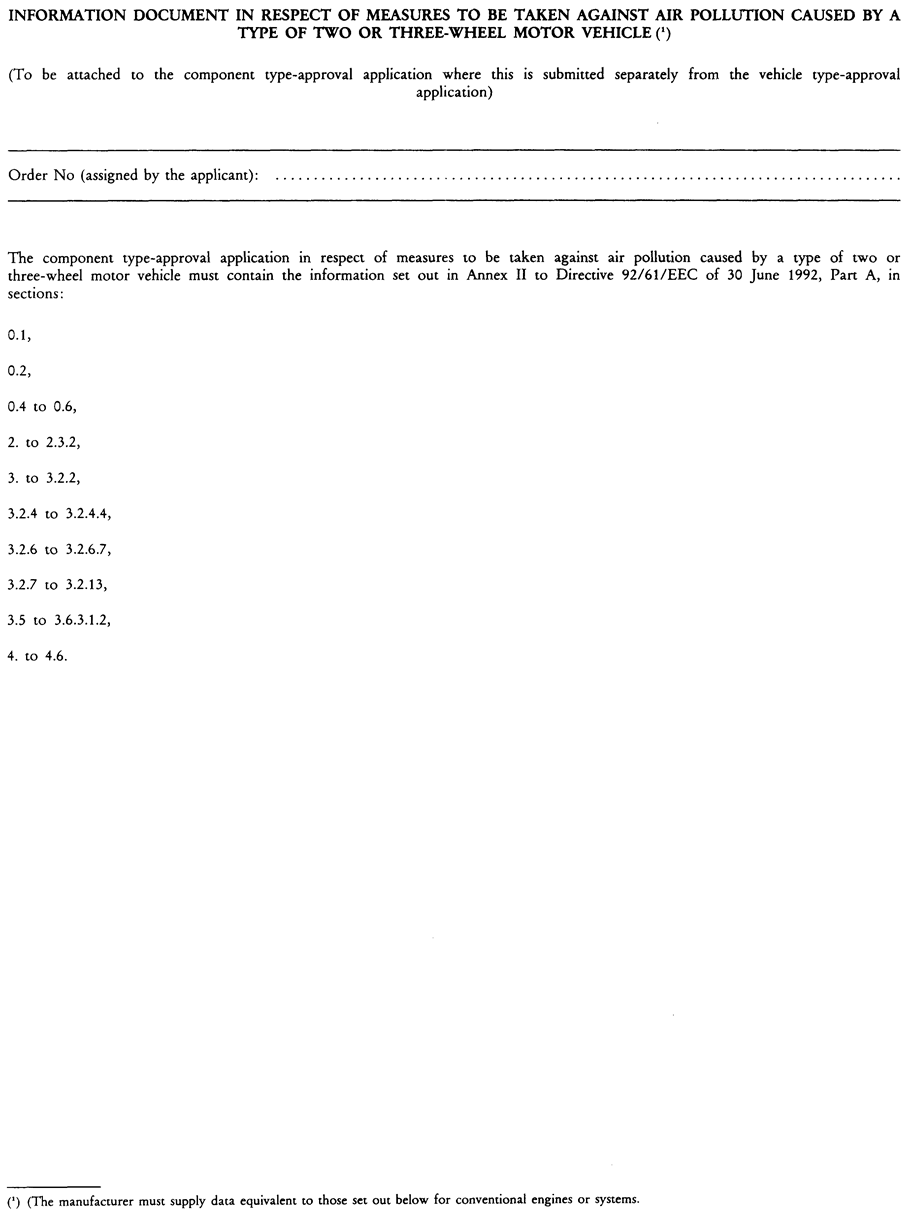

[F1ANNEX VII
TYPE-APPROVAL OF REPLACEMENT CATALYTIC CONVERTER AS SEPARATE TECHNICAL UNIT FOR TWO OR THREE-WHEEL MOTOR VEHICLES U.K.
This Annex applies to the type-approval, as separate technical units within the meaning of Article 2(5) of Directive 2002/24/EC, of catalytic converters to be fitted, on one or more types of two or three-wheel motor vehicles, as replacement parts.
1. DEFINITIONS U.K.
For the purposes of this Annex, the following definitions shall apply:
1.1. ‘ original equipment catalytic converter ’ means a catalytic converter or an assembly of catalytic converters covered by the type approval delivered for the vehicle; U.K.
1.2. ‘ replacement catalytic converter ’ means a catalytic converter or an assembly of catalytic converters intended to replace an original equipment catalytic converter on a vehicle type-approved in accordance with this Chapter which can be type-approved as a separate technical unit as defined in Article 2(5) of Directive 2002/24/EC; U.K.
1.3. ‘original replacement catalytic converter’ means a catalytic converter or an assembly of catalytic converters whose types are indicated in [F3section 4a of Annex VI] but are offered on the market as separate technical units by the holder of the vehicle type-approval; U.K.
1.4. ‘ type of catalytic converter ’ means catalytic converters which do not differ in such essential respects as the following: U.K.
1.4.1. number of coated substrates, structure and material; U.K.
1.4.2. type of catalytic activity (oxidising, three-way, etc.); U.K.
1.4.3. volume, ratio of frontal area and substrate length; U.K.
1.4.4. catalyst material content; U.K.
1.4.5. catalyst material ratio; U.K.
1.4.6. cell density; U.K.
1.4.7. dimensions and shape; U.K.
1.4.8. thermal protection; U.K.
1.5. ‘ vehicle type with regard to the emission of gaseous pollutants from the engine ’ means two or three-wheel motor vehicles which do not differ in such essential respects as the following: U.K.
1.5.1. the equivalent inertia determined in relation to the reference mass, as laid down in section 5.2 of Appendix 1 of Annex I or Annex II (depending upon the type of vehicle); U.K.
1.5.2. the characteristics of the engine and the two or three-wheel motor vehicle as defined in Annex V; U.K.
1.6. ‘gaseous pollutants’ means carbon monoxide, hydrocarbons and oxides of nitrogen expressed in terms of nitrogen dioxide (NO 2 ) equivalence. U.K.
2. APPLICATION FOR TYPE-APPROVAL U.K.
2.1. An application for type-approval of a type of replacement catalytic converter as a separate technical unit shall be submitted by the manufacturer of the system or by his authorised representative. U.K.
2.2. A model for the information document is given in Appendix 1. U.K.
2.3. For each type of catalytic converter for which approval is requested, the type-approval application must be accompanied by the following documents in triplicate, and by the following particulars: U.K.
2.3.1. description of the type(s) of vehicle for which the device is intended, in respect of the characteristics referred to in section 1.1 of Annex I or Annex II (depending upon the type of vehicle); U.K.
2.3.2. the numbers and/or symbols specific to the type of engine and vehicle; U.K.
2.3.3. description of the replacement catalytic converter stating the relative position of each of its components, together with the fitting instructions; U.K.
2.3.4. drawings of each component to facilitate location and identification, and statement of materials used. These drawings must also indicate the intended location of the mandatory type-approval number. U.K.
2.4. The following must be submitted to the technical service responsible for the type approval test: U.K.
2.4.1. Vehicle(s) of a type approved in accordance with this Chapter equipped with a new original equipment catalytic converter. This (these) vehicle(s) shall be selected by the applicant with the agreement of the technical service. It (they) shall comply with the requirements of Section 3 of Appendix 1 to Annex I, II or III (depending upon the type of vehicle). U.K.
The test vehicle(s) shall have no emission control system defects; any excessively worn out or malfunctioning emission-related original part shall be repaired or replaced. The test vehicle(s) shall be tuned properly and set to the manufacturer's specification prior to emission testing.
2.4.2. One sample of the type of the replacement catalytic converter. This sample shall be clearly and indelibly marked with the applicant's trade name or mark and its commercial designation. U.K.
3. GRANTING OF TYPE-APPROVAL U.K.
3.1. Upon completion of the tests laid down in this Annex, the competent authority shall issue a certificate based on the model set out in Appendix 2. U.K.
3.2. An approval number in accordance with Annex V to Directive 2002/24/EC shall be assigned to each type of replacement catalytic converter approved. The same Member State shall not assign the same number to another replacement catalytic converter type. The same type-approval number may cover the use of that replacement catalytic converter type on a number of different vehicle types. U.K.
4. MARKING REQUIREMENT U.K.
4.1. Every replacement catalytic converter conforming to the type approved under this Directive as a separate technical unit, but not the mounting parts and pipes, shall bear a type-approval mark composed in accordance with the requirements of Article 8 of Directive 2002/24/EC, supplemented by further information as referred to in section 4.2 of this Annex. The type-approval mark must be affixed in such a way as to be legible and indelible and also visible (where possible) in the position at which it is to be fitted. U.K.
The dimensions of ‘ a ’ must be ≥ 3 mm.
4.2. Further information contained in the type-approval mark U.K.
4.2.1. Every replacement catalytic converter, but not the mounting parts and pipes, must bear, in the type-approval mark, the number of the Chapter(s) under which the type approval has been granted. U.K.
4.2.1.1. Replacement catalytic converter which consists of a sole part integrating both the catalytic converter and the exhaust system (silencer) U.K.
The type-approval mark referred to in section 4.1 must be followed by two circles surrounding a number 5 and a number 9, respectively.
4.2.1.2. Replacement catalytic converter separated from the exhaust system (silencer) U.K.
The mark of the type-approval referred to in section 4.1 affixed to the replacement catalytic converter must be followed by a circle surrounding a number 5.
Examples of type-approval marks are given in Appendix 3.
5. REQUIREMENTS U.K.
5.1. General requirements U.K.
The design, construction and mounting of the replacement catalytic converter must be such that:
5.1.1. the vehicle complies with the requirements of the Annex under normal conditions of use, and in particular regardless of any vibrations to which it may be subjected; U.K.
5.1.2. the replacement catalytic converter displays reasonable resistance to the corrosion phenomena to which it is exposed, with due regard to the normal conditions of use of the vehicle; U.K.
5.1.3. the ground clearance available under the original equipment catalytic converter, and the angle at which the vehicle can lean over, are not reduced; U.K.
5.1.4. the surface does not reach unduly high temperatures; U.K.
5.1.5. the outline has no projections or sharp edges; U.K.
5.1.6. shock absorbers and suspension have adequate clearance; U.K.
5.1.7. adequate safety clearance is provided for pipes; U.K.
5.1.8. it is impact-resistant in a way that is compatible with clearly-defined maintenance and installation requirements; U.K.
5.1.9. if the original equipment catalytic converter includes thermal protection, the replacement catalytic converter shall include equivalent protection; U.K.
5.1.10. if (an) oxygen probe(s) and other sensors are originally installed on the exhaust line, the installation of the replacement catalytic converter shall be at the exact position of the original equipment catalytic converter, and the position on the exhaust line of the oxygen probe(s) and other sensors, shall not be modified. U.K.
5.2. Requirements regarding emissions U.K.
5.2.1. The vehicle referred to in section 2.4.1, equipped with a replacement catalytic converter of the type for which type-approval is requested, shall undergo the tests laid down in Appendices 1 and 2 to Annexes I, II or III (according to the type-approval of the vehicle) (9) . U.K.
5.2.1.1. Evaluation of the emission of pollutants of vehicles equipped with replacement catalytic converter U.K.
Requirements regarding emissions are deemed to be complied with if the test vehicle equipped with the replacement catalytic converter complies with the limit values according to Annex I, II or III (according to the type-approval of the vehicle) (10) .
Where type-approval is applied for different types of vehicles from the same manufacturer, and provided that these different types of vehicle are fitted with the same type of original equipment catalytic converter, the type I test may be limited to at least two vehicles selected after agreement with the technical service responsible for approval.
5.2.2. Requirements regarding permissible sound level U.K.
The vehicle referred to in section 2.4.1, equipped with a replacement catalytic converter of the type for which type-approval is requested, shall satisfy the requirements of section 3 to Annex II, III or IV to Chapter 9 (according to the type approval of the vehicle). The test result for the vehicle in motion and for the stationary test shall be mentioned in the test report.
5.3. Testing of vehicle performance U.K.
5.3.1. The replacement catalytic converter must be such as to ensure that the vehicle’s performance is comparable to that achieved with the original equipment catalytic converter. U.K.
5.3.2. The replacement catalytic converter must be compared with an original equipment catalytic converter, also in new condition, fitted in turn to the vehicle referred to in section 2.4.1. U.K.
5.3.3. This test is carried out by measuring the engine power curve. The net maximum power and the top speed measured with the replacement catalytic converter must not deviate from the net maximum power and top speed measured under the same conditions with the original equipment catalytic converter by more than ± 5 %. U.K.
6. CONFORMITY OF PRODUCTION U.K.
The provisions of Annex VI to Directive 2002/24/EC apply to the checking of conformity of production.
In order to test conformity as required above, a sample replacement catalytic converter must be taken from the production line of the type-approved, pursuant to this Annex.
Production will be regarded as being in conformity with the provisions of this Annex if the requirements of section 5.2 (Requirements regarding emissions) and section 5.3 (Testing of vehicle performance) are satisfied.
7. DOCUMENTATION U.K.
7.1. Each new replacement catalytic converter shall be accompanied by the following information: U.K.
7.1.1. the catalyst manufacturer's name or trade mark; U.K.
7.1.2. the vehicles (including year of manufacture) for which the replacement catalytic converter is approved; U.K.
7.1.3. installation instructions, where necessary. U.K.
7.2. This information shall be provided either on a leaflet accompanying the replacement catalytic converter, or on the packaging in which the replacement catalytic converter is sold, or by any other applicable means. U.K.
Appendix 1
Information document in respect of a replacement catalytic converter, as separate technical unit, for a type of two or three-wheel vehicle U.K.
Order No (assigned by applicant)
The type-approval application for replacement catalytic converter for a type of two or three-wheel vehicle must include the following details:
1.
Make of the device:...
2.
Type of the device:...
3.
Name and address of the manufacturer of the device:...
...
4.
If applicable, name and address of the authorised representative of the manufacturer of the device: ...
...
5.
Make(s) and type(s) of vehicle for which the device is designed (11) :
6.
Drawings of the replacement catalytic converter, identifying in particular all the characteristics referred to in section 1.4 of Annex VII to Chapter 5 annexed to Directive 97/24/EC: ...
...
7.
Description and drawings showing the position of the replacement catalytic converter relative to the engine exhaust manifold(s) and the oxygen sensor (if any): ...
8.
Any restrictions on use and fitting instructions: ...
9.
The details listed in Annex II to Directive 2002/24/CE, part 1 (A), sections:
0.1,
0.2,
0.5,
0.6,
2.1,
3,
3.0,
3.1,
3.1.1,
3.2.1.7,
3.2.12,
4 to 4.4.2,
4.5,
4.6,
5.2.
Appendix 2
Type-approval certificate in respect of a replacement catalytic converter for a type of two or three-wheel vehicle U.K.
Name of administration
Report No: ... by technical service: ... Date: ...
Type-approval No: ... No of extension: ...
1.
Make of the device: ...
2.
Type of the device: ...
3.
Name and address of the manufacturer of the device: ...
...
4.
If applicable, name and address of the authorised representative of the manufacturer of the device: ...
...
5.
Make(s) and type(s) and any variant(s) or version(s) of the vehicle(s) for which the device is designed: ...
...
6.
Date device submitted for testing: ...
7.
Type-approval granted/refused (12) :
8.
Place: ...
9.
Date: ...
10.
Signature: ...
Appendix 3
Examples of type-approval mark U.K.

The above represented type-approval mark was issued by Germany [e 1 ] under number 1230 for a replacement catalytic converter consisting of a sole part integrating both the catalytic converter and the exhaust system (silencer).

The above represented type-approval mark was issued by Germany [e 1 ] under number 1230 for the replacement catalytic converter not integrated in the exhaust system (catalytic converter and silencer not integrated in a sole element).

The above represented type-approval mark was issued by Germany [e 1 ] under number 1230 for the non-original silencer not integrating a catalytic converter (catalytic converter and silencer not integrated in a sole element or vehicle not equipped with a catalytic converter) (see Chapter 9).]
Editorial Information
X1 Substituted by Corrigendum to Directive 97/24/EC of the European Parliament and of the Council of 17 June 1997 on certain components and characteristics of two- or three-wheel motor vehicles (Official Journal of the European Communities L 226 of 18 August 1997).
Textual Amendments
F1 Inserted by Commission Directive 2005/30/EC of 22 April 2005 amending, for the purposes of their adaptation to technical progress, Directives 97/24/EC and 2002/24/EC of the European Parliament and of the Council, relating to the type-approval of two or three-wheel motor vehicles (Text with EEA relevance).
F2 Substituted by Commission Directive 2005/30/EC of 22 April 2005 amending, for the purposes of their adaptation to technical progress, Directives 97/24/EC and 2002/24/EC of the European Parliament and of the Council, relating to the type-approval of two or three-wheel motor vehicles (Text with EEA relevance).
F3 Substituted by Commission Directive 2006/120/EC of 27 November 2006 correcting and amending Directive 2005/30/EC amending, for the purposes of their adaptation to technical progress, Directives 97/24/EC and 2002/24/EC of the European Parliament and of the Council, relating to the type-approval of two or three-wheel motor vehicles (Text with EEA relevance).
F4 Substituted by Commission Directive 2006/27/EC of 3 March 2006 amending for the purposes of adapting to technical progress Council Directives 93/14/EEC on the braking of two- or three-wheel motor vehicles and 93/34/EEC on statutory markings for two- or three-wheel motor vehicles, Directives of the European Parliament and of the Council 95/1/EC on the maximum design speed, maximum torque and maximum net engine power of two- or three-wheel motor vehicles and 97/24/EC on certain components and characteristics of two- or three-wheel motor vehicles (Text with EEA relevance).
F5 Deleted by Commission Directive 2006/27/EC of 3 March 2006 amending for the purposes of adapting to technical progress Council Directives 93/14/EEC on the braking of two- or three-wheel motor vehicles and 93/34/EEC on statutory markings for two- or three-wheel motor vehicles, Directives of the European Parliament and of the Council 95/1/EC on the maximum design speed, maximum torque and maximum net engine power of two- or three-wheel motor vehicles and 97/24/EC on certain components and characteristics of two- or three-wheel motor vehicles (Text with EEA relevance).
F6 Substituted by Directive 2002/51/EC of the European Parliament and of the Council of 19 July 2002 on the reduction of the level of pollutant emissions from two- and three-wheel motor vehicles and amending Directive 97/24/EC (Text with EEA relevance).
F7 Inserted by Directive 2002/51/EC of the European Parliament and of the Council of 19 July 2002 on the reduction of the level of pollutant emissions from two- and three-wheel motor vehicles and amending Directive 97/24/EC (Text with EEA relevance).
F8 Substituted by Commission Directive 2003/77/EC of 11 August 2003 amending Directives 97/24/EC and 2002/24/EC of the European Parliament and of the Council relating to the type-approval of two- or three-wheel motor vehicles (Text with EEA relevance).
F9 Inserted by Commission Directive 2006/72/EC of 18 August 2006 amending for the purposes of adapting to technical progress Directive 97/24/EC of the European Parliament and of the Council on certain components and characteristics of two or three-wheel motor vehicles (Text with EEA relevance).
F10 Deleted by Commission Directive 2003/77/EC of 11 August 2003 amending Directives 97/24/EC and 2002/24/EC of the European Parliament and of the Council relating to the type-approval of two- or three-wheel motor vehicles (Text with EEA relevance).
(1)
where xi is any one of the individual results obtained with sample n and
(2)
These additional masses may where appropriate be replaced by an electronic device provided that the equivalence of the results is demonstrated.
(3)
[F6 [F9UN/ECE Global Technical Regulation No 2 ‘ Measurement procedure for two wheeled motorcycles equipped with a positive or compression ignition engine with regard to the emissions of gaseous pollutants, CO 2 emissions and fuel consumption ’ (ECE/TRANS/180/Add2 of 30 August 2005 ).] ]
(4)
where xi is any one of the individual results obtained with sample n and
(5)
These are additional masses which may where appropriate be replaced by an electronic device, provided that the equivalence of the results is demonstrated.
(6)
[F11These are additional masses which may, where appropriate, be replaced by an electronic device, provided that the equivalence of the results is demonstrated.
(7)
(8)
The test may be performed in an air-conditioned test cell where the atmospheric conditions can be controlled.
(9)
[F1As provided for in this Directive in the version applicable to the type-approval of that vehicle.
(10)
As provided for in this Directive in the version applicable to the type-approval of that vehicle.
(11)
Delete as appropriate.
(12)
Delete as appropriate.]
Textual Amendments
F1 Inserted by Commission Directive 2005/30/EC of 22 April 2005 amending, for the purposes of their adaptation to technical progress, Directives 97/24/EC and 2002/24/EC of the European Parliament and of the Council, relating to the type-approval of two or three-wheel motor vehicles (Text with EEA relevance).
F6 Substituted by Directive 2002/51/EC of the European Parliament and of the Council of 19 July 2002 on the reduction of the level of pollutant emissions from two- and three-wheel motor vehicles and amending Directive 97/24/EC (Text with EEA relevance).
Options/Help
Print Options
PrintThe Whole Directive
PrintThis Attachment only
Legislation is available in different versions:
Latest Available (revised):The latest available updated version of the legislation incorporating changes made by subsequent legislation and applied by our editorial team. Changes we have not yet applied to the text, can be found in the ‘Changes to Legislation’ area.
Original (As adopted by EU): The original version of the legislation as it stood when it was first adopted in the EU. No changes have been applied to the text.
Point in Time: This becomes available after navigating to view revised legislation as it stood at a certain point in time via Advanced Features > Show Timeline of Changes or via a point in time advanced search.
See additional information alongside the content
Geographical Extent: Indicates the geographical area that this provision applies to. For further information see ‘Frequently Asked Questions’.
Show Timeline of Changes: See how this legislation has or could change over time. Turning this feature on will show extra navigation options to go to these specific points in time. Return to the latest available version by using the controls above in the What Version box.
Opening Options
Different options to open legislation in order to view more content on screen at once
More Resources
Access essential accompanying documents and information for this legislation item from this tab. Dependent on the legislation item being viewed this may include:
- the original print PDF of the as adopted version that was used for the EU Official Journal
- lists of changes made by and/or affecting this legislation item
- all formats of all associated documents
- correction slips
- links to related legislation and further information resources
Timeline of Changes
This timeline shows the different versions taken from EUR-Lex before exit day and during the implementation period as well as any subsequent versions created after the implementation period as a result of changes made by UK legislation.
The dates for the EU versions are taken from the document dates on EUR-Lex and may not always coincide with when the changes came into force for the document.
For any versions created after the implementation period as a result of changes made by UK legislation the date will coincide with the earliest date on which the change (e.g an insertion, a repeal or a substitution) that was applied came into force. For further information see our guide to revised legislation on Understanding Legislation.
More Resources
Use this menu to access essential accompanying documents and information for this legislation item. Dependent on the legislation item being viewed this may include:
- the original print PDF of the as adopted version that was used for the print copy
- correction slips
Click 'View More' or select 'More Resources' tab for additional information including:
- lists of changes made by and/or affecting this legislation item
- confers power and blanket amendment details
- all formats of all associated documents
- links to related legislation and further information resources
 All content is available under the Open Government Licence v3.0 except where otherwise stated. This site additionally contains content derived from EUR-Lex, reused under the terms of the Commission Decision 2011/833/EU on the reuse of documents from the EU institutions. For more information see the EUR-Lex public statement on re-use.