Wall Type 1: Solid MasonryThe resistance to airborne sound depends mainly on the mass of the wall.
Points to watchFill masonry joints with mortar (to achieve the mass and to avoid air paths).
Limit the pathways around the wall (to reduce flanking transmission).
ConstructionsFive wall constructions which will give suitable resistance to direct transmission are specified.
Details of how junctions must be made to limit flanking transmission follow.
|  |
A. Brick, plastered both sides.
Mass including plaster 375 kg/m2.
13 mm plaster each side.
Lay bricks in a bond which includes headers.
|  |
B. Brick, plasterboard both sides.
Mass of masonry alone 395 kg/m2.
12.5 mm plasterboard each side, use any normal fixing method.
Lay bricks in a bond which includes headers.
|  |
C. Concrete block, plastered both sides.
Mass including plaster 415 kg/m2.
13 mm plaster each side.
Use blocks which extend to the full thickness of the wall.
|  |
D. Concrete block, plasterboard both sides.
Mass of masonry alone 415 kg/m2.
12.5 mm plasterboard each side, use any normal fixing method.
Use blocks which extend to the full thickness of the wall.
|  |
E. Concrete, in-situ or large panel.
Plaster optional.
Density 1500 kg/m3.
Mass (including plaster if used) 415 kg/m2.
Fill joints between panels with mortar.
|  |
| Junctions | |
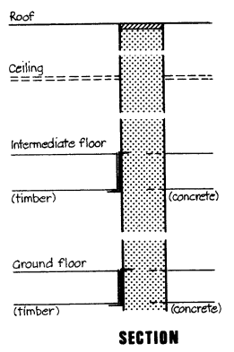
RoofFire-stop the joint between wall and roof.
Ceiling and roof spaceWhere there is a heavy ceiling (12.5 mm plasterboard or equivalent) with sealed joints, the mass of the wall above the ceiling may be reduced to 150 kg/m2. If lightweight blocks are used to reduce mass, seal one side of the wall with cement paint or plaster skim.
Intermediate and ground floorsWith a timber floor do not build joists into the wall, use joist hangers.
With a concrete floor either the wall or the floor may be carried through.
|  |
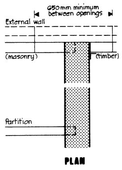
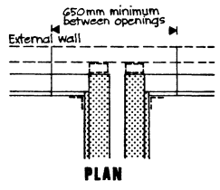
External wallThere must be 650 mm between openings which are on opposite sides of the separating wall.
The outer leaf of a cavity external wall may be of any construction.
An inner leaf or solid wall must not extend past the end of the separating wall.
A masonry inner leaf or solid wall must either be bonded to the separating wall or butted to it with ties no more than 300 mm apart vertically. A mass of 120 kg/m2 is required, except where the length of external wall is limited by large openings. (A short length of return wall will not vibrate and cause flanking transmission.) These openings must be at least 1 metre high, be on both sides of the wall at each storey, and be not more than 700 mm from the face of the wall.
The 650 mm minimum separation still applies, however.
A timber inner leaf or external wall must be butted tight against the separating wall with ties no more than 300 mm apart vertically. The joint between the lining to the external wall and the separating wall must be sealed with tape or caulking.
PartitionsThere are no restrictions on partition walls meeting a type 1 separating wall.
|  |
Wall Type 2: Cavity MasonryThe resistance to airborne sound depends on the mass of the leaves and on the degree of isolation achieved.
Points to watchFill masonry joints with mortar (to achieve the mass and to avoid air paths).
Maintain the cavity up to the underside of the roof.
Connect the leaves only where necessary for structural reasons. Use only butterfly pattern ties, spaced 900 mm apart horizontally and 450 mm apart vertically. (BS 5628 limits this tie type and spacing to cavities of 50 mm to 75 mm with a minimum masonry leaf thickness of 90 mm.)
If external walls are to be filled with an insulating material other than loose fibre the insulating material must be prevented from entering the cavity in the separating wall.
ConstructionsTwo wall constructions (A and B) which will give suitable resistance to direct transmission are specified.
Two other wall constructions (C and D) will be suitable provided a step and/or stagger is incorporated at the separating wall.
Details of how junctions must be made to limit flanking transmission follow.
| 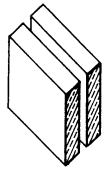 |
A. Two leaves of brick with 50 mm cavity, plastered on both room faces.
Mass including plaster 415 kg/m2.
13 mm plaster each face.
| 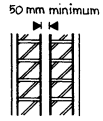 |
B. Two leaves of concrete block with 50 mm cavity, plastered on both room faces.
Mass including plaster 415 kg/m2.
Additional constructions permitted only where a step and/or stagger is used
| 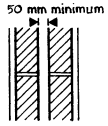 |
C. Two leaves of concrete block with 50 mm cavity, plasterboard on both room faces.
Mass of masonry alone 415 kg/m2.
12.5 mm plasterboard each face, use any normal fixing method.
| 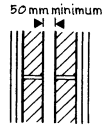 |
D. Two leaves of lightweight aggregate concrete block (maximum density 1500 kg/m3) with 75 mm cavity, plastered on both room faces.
Mass including plaster 250 kg/m2.
13 mm plaster each face.
Seal the face of the blockwork with cement paint or plaster through the full width and depth of any intermediate floor.
|  |
| Junctions | |
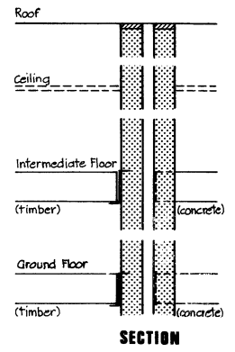
RoofFire-stop the joint between wall and roof.
Ceiling and roof spaceWhere there is a heavy ceiling (12.5 mm plasterboard or equivalent) with sealed joints, the mass of the wall above the ceiling may be reduced to 150 kg/m2. The cavity must still be maintained. If lightweight blocks are used to reduce mass one face of the wall must be sealed with cement paint or plaster skim.
Intermediate and ground floorsWith a timber floor use joist hangers for any joists supported on the wall.
With a concrete intermediate floor carry the floor through only to the cavity face of each leaf.
With a concrete ground floor either the wall or the floor may be carried through. A concrete slab on the ground may be continuous.
|  |
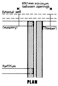
External wallThere must be 650 mm between openings which are on opposite sides of the separating wall.
The outer leaf of a cavity external wall may be of any construction.
An inner leaf or solid wall must not extend past the end of the separating wall.
A masonry inner leaf or solid wall must either be bonded to the separating wall or butted to it with ties no more than 300 mm apart vertically, and must have a mass of 120 kg/m2 unless wall B is used when there is no minimum required mass.
A timber inner leaf or external wall must be butted tight against the separating wall with ties no more than 300 mm apart vertically.
The joint between the lining to the external wall and the separating wall must be sealed with tape or caulking.
PartitionsThere are no restrictions on partition walls meeting a type 2 separating wall.
|  |
Wall Type 3: Solid Masonry between Freestanding PanelsThe resistance to airborne sound depends on the mass of the core and on the isolation and mass of the panels.
Points to watchFill masonry joints with mortar (to achieve the mass and to avoid air paths).
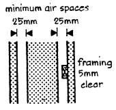
Support the panels only from floor and ceiling—do not fix or tie them to the masonry core (to maintain isolation).
Minimum air space between panels and core 25 mm.
Keep framing clear of core (at least 5 mm).
| 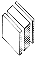 |
ConstructionsFour masonry cores and two panels are specified which in any combination of core plus panels will give suitable resistance to direct transmission. Details of how junctions must be made to limit flanking transmission follow.
|  |
Masonry coresA. Brick.
Mass 300 kg/m2.
|  |
B. Concrete block.
Mass 300 kg/m2.
|  |
C. Lightweight aggregate concrete block.
Mass 200 kg/m2.
Example: 140 mm core, 225 mm coursing; block density of 1405 kg/m3 gives the required mass.
Example: 215 mm core, 150 mm coursing; block density of 885 kg/m3 gives the required mass.
|  |
D. Autoclaved aerated concrete block.
Mass 160 kg/m2.
|  |
PanelsE. Two sheets of plasterboard joined by a cellular core.
Mass (including plaster finish if used) 18 kg/m2.
Fix to ceiling and floor only.
Tape joints between panels.
|  |
F. Two sheets of plasterboard.
Thickness of each sheet 12.5 mm if a supporting framework is used, or total thickness of 30 mm if no framework is used.
Stagger joints.
|  |
| Junctions | |
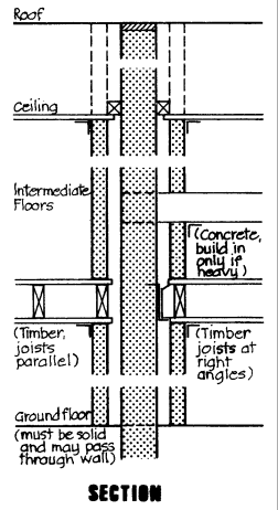
RoofFire-stop the joint between masonry core and roof.
Ceiling and roof spaceWhere there is a heavy ceiling (12.5 mm plasterboard or equivalent) with sealed joints, the freestanding panels may be omitted in the roof space and the mass of the core above the ceiling may be reduced to 150 kg/m2. If lightweight blocks are used to reduce mass, seal one side with cement paint or plaster skim. Seal the gap between the ceiling and the masonry core with a timber batten, and the gap between ceiling and freestanding panels with tape or caulking.
Intermediate and ground floorsWith a timber intermediate floor use joist hangers for any joists supported on the wall and seal the spaces between joists with full depth timber battens.
With a concrete intermediate floor the floor base may only be carried through where it has a mass of 365 kg/m2. Seal the gap between ceiling and panel with tape or caulking.
The ground floor must be a solid slab, laid on the ground (to prevent air paths).
|  |
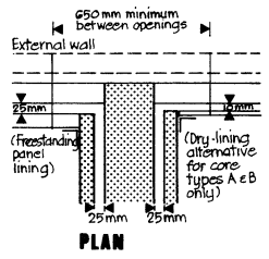
External wallThere must be 650 mm between openings which are on opposite sides of the separating wall.
Internal finish to the external wall must be freestanding panels of the type specified for the separating wall except, for cores A or B only, dry-lining with joints sealed with tape or caulking may also be used. A layer of insulation may be added to panels lining the external wall provided the 25 mm and 10 mm gaps shown on the diagram are maintained. If freestanding panels are used the external wall may be of any material. If dry-lining is used, the external wall leaf must be masonry with a mass of 120 kg/m2, butt jointed to the separating wall core with ties no more than 300 mm apart vertically.
|  |
PartitionsPartitions abutting a type 3 separating wall must not be of masonry construction.
Other loadbearing partitions should be fixed to the masonry core through a continuous pad of mineral fibre quilt.
Non-loadbearing partitions should be tight butted to the freestanding panels.
All joints between partitions and panels must be sealed with tape or caulking.
|  |
Wall Type 4: Timber Frames with Absorbent CurtainThe resistance to airborne sound depends on the isolation of the frames plus absorption in the air space between.
LimitationsThis type is limited to use between houses up to three storeys high excluding flats or maisonettes. (See Part D of the regulations, Structural Fire Precautions.) Use in flats and maisonettes is permitted by Class Relaxation Number 75, subject to certain conditions. The special walls specified in the Relaxation, for stairways, are suitable to resist sound transmission provided isolation of the leaves is maintained.
Points to watchOnly connect frames if necessary for structural reasons, and then use as few ties as possible—not more than 14–16 gauge (40 mm × 3 mm) metal straps fixed at or just below ceiling level, 1.2 m apart.
Services must not be contained in the wall. This is a structural fire precaution but also prevents the creation of air paths through the lining. Where fire-stops are needed in the cavity between frames they must either be flexible or fixed to only one frame.
ConstructionsTwo constructions which with appropriate cladding and absorbent will give suitable resistance to direct transmission are specified. Details of how junctions must be made to limit flanking transmission follow.
| 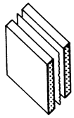 |
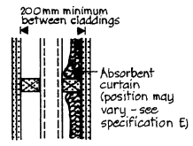
Basic constructionA. Timber frames, 200 mm between claddings, plus absorbent curtain in cavity.
Plywood sheathing may be used in the cavity as necessary for structural reasons.
|  |
B. Timber frames, masonry core, plus absorbent curtain in a cavity. Claddings 200 mm apart (ignore core). Framing must be clear of core (at least 5 mm).
| 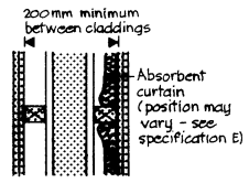 |
Masonry coreC. This does not normally improve sound resistance, but may be useful for support and in stepped or staggered situations. There are no restrictions on type of core but the core may be connected to more than one frame.
| |
CladdingD. On each side: two or more layers of plasterboard, combined thickness 30 mm, joints staggered to avoid air paths.
| |
Absorbent curtainE. Unfaced mineral fibre quilt (which may be wire reinforced), density 12–36 kg/m3, thickness 25 mm if suspended in the cavity between frames, 50 mm if fixed to one frame, or 25 mm per quilt if one fixed to each frame.
| |
| Junctions | |
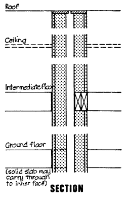
RoofFire-stop the joint between wall and roof.
Ceiling and roof spaceCarry the complete construction through to the underside of the roof. Provision of a ceiling of any type is optional.
Intermediate floor and ground floorBlock the air path to the wall cavity either by carrying the cladding through the floor or by using a solid timber edge to the floor. Where the joists are at right angles to the wall seal spaces between joists with full depth timber battens.
|  |
External wallThere must be 650 mm between openings which are on opposite sides of the separating wall.
There are no restrictions on the external cladding to a timber frame wall leaf but if an external leaf is used the cavity between the end of the wall frames and the outer leaf must be filled so as to seal air gaps.
Internal finishes to external wall. Use lining of 12.5 mm plasterboard or other equally heavy material. (Resilient layers for thermal insulation may be incorporated if desired.)
PartitionsThere are no restrictions on partitions meeting a Type 4 separating wall.
|  |
Floor Type 1: Concrete Base with Soft CoveringThe resistance to airborne sound depends on the mass of the concrete base and on eliminating air paths. The soft covering reduces impact sound at source.
LimitationsWhere resistance to airborne sound only is required the soft covering may be omitted.
No other part of the construction may be altered or omitted as this would reduce airborne sound resistance.
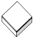
Points to watchFill all joints between parts of the floor (to avoid air paths).
Limit pathways around the floor (to reduce flanking transmission).
Workmanship and detailing must be good at the perimeters and wherever the floor is penetrated by a pipe or duct (to reduce flanking transmission and to avoid air paths).
|  |
ConstructionsFour floor bases which will give suitable resistance to direct transmission of airborne sound are specified, followed by the soft covering which must be added to any of the four to give suitable resistance to impact sound transmission.
Details of how junctions must be made to limit flanking transmission follow.
| |
Floor basesA. Solid concrete slab (in-situ).
Floor screed and/or ceiling finish optional.
Mass (including any bonded screed and/or ceiling finish) 365 kg/m2.
|  |
B. Solid concrete slab with permanent shuttering. Floor screed and/or ceiling finish optional.
Mass (including shuttering only if it is solid concrete or metal, and including any bonded screed and/or ceiling finish) 365 kg/m2.
|  |
C. Concrete beams with infilling blocks.
Floor screed must be used.
Ceiling finish optional.
Mass of beams, blocks and screed (including any bonded ceiling finish) 365 kg/m2.
|  |
D. Concrete planks (solid or hollow).
Floor screed must be used.
Ceiling finish optional.
Mass of planks plus screed (including any bonded ceiling finish) 365 kg/m2.
|  |
Soft coveringE. Any resilient material, or material with a resilient base, with an overall uncompressed thickness of 4.5 mm. Suitable resilience will also be provided by a floor covering with a weighted impact sound improvement index (Δ Lw) of 17 as calculated in Annex A to BS 5821: Part 2: 1984. The soft covering must be bonded to the floor base.
| |
| Junctions | |
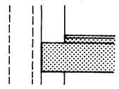
External wall or cavity separating wallThe mass of any solid wall or inner leaf of a cavity wall adjoining the floor must be 120 kg/m2 (including any plaster) except, where the area of openings in the external wall exceeds 20% of its area, there is no minimum mass.
The floor base (excluding any screed, even in C or D) must pass through the wall whether spanning parallel to or at right angles to the wall. Do not bridge a cavity.
|  |
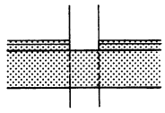
Internal wall or solid separating wallIf the wall mass is less than 355 kg/m2 (including any plaster) the floor base (excluding any screed) must pass through.
If the wall mass is more than 355 kg/m2 (including any plaster) either the wall or the floor base (excluding any screed) may pass through. Where the wall does pass through tie the floor base to the wall and grout the joint.
|  |
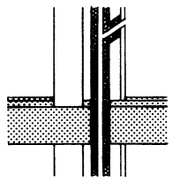
Floor penetrationsDucts or pipes penetrating the floor must be in a duct enclosure, both above and below the floor.
Either line the enclosure, or wrap the duct or pipe within the enclosure, with 25 mm unfaced mineral fibre.
The material of the enclosure must have a mass of 15 kg/m2 (and be non-combustible in certain cases—see regulation D12).
Flexible fire-stopping must be used where the pipe or duct passes through the floor.
Where permitted by regulation D11, a flue-pipe may penetrate the floor. Unless the flue-pipe dis>dh
charges into a flue within a chimney carried by the floor, a non-combustible enclosing duct with mineral fibre absorbent must be provided.
|  |
Floor Type 2: Concrete Base with Floating LayerThe resistance to airborne sound depends mainly on the mass of the concrete base and partly on the mass of the floating layer.
Resistance to impact sound depends on a resilient layer isolating the floating layer from the base and from the surrounding construction.
LimitationsWhere resistance to airborne sound only is required the full construction must still be used.
Resilient layers need not be used under kitchen or sanitary fittings, or in cupboards or wardrobes.
Points to watchFill all joints between parts of the floor base (to avoid air paths).
Limit the pathways around the floor (to reduce flanking transmission).
Workmanship and detailing must be good at the perimeters and wherever the floor is penetrated (to reduce flanking transmission and to avoid air paths).
Take care not to create a bridge between the floating layer and the base, surrounding walls, or adjacent screeds.
With bases C and D a screed is recommended where differences in camber might cause bridging of the resilient layer and where the top chord of a trough section is less than 50 mm thick (to prevent areas of reduced resistance).
| 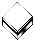 |
ConstructionsFour floor bases, two floating layers and one resilient layer are specified and will in any combination of base, resilient layer and floating layer give suitable resistance to direct transmission. Two additional resilient layers which may be used only under screeds are specified also (H and I). Details of how junctions must be made to limit flanking transmission follow.
| |
Floor basesA. Solid concrete slab (in-situ).
Floor screed and/or ceiling finish optional.
Mass (including any bonded screed and/or ceiling finish) 300 kg/m2.
|  |
B. Solid concrete slab with permanent shuttering.
Floor screed and/or ceiling finish optional.
Mass (including shuttering only if it is solid concrete or metal, and including any bonded screed and/or ceiling finish) 300 kg/m2.
|  |
C. Concrete beams with infilling blocks.
Floor screed and/or ceiling finish optional.
Mass of beams and blocks (including any bonded screed or ceiling finish) 300 kg/m2.
|  |
D. Concrete planks (solid or hollow).
Floor screed and/or ceiling finish optional.
Mass of planks (including any bonded screed or ceiling finish) 300 kg/m2.
|  |
Floating layersE. Timber raft.
Timber boarding or wood based board, 18 mm thick and with tongued and grooved edges, fixed to 45×45 mm battens. The raft must be laid loose on the resilient layer.
|  |
F. Screed.
65mm cement/sand screed or 40 mm anhydrite screed, with mesh reinforcement.
|  |
Resilient layerG. 25 mm mineral fibre, density 36 kg/m3, covering the whole area of the floor. A 13 mm thickness may be used under a timber raft if the battens used have an integral closed cell resilient foam strip.
Lay the fibre rolls tightly butted, and turned up at the edges of floating layer.
Under a timber raft, fibre may be paper faced on the underside.
Under a screed, fibre must be paper faced on upper side (to prevent screed entering the layer).
| |
Additional resilient layers for use only under screedsH. 13 mm pre-compressed expanded polystyrene board (impact sound duty grade). Lay boards tightly butted, use on edge as a resilient strip at edges of floating screed.
| |
I. 5 mm extruded (closed cell) polyethylene foam, density 30–45 kg/m3. Lay with joints lapped. Turn up at edges of floating screed.
| |
| Junctions | |
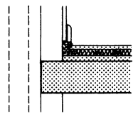
External wall or cavity separating wallThe mass of any solid wall or inner leaf of a cavity wall adjoining the floor must be 120 kg/m2 (including any plaster) except, where the area of openings in the external wall exceeds 20% of its area, there is no minimum mass.
The floor base (excluding any screed) must pass through the wall whether spanning parallel to or at right angles to the wall. Do not bridge a cavity.
Carry the resilient layer up at all edges to isolate the floating layer.
Leave a 3 mm gap between skirting and floating layer or turn resilient layer under skirting. A seal is not necessary but if used must be flexible.
|  |
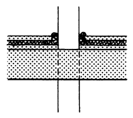
Internal wall or solid separating wallIf the wall mass is less than 355 kg/m2 (including any plaster) the floor base (excluding any screed) must pass through.
If the wall mass is more than 355 kg/m2 (including any plaster) either the wall or the floor base (excluding any screed) may pass through.Where the wall does pass through, tie the floor base to the wall and grout the joint.
|  |
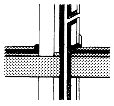
Floor penetrationsDucts or pipes penetrating the floor must be in a duct enclosure, both above and below the floor.
Either line the enclosure, or wrap the duct or pipe within the enclosure, with 25 mm unfaced mineral fibre.
The material of the enclosure must have a mass of 15 kg/m2 (and be non-combustible in certain cases—see regulation D12).
Leave a 3 mm gap between enclosure and floating layer, and seal with acrylic caulk or neoprene.
Flexible fire-stopping must be used where the pipe or duct passes through the floor.
Where permitted by regulation D11, a flue-pipe may penetrate the floor. Unless the flue-pipe discharges into a flue within a chimney carried by the floor, a non-combustible enclosing duct with mineral fibre absorbent must be provided.
|  |
Floor Type 3: Timber Base with Floating LayerThe resistance to airborne sound depends partly on the structural floor plus absorbent blanket or deafening (pugging), and partly on the floating layer. Resistance to impact sound depends on a resilient layer isolating the floating layer from the base and the surrounding construction.
LimitationsWhere resistance to airborne sound only is required the full construction must still be used.
This type of floor is limited to use in a building not more than four storeys in height where the fire resistance satisfies Part D of the regulations. This type can also be used as a specified construction for converted properties. Use is only permitted with appropriate supporting walls (see “Junctions” below).
Points to watchLimit the pathways around the floor (to reduce flanking transmission).
Workmanship and detailing must be good at the perimeter and wherever the floor is penetrated (to reduce flanking transmission and to avoid air paths).
The density of the resilient layer is important.
Take care not to bridge between the floating layer and the base or surrounding walls (eg with services or fixings which penetrate the resilient layer). Allow for movement of materials eg expansion of chipboard after laying (to maintain isolation).
ConstructionsThree complete constructions which will give suitable resistance to direct sound transmission are specified. Note that there are some alternatives within each construction. Details of how junctions must be made to limit flanking transmission follow.
|  |
FloorsA. Platform floor with absorbent blanket.
Floating layer of either timber boarding or wood-based board, 18 mm thick and with tongued and grooved edges, spot bonded to substrate of 19 mm plasterboard, or two layers of cement bonded particle board, each 6 mm thick, joints staggered, glued and screwed together.
Resilient layer of 25 mm mineral fibre, density 60–80 kg/m3.
Floor base of 12 mm timber boarding or wood-based board nailed to timber joists (size to suit structure).
Ceiling of two layers of plasterboard, with joints staggered, total thickness 30 mm, with an absorbent blanket of 100 mm unfaced mineral fibre, density 12–36 kg/m2, laid on the ceiling.
|  |
B. Heavy ribbed floor with absorbent blanket or deafening (pugging)*.
Floating layer of timber boarding or wood-based board, 18 mm thick and with tongued and grooved edges (joints to be glued), on substrate of 19 mm plasterboard nailed to 45 mm×45 mm timber battens placed on joists.
Resilient strips of 25 mm mineral fibre, density 70–140 kg/m3, laid on joists.
Floor base of 45 mm timber joists.
Ceiling of either two layers of plasterboard with joints staggered, total thickness 30 mm, with an absorbent blanket of 100 mm unfaced mineral fibre, density 12–36 kg/m3, laid on the ceiling; or 6 mm plywood fixed under joists plus two layers of plasterboard with joints staggered, total thickness 30 mm, with deafening (pugging) of mass 50 kg/m2 on a polyethylene liner.
|  |
C. Ribbed floor with heavy deafening (pugging)*.
Floating layer of timber boarding or wood-based board, 18 mm thick and with tongued and grooved edges (joints to be glued), nailed to 45 mm×45 mm timber battens placed either on or between joists.
Resilient strips of 25 mm mineral fibre, density 70–140 kg/m3, laid on joists.
Floor base of 45 mm timber joists.
Ceiling of either 19 mm dense plaster on expanded metal lath or 6 mm plywood fixed under the joists plus two layers of plasterboard with joints staggered, total thickness 25 mm.
Both types of ceiling to have deafening (pugging) of mass 80 kg/m2 laid on a polyethylene liner.
*Deafening (pugging) may be of the following types:–
Traditional ash (75 mm);
2–10 mm limestone chips (60 mm);
2–10 mm whin aggregate (60 mm);
Dry sand (50 mm).
Figures in brackets show approx thickness required to achieve 80 kg/m2.
Do not use sand in kitchens, bathrooms, water closets or utility rooms.
|  |
| Junctions | |
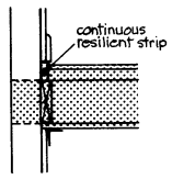
Timber frame wallSeal the gap between wall and floating layer with a resilient strip glued to the wall.
Leave a 3 mm gap between skirting and floating layer. A seal is not necessary but if used must be flexible.
Block air paths between the floor base and the wall, including the space between joists when joists are at right angles to the wall.
Seal the junction of ceiling and wall lining with tape or caulking.
|  |
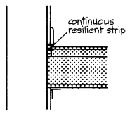
Heavy masonry leafMass of leaf (including any plaster) 355 kg/m2, both above and below floor.
Seal the gap between wall and floating layer with a resilient strip glued to the wall.
Leave a 3 mm gap between skirting and floating layer. A seal is not necessary but if used must be flexible.
Use any normal method of connecting floor base to wall.
Seal the junction of ceiling and wall lining with tape or caulking.
|  |
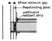
Light masonry leafIf the mass (including any plaster) is less than 355 kg/m2 a freestanding panel as specified in Wall Type 3 must be used.
Seal the gap between wall and floating layer with a resilient strip glued to the freestanding panel.
Leave a 3 mm gap between skirting and floating layer. A seal is not necessary but if used must be flexible.
Use any method of connecting floor base to wall, but block air paths between floor and wall cavities.
Take ceiling through to masonry, seal junction with freestanding panel with tape or caulking.
|  |
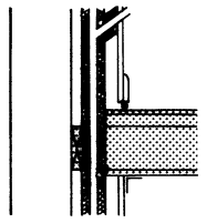
Floor penetrationsDucts or pipes penetrating the floor must be in a duct enclosure both above and below the floor.
Either line the enclosure, or wrap the duct or pipe within the enclosure, with 25 mm unfaced mineral fibre.
The material of the enclosure must have a mass of 15 kg/m2 (and be non-combustible in certain cases—see regulation D12).
Leave a 3 mm gap between enclosure and floating layer, seal with acrylic caulk or neoprene. (Enclosure may go down to the floor base if specification A is used, but maintain isolation of enclosure from floating layer.)
Flexible fire-stopping must be used where the pipe or duct passes through the floor.
Where permitted by regulation D11, a flue-pipe may penetrate the floor. The flue-pipe must be in a non-combustible enclosing duct with mineral fibre absorbent.
Seal the junction of ceiling and enclosure with tape or caulking.
|  |
Floor Type 4: Timber Base with Independent CeilingThe resistance to airborne and impact sound depends mainly on the mass and isolation of the independent ceiling, and partly on the mass of the floor base.
LimitationsWhere resistance to airborne sound only is required the full construction must still be used.
This type is limited to use in a building not more than four storeys in height where the fire resistance satisfies Part D of the regulations.
It must be used only with heavy masonry walls. It is mainly for use as a specified construction for converted properties with suitable existing floors and walls.
Points to watchLimit the pathways around the floor, especially at the edges of the independent ceiling (to reduce flanking transmission and to avoid air paths).
Workmanship and detailing must be good wherever the floor is penetrated.
Take care not to create bridges between the floor base and the independent ceiling.
ConstructionThe construction specified below will give suitable resistance to direct sound transmission.
Details of how junctions must be made to limit flanking transmission follow.
| 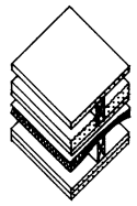 |
FloorTimber boarding or wood-based board, 18 mm thick with tongued and grooved edges (or overlaid with 3.2 mm hardboard to seal gaps).
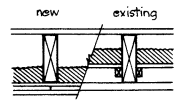
45 mm joists plus deafening (pugging) of mass 80 kg/m2 and a ceiling of either 19 mm dense plaster on lath or two layers of plasterboard with joints staggered, total thickness 30 mm. In existing floors deafening may be on boards between joists, in new floors use 6 mm plywood fixed to underside of joists. (A polyethylene liner may be used if desired.)
|  |
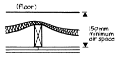
Independent ceilingAbsorbent blanket of 25 mm unfaced mineral fibre, density 12–36 kg/m2, draped over 45 mm joists supported independently of the floor. Ceiling of two layers of plasterboard with joints staggered, total thickness 30 mm. Keep ceiling 150 mm away from the floor base underside.
|  |
| Junctions | |
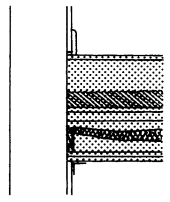
External wall or separating wallMass of leaf must be 355 kg/m2 (including any plaster), both above and below the floor, on at least 3 sides. Leaf on fourth side must be at least 180 kg/m2.
Use bearers on walls (fixed through mineral fibre strip) to support the edges of the ceiling and to block air paths.
Seal the junction of ceiling and wall with tape or caulking.
Internal wallIf masonry, mass must be 180 kg/m2.
No restriction if stud partition.
Support and edge ceiling as for external walls.
|  |
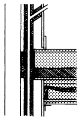
Floor penetrationsDucts or pipes penetrating the floor must be in a duct enclosure both above and below the floor.
Either line the enclosure, or wrap the duct or pipe within the enclosure, with 25 mm unfaced mineral fibre.
The material of the enclosure must have a mass of 15 kg/m2 (and be non-combustible in certain cases—see regulation D12).
Flexible fire-stopping must be used where the pipe or duct passes through the floor.
Where permitted by regulation D11, a flue-pipe may penetrate the floor. The flue-pipe must be in a non-combustible enclosing duct with mineral fibre absorbent.
Seal the junction of ceiling and enclosure with tape or caulking.
|  |


