- Latest available (Revised)
- Point in Time (19/12/2005)
- Original (As adopted by EU)
Directive 2005/55/EC of the European Parliament and of the Council (repealed)Show full title
Directive 2005/55/EC of the European Parliament and of the Council of 28 September 2005 on the approximation of the laws of the Member States relating to the measures to be taken against the emission of gaseous and particulate pollutants from compression-ignition engines for use in vehicles, and the emission of gaseous pollutants from positive-ignition engines fuelled with natural gas or liquefied petroleum gas for use in vehicles (Text with EEA relevance) (repealed)
You are here:
- Directives originating from the EU
- 2005 No. 55
- Whole Directive
- Previous
- Next

What Version
Advanced Features
- Show Geographical Extent(e.g. England, Wales, Scotland and Northern Ireland)
- Show Timeline of Changes
More Resources
Revised version PDFs
- Revised 31/12/20130.45 MB
- Revised 08/08/20082.04 MB
- Revised 10/06/20064.30 MB
- Revised 19/12/20052.67 MB
Legislation originating from the EU
When the UK left the EU, legislation.gov.uk published EU legislation that had been published by the EU up to IP completion day (31 December 2020 11.00 p.m.). On legislation.gov.uk, these items of legislation are kept up-to-date with any amendments made by the UK since then.


This item of legislation originated from the EU
Legislation.gov.uk publishes the UK version. EUR-Lex publishes the EU version. The EU Exit Web Archive holds a snapshot of EUR-Lex’s version from IP completion day (31 December 2020 11.00 p.m.).
Changes over time for: Directive 2005/55/EC of the European Parliament and of the Council (repealed)
Version Superseded: 10/06/2006
Status:
EU Directives are published on this site to aid cross referencing from UK legislation. Since IP completion day (31 December 2020 11.00 p.m.) no amendments have been applied to this version.
Directive 2005/55/EC of the European Parliament and of the Council
of 28 September 2005
on the approximation of the laws of the Member States relating to the measures to be taken against the emission of gaseous and particulate pollutants from compression-ignition engines for use in vehicles, and the emission of gaseous pollutants from positive-ignition engines fuelled with natural gas or liquefied petroleum gas for use in vehicles
(Text with EEA relevance) (repealed)
THE EUROPEAN PARLIAMENT AND THE COUNCIL OF THE EUROPEAN UNION,
Having regard to the Treaty establishing the European Community, and in particular Article 95 thereof,
Having regard to the proposal from the Commission,
Having regard to the opinion of the European Economic and Social Committee(1),
Acting in accordance with the procedure laid down in Article 251 of the Treaty(2),
Whereas:
(1) Council Directive 88/77/EEC of 3 December 1987 on the approximation of the laws of the Member States relating to the measures to be taken against the emission of gaseous and particulate pollutants from compression ignition engines for use in vehicles, and the emission of gaseous pollutants from positive ignition engines fuelled with natural gas or liquefied petroleum gas for use in vehicles(3) is one of the separate Directives under the type-approval procedure laid down by Council Directive 70/156/EEC of 6 February 1970 on the approximation of the laws of the Member States relating to the type-approval of motor vehicles and their trailers(4). Directive 88/77/EEC has been substantially amended several times to introduce successively more stringent pollutant emission limits. Since further amendments are to be made, it should be recast in the interests of clarity.
(2) Council Directive 91/542/EEC(5) amending Directive 88/77/EEC, Directive 1999/96/EC of the European Parliament and of the Council of 13 December 1999 on the approximation of the laws of the Member States relating to measures to be taken against the emission of gaseous and particulate pollutants from compression ignition engines for use in vehicles, and the emission of gaseous pollutants from positive ignition engines fuelled with natural gas or liquefied petroleum gas for use in vehicles and amending Council Directive 88/77/EEC(6), and Commission Directive 2001/27/EC(7) adapting to technical progress Council Directive 88/77/EEC have introduced provisions which, while being autonomous, are closely linked to the scheme established under Directive 88/77/EEC. Those autonomous provisions should be fully integrated into the recast of Directive 88/77/EEC in the interests of clarity and legal certainty.
(3) It is necessary that all the Member States adopt the same requirements, in order, in particular, to permit the implementation, for each vehicle type, of the EC type-approval system which is the subject of Directive 70/156/EEC.
(4) The Commission’s programme on air quality, road transport emissions, fuels and emission abatement technologies, hereinafter ‘the first Auto-Oil programme’, showed that further reductions in pollutant emissions from heavy-duty vehicles were necessary with a view to achieving future air quality standards.
(5) Reductions in emission limits applicable from the year 2000, corresponding to abatements of 30 % in emissions of carbon monoxide, total hydrocarbons, oxides of nitrogen and particulate matter were identified by the first Auto-Oil programme as key measures for the achievement of medium-term air quality. A reduction of 30 % in exhaust smoke opacity should additionally contribute to the reduction of particulate matter. Additional reductions in emission limits applicable from the year 2005, corresponding to additional abatements of 30 % in carbon monoxide, total hydrocarbons and oxides of nitrogen and 80 % in particulate matter should greatly contribute to air quality improvement in the medium to longer term. The additional limit for oxides of nitrogen applicable in the year 2008 should result in a further 43 % reduction in the emission limit for this pollutant.
(6) Type-approval tests for gaseous and particulate pollutants and smoke opacity are applicable to allow for a more representative evaluation of the emissions performance of engines under test conditions that more closely resemble those encountered by vehicles in-service. Since 2000 conventional compression-ignition engines and those compression-ignition engines fitted with certain types of emission control equipment have been tested over a steady-state test cycle and using a new load response test for smoke opacity. Compression-ignition engines fitted with advanced emission control systems have, in addition, been tested over a new transient test cycle. From 2005, all compression-ignition engines should be tested on all those test cycles. Gas fuelled engines are only tested on the new transient test cycle.
(7) Under all randomly selected load conditions within a defined operating range, the limit values may not be exceeded by more than an appropriate percentage.
(8) In laying down new standards and test procedures, it is necessary to take account of the impact on air quality of future traffic growth in the Community. The work undertaken by the Commission in this sphere has shown that the motor industry in the Community has made great strides in the perfection of the technology allowing a considerable reduction in emissions of gaseous and particulate pollutants. However, it is still necessary to press for further improvements in emission limits and other technical requirements in the interests of environmental protection and public health. In particular, the results of ongoing research into the characteristics of ultra-fine particulates should be taken into account in any future measures.
(9) It is necessary that further improvements be made to the quality of motor fuels to enable the efficient and durable performance of emission control systems in service.
(10) New provisions for on-board diagnostics (OBD) should be introduced from 2005 with a view to facilitating the immediate detection of the deterioration or failure of engine emission control equipment. This should enhance diagnostic and repair capability, significantly improving the sustainable emission performance of in-service heavy-duty vehicles. Since, on the worldwide stage, OBD for heavy-duty diesel engines is in its infancy, it should be introduced in the Community in two stages to allow for system development so that the OBD system does not give false indications. In order to assist the Member States in ensuring that the owners and operators of heavy-duty vehicles meet their obligation to repair faults indicated by the OBD system, the distance covered or the time that has elapsed after a fault has been indicated to the driver should be recorded.
(11) Compression-ignition engines are inherently durable and have demonstrated that, with proper and effective maintenance, they can retain a high level of emissions performance over the significantly high distances travelled by heavy-duty vehicles in the course of commercial operations. However, future emission standards will push the introduction of emission control systems downstream of the engine, such as deNOx systems, diesel particulate filters and systems that are a combination of both and, perhaps, other systems yet to be defined. It is therefore necessary to establish a useful life requirement on which to base procedures for ensuring the compliance of an engine’s emission control system throughout that reference period. In establishing such a requirement, due account should be taken of the considerable distances covered by heavy-duty vehicles, of the need to incorporate appropriate and timely maintenance and of the possibility of type-approving category N1 vehicles in accordance with either this Directive or Council Directive 70/220/EEC of 20 March 1970 on the approximation of the laws of the Member States on measures to be taken against air pollution by emissions from motor vehicles(8).
(12) Member States should be allowed, by means of tax incentives, to expedite the placing on the market of vehicles that satisfy the requirements adopted at Community level, provided that such incentives comply with the provisions of the Treaty and satisfy certain conditions intended to prevent distortion of the internal market. This Directive does not affect the right of the Member States to include emissions of pollutants and other substances in the basis for calculating road traffic taxes on motor vehicles.
(13) Since some of those tax incentives are State aids under Article 87(1) of the Treaty, they would have to be notified to the Commission under Article 88(3) of the Treaty for evaluation in accordance with the relevant criteria of compatibility. The notification of such measures in accordance with this Directive should be without prejudice to the obligation to notify under Article 88(3) of the Treaty.
(14) With the aim of simplifying and accelerating the procedure, the Commission should be entrusted with the task of adopting measures implementing the fundamental provisions laid down in this Directive as well as the measures for adapting the annexes of this Directive to scientific and technical progress.
(15) The measures necessary for the implementation of this Directive and its adaptation to scientific and technical progress should be adopted in accordance with Council Decision 1999/468/EC of 28 June 1999 laying down the procedures for the exercise of implementing powers conferred on the Commission(9).
(16) The Commission should keep under review the need to introduce emission limits for pollutants which are as yet unregulated and which arise as a consequence of the wider use of new alternative fuels and new exhaust emission control systems.
(17) The Commission should submit proposals it may deem appropriate for a further stage for limit values for NOx and particulate emissions as soon as possible.
(18) Since the objective of this Directive, namely the realisation of the internal market through the introduction of common technical requirements concerning gaseous and particulate emissions for all types of vehicles, cannot be sufficiently achieved by the Member States and can therefore, by reason of the scale of the action, be better achieved at Community level, the Community may adopt measures, in accordance with the principle of subsidiarity, as set out in Article 5 of the Treaty. In accordance with the principle of proportionality, as set out in that Article, this Directive does not go beyond what is necessary in order to achieve this objective.
(19) The obligation to transpose this Directive into national law should be confined to those provisions which represent a substantive change as compared with the earlier Directives. The obligation to transpose the provisions which are unchanged arises under the earlier Directives.
(20) This Directive should be without prejudice to the obligations of the Member States relating to the time limits for transposition into national law and application of the Directives set out in Annex IX, Part B.
HAVE ADOPTED THIS DIRECTIVE:
Article 1U.K.Definitions
For the purposes of this Directive the following definitions shall apply:
(a)
‘vehicle’ means any vehicle as defined in Article 2 of Directive 70/156/EEC and propelled by a compression-ignition or gas engine, with the exception of vehicles of category M1 with a technically permissible maximum laden mass less than or equal to 3,5 tonnes;
(b)
‘compression-ignition or gas engine’ means the motive propulsion source of a vehicle for which type-approval as a separate technical unit, as defined in Article 2 of Directive 70/156/EEC, may be granted;
(c)
‘enhanced environment-friendly vehicle (EEV)’ means a vehicle propelled by an engine which complies with the permissive emission limit values set out in row C of the tables in Section 6.2.1 of Annex I.
Article 2U.K.Obligations of the Member States
1.For types of compression-ignition or gas engines and types of vehicle propelled by compression-ignition or gas engines, where the requirements set out in Annexes I to VIII are not met and in particular where the emissions of gaseous and particulate pollutants and opacity of smoke from the engine do not comply with the limit values set out in row A of the tables in Section 6.2.1 of Annex I, Member States:
(a)shall refuse to grant EC type-approval pursuant to Article 4(1) of Directive 70/156/EEC; and
(b)shall refuse national type-approval.
2.Except in the case of vehicles and engines intended for export to third countries or replacement engines for in-service vehicles, Member States shall, where the requirements set out in Annexes I to VIII are not met and in particular where the emissions of gaseous and particulate pollutants and opacity of smoke from the engine do not comply with the limit values set out in row A of the tables in Section 6.2.1 of Annex I:
(a)consider certificates of conformity which accompany new vehicles or new engines pursuant to Directive 70/156/EEC as no longer valid for the purposes of Article 7(1) of that Directive; and
(b)prohibit the registration, sale, entry into service or use of new vehicles propelled by a compression-ignition or gas engine and the sale or use of new compression-ignition or gas engines.
3.Without prejudice to paragraphs 1 and 2, with effect from 1 October 2003 and except in the case of vehicles and engines intended for export to third countries or replacement engines for in-service vehicles, Member States shall, for types of gas engines and types of vehicles propelled by a gas engine which do not comply with the requirements set out in Annexes I to VIII:
(a)consider certificates of conformity which accompany new vehicles or new engines pursuant to Directive 70/156/EEC as no longer valid for the purposes of Article 7(1) of that Directive; and
(b)prohibit the registration, sale, entry into service or use of new vehicles and the sale or use of new engines.
4.If the requirements set out in Annexes I to VIII and in Articles 3 and 4 are satisfied, in particular where the emissions of gaseous and particulate pollutants and opacity of smoke from the engine comply with the limit values set out in row B1 or row B2 or with the permissive limit values set out in row C of the tables in Section 6.2.1 of Annex I, no Member State may, on grounds relating to the gaseous and particulate pollutants and opacity of smoke emissions from an engine:
(a)refuse to grant EC type-approval pursuant to Article 4(1) of Directive 70/156/EEC or to grant national type-approval for a type of vehicle propelled by a compression-ignition or gas engine;
(b)prohibit the registration, sale, entry into service or use of new vehicles propelled by a compression-ignition or gas engine;
(c)refuse to grant EC type-approval for a type of compression-ignition or gas engine;
(d)prohibit the sale or use of new compression-ignition or gas engines.
5.With effect from 1 October 2005, for types of compression-ignition or gas engines and types of vehicle propelled by compression-ignition or gas engines which do not meet the requirements set out in Annexes I to VIII and in Articles 3 and 4 and in particular where the emissions of gaseous and particulate pollutants and opacity of smoke from the engine do not comply with the limit values set out in row B1 of the tables in Section 6.2.1 of Annex I, Member States:
(a)shall refuse to grant EC type-approval pursuant to Article 4(1) of Directive 70/156/EEC; and
(b)shall refuse national type-approval.
6.With effect from 1 October 2006 and except in the case of vehicles and engines intended for export to third countries or replacement engines for in-service vehicles, Member States shall, where the requirements set out in Annexes I to VIII and in Articles 3 and 4 are not met and in particular where the emissions of gaseous and particulate pollutants and opacity of smoke from the engine do not comply with the limit values set out in row B1 of the tables in Section 6.2.1 of Annex I:
(a)consider certificates of conformity which accompany new vehicles or new engines pursuant to Directive 70/156/EEC as no longer valid for the purposes of Article 7(1) of that Directive; and
(b)prohibit the registration, sale, entry into service or use of new vehicles propelled by a compression-ignition or gas engine and the sale or use of new compression-ignition or gas engines.
7.With effect from 1 October 2008, for types of compression-ignition or gas engines and types of vehicle propelled by compression-ignition or gas engines which do not meet the requirements set out in Annexes I to VIII and in Articles 3 and 4 and in particular where the emissions of gaseous and particulate pollutants and opacity of smoke from the engine do not comply with the limit values set out in row B2 of the tables in Section 6.2.1 of Annex I, Member States:
(a)shall refuse to grant EC type-approval pursuant to Article 4(1) of Directive 70/156/EEC; and
(b)shall refuse national type-approval.
8.With effect from 1 October 2009 and except in the case of vehicles and engines intended for export to third countries or replacement engines for in-service vehicles, Member States shall, where the requirements set out in Annexes I to VIII and in Articles 3 and 4 are not met and in particular where the emissions of gaseous and particulate pollutants and opacity of smoke from the engine do not comply with the limit values set out in row B2 of the tables in Section 6.2.1 of Annex I:
(a)consider certificates of conformity which accompany new vehicles or new engines pursuant to Directive 70/156/EEC as no longer valid for the purposes of Article 7(1) of that Directive; and
(b)prohibit the registration, sale, entry into service or use of new vehicles propelled by a compression-ignition or gas engine and the sale or use of new compression-ignition or gas engines.
9.In accordance with paragraph 4 an engine that satisfies the requirements set out in Annexes I to VIII, and, in particular, complies with the limit values set out in row C of the tables in Section 6.2.1 of Annex I shall be considered as complying with the requirements set out in paragraphs 1, 2 and 3.
In accordance with paragraph 4 an engine that satisfies the requirements set out in Annexes I to VIII and in Articles 3 and 4 and, in particular, complies with the limit values set out in row C of the tables in Section 6.2.1 of Annex I shall be considered as complying with the requirements set out in paragraphs 1 to 3 and 5 to 8.
10.For compression-ignition or gas engines that must comply with the limit values set out in Section 6.2.1 of Annex I under the type-approval system, the following shall apply:
under all randomly selected load conditions, belonging to a definite control area and with the exception of specified engine operating conditions which are not subject to such a provision, the emissions sampled during a time duration as small as 30 seconds shall not exceed by more than 100 % the limit values in rows B2 and C of the tables in Section 6.2.1 of Annex I. The control area to which the percentage not to be exceeded shall apply, the excluded engine operating conditions and other appropriate conditions shall be defined in accordance with the procedure referred to in Article 7(1).
Article 3U.K.Durability of emission control systems
1.From 1 October 2005 for new type-approvals and from 1 October 2006 for all type-approvals, the manufacturer shall demonstrate that a compression-ignition or gas engine type-approved by reference to the limit values set out in row B1 or row B2 or row C of the tables in Section 6.2.1 of Annex I will comply with those limit values for a useful life of:
(a)100 000 km or five years, whichever is the sooner, in the case of engines to be fitted to vehicles of category N1 and M2;
(b)200 000 km or six years, whichever is the sooner, in the case of engines to be fitted to vehicles of category N2, N3 with a maximum technically permissible mass not exceeding 16 tonnes and M3 Class I, Class II and Class A, and Class B with a maximum technically permissible mass not exceeding 7,5 tonnes;
(c)500 000 km or seven years, whichever is the sooner, in the case of engines to be fitted to vehicles of category N3 with a maximum technically permissible mass exceeding 16 tonnes and M3, Class III and Class B with a maximum technically permissible mass exceeding 7,5 tonnes.
From 1 October 2005, for new types, and from 1 October 2006, for all types, type-approvals granted to vehicles shall also require confirmation of the correct operation of the emission control devices during the normal life of the vehicle under normal conditions of use (conformity of in-service vehicles properly maintained and used).
2.The measures for the implementation of paragraph 1 shall be adopted by 28 December 2005 at the latest.
Article 4U.K.On-board diagnostic systems
1.From 1 October 2005 for new type-approvals of vehicles and from 1 October 2006 for all type-approvals, a compression-ignition engine type-approved by reference to the emission limit values set out in row B1 or row C of the tables in Section 6.2.1 of Annex I or a vehicle propelled by such an engine shall be fitted with an on-board diagnostic (OBD) system that signals the presence of a fault to the driver if the OBD threshold limits set out in row B1 or row C of the table in paragraph 3 are exceeded.
In the case of exhaust after-treatment systems, the OBD system may monitor for major functional failure any of the following:
(a)a catalyst, where fitted as a separate unit, whether or not it is part of a deNOx system or a diesel particulate filter;
(b)a deNOx system, where fitted;
(c)a diesel particulate filter, where fitted;
(d)a combined deNOx-diesel particulate filter system.
2.From 1 October 2008 for new type-approvals and from 1 October 2009 for all type-approvals, a compression-ignition or a gas engine type-approved by reference to the emission limit values set out in row B2 or row C of the tables in Section 6.2.1 of Annex I, or a vehicle propelled by such an engine shall be fitted with an OBD system that signals the presence of a fault to the driver if the OBD threshold limits set out in row B2 or row C of the table in paragraph 3 are exceeded.
The OBD system shall also include an interface between the engine electronic control unit (EECU) and any other engine or vehicle electrical or electronic systems that provide an input to or receive an output from the EECU and which affect the correct functioning of the emission control system, such as the interface between the EECU and a transmission electronic control unit.
3.The OBD threshold limits shall be as follows:
| Row | Compression-ignition engines | |
|---|---|---|
| Mass of oxides of nitrogen(NOx) g/kWh | Mass of particulate(PT) g/kWh | |
| B1 (2005) | 7,0 | 0,1 |
| B2 (2008) | 7,0 | 0,1 |
| C (EEV) | 7,0 | 0,1 |
4.Full and uniform access to OBD information must be provided for the purposes of testing, diagnosis, servicing and repair in keeping with the relevant provisions of Directive 70/220/EEC and provisions regarding replacement components ensuring compatibility with OBD systems.
5.The measures for the implementation of paragraphs 1, 2 and 3 shall be adopted by 28 December 2005 at the latest.
Article 5U.K.Emission control systems using consumable reagents
In defining the measures necessary to implement Article 4, as provided for by Article 7(1), the Commission shall, if appropriate, include technical measures to minimise the risk of emission control systems using consumable reagents being inadequately maintained in service. In addition, and if appropriate, measures shall be included to ensure that emissions of ammonia due to the use of consumable reagents are minimised.
Article 6U.K.Tax incentives
1.Member States may make provision for tax incentives only in respect of vehicles which comply with this Directive. Such incentives shall comply with the provisions of the Treaty, as well as with either paragraph 2 or paragraph 3 of this Article.
2.The incentives shall apply to all new vehicles offered for sale on the market of a Member State which comply in advance with the limit values set out in row B1 or B2 of the tables in Section 6.2.1 of Annex I.
They shall be terminated with effect from the mandatory application of the limit values in row B1, as laid down in Article 2(6), or from the mandatory application of the limit values in row B2, as laid down in Article 2(8).
3.The incentives shall apply to all new vehicles offered for sale on the market of a Member State which comply with the permissive limit values set out in row C of the tables in Section 6.2.1 of Annex I.
4.In addition to the conditions referred to in paragraph 1, for each type of vehicle, the incentives shall not exceed the additional cost of the technical solutions introduced to ensure compliance with the limit values set out in row B1 or row B2 or with the permissive limit values set out in row C of the tables in Section 6.2.1 of Annex I, and of their installation on the vehicle.
5.Member States shall inform the Commission in sufficient time of plans to institute or change the tax incentives referred to in this Article, so that it can submit its observations.
Article 7U.K.Implementation measures and amendments
1.The measures necessary for the implementation of Articles 2(10), 3 and 4 of this Directive shall be adopted by the Commission, assisted by the Committee established by Article 13(1) of Directive 70/156/EEC, in accordance with the procedure referred to in Article 13(3) of that Directive.
2.Amendments to this Directive which are necessary to adapt it to scientific and technical progress shall be adopted by the Commission, assisted by the committee established by Article 13(1) of Directive 70/156/EEC, in accordance with the procedure referred to in Article 13(3) of that Directive.
Article 8U.K.Review and reports
1.The Commission shall review the need to introduce new emission limits applicable to heavy-duty vehicles and engines in respect of pollutants that are as yet unregulated. The review shall be based on the wider market introduction of new alternative fuels and on the introduction of new additive-enabled exhaust emission control systems to meet future standards laid down in this Directive. Where appropriate, the Commission shall submit a proposal to the European Parliament and the Council.
2.The Commission should submit to the European Parliament and the Council legislative proposals on further limits on NOx and particulate emissions for heavy-duty vehicles.
If appropriate, it shall investigate whether setting an additional limit for particulate levels and size is necessary, and, if so, include it in the proposals.
3.The Commission shall report to the European Parliament and to the Council on the progress in negotiations for a worldwide harmonised duty cycle (WHDC).
4.The Commission shall submit a report to the European Parliament and to the Council on requirements for the operation of an on-board measurement (OBM) system. On the basis of that report, the Commission shall, where appropriate, submit a proposal for measures to include the technical specifications and corresponding annexes in order to provide for the type-approval of OBM systems which ensure at least equivalent levels of monitoring to OBD systems and which are compatible therewith.
Article 9U.K.Transposition
1.Member States shall adopt and publish, before 9 November 2006 at the latest, the laws, regulations and administrative provisions necessary to comply with this Directive. If the adoption of the implementing measures referred to in Article 7 is delayed beyond 28 December 2005, Member States shall comply with this obligation by the transposition date provided in the Directive containing these implementing measures. They shall forthwith communicate to the Commission the text of those provisions and a correlation table between those provisions and this Directive.
They shall apply those provisions from 9 November 2006 or, if the adoption of the implementing measures referred to in Article 7 is delayed beyond 28 December 2005, from the transposition date specified in the Directive containing these implementing measures.
When Member States adopt those provisions, they shall contain a reference to this Directive or be accompanied by such a reference on the occasion of their official publication. They shall also include a statement that references in existing laws, regulations and administrative provisions to the Directives repealed by this Directive shall be construed as references to this Directive. Member States shall determine how such reference is to be made and how that statement is to be formulated.
2.Member States shall communicate to the Commission the text of the main provisions of national law which they adopt in the field covered by this Directive.
Article 10U.K.Repeal
The Directives listed in Annex IX, Part A, are repealed with effect from 9 November 2006 without prejudice to the obligations of the Member States relating to the time limits for transposition into national law and application of the Directives set out in Annex IX, Part B.
References to the repealed Directives shall be construed as references to this Directive and shall be read in accordance with the correlation table in Annex X.
Article 11U.K.Entry into force
This Directive shall enter into force on the 20th day following its publication in the Official Journal of the European Union.
Article 12U.K.Addressees
This Directive is addressed to the Member States.
ANNEX IU.K.SCOPE, DEFINITIONS AND ABBREVIATIONS, APPLICATION FOR EC TYPE-APPROVAL, SPECIFICATIONS AND TESTS AND CONFORMITY OF PRODUCTION
[F11. SCOPE U.K.
This Directive applies to the control of gaseous and particulate pollutants, useful life of emission control devices, conformity of in-service vehicles/engines and on-board diagnostic (OBD) systems of all motor vehicles equipped with compression-ignition engines and to the gaseous pollutants, useful life, conformity of in-service vehicles/engines and on-board diagnostic (OBD) systems of all motor vehicles equipped with positive-ignition engines fuelled with natural gas or LPG, and to compression-ignition and positive-ignition engines as specified in Article 1 with the exception of compression-ignition engines of those vehicles of category N 1 , N 2 and M 2 and of positive-ignition engines fuelled with natural gas or LPG of those vehicles of category N 1 for which type-approval has been granted under Council Directive 70/220/EEC (10) .]
Textual Amendments
F1 Substituted by Commission Directive 2005/78/EC of 14 November 2005 implementing Directive 2005/55/EC of the European Parliament and of the Council on the approximation of the laws of the Member States relating to the measures to be taken against the emission of gaseous and particulate pollutants from compression-ignition engines for use in vehicles, and the emission of gaseous pollutants from positive ignition engines fuelled with natural gas or liquefied petroleum gas for use in vehicles and amending Annexes I, II, III, IV and VI thereto (Text with EEA relevance).
[F12. DEFINITIONS U.K.
2.1. For the purposes of this Directive, the following definitions shall apply: U.K.
‘ approval of an engine (engine family) ’ means the approval of an engine type (engine family) with regard to the level of the emission of gaseous and particulate pollutants;
‘ auxiliary emission control strategy (AECS) ’ means an emission control strategy that becomes active or that modifies the base emission control strategy for a specific purpose or purposes and in response to a specific set of ambient and/or operating conditions, e.g. vehicle speed, engine speed, gear used, intake temperature, or intake pressure;
‘ base emission control strategy (BECS) ’ means an emission control strategy that is active throughout the speed and load operating range of the engine unless an AECS is activated. Examples for BECS are, but are not limited to:
engine timing map,
EGR map,
SCR catalyst reagent dosing map;
‘combined deNO x -particulate filter’ means an exhaust aftertreatment system designed to concurrently reduce emissions of oxides of nitrogen (NO x ) and particulate pollutants (PT);
‘ continuous regeneration ’ means the regeneration process of an exhaust aftertreatment system that occurs either permanently or at least once per ETC test. Such a regeneration process will not require a special test procedure;
‘ control area ’ means the area between the engine speeds A and C and between 25 to 100 per cent load;
‘declared maximum power (P max )’ means the maximum power in EC kW (net power) as declared by the manufacturer in his application for type-approval;
‘ defeat strategy ’ means:
an AECS that reduces the effectiveness of the emission control relative to the BECS under conditions that may reasonably be expected to be encountered in normal vehicle operation and use,
or
a BECS that discriminates between operation on a standardised type-approval test and other operations and provides a lesser level of emission control under conditions not substantially included in the applicable type-approval test procedures,
‘deNO x system’ means an exhaust aftertreatment system designed to reduce emissions of oxides of nitrogen (NO x ) (e.g. there are presently passive and active lean NO x catalysts, NO x adsorbers and Selective Catalytic Reduction (SCR) systems);
‘delay time’ means the time between the change of the component to be measured at the reference point and a system response of 10 % of the final reading ( t 10 ). For the gaseous components, this is basically the transport time of the measured component from the sampling probe to the detector. For the delay time, the sampling probe is defined as the reference point;
‘ diesel engine ’ means an engine which works on the compression-ignition principle;
‘ ELR test ’ means a test cycle consisting of a sequence of load steps at constant engine speeds to be applied in accordance with section 6.2 of this Annex;
‘ ESC test ’ means a test cycle consisting of 13 steady state modes to be applied in accordance with section 6.2 of this Annex;
‘ ETC test ’ means a test cycle consisting of 1 800 second-by-second transient modes to be applied in accordance with section 6.2 of this Annex;
‘ element of design ’ means in respect of a vehicle or engine,
any control system, including computer software, electronic control systems and computer logic,
any control system calibrations,
the result of systems interaction,
or
any hardware items,
‘ emissions-related defect ’ means a deficiency or deviation from normal production tolerances in design, materials or workmanship in a device, system or assembly that affects any parameter, specification or component belonging to the emission control system. A missing component may be considered to be an ‘ emissions-related defect ’ ;
‘ emission control strategy (ECS) ’ means an element or set of elements of design that is incorporated into the overall design of an engine system or vehicle for the purposes of controlling exhaust emissions that includes one BECS and one set of AECS;
‘ emission control system ’ means the exhaust aftertreatment system, the electronic management controller(s) of the engine system and any emission-related component of the engine system in the exhaust which supplies an input to or receives an output from this(these) controller(s), and when applicable the communication interface (hardware and messages) between the engine system electronic control unit(s) (EECU) and any other power train or vehicle control unit with respect to emissions management;
‘engine-aftertreatment system family’ means, for testing over a service accumulation schedule to establish deterioration factors according to Annex II to Commission Directive 2005/78/EC implementing Directive 2005/55/EC of the European Parliament and of the Council on the approximation of the laws of the Member States relating to the measures to be taken against the emission of gaseous and particulate pollutants from compression-ignition engines for use in vehicles, and the emission of gaseous pollutants from positive ignition engines fuelled with natural gas or liquefied petroleum gas for use in vehicles and amending Annexes I, II, III, IV and VI thereto (11) and for checking the conformity of in-service vehicles/engines according to Annex III to Directive 2005/78/EC, a manufacturer’s grouping of engines that comply with the definition of engine family but which are further grouped into engines utilising a similar exhaust after-treatment system;
‘ engine system ’ means the engine, the emission control system and the communication interface (hardware and messages) between the engine system electronic control unit(s) (EECU) and any other powertrain or vehicle control unit;
‘ engine family ’ means a manufacturers grouping of engine systems which, through their design as defined in Annex II, Appendix 2 to this Directive, have similar exhaust emission characteristics; all members of the family must comply with the applicable emission limit values;
‘ engine operating speed range ’ means the engine speed range, most frequently used during engine field operation, which lies between the low and high speeds, as set out in Annex III to this Directive;
‘ engine speeds A, B and C ’ means the test speeds within the engine operating speed range to be used for the ESC test and the ELR test, as set out in Annex III, Appendix 1 to this Directive;
‘ engine setting ’ means a specific engine/vehicle configuration that includes the emission control strategy (ECS), one single engine performance rating (the type-approved full-load curve) and, if used, one set of torque limiters;
‘ engine type ’ means a category of engines which do not differ in such essential respects as engine characteristics as defined in Annex II to this Directive;
‘exhaust aftertreatment system’ means a catalyst (oxidation or 3-way), particulate filter, deNO x system, combined deNO x particulate filter or any other emission-reducing device that is installed downstream of the engine. This definition excludes exhaust gas recirculation, which, where fitted, is considered an integral part of the engine system;
‘ gas engine ’ means a positive-ignition engine which is fuelled with natural gas (NG) or liquefied petroleum gas (LPG);
‘gaseous pollutants’ means carbon monoxide, hydrocarbons (assuming a ratio of CH 1,85 for diesel, CH 2,525 for LPG and CH 2,93 for NG (NMHC) and an assumed molecule CH 3 O 0,5 for ethanol-fuelled diesel engines), methane (assuming a ratio of CH 4 for NG) and oxides of nitrogen, the last-named being expressed in nitrogen dioxide (NO 2 ) equivalent;
‘high speed (n hi )’ means the highest engine speed where 70 % of the declared maximum power occurs;
‘low speed (n lo )’ means the lowest engine speed where 50 % of the declared maximum power occurs;
‘major functional failure’(12) means a permanent or temporary malfunction of any exhaust aftertreatment system that is expected to result in an immediate or delayed increase of the gaseous or particulate emissions of the engine system and which cannot be properly estimated by the OBD system;
‘ malfunction ’ means:
any deterioration or failure, including electrical failures, of the emission control system, that would result in emissions exceeding the OBD threshold limits or, when applicable, in failing to reach the range of functional performance of the exhaust aftertreatment system where the emission of any regulated pollutant would exceed the OBD threshold limits,
any case where the OBD system is not able to fulfil the monitoring requirements of this Directive.
A manufacturer may nevertheless consider a deterioration or failure that would result in emissions not exceeding the OBD threshold limits as a malfunction;
‘ malfunction indicator (MI) ’ means a visual indicator that clearly informs the driver of the vehicle in the event of a malfunction in the sense of this Directive;
‘ multi-setting engine ’ means an engine containing more than one engine setting;
‘ NG gas range ’ means one of the H or L range as defined in European Standard EN 437, dated November 1993;
‘net power’ means the power in EC kW obtained on the test bench at the end of the crankshaft, or its equivalent, measured in accordance with the EC method of measuring power as set out in Commission Directive 80/1269/EEC (13) ;
‘ OBD ’ means an on-board diagnostic system for emission control, which has the capability of detecting the occurrence of a malfunction and of identifying the likely area of malfunction by means of fault codes stored in computer memory;
‘ OBD-engine family ’ means, for type-approval of the OBD system according to the requirements of Annex IV to Directive 2005/78/EC, a manufacturer's grouping of engine systems having common OBD system design parameters according to section 8 of this Annex;
‘ opacimeter ’ means an instrument designed to measure the opacity of smoke particles by means of the light extinction principle;
‘ parent engine ’ means an engine selected from an engine family in such a way that its emissions characteristics will be representative for that engine family;
‘ particulate aftertreatment device ’ means an exhaust aftertreatment system designed to reduce emissions of particulate pollutants (PT) through a mechanical, aerodynamic, diffusional or inertial separation;
‘ particulate pollutants ’ means any material collected on a specified filter medium after diluting the exhaust with clean filtered air so that the temperature does not exceed 325 K (52 °C);
‘ per cent load ’ means the fraction of the maximum available torque at an engine speed;
‘ periodic regeneration ’ means the regeneration process of an emission control device that occurs periodically in less than 100 hours of normal engine operation. During cycles where regeneration occurs, emission standards can be exceeded.
‘ permanent emission default mode ’ means an AECS activated in the case of a malfunction of the ECS detected by the OBD system that results in the MI being activated and that does not require an input from the failed component or system;
‘ power take-off unit ’ means an engine-driven output device for the purposes of powering auxiliary, vehicle mounted, equipment;
‘ reagent ’ means any medium that is stored on-board the vehicle in a tank and provided to the exhaust aftertreatment system (if required) upon request of the emission control system;
‘ recalibration ’ means a fine tuning of an NG engine in order to provide the same performance (power, fuel consumption) in a different range of natural gas;
‘reference speed (n ref )’ means the 100 per cent speed value to be used for denormalising the relative speed values of the ETC test, as set out in Annex III, Appendix 2 to this Directive;
‘response time’ means the difference in time between a rapid change of the component to be measured at the reference point and the appropriate change in the response of the measuring system whereby the change of the measured component is at least 60 % FS and takes place in less than 0,1 second. The system response time ( t 90 ) consists of the delay time to the system and of the rise time of the system (see also ISO 16183);
‘rise time’ means the time between the 10 % and 90 % response of the final reading ( t 90 – t 10 ). This is the instrument response after the component to be measured has reached the instrument. For the rise time, the sampling probe is defined as the reference point;
‘ self adaptability ’ means any engine device allowing the air/fuel ratio to be kept constant;
‘ smoke ’ means particles suspended in the exhaust stream of a diesel engine which absorb, reflect, or refract light;
‘ test cycle ’ means a sequence of test points each with a defined speed and torque to be followed by the engine under steady state (ESC test) or transient operating conditions (ETC, ELR test);
‘ torque limiter ’ means a device that temporarily limits the maximum torque of the engine;
‘transformation time’ means the time between the change of the component to be measured at the sampling probe and a system response of 50 % of the final reading ( t 50 ). The transformation time is used for the signal alignment of different measurement instruments;
‘ useful life ’ means, for vehicles and engines that are type-approved to either row B1, row B2 or row C of the table given in section 6.2.1 of this Annex, the relevant period of distance and/or time that is defined in Article 3 (durability of emission control systems) of this Directive over which compliance with the relevant gaseous, particulate and smoke emission limits has to be assured as part of the type-approval;
‘ Wobbe Index (lower Wl; or upper Wu) ’ means the ratio of the corresponding calorific value of a gas per unit volume and the square root of its relative density under the same reference conditions:

‘λ-shift factor (S λ )’ means an expression that describes the required flexibility of the engine management system regarding a change of the excess-air ratio λ if the engine is fuelled with a gas composition different from pure methane (see Annex VII for the calculation of S λ ).
2.2. Symbols, abbreviations and international standards U.K.
2.2.1. Symbols for test parameters U.K.
| Symbol | Unit | Term |
|---|---|---|
| A p | m 2 | Cross sectional area of the isokinetic sampling probe |
| A e | m 2 | Cross sectional area of the exhaust pipe |
| c | ppm/vol. % | Concentration |
| C d | — | Discharge coefficient of SSV-CVS |
| C1 | — | Carbon 1 equivalent hydrocarbon |
| d | m | Diameter |
| D 0 | m 3 /s | Intercept of PDP calibration function |
| D | — | Dilution factor |
| D | — | Bessel function constant |
| E | — | Bessel function constant |
| E E | — | Ethane efficiency |
| E M | — | Methane efficiency |
| E Z | g/kWh | Interpolated NO x emission of the control point |
| f | 1/s | Frequency |
| f a | — | Laboratory atmospheric factor |
| f c | s –1 | Bessel filter cut-off frequency |
| F s | — | Stoichiometric factor |
| H | MJ/m 3 | Calorific value |
| H a | g/kg | Absolute humidity of the intake air |
| H d | g/kg | Absolute humidity of the dilution air |
| i | — | Subscript denoting an individual mode or instantaneous measurement |
| K | — | Bessel constant |
| k | m –1 | Light absorption coefficient |
| k f | Fuel specific factor for dry to wet correction | |
| k h,D | — | Humidity correction factor for NO x for diesel engines |
| k h,G | — | Humidity correction factor for NO x for gas engines |
| K V | CFV calibration function | |
| k W,a | — | Dry to wet correction factor for the intake air |
| k W,d | — | Dry to wet correction factor for the dilution air |
| k W,e | — | Dry to wet correction factor for the diluted exhaust gas |
| k W,r | — | Dry to wet correction factor for the raw exhaust gas |
| L | % | Percent torque related to the maximum torque for the test engine |
| L a | m | Effective optical path length |
| M ra | g/mol | Molecular mass of the intake air |
| M re | g/mol | Molecular mass of the exhaust |
| m d | kg | Mass of the dilution air sample passed through the particulate sampling filters |
| m ed | kg | Total diluted exhaust mass over the cycle |
| m edf | kg | Mass of equivalent diluted exhaust over the cycle |
| m ew | kg | Total exhaust mass over the cycle |
| m f | mg | Particulate sample mass collected |
| m f,d | mg | Particulate sample mass of the dilution air collected |
| m gas | g/h or g | Gaseous emissions mass flow (rate) |
| m se | kg | Sample mass over the cycle |
| m sep | kg | Mass of the diluted exhaust sample passed through the particulate sampling filters |
| m set | kg | Mass of the double diluted exhaust sample passed through the particulate sampling filters |
| m ssd | kg | Mass of secondary dilution air |
| N | % | Opacity |
| N P | — | Total revolutions of PDP over the cycle |
| N P,i | — | Revolutions of PDP during a time interval |
| n | min –1 | Engine speed |
| n p | s –1 | PDP speed |
| n hi | min –1 | High engine speed |
| n lo | min –1 | Low engine speed |
| n ref | min –1 | Reference engine speed for ETC test |
| p a | kPa | Saturation vapour pressure of the engine intake air |
| p b | kPa | Total atmospheric pressure |
| p d | kPa | Saturation vapour pressure of the dilution air |
| p p | kPa | Absolute pressure |
| p r | kPa | Water vapour pressure after cooling bath |
| p s | kPa | Dry atmospheric pressure |
| p 1 | kPa | Pressure depression at pump inlet |
| P(a) | kW | Power absorbed by auxiliaries to be fitted for test |
| P(b) | kW | Power absorbed by auxiliaries to be removed for test |
| P(n) | kW | Net power non-corrected |
| P(m) | kW | Power measured on test bed |
| q m aw | kg/h or kg/s | Intake air mass flow rate on wet basis |
| q m ad | kg/h or kg/s | Intake air mass flow rate on dry basis |
| q m dw | kg/h or kg/s | Dilution air mass flow rate on wet basis |
| q m dew | kg/h or kg/s | Diluted exhaust gas mass flow rate on wet basis |
| q m dew,i | kg/s | Instantaneous CVS flow rate mass on wet basis |
| q m edf | kg/h or kg/s | Equivalent diluted exhaust gas mass flow rate on wet basis |
| q m ew | kg/h or kg/s | Exhaust gas mass flow rate on wet basis |
| q m f | kg/h or kg/s | Fuel mass flow rate |
| q m p | kg/h or kg/s | Particulate sample mass flow rate |
| q vs | dm 3 /min | Sample flow rate into analyser bench |
| q vt | cm 3 /min | Tracer gas flow rate |
| Ω | — | Bessel constant |
| Q s | m 3 /s | PDP/CFV-CVS volume flow rate |
| Q SSV | m 3 /s | SSV-CVS volume flow rate |
| r a | — | Ratio of cross sectional areas of isokinetic probe and exhaust pipe |
| r d | — | Dilution ratio |
| r D | — | Diameter ratio of SSV-CVS |
| r p | — | Pressure ratio of SSV-CVS |
| r s | — | Sample ratio |
| R f | — | FID response factor |
| ρ | kg/m 3 | density |
| S | kW | Dynamometer setting |
| S i | m –1 | Instantaneous smoke value |
| S λ | — | λ-shift factor |
| T | K | Absolute temperature |
| T a | K | Absolute temperature of the intake air |
| t | s | Measuring time |
| t e | s | Electrical response time |
| t f | s | Filter response time for Bessel function |
| t p | s | Physical response time |
| Δt | s | Time interval between successive smoke data (= 1/sampling rate) |
| Δ t i | s | Time interval for instantaneous CVS flow |
| τ | % | Smoke transmittance |
| u | — | Ratio between densities of gas component and exhaust gas |
| V 0 | m 3 /rev | PDP gas volume pumped per revolution |
| V s | l | System volume of analyser bench |
| W | — | Wobbe index |
| W act | kWh | Actual cycle work of ETC |
| W ref | kWh | Reference cycle work of ETC |
| W F | — | Weighting factor |
| WF E | — | Effective weighting factor |
| X 0 | m 3 /rev | Calibration function of PDP volume flow rate |
| Y i | m –1 | 1 s Bessel averaged smoke value] |
[F12.2.2.] Symbols for chemical components U.K.
| CH4 | Methane |
| C2H6 | Ethane |
| C2H5OH | Ethanol |
| C3H8 | Propane |
| CO | Carbon monoxide |
| DOP | Di-octylphtalate |
| CO2 | Carbon dioxide |
| HC | Hydrocarbons |
| NMHC | Non-methane hydrocarbons |
| NOx | Oxides of nitrogen |
| NO | Nitric oxide |
| NO2 | Nitrogen dioxide |
| PT | Particulates. |
[F12.2.3.] Abbreviations U.K.
| CFV | Critical flow venturi |
| CLD | Chemiluminescent detector |
| ELR | European load response test |
| ESC | European steady state cycle |
| ETC | European transient cycle |
| FID | Flame ionisation detector |
| GC | Gas chromatograph |
| HCLD | Heated chemiluminescent detector |
| HFID | Heated flame ionisation detector |
| LPG | Liquefied petroleum gas |
| NDIR | Non-dispersive infrared analyser |
| NG | Natural gas |
| NMC | Non-methane cutter |
[F22.2.4. Symbols for the fuel composition U.K.
| referring to a fuel C β H α O ε N δ S γ β = 1 for carbon based fuels, β = 0 for hydrogen fuel. | |
| w ALF | hydrogen content of fuel, % mass |
| w BET | carbon content of fuel, % mass |
| w GAM | sulphur content of fuel, % mass |
| w DEL | nitrogen content of fuel, % mass |
| w EPS | oxygen content of fuel, % mass |
| α | molar hydrogen ratio (H/C) |
| β | molar carbon ratio (C/C) |
| γ | molar sulphur ratio (S/C) |
| δ | molar nitrogen ratio (N/C) |
| ε | molar oxygen ratio (O/C) |
Textual Amendments
F2 Inserted by Commission Directive 2005/78/EC of 14 November 2005 implementing Directive 2005/55/EC of the European Parliament and of the Council on the approximation of the laws of the Member States relating to the measures to be taken against the emission of gaseous and particulate pollutants from compression-ignition engines for use in vehicles, and the emission of gaseous pollutants from positive ignition engines fuelled with natural gas or liquefied petroleum gas for use in vehicles and amending Annexes I, II, III, IV and VI thereto (Text with EEA relevance).
2.2.5. Standards referenced by this Directive U.K.
| ISO 15031-1 | ISO 15031-1: 2001 Road vehicles – Communication between vehicle and external equipment for emissions related diagnostics – Part 1: General information. |
| ISO 15031-2 | ISO/PRF TR 15031-2: 2004 Road vehicles – Communication between vehicle and external equipment for emissions related diagnostics – Part 2: Terms, definitions, abbreviations and acronyms. |
| ISO 15031-3 | ISO 15031-3: 2004 Road vehicles – Communication between vehicle and external equipment for emissions related diagnostics – Part 3: Diagnostic connector and related electrical circuits, specification and use. |
| SAE J1939-13 | SAE J1939-13: Off-Board Diagnostic Connector. |
| ISO 15031-4 | ISO DIS 15031-4.3: 2004 Road vehicles – Communication between vehicle and external equipment for emissions related diagnostics – Part 4: External test equipment. |
| SAE J1939-73 | SAE J1939-73: Application Layer – Diagnostics. |
| ISO 15031-5 | ISO DIS 15031-5.4: 2004 Road vehicles – Communication between vehicle and external equipment for emissions related diagnostics – Part 5: Emissions-related diagnostic services. |
| ISO 15031-6 | ISO DIS 15031-6.4: 2004 Road vehicles – Communication between vehicle and external equipment for emissions related diagnostics – Part 6: Diagnostic trouble code definitions. |
| SAE J2012 | SAE J2012: Diagnostic Trouble Code Definitions Equivalent to ISO/DIS 15031-6, April 30, 2002 . |
| ISO 15031-7 | ISO 15031-7: 2001 Road vehicles – Communication between vehicle and external equipment for emissions related diagnostics – Part 7: Data link security. |
| SAE J2186 | SAE J2186: E/E Data Link Security, dated October 1996. |
| ISO 15765-4 | ISO 15765-4: 2001 Road vehicles – Diagnostics on Controller Area Network (CAN) – Part 4: Requirements for emissions-related systems. |
| SAE J1939 | SAE J1939: Recommended Practice for a Serial Control and Communications Vehicle Network. |
| ISO 16185 | ISO 16185: 2000 Road vehicles – Engine family for homologation. |
| ISO 2575 | ISO 2575: 2000 Road vehicles – Symbols for controls, indicators and tell-tales. |
| ISO 16183 | ISO 16183: 2002 Heavy duty engines – Measurement of gaseous emissions from raw exhaust gas and of particulate emissions using partial flow dilution systems under transient test conditions.] |
3.APPLICATION FOR EC TYPE-APPROVALU.K.
3.1.Application for EC type-approval for a type of engine or engine family as a separate technical unitU.K.
[F13.1.1. The application for approval of an engine type or engine family with regard to the level of the emission of gaseous and particulate pollutants for diesel engines and with regard to the level of the emission of gaseous pollutants for gas engines as well as the useful life and on-board diagnostic (OBD) system shall be submitted by the engine manufacturer or by a duly accredited representative. U.K.
Should the application concern an engine equipped with an on-board diagnostic (OBD) system, the requirements of section 3.4 must be fulfilled.]
3.1.2.It shall be accompanied by the undermentioned documents in triplicate and the following particulars:U.K.
3.1.2.1.A description of the engine type or engine family, if applicable, comprising the particulars referred to in Annex II to this Directive which conform to the requirements of Articles 3 and 4 of Directive 70/156/EEC of 6 February 1970 on the approximation of the laws of the Member States relating to the type-approval of motor vehicles and their trailers(14).U.K.
3.1.3.An engine conforming to the ‘engine type’ or ‘parent engine’ characteristics described in Annex II shall be submitted to the technical service responsible for conducting the approval tests defined in Section 6.U.K.
3.2.Application for EC type-approval for a vehicle type in respect of its engineU.K.
[F13.2.1. The application for approval of a vehicle with regard to emission of gaseous and particulate pollutants by its diesel engine or diesel engine family and with regard to the level of the emission of gaseous pollutants by its gas engine or gas engine family as well as the useful life and on-board diagnostic (OBD) system shall be submitted by the vehicle manufacturer or by a duly accredited representative. U.K.
Should the application concern an engine equipped with an on-board diagnostic (OBD) system, the requirements of section 3.4 must be fulfilled.]
3.2.2.It shall be accompanied by the undermentioned documents in triplicate and the following particulars:U.K.
3.2.2.1.A description of the vehicle type, of the engine-related vehicle parts and of the engine type or engine family, if applicable, comprising the particulars referred to in Annex II, along with the documentation required in application of Article 3 of Directive 70/156/EEC.U.K.
[F23.2.3. The manufacturer shall provide a description of the malfunction indicator (MI) used by the OBD system to signal the presence of a fault to a driver of the vehicle. U.K.
The manufacturer shall provide a description of the indicator and warning mode used to signal the lack of required reagent to a driver of the vehicle.]
3.3.Application for EC type-approval for a vehicle type with an approved engineU.K.
[F13.3.1. The application for approval of a vehicle with regard to emission of gaseous and particulate pollutants by its approved diesel engine or diesel engine family and with regard to the level of the emission of gaseous pollutants by its approved gas engine or gas engine family as well as the useful life and on-board diagnostic (OBD) system shall be submitted by the vehicle manufacturer or by a duly accredited representative.] U.K.
3.3.2.It shall be accompanied by the undermentioned documents in triplicate and the following particulars:U.K.
3.3.2.1.a description of the vehicle type and of engine-related vehicle parts comprising the particulars referred to in Annex II, as applicable, and a copy of the EC Type-Approval Certificate (Annex VI) for the engine or engine family, if applicable, as a separate technical unit which is installed in the vehicle type, along with the documentation required in application of Article 3 of Directive 70/156/EEC.U.K.
[F23.3.3. The manufacturer shall provide a description of the malfunction indicator (MI) used by the OBD system to signal the presence of a fault to a driver of the vehicle. U.K.
The manufacturer shall provide a description of the indicator and warning mode used to signal the lack of required reagent to a driver of the vehicle.]
[F23.4. On-board diagnostic systems U.K.
3.4.1. The application for approval of an engine equipped with an on-board diagnostic (OBD) system must be accompanied by the information required in section 9 of Appendix 1 to Annex II (description of the parent engine) and/or section 6 of Appendix 3 to Annex II (description of an engine type within the family) together with: U.K.
3.4.1.1. Detailed written information fully describing the functional operation characteristics of the OBD system, including a listing of all relevant parts of the engine's emission control system, i.e. sensors, actuators and components, that are monitored by the OBD system; U.K.
3.4.1.2. Where applicable, a declaration by the manufacturer of the parameters that are used as a basis for major functional failure monitoring and, in addition: U.K.
3.4.1.2.1. The manufacturer shall provide the technical service with a description of potential failures within the emission control system that will have an effect on emissions. This information shall be subject to discussion and agreement between the technical service and the vehicle manufacturer. U.K.
3.4.1.3. Where applicable, a description of the communication interface (hardware and messages) between the engine electronic control unit (EECU) and any other powertrain or vehicle control unit when the exchanged information has an influence on the correct functioning of the emission control system. U.K.
3.4.1.4. Where appropriate, copies of other type-approvals with the relevant data to enable extensions of approvals. U.K.
3.4.1.5. If applicable, the particulars of the engine family as referred to in section 8 of this Annex. U.K.
3.4.1.6. The manufacturer must describe provisions taken to prevent tampering with and modification of the EECU or any interface parameter considered in section 3.4.1.3.] U.K.
4.EC TYPE-APPROVALU.K.
4.1.Granting of a universal fuel EC type-approvalU.K.
A universal fuel EC type-approval is granted subject to the following requirements.
4.1.1.In the case of diesel fuel the parent engine meets the requirements of this Directive on the reference fuel specified in Annex IV.U.K.
4.1.2.In the case of natural gas the parent engine should demonstrate its capability to adapt to any fuel composition that may occur across the market. In the case of natural gas there are generally two types of fuel, high calorific fuel (H-gas) and low calorific fuel (L-gas), but with a significant spread within both ranges; they differ significantly in their energy content expressed by the Wobbe Index and in their λ-shift factor (Sλ). The formulae for the calculation of the Wobbe index and Sλ are given in Sections 2.27 and 2.28. Natural gases with a λ-shift factor between 0,89 and 1,08 (0,89 ≤ Sλ ≤ 1,08) are considered to belong to H-range, while natural gases with a λ-shift factor between 1,08 and 1,19 (1,08 ≤ Sλ ≤ 1,19) are considered to belong to L-range. The composition of the reference fuels reflects the extreme variations of Sλ.U.K.
The parent engine shall meet the requirements of this Directive on the reference fuels GR (fuel 1) and G25 (fuel 2), as specified in Annex IV, without any readjustment to the fuelling between the two tests. However, one adaptation run over one ETC cycle without measurement is permitted after the change of the fuel. Before testing, the parent engine shall be run-in using the procedure given in paragraph 3 of Appendix 2 to Annex III.
4.1.2.1.On the manufacturer's request the engine may be tested on a third fuel (fuel 3) if the λ-shift factor (Sλ) lies between 0,89 (i.e. the lower range of GR) and 1,19 (i.e. the upper range of G25) for example when fuel 3 is a market fuel. The results of this test may be used as a basis for the evaluation of the conformity of the production.U.K.
4.1.3.In the case of an engine fuelled with natural gas which is self-adaptive for the range of H-gases on the one hand and the range of L-gases on the other hand, and which switches between the H-range and the L-range by means of a switch, the parent engine shall be tested on the relevant reference fuel as specified in Annex IV for each range, at each position of the switch. The fuels are GR (fuel 1) and G23 (fuel 3) for the H-range of gases and G25 (fuel 2) and G23 (fuel 3) for the L-range of gases. The parent engine shall meet the requirements of this Directive at both positions of the switch without any readjustment to the fuelling between the two tests at each position of the switch. However, one adaptation run over one ETC cycle without measurement is permitted after the change of the fuel. Before testing the parent engine shall be run-in using the procedure given in paragraph 3 of Appendix 2 to Annex III.U.K.
4.1.3.1.At the manufacturer's request the engine may be tested on a third fuel instead of G23 (fuel 3) if the λ-shift factor (Sλ) lies between 0,89 (i.e. the lower range of GR) and 1,19 (i.e. the upper range of G25), for example when fuel 3 is a market fuel. The results of this test may be used as a basis for the evaluation of the conformity of the production.U.K.
4.1.4.In the case of natural gas engines, the ratio of the emission results ‘r’ shall be determined for each pollutant as follows:U.K.

or,

and,

4.1.5.In the case of LPG the parent engine should demonstrate its capability to adapt to any fuel composition that may occur across the market. In the case of LPG there are variations in C3/C4 composition. These variations are reflected in the reference fuels. The parent engine should meet the emission requirements on the reference fuels A and B as specified in Annex IV without any readjustment to the fuelling between the two tests. However, one adaptation run over one ETC cycle without measurement is permitted after the change of the fuel. Before testing, the parent engine shall be run-in using the procedure defined in paragraph 3 of Appendix 2 to Annex III.U.K.
4.1.5.1.The ratio of emission results ‘r’ shall be determined for each pollutant as follows:U.K.

4.2.Granting of a fuel range restricted EC type-approvalU.K.
Fuel range restricted EC type-approval is granted subject to the following requirements:
4.2.1.Exhaust emissions approval of an engine running on natural gas and laid out for operation on either the range of H-gases or on the range of L-gasesU.K.
The parent engine shall be tested on the relevant reference fuel, as specified in Annex IV, for the relevant range. The fuels are GR (fuel 1) and G23 (fuel 3) for the H-range of gases and G25 (fuel 2) and G23 (fuel 3) for the L-range of gases. The parent engine shall meet the requirements of this Directive without any readjustment to the fuelling between the two tests. However, one adaptation run over one ETC cycle without measurement is permitted after the change of the fuel. Before testing the parent engine shall be run-in using the procedure defined in paragraph 3 of Appendix 2 to Annex III.
4.2.1.1.At the manufacturer's request the engine may be tested on a third fuel instead of G23 (fuel 3) if the λ-shift factor (Sλ) lies between 0,89 (i.e. the lower range of GR) and 1,19 (i.e. the upper range of G25), for example when fuel 3 is a market fuel. The results of this test may be used as a basis for the evaluation of the conformity of the production.U.K.
4.2.1.2.The ratio of emission results ‘r’ shall be determined for each pollutant as follows:U.K.

or,

and,

4.2.1.3.On delivery to the customer the engine shall bear a label (see paragraph 5.1.5) stating for which range of gases the engine is approved.U.K.
4.2.2.Exhaust emissions approval of an engine running on natural gas or LPG and laid out for operation on one specific fuel compositionU.K.
4.2.2.1.The parent engine shall meet the emission requirements on the reference fuels GR and G25 in the case of natural gas, or the reference fuels A and B in the case of LPG, as specified in Annex IV. Between the tests fine-tuning of the fuelling system is allowed. This fine-tuning will consist of a recalibration of the fuelling database, without any alteration to either the basic control strategy or the basic structure of the database. If necessary the exchange of parts that are directly related to the amount of fuel flow (such as injector nozzles) is allowed.U.K.
4.2.2.2.At the manufacturer's request the engine may be tested on the reference fuels GR and G23, or on the reference fuels G25 and G23, in which case the type-approval is only valid for the H-range or the L-range of gases respectively.U.K.
4.2.2.3.On delivery to the customer the engine shall bear a label (see paragraph 5.1.5) stating for which fuel composition the engine has been calibrated.U.K.
4.3.Exhaust emissions approval of a member of a familyU.K.
4.3.1.With the exception of the case mentioned in paragraph 4.3.2, the approval of a parent engine shall be extended to all family members without further testing, for any fuel composition within the range for which the parent engine has been approved (in the case of engines described in paragraph 4.2.2) or the same range of fuels (in the case of engines described in either paragraphs 4.1 or 4.2) for which the parent engine has been approved.U.K.
4.3.2.Secondary test engineU.K.
In case of an application for type-approval of an engine, or a vehicle in respect of its engine, that engine belonging to an engine family, if the technical service determines that, with regard to the selected parent engine the submitted application does not fully represent the engine family defined in Annex I, Appendix 1, an alternative and if necessary an additional reference test engine may be selected by the technical service and tested.
4.4.Type-approval certificateU.K.
A certificate conforming to the model specified in Annex VI shall be issued for approval referred to under Sections 3.1, 3.2 and 3.3.
5.ENGINE MARKINGSU.K.
5.1.The engine approved as a technical unit must bear:U.K.
5.1.1.the trademark or trade name of the manufacturer of the engine;U.K.
5.1.2.the manufacturer's commercial description;U.K.
5.1.3.the EC type-approval number preceded by the distinctive letter(s) or number(s) of the country granting EC type-approval;U.K.
5.1.4.in case of an NG engine one of the following markings to be placed after the EC type approval number:U.K.
H in case of the engine being approved and calibrated for the H-range of gases;
L in case of the engine being approved and calibrated for the L-range of gases;
HL in case of the engine being approved and calibrated for both the H-range and L-range of gases;
Ht in case of the engine being approved and calibrated for a specific gas composition in the H-range of gases and transformable to another specific gas in the H-range of gases by fine tuning of the engine fuelling;
Lt in case of the engine being approved and calibrated for a specific gas composition in the L-range of gases and transformable to another specific gas in the L-range of gases after fine tuning of the engine fuelling;
HLt in the case of the engine being approved and calibrated for a specific gas composition in either the H-range or the L-range of gases and transformable to another specific gas in either the H-range or the L-range of gases by fine tuning of the engine fuelling.
5.1.5.LabelsU.K.
In the case of NG and LPG fuelled engines with a fuel range restricted type approval, the following labels are applicable:
5.1.5.1.ContentU.K.
The following information must be given:
In the case of paragraph 4.2.1.3, the label shall state
‘ONLY FOR USE WITH NATURAL GAS RANGE H’. If applicable, ‘H’ is replaced by ‘L’.
In the case of paragraph 4.2.2.3, the label shall state
‘ONLY FOR USE WITH NATURAL GAS SPECIFICATION …’ or ‘ONLY FOR USE WITH LIQUEFIED PETROLEUM GAS SPECIFICATION …’, as applicable. All the information in the appropriate table(s) in Annex IV shall be given with the individual constituents and limits specified by the engine manufacturer.
The letters and figures must be at least 4 mm in height.
Note:U.K.
If lack of space prevents such labelling, a simplified code may be used. In this event, explanatory notes containing all the above information must be easily accessible to any person filling the fuel tank or performing maintenance or repair on the engine and its accessories, as well as to the authorities concerned. The site and content of these explanatory notes will be determined by agreement between the manufacturer and the approval authority.U.K.
5.1.5.2.PropertiesU.K.
Labels must be durable for the useful life of the engine. Labels must be clearly legible and their letters and figures must be indelible. Additionally, labels must be attached in such a manner that their fixing is durable for the useful life of the engine, and the labels cannot be removed without destroying or defacing them.
5.1.5.3.PlacingU.K.
Labels must be secured to an engine part necessary for normal engine operation and not normally requiring replacement during engine life. Additionally, these labels must be located so as to be readily visible to the average person after the engine has been completed with all the auxiliaries necessary for engine operation.
5.2.In case of an application for EC type-approval for a vehicle type in respect of its engine, the marking specified in Section 5.1.5 shall also be placed close to fuel filling aperture.U.K.
5.3.In case of an application for EC type-approval for a vehicle type with an approved engine, the marking specified in Section 5.1.5 shall also be placed close to the fuel filling aperture.U.K.
6.SPECIFICATIONS AND TESTSU.K.
[F16.1. General U.K.
6.1.1. Emission control equipment U.K.
6.1.1.1. The components liable to affect, where appropriate, the emission of gaseous and particulate pollutants from diesel and gas engines shall be so designed, constructed, assembled and installed as to enable the engine, in normal use, to comply with the provisions of this Directive. U.K.
6.1.2. The use of a defeat strategy is forbidden. U.K.
6.1.2.1. The use of a multi-setting engine is forbidden until appropriate and robust provisions for multi-setting engines are laid down in this Directive (15) . U.K.
6.1.3. Emission control strategy U.K.
6.1.3.1. Any element of design and emission control strategy (ECS) liable to affect the emission of gaseous and particulate pollutants from diesel engines and the emission of gaseous pollutants from gas engines shall be so designed, constructed, assembled and installed as to enable the engine, in normal use, to comply with the provisions of this Directive. ECS consists of the base emission control strategy (BECS) and usually one or more auxiliary emission control strategies (AECS). U.K.
6.1.4. Requirements for base emission control strategy U.K.
6.1.4.1. The base emission control strategy (BECS) shall be so designed as to enable the engine, in normal use, to comply with the provisions of this Directive. Normal use is not restricted to the conditions of use as specified in paragraph 6.1.5.4. U.K.
6.1.5. Requirements for auxiliary emission control strategy U.K.
6.1.5.1. An auxiliary emission control strategy (AECS) may be installed to an engine or on a vehicle provided that the AECS: U.K.
operates only outside the conditions of use specified in paragraph 6.1.5.4 for the purposes defined in paragraph 6.1.5.5,
or
is activated only exceptionally within the conditions of use specified in paragraph 6.1.5.4 for the purposes defined in paragraph 6.1.5.6. and not longer than is needed for these purposes.
6.1.5.2. An auxiliary emission control strategy (AECS) that operates within the conditions of use specified in section 6.1.5.4 and which results in the use of a different or modified emission control strategy (ECS) to that normally employed during the applicable emission test cycles will be permitted if, in complying with the requirements of section 6.1.7, it is fully demonstrated that the measure does not permanently reduce the effectiveness of the emission control system. In all other cases, such strategy shall be considered to be a defeat strategy. U.K.
6.1.5.3. An auxiliary emission control strategy (AECS) that operates outside the conditions of use specified in section 6.1.5.4 will be permitted if, in complying with the requirements of section 6.1.7, it is fully demonstrated that the measure is the minimum strategy necessary for the purposes of paragraph 6.1.5.6 with respect to environmental protection and other technical aspects. In all other cases, such a strategy shall be considered to be a defeat strategy. U.K.
6.1.5.4. As provided for in section 6.1.5.1, the following conditions of use apply under steady state and transient engine operations: U.K.
an altitude not exceeding 1 000 metres (or equivalent atmospheric pressure of 90 kPa),
and
an ambient temperature within the range 275 K to 303 K (2 °C to 30 °C) (16) (17) ,
and
engine coolant temperature within the range 343 K to 373 K (70 °C to 100 °C).
6.1.5.5. An auxiliary emission control strategy (AECS) may be installed to an engine, or on a vehicle, provided that the operation of the AECS is included in the applicable type-approval test and is activated according to section 6.1.5.6. U.K.
6.1.5.6. The AECS is activated: U.K.
only by on-board signals for the purpose of protecting the engine system (including air-handling device protection) and/or vehicle from damage,
or
for purposes such as operational safety, permanent emission default modes and limp-home strategies,
or
for such purposes as excessive emissions prevention, cold start or warming-up,
or
if it is used to trade-off the control of one regulated pollutant under specific ambient or operating conditions in order to maintain control of all other regulated pollutants within the emission limit values that are appropriate for the engine in question. The overall effects of such an AECS is to compensate for naturally occurring phenomena and do so in a manner that provides acceptable control of all emission constituents.
6.1.6. Requirements for torque limiters U.K.
6.1.6.1. A torque limiter will be permitted if it complies with the requirements of section 6.1.6.2. or 6.5.5. In all other cases, a torque limiter shall be considered to be a defeat strategy. U.K.
6.1.6.2. A torque limiter may be installed to an engine, or on a vehicle, provided that: U.K.
the torque limiter is activated only by on-board signals for the purpose of protecting the powertrain or vehicle construction from damage and/or for the purpose of vehicle safety, or for power take-off activation when the vehicle is stationary, or for measures to ensure the correct functioning of the deNO x system,
and
the torque limiter is active only temporarily,
and
the torque limiter does not modify the emission control strategy (ECS),
and
in case of power take-off or powertrain protection the torque is limited to a constant value, independent from the engine speed, while never exceeding the full-load torque,
and
is activated in the same manner to limit the performance of a vehicle in order to encourage the driver to take the necessary measures in order to ensure the correct functioning of NO x control measures within the engine system.
6.1.7. Special requirements for electronic emission control systems U.K.
6.1.7.1. Documentation requirements U.K.
The manufacturer shall provide a documentation package that gives access to any element of design and emission control strategy (ECS), and torque limiter of the engine system and the means by which it controls its output variables, whether that control is direct or indirect. The documentation shall be made available in two parts:
(a)
the formal documentation package, which shall be supplied to the technical service at the time of submission of the type-approval application, shall include a full description of the ECS and, if applicable, the torque limiter. This documentation may be brief, provided that it exhibits evidence that all outputs permitted by a matrix obtained from the range of control of the individual unit inputs have been identified. This information shall be attached to the documentation required in section 3 of this Annex;
(b)
additional material that shows the parameters that are modified by any auxiliary emission control strategy (AECS) and the boundary conditions under which the AECS operates. The additional material shall include a description of the fuel system control logic, timing strategies and switch points during all modes of operation. It shall also include a description of the torque limiter described in section 6.5.5 of this Annex.
The additional material shall also contain a justification for the use of any AECS and include additional material and test data to demonstrate the effect on exhaust emissions of any AECS installed to the engine or on the vehicle. The justification for the use of an AECS may be based on test data and/or sound engineering analysis.
This additional material shall remain strictly confidential, and be made available to the type-approval authority on request. The type-approval authority will keep this material confidential.
6.1.8. Specifically for the type-approval of engines according to row A of the tables in section 6.2.1 (engines not normally tested on ETC) U.K.
6.1.8.1. To verify whether any strategy or measure should be considered a defeat strategy according to the definitions given in section 2, the type-approval authority and/or the technical service may additionally request a NO x screening test using the ETC which may be carried out in combination with either the type-approval test or the procedures for checking the conformity of production. U.K.
6.1.8.2. In verifying whether any strategy or measure should be considered a defeat strategy according to the definitions given in section 2, an additional margin of 10 %, related to the appropriate NO x limit value, shall be accepted. U.K.
6.1.9. The transitional provisions for extension of type-approval are given in section 6.1.5 of Annex I to Directive 2001/27/EC. U.K.
Until the 8 November 2006 , the existing approval certificate number will remain valid. In case of extension, only the sequential number to denote the extension base approval number will change as follows:
Example for the second extension of the fourth approval corresponding to application date A, issued by Germany:
e1*88/77*2001/27A*0004*02
6.1.10. Provisions for electronic system security U.K.
6.1.10.1. Any vehicle with an Emission Control Unit must include features to deter modification, except as authorised by the manufacturer. The manufacturer shall authorise modifications if these modifications are necessary for the diagnosis, servicing, inspection, retrofitting or repair of the vehicle. Any reprogrammable computer codes or operating parameters must be resistant to tampering and afford a level of protection at least as good as the provisions in ISO 15031-7 (SAE J2186) provided that the security exchange is conducted using the protocols and diagnostic connector as prescribed in section 6 of Annex IV to Directive 2005/78/EC. Any removable calibration memory chips must be potted, encased in a sealed container or protected by electronic algorithms and must not be changeable without the use of specialised tools and procedures. U.K.
6.1.10.2. Computer-coded engine operating parameters must not be changeable without the use of specialised tools and procedures (e.g. soldered or potted computer components or sealed (or soldered) computer enclosures). U.K.
6.1.10.3. Manufacturers must take adequate steps to protect the maximum fuel delivery setting from tampering while a vehicle is in-service. U.K.
6.1.10.4. Manufacturers may apply to the approval authority for an exemption from one of these requirements for those vehicles that are unlikely to require protection. The criteria that the approval authority will evaluate in considering an exemption will include, but are not limited to, the current availability of performance chips, the high-performance capability of the vehicle and the projected sales volume of the vehicle. U.K.
6.1.10.5. Manufacturers using programmable computer code systems (e.g. electrical erasable programmable read-only memory, EEPROM) must deter unauthorised reprogramming. Manufacturers must include enhanced tamper-protection strategies and write protect features requiring electronic access to an off-site computer maintained by the manufacturer. Alternative methods giving an equivalent level of tamper protection may be approved by the authority.] U.K.
[F16.2. Specifications Concerning the Emission of Gaseous and Particulate Pollutants and Smoke U.K.
For type approval to row A of the tables in section 6.2.1, the emissions shall be determined on the ESC and ELR tests with conventional diesel engines including those fitted with electronic fuel injection equipment, exhaust gas recirculation (EGR), and/or oxidation catalysts. Diesel engines fitted with advanced exhaust aftertreatment systems including deNO x catalysts and/or particulate traps, shall additionally be tested on the ETC test.
For type approval testing to either row B1 or B2 or row C of the tables in section 6.2.1 the emissions shall be determined on the ESC, ELR and ETC tests.
For gas engines, the gaseous emissions shall be determined on the ETC test.
The ESC and ELR test procedures are described in Annex III, Appendix 1, the ETC test procedure in Annex III, Appendices 2 and 3.
The emissions of gaseous pollutants and particulate pollutants, if applicable, and smoke, if applicable, by the engine submitted for testing shall be measured by the methods described in Annex III, Appendix 4. Annex V describes the recommended analytical systems for the gaseous pollutants, the recommended particulate sampling systems, and the recommended smoke measurement system.
Other systems or analysers may be approved by the Technical Service if it is found that they yield equivalent results on the respective test cycle. The determination of system equivalency shall be based upon a 7 sample pair (or larger) correlation study between the system under consideration and one of the reference systems of this Directive. For particulate emissions, only the full flow dilution system or the partial flow dilution system meeting the requirements of ISO 16183 are recognised as equivalent reference systems. ‘Results’ refer to the specific cycle emissions value. The correlation testing shall be performed at the same laboratory, test cell, and on the same engine, and is preferred to be run concurrently. The equivalency of the sample pair averages shall be determined by F -test and t -test statistics as described in Appendix 4 to this Annex obtained under these laboratory, test cell and engine conditions. Outliers shall be determined in accordance with ISO 5725 and excluded from the database. For introduction of a new system into the Directive the determination of equivalency shall be based upon the calculation of repeatability and reproducibility, as described in ISO 5725.]
6.2.1.Limit valuesU.K.
The specific mass of the carbon monoxide, of the total hydrocarbons, of the oxides of nitrogen and of the particulates, as determined on the ESC test, and of the smoke opacity, as determined on the ELR test, shall not exceed the amounts shown in Table 1.
Table 1
Limit values — ESC and ELR tests
| a For engines having a swept volume of less than 0,75 dm3 per cylinder and a rated power speed of more than 3 000 min -1. | ||||||
| Row | Mass of carbon monoxide(CO) g/kWh | Mass of hydrocarbons(HC) g/kWh | Mass of nitrogen oxides(NOx) g/kWh | Mass of particulates(PT) g/kWh | Smokem–1 | |
|---|---|---|---|---|---|---|
| A (2000) | 2,1 | 0,66 | 5,0 | 0,1 | 0,13a | 0,8 |
| B1 (2005) | 1,5 | 0,46 | 3,5 | 0,02 | 0,5 | |
| B2 (2008) | 1,5 | 0,46 | 2,0 | 0,02 | 0,5 | |
| C (EEV) | 1,5 | 0,25 | 2,0 | 0,02 | 0,15 | |
For diesel engines that are additionally tested on the ETC test, and specifically for gas engines, the specific masses of the carbon monoxide, of the non-methane hydrocarbons, of the methane (where applicable), of the oxides of nitrogen and of the particulates (where applicable) shall not exceed the amounts shown in Table 2.
Table 2
Limit values — ETC tests
| a For NG engines only. | ||||||
| b Not applicable for gas fuelled engines at stage A and stages B1 and B2. | ||||||
| c For engines having a swept volume of less than 0,75 dm3 per cylinder and a rated power speed of more than 3 000 min-1. | ||||||
| Row | Mass of carbon monoxide(CO) g/kWh | Mass of non-methane hydrocarbons(NMHC) g/kWh | Mass of methane(CH4)a g/kWh | Mass of nitrogen oxides(NOx) g/kWh | Mass of particulates(PT)b g/kWh | |
|---|---|---|---|---|---|---|
| A (2000) | 5,45 | 0,78 | 1,6 | 5,0 | 0,16 | 0,21c |
| B1 (2005) | 4,0 | 0,55 | 1,1 | 3,5 | 0,03 | |
| B2 (2008) | 4,0 | 0,55 | 1,1 | 2,0 | 0,03 | |
| C (EEV) | 3,0 | 0,4 | 0,65 | 2,0 | 0,02 | |
6.2.2.Hydrocarbon measurement for diesel and gas fuelled enginesU.K.
6.2.2.1.A manufacturer may choose to measure the mass of total hydrocarbons (THC) on the ETC test instead of measuring the mass of non-methane hydrocarbons. In this case, the limit for the mass of total hydrocarbons is the same as shown in Table 2 for the mass of non-methane hydrocarbons.U.K.
6.2.3.Specific requirements for diesel enginesU.K.
6.2.3.1.The specific mass of the oxides of nitrogen measured at the random check points within the control area of the ESC test must not exceed by more than 10 per cent the values interpolated from the adjacent test modes (reference Annex III, Appendix 1, Sections 4.6.2 and 4.6.3).U.K.
6.2.3.2.The smoke value on the random test speed of the ELR must not exceed the highest smoke value of the two adjacent test speeds by more than 20 per cent, or by more than 5 per cent of the limit value, whichever is greater.U.K.
[F26.3. Durability and deterioration factors U.K.
6.3.1. For the purposes of this Directive, the manufacturer shall determine deterioration factors that will be used to demonstrate that the gaseous and particulate emissions of an engine family or engine-aftertreatment system family remain in conformity with the appropriate emission limits specified in the tables in section 6.2.1 of this Annex over the appropriate durability period laid down in Article 3 to this Directive. U.K.
6.3.2. The procedures for demonstrating the compliance of an engine or engine-aftertreatment system family with the relevant emission limits over the appropriate durability period are given in Annex II to Directive 2005/78/EC. U.K.
6.4. On-Board Diagnostic (OBD) system U.K.
6.4.1. As laid down in Articles 4(1) and 4(2) of this Directive, diesel engines or vehicles equipped with a diesel engine must be fitted with an on-board diagnostic (OBD) system for emission control in accordance with the requirements of Annex IV to Directive 2005/78/EC. U.K.
As laid down in Article 4(2) of this Directive, gas engines or vehicles equipped with a gas engine must be fitted, with an on-board diagnostic (OBD) system for emission control in accordance with the requirements of Annex IV to Directive 2005/78/EC.
6.4.2. Small batch engine production U.K.
As an alternative to the requirements of this section, engine manufacturers whose world-wide annual production of a type of engine, belonging to an OBD engine family,
is less than 500 units per year, may obtain EC type-approval on the basis of the requirements of the present directive where the engine is monitored only for circuit continuity and the after-treatment system is monitored for major functional failure;
is less than 50 units per year, may obtain EC type-approval on the basis of the requirements of the present directive where the complete emission control system (i.e. the engine and after-treatment system) are monitored only for circuit continuity.
The type-approval authority must inform the Commission of the circumstances of each type-approval granted under this provision.
6.5. Requirements to ensure correct operation of NO x control measures (18) U.K.
6.5.1. General U.K.
6.5.1.1. This section is applicable to all engine systems irrespective of the technology used to comply with the emission limit values given in the tables in section 6.2.1 of this Annex. U.K.
6.5.1.2. Application dates U.K.
The Requirements of sections 6.5.3, 6.5.4 and 6.5.5 shall apply from 1 October 2006 for new type approvals and from 1 October 2007 for all registrations of new vehicles.
6.5.1.3. Any engine system covered by this section shall be designed, constructed and installed so as to be capable of meeting these requirements over the useful life of the engine. U.K.
6.5.1.4. Information that fully describes the functional operational characteristics of an engine system covered by this section shall be provided by the manufacturer in Annex II to this Directive. U.K.
6.5.1.5. In its application for type-approval, if the engine system requires a reagent, the manufacturer shall specify the characteristics of all reagent(s) consumed by any exhaust aftertreatment system, e.g. type and concentrations, operational temperature conditions, reference to international standards etc. U.K.
6.5.1.6. With reference to section 6.1, any engine system covered by this section shall retain its emission control function during all conditions regularly pertaining in the territory of the European Union, especially at low ambient temperatures. U.K.
6.5.1.7. For the purpose of type-approval, the manufacturer shall demonstrate to the Technical Service that for engine systems that require a reagent, any emission of ammonia does not exceed, over the applicable emissions test cycle, a mean value of 25 ppm. U.K.
6.5.1.8. For engine systems requiring a reagent, each separate reagent tank installed on a vehicle shall include a means for taking a sample of any fluid inside the tank. The sampling point shall be easily accessible without the use of any specialised tool or device. U.K.
6.5.2. Maintenance requirements U.K.
6.5.2.1. The manufacturer shall furnish or cause to be furnished to all owners of new heavy-duty vehicles or new heavy-duty engines written instructions that shall state that if the vehicle emission control system is not functioning correctly, the driver shall be informed of a problem by the malfunction indicator (MI) and the engine shall consequentially operate with a reduced performance. U.K.
6.5.2.2. The instructions will indicate requirements for the proper use and maintenance of vehicles, including where relevant the use of consumable reagents. U.K.
6.5.2.3. The instructions shall be written in clear and non-technical language and in the language of the country in which a new heavy-duty vehicle or new heavy-duty engine is sold or registered. U.K.
6.5.2.4. The instructions shall specify if consumable reagents have to be refilled by the vehicle operator between normal maintenance intervals and shall indicate a likely rate of reagent consumption according to the type of new heavy-duty vehicle. U.K.
6.5.2.5. The instructions shall specify that use of and refilling of a required reagent of the correct specifications when indicated is mandatory for the vehicle to comply with the certificate of conformity issued for that vehicle or engine type. U.K.
6.5.2.6. The instructions shall state that it may be a criminal offence to use a vehicle that does not consume any reagent if it is required for the reduction of pollutant emissions and that, in consequence, any favourable conditions for the purchase or operation of the vehicle obtained in the country of registration or other country in which the vehicle is used may become invalid. U.K.
6.5.3. Engine system NO x control U.K.
6.5.3.1. Incorrect operation of the engine system with respect to NO x emissions control (for example due to lack of any required reagent, incorrect EGR flow or deactivation of EGR) shall be determined through monitoring of the NO x level by sensors positioned in the exhaust stream. U.K.
6.5.3.2. Engine systems shall be equipped with a method for determining the NO x level in the exhaust stream. Any deviation in NO x level more than 1,5 g/kwh above the applicable limit value given in table I of section 6.2.1 of Annex I to this Directive, shall result in the driver being informed by activation of the MI (see section 3.6.5 of Annex IV to Directive 2005/78/EC). U.K.
6.5.3.3. In addition, a non-erasable fault code identifying the reason why NO x exceeds the levels specified in the paragraph above shall be stored in accordance with paragraph 3.9.2 of Annex IV to Directive 2005/78/EC for at least 400 days or 9 600 hours of engine operation. U.K.
6.5.3.4. If the NO x level exceeds the OBD threshold limit values given in the table in Article 4(3) of this Directive (19) , a torque limiter shall reduce the performance of the engine according to the requirements of section 6.5.5 in a manner that is clearly perceived by the driver of the vehicle. When the torque limiter is activated the driver shall continue to be alerted according to the requirements of section 6.5.3.2. U.K.
6.5.3.5. In the case of engine systems that rely on the use of EGR and no other aftertreatment system for NO x emissions control, the manufacturer may utilise an alternative method to the requirements of paragraph 6.5.3.1 for the determination of the NO x level. At the time of type approval the manufacturer shall demonstrate that the alternative method is equally timely and accurate in determining the NO x level compared to the requirements of paragraph 6.5.3.1 and that it triggers the same consequences as those referred to in sections 6.5.3.2, 6.5.3.3 and 6.5.3.4. U.K.
6.5.4. Reagent control U.K.
6.5.4.1. For vehicles that require the use of a reagent to fulfil the requirements of this section, the driver shall be informed of the level of reagent in the on-vehicle reagent storage tank through a specific mechanical or electronic indication on the vehicle’s dashboard. This shall include a warning when the level of reagent goes: U.K.
below 10 % of the tank or a higher percentage at the choice of the manufacturer,
or
below the level corresponding to the driving distance possible with the fuel reserve level specified by the manufacturer.
The reagent indicator shall be placed in close proximity to the fuel level indicator.
6.5.4.2. The driver shall be informed, according to the requirements of section 3.6.5 of Annex IV to Directive 2005/78/EC, if the reagent tank becomes empty. U.K.
6.5.4.3. As soon as the reagent tank becomes empty, the requirements of section 6.5.5 shall apply in addition to the requirements of section 6.5.4.2. U.K.
6.5.4.4. A manufacturer may choose to comply with the sections 6.5.4.5 to 6.5.4.13 as an alternative to complying with the requirements of section 6.5.3. U.K.
6.5.4.5. Engine systems shall include a means of determining that a fluid corresponding to the reagent characteristics declared by the manufacturer and recorded in Annex II to this Directive is present on the vehicle. U.K.
6.5.4.6. If the fluid in the reagent tank does not correspond to the minimum requirements declared by the manufacturer as recorded in Annex II to this Directive the additional requirements of section 6.5.4.13 shall apply. U.K.
6.5.4.7. Engine systems shall include a means for determining reagent consumption and providing off-board access to consumption information. U.K.
6.5.4.8. Average reagent consumption and average demanded reagent consumption by the engine system either over the previous complete 48 hour period of engine operation or the period needed for a demanded reagent consumption of at least 15 litres, whichever is longer, shall be available via the serial port of the standard diagnostic connector (see section 6.8.3 of Annex IV to Directive 2005/78/EC). U.K.
6.5.4.9. In order to monitor reagent consumption, at least the following parameters within the engine shall be monitored: U.K.
level of reagent in on-vehicle storage tank,
flow of reagent or injection of reagent as close as technically possible to the point of injection into an exhaust aftertreatment system.
6.5.4.10. Any deviation more than 50 % in average reagent consumption and average demanded reagent consumption by the engine system over the period defined in section 6.5.4.8 shall result in application of the measures laid down in paragraph 6.5.4.13. U.K.
6.5.4.11. In the case of interruption in reagent dosing activity the measures laid down in paragraph 6.5.4.13 shall apply. This is not required where such interruption is demanded by the engine ECU because engine operating conditions are such that the engine’s emission performance does not require reagent dosing, provided that the manufacturer has clearly informed the approval authority when such operating conditions apply. U.K.
6.5.4.12. If the NO x level exceeds 7,0 g/kWh on the ETC test cycle the measures laid down in section 6.5.4.13 shall apply. U.K.
6.5.4.13. Where reference is made to this section, the driver shall be alerted by activation of the MI (see section 3.6.5 of Annex IV to Directive 2005/78/EC) and a torque limiter shall reduce the performance of the engine according to the requirements of section 6.5.5 in a manner that is clearly perceived by the driver of the vehicle. U.K.
A non-erasable fault code identifying the reason for torque limiter activation shall be stored in accordance with paragraph 3.9.2 of Annex IV to Directive 2005/78/EC for a minimum of 400 days or 9 600 hours of engine operation.
6.5.5. Measures to discourage tampering of exhaust aftertreatment systems U.K.
6.5.5.1. Any engine system covered by this section shall include a torque limiter that will alert the driver that the engine system is operating incorrectly or the vehicle is being operated in an incorrect manner and thereby encourage the prompt rectification of any fault(s). U.K.
6.5.5.2. The torque limiter shall be activated when the vehicle becomes stationary for the first time after the conditions of either sections 6.5.3.4, 6.5.4.3, 6.5.4.6, 6.5.4.10, 6.5.4.11 or 6.5.4.12 have occurred. U.K.
6.5.5.3. Where the torque limiter comes into effect, the engine torque shall not, in any case, exceed a constant value of: U.K.
60 % of full load torque, independent of engine speed, for vehicles of category N3 > 16 tons, M3/III and M3/B > 7,5 tons,
75 % of full load torque, independent of engine speed, for vehicles of category N1, N2, N3 ≤ 16 tons, M2, M3/I, M3/II, M3/A and M3/B ≤ 7,5 tons.
6.5.5.4. The scheme of torque limitation is set out in sections 6.5.5.5 to 6.5.5.6. U.K.
6.5.5.5. Detailed written information fully describing the functional operation characteristics of the torque limiter shall be specified according to the documentation requirements of section 6.1.7.1 of this Annex. U.K.
6.5.5.6. The torque limiter shall be deactivated when the engine speed is at idle if the conditions for its activation have ceased to exist. The torque limiter shall not be automatically deactivated without the reason for its activation being remedied. U.K.
6.5.5.7. Demonstration of torque limiter U.K.
6.5.5.7.1. As part of the application for type-approval provided for in section 3 of this Annex, the manufacturer shall demonstrate the operation of the torque limiter either by tests on an engine dynamometer or by a vehicle test. U.K.
6.5.5.7.2. If an engine dynamometer test is to be carried out the manufacturer shall run consecutive ETC test cycles in order to demonstrate that the torque limiter will operate, including its activation, in accordance with the requirements of section 6.5, and in particular with those of section 6.5.5.2 and 6.5.5.3. U.K.
6.5.5.7.3. If a vehicle test is to be carried out, the vehicle shall be driven over the road or test track to demonstrate that the torque limiter will operate, including its activation, in accordance with the requirements of section 6.5, and in particular with those of section 6.5.5.2 and 6.5.5.3.] U.K.
7.INSTALLATION ON THE VEHICLEU.K.
7.1.The engine installation on the vehicle shall comply with the following characteristics in respect to the type-approval of the engine:U.K.
7.1.1.intake depression shall not exceed that specified for the type-approved engine in Annex VI;U.K.
7.1.2.exhaust back pressure shall not exceed that specified for the type-approved engine in Annex VI;U.K.
7.1.3.the exhaust system volume shall not differ by more than 40 % of that specified for the type-approved engine in Annex VI;U.K.
7.1.4.power absorbed by the auxiliaries needed for operating the engine shall not exceed that specified for the type-approved engine in Annex VI.U.K.
8.ENGINE FAMILYU.K.
[F18.1. Parameters defining the engine family U.K.
The engine family, as determined by the engine manufacturer must comply with the provisions of ISO 16185.]
8.2.Choice of the parent engineU.K.
8.2.1.Diesel enginesU.K.
The parent engine of the family shall be selected using the primary criteria of the highest fuel delivery per stroke at the declared maximum torque speed. In the event that two or more engines share this primary criteria, the parent engine shall be selected using the secondary criteria of highest fuel delivery per stroke at rated speed. Under certain circumstances, the approval authority may conclude that the worst case emission rate of the family can best be characterised by testing a second engine. Thus, the approval authority may select an additional engine for test based upon features which indicate that it may have the highest emission level of the engines within that family.
If engines within the family incorporate other variable features which could be considered to affect exhaust emissions, these features shall also be identified and taken into account in the selection of the parent engine.
8.2.2.Gas enginesU.K.
The parent engine of the family shall be selected using the primary criteria of the largest displacement. In the event that two or more engines share this primary criteria, the parent engine shall be selected using the secondary criteria in the following order:
the highest fuel delivery per stroke at the speed of declared rated power;
the most advanced spark timing;
the lowest EGR rate;
no air pump or lowest actual air flow pump.
Under certain circumstances, the approval authority may conclude that the worst case emission rate of the family can best be characterised by testing a second engine. Thus, the approval authority may select an additional engine for test based upon features which indicate that it may have the highest emission level of the engines within that family.
[F28.3. Parameters for defining an OBD-engine family U.K.
The OBD-engine family may be defined by basic design parameters that must be common to engine systems within the family.
In order that engine systems may be considered to belong to the same OBD-engine family, the following list of basic parameters must be common,
the methods of OBD monitoring,
the methods of malfunction detection.
unless these methods have been shown as equivalent by the manufacturer by means of relevant engineering demonstration or other appropriate procedures.
Note: engines that do not belong to the same engine family may still belong to the same OBD-engine family provided the above mentioned criteria are satisfied.] U.K.
9.PRODUCTION CONFORMITYU.K.
[F19.1. Measures to ensure production conformity must be taken in accordance with the provisions of Article 10 of Directive 70/156/EEC. Production conformity is checked on the basis of the description in the type-approval certificates set out in Annex VI to this Directive. In applying Appendices 1, 2 or 3, the measured emission of the gaseous and particulate pollutants from engines subject to checking for conformity of production shall be adjusted by application of the appropriate deterioration factors (DF’s) for that engine as recorded in section 1.5 of the Appendix to Annex VI. U.K.
Sections 2.4.2 and 2.4.3 of Annex X to Directive 70/156/EEC are applicable where the competent authorities are not satisfied with the auditing procedure of the manufacturer.]
9.1.1.If emissions of pollutants are to be measured and an engine type-approval has had one or several extensions, the tests will be carried out on the engine(s) described in the information package relating to the relevant extension.U.K.
9.1.1.1.Conformity of the engine subjected to a pollutant test:U.K.
After submission of the engine to the authorities, the manufacturer shall not carry out any adjustment to the engines selected.
9.1.1.1.1.Three engines are randomly taken in the series. Engines that are subject to testing only on the ESC and ELR tests or only on the ETC test for type approval to row A of the tables in Section 6.2.1 are subject to those applicable tests for the checking of production conformity. With the agreement of the authority, all other engines type approved to row A, B1 or B2, or C of the tables in Section 6.2.1 are subjected to testing either on the ESC and ELR cycles or on the ETC cycle for the checking of the production conformity. The limit values are given in Section 6.2.1 of this Annex.U.K.
9.1.1.1.2.The tests are carried out according to Appendix 1 to this Annex, where the competent authority is satisfied with the production standard deviation given by the manufacturer, in accordance with Annex X to Directive 70/156/EEC, which applies to motor vehicles and their trailers.U.K.
The tests are carried out according to Appendix 2 to this Annex, where the competent authority is not satisfied with the production standard deviation given by the manufacturer, in accordance with Annex X to Directive 70/156/EEC, which applies to motor vehicles and their trailers.
At the manufacturer's request, the tests may be carried out in accordance with Appendix 3 to this Annex.
9.1.1.1.3.On the basis of a test of the engine by sampling, the production of a series is regarded as conforming where a pass decision is reached for all the pollutants and non-conforming where a fail decision is reached for one pollutant, in accordance with the test criteria applied in the appropriate Appendix.U.K.
When a pass decision has been reached for one pollutant, this decision may not be changed by any additional tests made in order to reach a decision for the other pollutants.
If no pass decision is reached for all the pollutants and if no fail decision is reached for one pollutant, a test is carried out on another engine (see Figure 2).
If no decision is reached, the manufacturer may at any time decide to stop testing. In that case a fail decision is recorded.
9.1.1.2.The tests will be carried out on newly manufactured engines. Gas fuelled engines shall be run-in using the procedure defined in paragraph 3 of Appendix 2 to Annex III.U.K.
9.1.1.2.1.However, at the request of the manufacturer, the tests may be carried out on diesel or gas engines which have been run-in more than the period referred to in Section 9.1.1.2, up to a maximum of 100 hours. In this case, the running-in procedure will be conducted by the manufacturer who shall undertake not to make any adjustments to those engines.U.K.
9.1.1.2.2.When the manufacturer asks to conduct a running-in procedure in accordance with Section 9.1.1.2.1, it may be carried out on:U.K.
all the engines that are tested, or
the first engine tested, with the determination of an evolution coefficient as follows:
the pollutant emissions will be measured at zero and at ‘x’ hours on the first engine tested,
the evolution coefficient of the emissions between zero and ‘x’ hours will be calculated for each pollutant:
emissions ‘x’ hours/emissions zero hours
It may be less than one.
The subsequent test engines will not be subjected to the running-in procedure, but their zero hour emissions will be modified by the evolution coefficient.
In this case, the values to be taken will be:
the values at ‘x’ hours for the first engine,
the values at zero hour multiplied by the evolution coefficient for the other engines.
9.1.1.2.3.For diesel and LPG fuelled engines, all these tests may be conducted with commercial fuel. However, at the manufacturer's request, the reference fuels described in Annex IV may be used. This implies tests, as described in Section 4 of this Annex, with at least two of the reference fuels for each gas engine.U.K.
9.1.1.2.4.For NG fuelled engines, all these tests may be conducted with commercial fuel in the following way:U.K.
for H marked engines with a commercial fuel within the H-range (0,89 ≤ Sλ ≤ 1,00),
for L marked engines with a commercial fuel within the L-range (1,00 ≤ Sλ ≤ 1,19),
for HL marked engines with a commercial fuel within the extreme range of the λ-shift factor (0,89 ≤ Sλ ≤ 1,19).
However, at the manufacturer's request, the reference fuels described in Annex IV may be used. This implies tests, as described in Section 4 of this Annex.
9.1.1.2.5.In the case of dispute caused by the non-compliance of gas fuelled engines when using a commercial fuel, the tests shall be performed with a reference fuel on which the parent engine has been tested, or with the possible additional fuel 3 as referred to in paragraphs 4.1.3.1 and 4.2.1.1 on which the parent engine may have been tested. Then, the result has to be converted by a calculation applying the relevant factor(s) ‘r’, ‘ra’ or ‘rb’ as described in paragraphs 4.1.4, 4.1.5.1 and 4.2.1.2. If r, ra or rb are less than 1 no correction shall take place. The measured results and the calculated results must demonstrate that the engine meets the limit values with all relevant fuels (fuels 1, 2 and, if applicable, fuel 3 in the case of natural gas engines and fuels A and B in the case of LPG engines).U.K.
9.1.1.2.6.Tests for conformity of production of a gas fuelled engine laid out for operation on one specific fuel composition shall be performed on the fuel for which the engine has been calibrated.U.K.

[F29.1.2. On-Board Diagnostics (OBD) U.K.
9.1.2.1. If a verification of the conformity of production of the OBD system is to be carried out, it must be conducted in accordance with the following: U.K.
9.1.2.2. When the approval authority determines that the quality of production seems unsatisfactory an engine is randomly taken from the series and subjected to the tests described in Appendix 1 to Annex IV to Directive 2005/78/EC. The tests may be carried out on an engine that has been run-in up to a maximum of 100 hours. U.K.
9.1.2.3. The production is deemed to conform if this engine meets the requirements of the tests described in Appendix 1 to Annex IV to Directive 2005/78/EC. U.K.
9.1.2.4 If the engine taken from the series does not satisfy the requirements of section 9.1.2.2, a further random sample of four engines must be taken from the series and subjected to the tests described in Appendix 1 to Annex IV to Directive 2005/78/EC. The tests may be carried out on engines that have been run-in up to a maximum of 100 hours. U.K.
9.1.2.5. The production is deemed to conform if at least three engines out of the further random sample of four engines meet the requirements of the tests described in Appendix 1 to Annex IV to Directive 2005/78/EC.] U.K.
[F210. CONFORMITY OF IN-SERVICE VEHICLES/ENGINES U.K.
10.1. For the purpose of this Directive, the conformity of in-service vehicles/engines must be checked periodically over the useful life period of an engine installed in a vehicle. U.K.
10.2. With reference to type-approvals granted for emissions, additional measures are appropriate for confirming the functionality of the emission control devices during the useful life of an engine installed in a vehicle under normal conditions of use. U.K.
10.3. The procedures to be followed regarding the conformity of in-service vehicles/engines are given in Annex III to Directive 2005/78/EC.] U.K.
Appendix 1PROCEDURE FOR PRODUCTION CONFORMITY TESTING WHEN STANDARD DEVIATION IS SATISFACTORY
1.
This Appendix describes the procedure to be used to verify production conformity for the emissions of pollutants when the manufacturer's production standard deviation is satisfactory.
2.
With a minimum sample size of three engines the sampling procedure is set so that the probability of a lot passing a test with 40 % of the engines defective is 0,95 (producer's risk = 5 %) while the probability of a lot being accepted with 65 % of the engines defective is 0,10 (consumer's risk = 10 %).
3.
[F1The following procedure is used for each of the pollutants given in section 6.2.1 of Annex I (see Figure 2):
Let:
L
=
the natural logarithm of the limit value for the pollutant
x i
=
the natural logarithm of the measurement (after having applied the relevant DF) for the i-th engine of the sample
s
=
an estimate of the production standard deviation (after taking the natural logarithm of the measurements)
n
=
the current sample number.]
4.
For each sample the sum of the standardised deviations to the limit is calculated using the following formula:

5.
Then:
if the test statistic result is greater than the pass decision number for the sample size given in Table 3, a pass decision is reached for the pollutant;
if the test statistic result is less than the fail decision number for the sample size given in Table 3, a fail decision is reached for the pollutant;
otherwise, an additional engine is tested according to Section 9.1.1.1 of Annex I and the calculation procedure is applied to the sample increased by one more unit.
Table 3
Pass and fail decision numbers of Appendix 1 sampling plan
Minimum sample size: 3
| Cumulative number of engines tested (sample size) | Pass decision number An | Fail decision number Bn |
|---|---|---|
| 3 | 3,327 | – 4,724 |
| 4 | 3,261 | – 4,79 |
| 5 | 3,195 | – 4,856 |
| 6 | 3,129 | – 4,922 |
| 7 | 3,063 | – 4,988 |
| 8 | 2,997 | – 5,054 |
| 9 | 2,931 | – 5,12 |
| 10 | 2,865 | – 5,185 |
| 11 | 2,799 | – 5,251 |
| 12 | 2,733 | – 5,317 |
| 13 | 2,667 | – 5,383 |
| 14 | 2,601 | – 5,449 |
| 15 | 2,535 | – 5,515 |
| 16 | 2,469 | – 5,581 |
| 17 | 2,403 | – 5,647 |
| 18 | 2,337 | – 5,713 |
| 19 | 2,271 | – 5,779 |
| 20 | 2,205 | – 5,845 |
| 21 | 2,139 | – 5,911 |
| 22 | 2,073 | – 5,977 |
| 23 | 2,007 | – 6,043 |
| 24 | 1,941 | – 6,109 |
| 25 | 1,875 | – 6,175 |
| 26 | 1,809 | – 6,241 |
| 27 | 1,743 | – 6,307 |
| 28 | 1,677 | – 6,373 |
| 29 | 1,611 | – 6,439 |
| 30 | 1,545 | – 6,505 |
| 31 | 1,479 | – 6,571 |
| 32 | – 2,112 | – 2,112 |
Appendix 2PROCEDURE FOR PRODUCTION CONFORMITY TESTING WHEN STANDARD DEVIATION IS UNSATISFACTORY OR UNAVAILABLE
1.
This Appendix describes the procedure to be used to verify production conformity for the emissions of pollutants when the manufacturer's production standard deviation is either unsatisfactory or unavailable.
2.
With a minimum sample size of three engines the sampling procedure is set so that the probability of a lot passing a test with 40 % of the engines defective is 0,95 (producer's risk = 5 %) while the probability of a lot being accepted with 65 % of the engines defective is 0,10 (consumer's risk = 10 %).
3.
[F1The values of the pollutants given in section 6.2.1 of Annex I, after having applied the relevant DF, are considered to be log normally distributed and should be transformed by taking their natural logarithms. Let m 0 and m denote the minimum and maximum sample size respectively (m 0 = 3 and m = 32) and let n denote the current sample number.
4.
If the natural logarithms of the measured values (after having applied the relevant DF) in the series are x 1 , x 2 , … x i and L is the natural logarithm of the limit value for the pollutant, then, define:]

and


Table 4
Pass and fail decision numbers of Appendix 2 sampling plan
Minimum sample size: 3
| Cumulative number of engines tested (sample size) | Pass decision number An | Fail decision number Bn |
|---|---|---|
| 3 | - 0,80381 | 16,64743 |
| 4 | - 0,76339 | 7,68627 |
| 5 | - 0,72982 | 4,67136 |
| 6 | - 0,69962 | 3,25573 |
| 7 | - 0,67129 | 2,45431 |
| 8 | - 0,64406 | 1,94369 |
| 9 | - 0,6175 | 1,59105 |
| 10 | - 0,59135 | 1,33295 |
| 11 | - 0,56542 | 1,13566 |
| 12 | - 0,5396 | 0,9797 |
| 13 | - 0,51379 | 0,85307 |
| 14 | - 0,48791 | 0,74801 |
| 15 | - 0,46191 | 0,65928 |
| 16 | - 0,43573 | 0,58321 |
| 17 | - 0,40933 | 0,51718 |
| 18 | - 0,38266 | 0,45922 |
| 19 | - 0,3557 | 0,40788 |
| 20 | - 0,3284 | 0,36203 |
| 21 | - 0,30072 | 0,32078 |
| 22 | - 0,27263 | 0,28343 |
| 23 | - 0,2441 | 0,24943 |
| 24 | - 0,21509 | 0,21831 |
| 25 | - 0,18557 | 0,1897 |
| 26 | - 0,1555 | 0,16328 |
| 27 | - 0,12483 | 0,1388 |
| 28 | - 0,09354 | 0,11603 |
| 29 | - 0,06159 | 0,0948 |
| 30 | - 0,02892 | 0,07493 |
| 31 | - 0,00449 | 0,05629 |
| 32 | - 0,03876 | 0,03876 |
Appendix 3PROCEDURE FOR PRODUCTION CONFORMITY TESTING AT MANUFACTURER'S REQUEST
1.
This Appendix describes the procedure to be used to verify, at the manufacturer's request, production conformity for the emissions of pollutants.
2.
With a minimum sample size of three engines the sampling procedure is set so that the probability of a lot passing a test with 30 % of the engines defective is 0,90 (producer's risk = 10 %) while the probability of a lot being accepted with 65 % of the engines defective is 0,10 (consumer's risk = 10 %).
3.
[F1The following procedure is used for each of the pollutants given in section 6.2.1 of Annex I (see Figure 2):
Let:
L
=
the natural logarithm of the limit value for the pollutant
x i
=
the natural logarithm of the measurement (after having applied the relevant DF) for the i-th engine of the sample
s
=
an estimate of the production standard deviation (after taking the natural logarithm of the measurements)
n
=
the current sample number.]
4.
Calculate for the sample the test statistic quantifying the number of non-conforming engines, i.e. xi ≥ L.
5.
Then:
if the test statistic is less than or equal to the pass decision number for the sample size given in Table 5, a pass decision is reached for the pollutant;
if the test statistic is greater than or equal to the fail decision number for the sample size given in Table 5, a fail decision is reached for the pollutant;
otherwise, an additional engine is tested according to Section 9.1.1.1 of Annex I and the calculation procedure is applied to the sample increased by one more unit.
In Table 5 the pass and fail decision numbers are calculated by means of the International Standard ISO 8422/1991.
Table 5
Pass and fail decision numbers of Appendix 3 sampling plan
Minimum sample size: 3
| Cumulative number of engines tested (sample size) | Pass decision number | Fail decision number |
|---|---|---|
| 3 | — | 3 |
| 4 | 0 | 4 |
| 5 | 0 | 4 |
| 6 | 1 | 5 |
| 7 | 1 | 5 |
| 8 | 2 | 6 |
| 9 | 2 | 6 |
| 10 | 3 | 7 |
| 11 | 3 | 7 |
| 12 | 4 | 8 |
| 13 | 4 | 8 |
| 14 | 5 | 9 |
| 15 | 5 | 9 |
| 16 | 6 | 10 |
| 17 | 6 | 10 |
| 18 | 7 | 11 |
| 19 | 8 | 9 |
[F2Appendix 4 DETERMINATION OF SYSTEM EQUIVALENCE
The determination of system equivalency according to section 6.2 of this Annex shall be based on a 7 sample pair (or larger) correlation study between the candidate system and one of the accepted reference systems of this Directive using the appropriate test cycle(s). The equivalency criteria to be applied shall be the F-test and the two-sided Student t-test.
This statistical method examines the hypothesis that the population standard deviation and mean value for an emission measured with the candidate system do not differ from the standard deviation and population mean value for that emission measured with the reference system. The hypothesis shall be tested on the basis of a 5 % significance level of the F and t values. The critical F and t values for 7 to 10 sample pairs are given in the table below. If the F and t values calculated according to the formulae below are greater than the critical F and t values, the candidate system is not equivalent.
The following procedure shall be followed. The subscripts R and C refer to the reference and candidate system, respectively:
(a)
Conduct at least 7 tests with the candidate and reference systems preferably operated in parallel. The number of tests is referred to as n R and n C .
(b)
Calculate the mean values x R and x C and the standard deviations s R and s C .
(c)
Calculate the F value, as follows:

(the greater of the two standard deviations S R or S C must be in the numerator)

(e)
Compare the calculated F and t values with the critical F and t values corresponding to the respective number of tests indicated in table below. If larger sample sizes are selected, consult statistical tables for 5 % significance (95 % confidence) level.
(f)
Determine the degrees of freedom (df), as follows:
for the F-test
:
df = n R – 1 / n C – 1
for the t-test
:
df = n C + n R – 2
| F and t values for selected sample sizes | ||||
| Sample Size | F-test | t-test | ||
|---|---|---|---|---|
| df | F crit | df | t crit | |
| 7 | 6/6 | 4,284 | 12 | 2,179 |
| 8 | 7/7 | 3,787 | 14 | 2,145 |
| 9 | 8/8 | 3,438 | 16 | 2,12 |
| 10 | 9/9 | 3,179 | 18 | 2,101 |
(g)
Determine the equivalency, as follows:
if F < F crit and t < t crit , then the candidate system is equivalent to the reference system of this Directive,
if F ≥ F crit and t ≥ t crit , then the candidate system is different from the reference system of this Directive.]
ANNEX IIU.K.
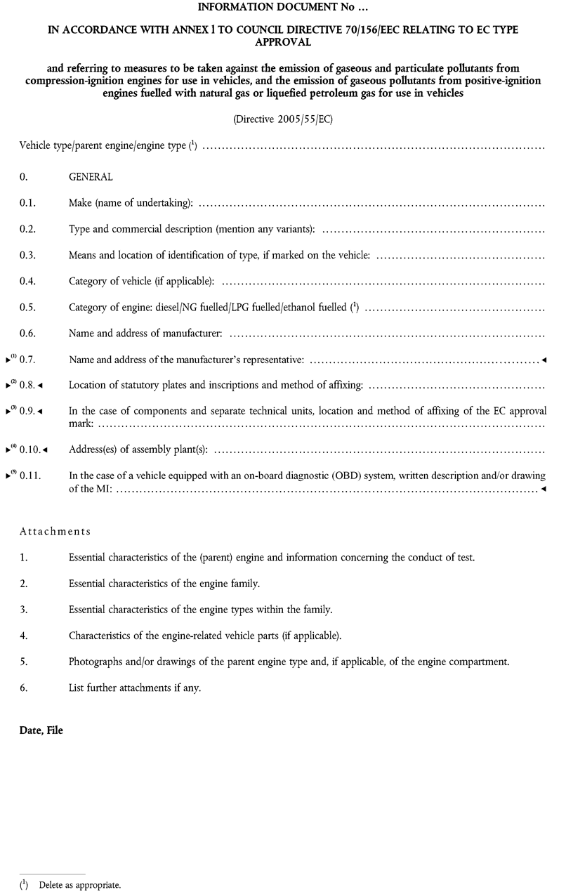
Appendix 1


Appendix 2ESSENTIAL CHARACTERISTICS OF THE ENGINE FAMILY

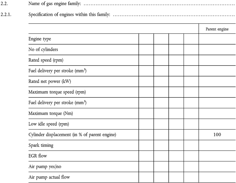
Appendix 3
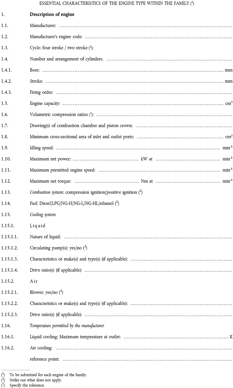


Appendix 4CHARACTERISTICS OF THE ENGINE-RELATED VEHICLE PARTS

[F2Appendix 5 OBD-RELATED INFORMATION
1. In accordance with the provisions of section 5 of Annex IV to Directive 2005/78/EC, the following additional information must be provided by the vehicle manufacturer for the purposes of enabling the manufacture of OBD-compatible replacement or service parts and diagnostic tools and test equipment, unless such information is covered by intellectual property rights or constitutes specific know-how of the manufacturer or the OEM supplier(s). U.K.
Where appropriate, the information given in this section shall be repeated in Appendix 2 to the EC type-approval certificate (Annex VI to this Directive):
1.1. A description of the type and number of the pre-conditioning cycles used for the original type approval of the vehicle. U.K.
1.2. A description of the type of the OBD demonstration cycle used for the original type-approval of the vehicle for the component monitored by the OBD system. U.K.
1.3. A comprehensive document describing all sensed components with the strategy for fault detection and MI activation (fixed number of driving cycles or statistical method), including a list of relevant secondary sensed parameters for each component monitored by the OBD system. A list of all OBD output codes and format used (with an explanation of each) associated with individual emission related powertrain components and individual non-emission related components, where monitoring of the component is used to determine MI activation. U.K.
1.3.1. The information required by this section may, for example, be defined by completing a table as follows, which shall be attached to this Annex: U.K.
| Component | Fault code | Monitoring strategy | Fault detection criteria | MI activation criteria | Secondary parameters | Preconditioning | Demonstration test |
|---|---|---|---|---|---|---|---|
| SCR catalyst | Pxxxx | NO x sensor 1 and 2 signals | Difference between sensor 1 and sensor 2 signals | 3 rd cycle | Engine speed, engine load, catalyst temperature, reagent activity | Three OBD test cycles (3 short ESC cycles) | OBD test cycle (short ESC cycle) |
1.3.2. The information required by this Appendix may be limited to the complete list of the fault codes recorded by the OBD system where section 5.1.2.1 of Annex IV to Directive 2005/78/EC is not applicable as in the case of replacement or service components. This information may, for example, be defined by completing the two first columns of the table of section 1.3.1 above. U.K.
The complete information package should be made available to the type-approval authority as part of the additional material requested in section 6.1.7.1 of Annex I to this Directive, ‘ documentation requirements ’ .
1.3.3. The information required by this section shall be repeated in Appendix 2 to the EC type-approval certificate (Annex VI to this Directive). U.K.
Where section 5.1.2.1 of Annex IV to Directive 2005/78/EC is not applicable in the case of replacement or service components, the information provided in Appendix 2 to the EC type-approval certificate (Annex VI to this Directive) can be limited to the one mentioned in section 1.3.2.]
ANNEX IIIU.K.TEST PROCEDURE
1.INTRODUCTIONU.K.
1.1.This Annex describes the methods of determining emissions of gaseous components, particulates and smoke from the engines to be tested. Three test cycles are described that shall be applied according to the provisions of Annex I, Section 6.2:U.K.
the ESC which consists of a steady state 13-mode cycle,
the ELR which consists of transient load steps at different speeds, which are integral parts of one test procedure, and are run concurrently,
the ETC which consists of a second-by-second sequence of transient modes.
1.2.The test shall be carried out with the engine mounted on a test bench and connected to a dynamometer.U.K.
1.3.Measurement principleU.K.
The emissions to be measured from the exhaust of the engine include the gaseous components (carbon monoxide, total hydrocarbons for diesel engines on the ESC test only; non-methane hydrocarbons for diesel and gas engines on the ETC test only; methane for gas engines on the ETC test only and oxides of nitrogen), the particulates (diesel engines only) and smoke (diesel engines on the ELR test only). Additionally, carbon dioxide is often used as a tracer gas for determining the dilution ratio of partial and full flow dilution systems. Good engineering practice recommends the general measurement of carbon dioxide as an excellent tool for the detection of measurement problems during the test run.
[F11.3.1. ESC Test U.K.
During a prescribed sequence of warmed-up engine operating conditions the amounts of the above exhaust emissions shall be examined continuously by taking a sample from the raw or diluted exhaust gas. The test cycle consists of a number of speed and power modes which cover the typical operating range of diesel engines. During each mode the concentration of each gaseous pollutant, exhaust flow and power output shall be determined, and the measured values weighted. For particulate measurement, the exhaust gas shall be diluted with conditioned ambient air using either a partial flow or full flow dilution system. The particulates shall be collected on a single suitable filter in proportion to the weighting factors of each mode. The grams of each pollutant emitted per kilowatt hour shall be calculated as described in Appendix 1 to this Annex. Additionally, NO x shall be measured at three test points within the control area selected by the Technical Service and the measured values compared to the values calculated from those modes of the test cycle enveloping the selected test points. The NO x control check ensures the effectiveness of the emission control of the engine within the typical engine operating range.]
1.3.2.ELR testU.K.
During a prescribed load response test, the smoke of a warmed-up engine shall be determined by means of an opacimeter. The test consists of loading the engine at constant speed from 10 % to 100 % load at three different engine speeds. Additionally, a fourth load step selected by the Technical Service(20) shall be run, and the value compared to the values of the previous load steps. The smoke peak shall be determined using an averaging algorithm, as described in Appendix 1 to this Annex.
[F11.3.3. ETC Test U.K.
During a prescribed transient cycle of warmed-up engine operating conditions, which is based closely on road-type-specific driving patterns of heavy-duty engines installed in trucks and buses, the above pollutants shall be examined either after diluting the total exhaust gas with conditioned ambient air (CVS system with double dilution for particulates) or by determining the gaseous components in the raw exhaust gas and the particulates with a partial flow dilution system. Using the engine torque and speed feedback signals of the engine dynamometer, the power shall be integrated with respect to time of the cycle resulting in the work produced by the engine over the cycle. For a CVS system, the concentration of NO x and HC shall be determined over the cycle by integration of the analyser signal, whereas the concentration of CO, CO 2 , and NMHC may be determined by integration of the analyser signal or by bag sampling. If measured in the raw exhaust gas, all gaseous components shall be determined over the cycle by integration of the analyser signal. For particulates, a proportional sample shall be collected on a suitable filter. The raw or diluted exhaust gas flow rate shall be determined over the cycle to calculate the mass emission values of the pollutants. The mass emission values shall be related to the engine work to get the grams of each pollutant emitted per kilowatt hour, as described in Appendix 2 to this Annex.]
2.TEST CONDITIONSU.K.
[F12.1. Engine Test Conditions U.K.
2.1.1. The absolute temperature ( T a ) of the engine air at the inlet to the engine expressed in Kelvin, and the dry atmospheric pressure ( p s ), expressed in kPa shall be measured and the parameter f a shall be determined according to the following provisions. In multi-cylinder engines having distinct groups of intake manifolds, for example, in a ‘V’ engine configuration, the average temperature of the distinct groups shall be taken. U.K.


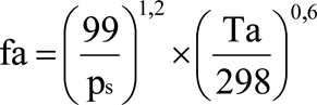
2.1.2. Test Validity U.K.
For a test to be recognised as valid, the parameter f a shall be such that:
0,96 ≤ f a ≤ 1,06]
2.2.Engines with charge air coolingU.K.
The charge air temperature shall be recorded and shall be, at the speed of the declared maximum power and full load, within ± 5 K of the maximum charge air temperature specified in Annex II, Appendix 1, Section 1.16.3. The temperature of the cooling medium shall be at least 293 K (20 °C).
If a test shop system or external blower is used, the charge air temperature shall be within ± 5 K of the maximum charge air temperature specified in Annex II, Appendix 1, Section 1.16.3 at the speed of the declared maximum power and full load. The setting of the charge air cooler for meeting the above conditions shall be used for the whole test cycle.
2.3.Engine air intake systemU.K.
An engine air intake system shall be used presenting an air intake restriction within ± 100 Pa of the upper limit of the engine operating at the speed at the declared maximum power and full load.
2.4.Engine exhaust systemU.K.
An exhaust system shall be used presenting an exhaust back pressure within ± 1 000 Pa of the upper limit of the engine operating at the speed of declared maximum power and full load and a volume within ± 40 % of that specified by the manufacturer. A test shop system may be used, provided it represents actual engine operating conditions. The exhaust system shall conform to the requirements for exhaust gas sampling, as set out in Annex III, Appendix 4, Section 3.4 and in Annex V, Section 2.2.1, EP and Section 2.3.1, EP.
If the engine is equipped with an exhaust aftertreatment device, the exhaust pipe must have the same diameter as found in-use for at least 4 pipe diameters upstream to the inlet of the beginning of the expansion section containing the aftertreatment device. The distance from the exhaust manifold flange or turbocharger outlet to the exhaust aftertreatment device shall be the same as in the vehicle configuration or within the distance specifications of the manufacturer. The exhaust backpressure or restriction shall follow the same criteria as above, and may be set with a valve. The aftertreatment container may be removed during dummy tests and during engine mapping, and replaced with an equivalent container having an inactive catalyst support.
2.5.Cooling systemU.K.
An engine cooling system with sufficient capacity to maintain the engine at normal operating temperatures prescribed by the manufacturer shall be used.
2.6.Lubricating oilU.K.
Specifications of the lubricating oil used for the test shall be recorded and presented with the results of the test, as specified in Annex II, Appendix 1, Section 7.1.
2.7.FuelU.K.
The fuel shall be the reference fuel specified in Annex IV.
The fuel temperature and measuring point shall be specified by the manufacturer within the limits given in Annex II, Appendix 1, Section 1.16.5. The fuel temperature shall not be lower than 306 K (33 °C). If not specified, it shall be 311 K ± 5 K (38 °C ± 5 °C) at the inlet to the fuel supply.
For NG and LPG fuelled engines, the fuel temperature and measuring point shall be within the limits given in Annex II, Appendix 1, Section 1.16.5 or in Annex II, Appendix 3, Section 1.16.5 in cases where the engine is not a parent engine.
[F12.8 If the engine is equipped with an exhaust aftertreatment system, the emissions measured on the test cycle shall be representative of the emissions in the field. In the case of an engine equipped with a exhaust aftertreatment system that requires the consumption of a reagent, the reagent used for all tests shall comply with section 2.2.1.13 of Appendix 1 to Annex II. U.K.
2.8.1. For an exhaust aftertreatment system based on a continuous regeneration process the emissions shall be measured on a stabilised aftertreatment system. U.K.
The regeneration process shall occur at least once during the ETC test and the manufacturer shall declare the normal conditions under which regeneration occurs (soot load, temperature, exhaust back-pressure, etc).
In order to verify the regeneration process at least 5 ETC tests shall be conducted. During the tests the exhaust temperature and pressure shall be recorded (temperature before and after the aftertreatment system, exhaust back pressure, etc).
The aftertreatment system is considered to be satisfactory if the conditions declared by the manufacturer occur during the test during a sufficient time.
The final test result shall be the arithmetic mean of the different ETC test results.
If the exhaust aftertreatment has a security mode that shifts to a periodic regeneration mode it should be checked following section 2.8.2. For that specific case the emission limits in table 2 of Annex I could be exceeded and would not be weighted.
2.8.2. For an exhaust aftertreatment based on a periodic regeneration process, the emissions shall be measured on at least two ETC tests, one during and one outside a regeneration event on a stabilised aftertreatment system, and the results be weighted. U.K.
The regeneration process shall occur at least once during the ETC test. The engine may be equipped with a switch capable of preventing or permitting the regeneration process provided this operation has no effect on the original engine calibration.
The manufacturer shall declare the normal parameter conditions under which the regeneration process occurs (soot load, temperature, exhaust back-pressure etc) and its duration time (n2). The manufacturer shall also provide all the data to determine the time between two regenerations (n1). The exact procedure to determine this time shall be agreed by the Technical Service based upon good engineering judgement.
The manufacturer shall provide an aftertreatment system that has been loaded in order to achieve regeneration during an ETC test. Regeneration shall not occur during this engine conditioning phase.
Average emissions between regeneration phases shall be determined from the arithmetic mean of several approximately equidistant ETC tests. It is recommended to run at least one ETC as close as possible prior to a regeneration test and one ETC immediately after a regeneration test. As an alternative, the manufacturer may provide data to show that the emissions remain constant (±15 %) between regeneration phases. In this case, the emissions of only one ETC test may be used.
During the regeneration test, all the data needed to detect regeneration shall be recorded (CO or NO x emissions, temperature before and after the aftertreatment system, exhaust back pressure etc).
During the regeneration process, the emission limits in table 2 of Annex I can be exceeded.
The measured emissions shall be weighted according to section 5.5 and 6.3 of Appendix 2 to this Annex and the final result shall not exceed the limits in table 2 of Annex I.]
Appendix 1ESC AND ELR TEST CYCLES
1.ENGINE AND DYNAMOMETER SETTINGSU.K.
1.1.Determination of engine speeds A, B and CU.K.
The engine speeds A, B and C shall be declared by the manufacturer in accordance with the following provisions:
The high speed nhi shall be determined by calculating 70 % of the declared maximum net power P(n), as determined in Annex II, Appendix 1, Section 8.2. The highest engine speed where this power value occurs on the power curve is defined as nhi.
The low speed nlo shall be determined by calculating 50 % of the declared maximum net power P(n), as determined in Annex II, Appendix 1, Section 8.2. The lowest engine speed where this power value occurs on the power curve is defined as nlo.
The engine speeds A, B and C shall be calculated as follows:


The engine speeds A, B and C may be verified by either of the following methods:
(a)
additional test points shall be measured during engine power approval according to Directive 80/1269/EEC for an accurate determination of nhi and nlo. The maximum power, nhi and nlo shall be determined from the power curve, and engine speeds A, B and C shall be calculated according to the above provisions;
(b)
the engine shall be mapped along the full load curve, from maximum no load speed to idle speed, using at least 5 measurement points per 1 000 rpm intervals and measurement points within ± 50 rpm of the speed at declared maximum power. The maximum power, nhi and nlo shall be determined from this mapping curve, and engine speeds A, B and C shall be calculated according to the above provisions.
If the measured engine speeds A, B and C are within ± 3 % of the engine speeds as declared by the manufacturer, the declared engine speeds shall be used for the emissions test. If the tolerance is exceeded for any of the engine speeds, the measured engine speeds shall be used for the emissions test.
1.2.Determination of dynamometer settingsU.K.
The torque curve at full load shall be determined by experimentation to calculate the torque values for the specified test modes under net conditions, as specified in Annex II, Appendix 1, Section 8.2. The power absorbed by engine-driven equipment, if applicable, shall be taken into account. The dynamometer setting for each test mode shall be calculated using the formula:


where:
s
=
dynamometer setting, kW
P(n)
=
net engine power as indicated in Annex II, Appendix 1, Section 8.2, kW
L
=
per cent load as indicated in Section 2.7.1, %
P(a)
=
power absorbed by auxiliaries to be fitted as indicated in Annex II, Appendix 1, Section 6.1
P(b)
=
power absorbed by auxiliaries to be removed as indicated in Annex II, Appendix 1, Section 6.2
2.ESC TEST RUNU.K.
At the manufacturers request, a dummy test may be run for conditioning of the engine and exhaust system before the measurement cycle.
[F12.1. Preparation of the Sampling Filter U.K.
At least one hour before the test, each filter shall be placed in a partially covered petri dish which is protected against dust contamination, and placed in a weighing chamber for stabilisation. At the end of the stabilisation period each filter shall be weighed and the tare weight shall be recorded. The filter shall then be stored in a closed petri dish or sealed filter holder until needed for testing. The filter shall be used within eight hours of its removal from the weighing chamber. The tare weight shall be recorded.]
2.2.Installation of the measuring equipmentU.K.
The instrumentation and sample probes shall be installed as required. When using a full flow dilution system for exhaust gas dilution, the tailpipe shall be connected to the system.
2.3.Starting the dilution system and the engineU.K.
The dilution system and the engine shall be started and warmed up until all temperatures and pressures have stabilised at maximum power according to the recommendation of the manufacturer and good engineering practice.
2.4.Starting the particulate sampling systemU.K.
The particulate sampling system shall be started and running on by-pass. The particulate background level of the dilution air may be determined by passing dilution air through the particulate filters. If filtered dilution air is used, one measurement may be done prior to or after the test. If the dilution air is not filtered, measurements at the beginning and at the end of the cycle, may be done, and the values averaged.
2.5.Adjustment of the dilution ratioU.K.
The dilution air shall be set such that the temperature of the diluted exhaust gas measured immediately prior to the primary filter shall not exceed 325 K (52 °C) at any mode. The dilution ratio (q) shall not be less than 4.
For systems that use CO2 or NOx concentration measurement for dilution ratio control, the CO2 or NOx content of the dilution air must be measured at the beginning and at the end of each test. The pre- and post-test background CO2 or NOx concentration measurements of the dilution air must be within 100 ppm or 5 ppm of each other, respectively.
2.6.Checking the analysersU.K.
The emission analysers shall be set at zero and spanned.
2.7.Test cycleU.K.
2.7.1.The following 13-mode cycle shall be followed in dynamometer operation on the test engineU.K.
| Mode number | Engine speed | Percent load | Weighting factor | Mode length |
|---|---|---|---|---|
| 1 | idle | — | 0,15 | 4 minutes |
| 2 | A | 100 | 0,08 | 2 minutes |
| 3 | B | 50 | 0,1 | 2 minutes |
| 4 | B | 75 | 0,1 | 2 minutes |
| 5 | A | 50 | 0,05 | 2 minutes |
| 6 | A | 75 | 0,05 | 2 minutes |
| 7 | A | 25 | 0,05 | 2 minutes |
| 8 | B | 100 | 0,09 | 2 minutes |
| 9 | B | 25 | 0,1 | 2 minutes |
| 10 | C | 100 | 0,08 | 2 minutes |
| 11 | C | 25 | 0,05 | 2 minutes |
| 12 | C | 75 | 0,05 | 2 minutes |
| 13 | C | 50 | 0,05 | 2 minutes |
2.7.2.Test sequenceU.K.
The test sequence shall be started. The test shall be performed in the order of the mode numbers as set out in Section 2.7.1.
The engine must be operated for the prescribed time in each mode, completing engine speed and load changes in the first 20 seconds. The specified speed shall be held to within ± 50 rpm and the specified torque shall be held to within ± 2 % of the maximum torque at the test speed.
At the manufacturers request, the test sequence may be repeated a sufficient number of times for sampling more particulate mass on the filter. The manufacturer shall supply a detailed description of the data evaluation and calculation procedures. The gaseous emissions shall only be determined on the first cycle.
2.7.3.Analyser responseU.K.
The output of the analysers shall be recorded on a strip chart recorder or measured with an equivalent data acquisition system with the exhaust gas flowing through the analysers throughout the test cycle.
[F12.7.4. Particulate Sampling U.K.
One filter shall be used for the complete test procedure. The modal weighting factors specified in the test cycle procedure shall be taken into account by taking a sample proportional to the exhaust mass flow during each individual mode of the cycle. This can be achieved by adjusting sample flow rate, sampling time, and/or dilution ratio, accordingly, so that the criterion for the effective weighting factors in section 5.6 is met.
The sampling time per mode must be at least 4 seconds per 0,01 weighting factor. Sampling must be conducted as late as possible within each mode. Particulate sampling shall be completed no earlier than 5 seconds before the end of each mode.]
2.7.5.Engine conditionsU.K.
The engine speed and load, intake air temperature and depression, exhaust temperature and backpressure, fuel flow and air or exhaust flow, charge air temperature, fuel temperature and humidity shall be recorded during each mode, with the speed and load requirements (see Section 2.7.2) being met during the time of particulate sampling, but in any case during the last minute of each mode.
Any additional data required for calculation shall be recorded (see Sections 4 and 5).
2.7.6.NOx check within the control areaU.K.
The NOx check within the control area shall be performed immediately upon completion of mode 13.
The engine shall be conditioned at mode 13 for a period of three minutes before the start of the measurements. Three measurements shall be made at different locations within the control area, selected by the Technical Service(21). The time for each measurement shall be 2 minutes.
The measurement procedure is identical to the NOx measurement on the 13-mode cycle, and shall be carried out in accordance with Sections 2.7.3, 2.7.5, and 4.1 of this Appendix, and Annex III, Appendix 4, Section 3.
The calculation shall be carried out in accordance with Section 4.
2.7.7.Rechecking the analysersU.K.
After the emission test a zero gas and the same span gas shall be used for rechecking. The test will be considered acceptable if the difference between the pre-test and post-test results is less than 2 % of the span gas value.
3.ELR TEST RUNU.K.
3.1.Installation of the measuring equipmentU.K.
The opacimeter and sample probes, if applicable, shall be installed after the exhaust silencer or any aftertreatment device, if fitted, according to the general installation procedures specified by the instrument manufacturer. Additionally, the requirements of Section 10 of ISO IDS 11614 shall be observed, where appropriate.
Prior to any zero and full scale checks, the opacimeter shall be warmed up and stabilised according to the instrument manufacturer's recommendations. If the opacimeter is equipped with a purge air system to prevent sooting of the meter optics, this system shall also be activated and adjusted according to the manufacturer's recommendations.
3.2.Checking of the opacimeterU.K.
The zero and full scale checks shall be made in the opacity readout mode, since the opacity scale offers two truly definable calibration points, namely 0 % opacity and 100 % opacity. The light absorption coefficient is then correctly calculated based upon the measured opacity and the LA, as submitted by the opacimeter manufacturer, when the instrument is returned to the k readout mode for testing.
With no blockage of the opacimeter light beam, the readout shall be adjusted to 0,0 % ± 1,0 % opacity. With the light being prevented from reaching the receiver, the readout shall be adjusted to 100,0 % ± 1,0 % opacity.
3.3.Test cycleU.K.
3.3.1.Conditioning of the engineU.K.
Warming up of the engine and the system shall be at maximum power in order to stabilise the engine parameters according to the recommendation of the manufacturer. The preconditioning phase should also protect the actual measurement against the influence of deposits in the exhaust system from a former test.
When the engine is stabilised, the cycle shall be started within 20 ± 2 s after the preconditioning phase. At the manufacturers request, a dummy test may be run for additional conditioning before the measurement cycle.
3.3.2.Test sequenceU.K.
The test consists of a sequence of three load steps at each of the three engine speeds A (cycle 1), B (cycle 2) and C (cycle 3) determined in accordance with Annex III, Section 1.1, followed by cycle 4 at a speed within the control area and a load between 10 % and 100 %, selected by the Technical Service(22). The following sequence shall be followed in dynamometer operation on the test engine, as shown in Figure 3.
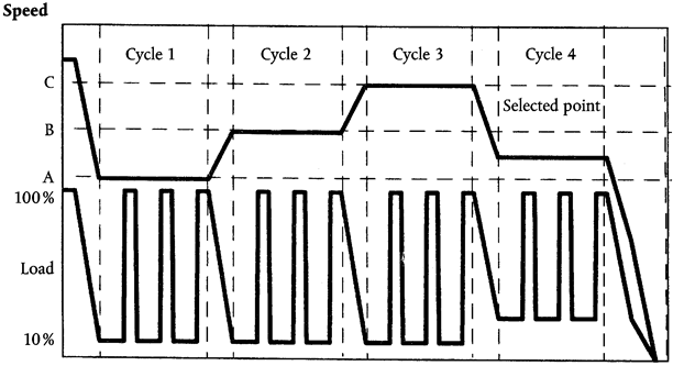
(a)
The engine shall be operated at engine speed A and 10 per cent load for 20 ± 2 s. The specified speed shall be held to within ± 20 rpm and the specified torque shall be held to within ± 2 % of the maximum torque at the test speed.
(b)
At the end of the previous segment, the speed control lever shall be moved rapidly to, and held in, the wide open position for 10 ± 1 s. The necessary dynamometer load shall be applied to keep the engine speed within ± 150 rpm during the first 3 s, and within ± 20 rpm during the rest of the segment.
(c)
The sequence described in (a) and (b) shall be repeated two times.
(d)
Upon completion of the third load step, the engine shall be adjusted to engine speed B and 10 per cent load within 20 ± 2 s.
(e)
The sequence (a) to (c) shall be run with the engine operating at engine speed B.
(f)
Upon completion of the third load step, the engine shall be adjusted to engine speed C and 10 per cent load within 20 ± 2 s.
(g)
The sequence (a) to (c) shall be run with the engine operating at engine speed C.
(h)
Upon completion of the third load step, the engine shall be adjusted to the selected engine speed and any load above 10 per cent within 20 ± 2 s.
(i)
The sequence (a) to (c) shall be run with the engine operating at the selected engine speed.
3.4.Cycle validationU.K.
The relative standard deviations of the mean smoke values at each test speed (SVA, SVB, SVC, as calculated in accordance with Section 6.3.3 of this Appendix from the three successive load steps at each test speed) shall be lower than 15 % of the mean value, or 10 % of the limit value shown in Table 1 of Annex I, whichever is greater. If the difference is greater, the sequence shall be repeated until three successive load steps meet the validation criteria.
3.5.Rechecking of the opacimeterU.K.
The post-test opacimeter zero drift value shall not exceed ± 5,0 % of the limit value shown in Table 1 of Annex I.
[F24. CALCULATION OF THE EXHAUST GAS FLOW U.K.
4.1. Determination of Raw Exhaust Gas Mass Flow U.K.
For calculation of the emissions in the raw exhaust, it is necessary to know the exhaust gas flow. The exhaust gas mass flow rate shall be determined in accordance with section 4.1.1 or 4.1.2. The accuracy of exhaust flow determination shall be ±2,5 % of reading or ±1,5 % of the engine's maximum value whichever is the greater. Equivalent methods (e.g. those described in section 4.2 of Appendix 2 to this Annex) may be used.
4.1.1. Direct measurement method U.K.
Direct measurement of the exhaust flow may be done by systems such as:
pressure differential devices, like flow nozzle,
ultrasonic flowmeter,
vortex flowmeter.
Precautions shall be taken to avoid measurement errors which will impact emission value errors. Such precautions include the careful installation of the device in the engine exhaust system according to the instrument manufacturers’ recommendations and to good engineering practice. Especially, engine performance and emissions shall not be affected by the installation of the device.
4.1.2. Air and fuel measurement method U.K.
This involves measurement of the air flow and the fuel flow. Air flowmeters and fuel flowmeters shall be used that meet the total accuracy requirement of section 4.1. The calculation of the exhaust gas flow is as follows:
q mew = q maw + q mf
4.2. Determination of Diluted Exhaust Gas Mass Flow U.K.
For calculation of the emissions in the diluted exhaust using a full flow dilution system it is necessary to know the diluted exhaust gas flow. The flow rate of the diluted exhaust ( q mdew ) shall be measured over each mode with a PDP-CVS, CFV-CVS or SSV-CVS in line with the general formulae given in section 4.1 of Appendix 2 to this Annex. The accuracy shall be ±2 % of reading or better, and shall be determined according to the provisions of section 2.4 of Appendix 5 to this Annex.]
[F15. CALCULATION OF THE GASEOUS EMISSIONS U.K.
5.1. Data Evaluation U.K.
For the evaluation of the gaseous emissions, the chart reading of the last 30 seconds of each mode shall be averaged and the average concentrations (conc) of HC, CO and NO x during each mode shall be determined from the average chart readings and the corresponding calibration data. A different type of recording can be used if it ensures an equivalent data acquisition.
For the NO x check within the control area, the above requirements apply for NO x only.
The exhaust gas flow q mew or the diluted exhaust gas flow q mdew , if used optionally, shall be determined in accordance with section 2.3 of Appendix 4 to this Annex.
5.2. Dry/Wet Correction U.K.
The measured concentration shall be converted to a wet basis according to the following formulae, if not already measured on a wet basis. The conversion shall be done for each individual mode.
c wet = k w × c dry
For the raw exhaust gas:

or

where:
p r
=
water vapour pressure after cooling bath, kPa,
p b
=
total atmospheric pressure, kPa,
H a
=
intake air humidity, g water per kg dry air,
k f
=
0,055584 × w ALF – 0,0001083 × w BET – 0,0001562 × w GAM + 0,0079936 × w DEL + 0,0069978 × w EPS
For the diluted exhaust gas:

or,
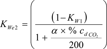
For the dilution air:
K Wd = 1 – K W1

For the intake air:
K Wa = 1 – K W2
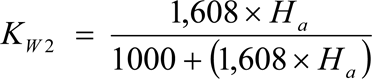
where:
H a
=
intake air humidity, g water per kg dry air
H d
=
dilution air humidity, g water per kg dry air
and may be derived from relative humidity measurement, dewpoint measurement, vapour pressure measurement or dry/wet bulb measurement using the generally accepted formulae.
5.3. NO x correction for humidity and temperature U.K.
As the NO x emission depends on ambient air conditions, the NO x concentration shall be corrected for ambient air temperature and humidity with the factors given in the following formulae. The factors are valid in the range between 0 and 25 g/kg dry air.
(a)
for compression ignition engines:

with:
T a
=
temperature of the intake air, K
H a
=
humidity of the intake air, g water per kg dry air
where:
H a may be derived from relative humidity measurement, dewpoint measurement, vapour pressure measurement or dry/wet bulb measurement using the generally accepted formulae.
(b)
for spark ignition engines
k h.G = 0,6272 + 44,030 × 10 –3 × H a - 0,862 × 10 –3 × H a 2
where:
H a may be derived from relative humidity measurement, dew point measurement, vapour pressure measurement or dry/wet bulb measurement using the generally accepted formulae.
5.4. Calculation of the emission mass flow rates U.K.
The emission mass flow rate (g/h) for each mode shall be calculated as follows. For the calculation of NO x , the humidity correction factor k h,D , or k h,G , as applicable, as determined according to section 5.3, shall be used.
The measured concentration shall be converted to a wet basis according to section 5.2 if not already measured on a wet basis. Values for u gas are given in Table 6 for selected components based on ideal gas properties and the fuels relevant for this Directive.
(a)
for the raw exhaust gas
m gas = u gas × c gas × q mew
where:
u gas
=
ratio between density of exhaust component and density of exhaust gas
c gas
=
concentration of the respective component in the raw exhaust gas, ppm
q mew
=
exhaust mass flow rate, kg/h
(b)
for the diluted gas
m gas = u gas × c gas,c × q mdew
where:
u gas
=
ratio between density of exhaust component and density of air
c gas,c
=
background corrected concentration of the respective component in the diluted exhaust gas, ppm
q mdew
=
diluted exhaust mass flow rate, kg/h
where:
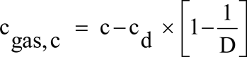
The dilution factor D shall be calculated according to section 5.4.1 of Appendix 2 to this Annex.
5.5. Calculation of the specific emissions U.K.
The emissions (g/kWh) shall be calculated for all individual components in the following way:

where:
m gas is the mass of individual gas
P n is the net power determined according to section 8.2 in Annex II.
The weighting factors used in the above calculation are according to section 2.7.1.
Table 6
Values of u gas in the raw and dilute exhaust gas for various exhaust components
| Notes: | ||||||
| ||||||
| Fuel | NO x | CO | THC/NMHC | CO 2 | CH 4 | |
|---|---|---|---|---|---|---|
| Diesel | Exhaust raw | 0,001587 | 0,000966 | 0,000479 | 0,001518 | 0,000553 |
| Exhaust dilute | 0,001588 | 0,000967 | 0,00048 | 0,001519 | 0,000553 | |
| Ethanol | Exhaust raw | 0,001609 | 0,00098 | 0,000805 | 0,001539 | 0,000561 |
| Exhaust dilute | 0,001588 | 0,000967 | 0,000795 | 0,001519 | 0,000553 | |
| CNG | Exhaust raw | 0,001622 | 0,000987 | 0,000523 | 0,001552 | 0,000565 |
| Exhaust dilute | 0,001588 | 0,000967 | 0,000584 | 0,001519 | 0,000553 | |
| Propane | Exhaust raw | 0,001603 | 0,000976 | 0,000511 | 0,001533 | 0,000559 |
| Exhaust dilute | 0,001588 | 0,000967 | 0,000507 | 0,001519 | 0,000553 | |
| Butane | Exhaust raw | 0,0016 | 0,000974 | 0,000505 | 0,00153 | 0,000558 |
| Exhaust dilute | 0,001588 | 0,000967 | 0,000501 | 0,001519 | 0,000553 | |
5.6. Calculation of the area control values U.K.
For the three control points selected according to section 2.7.6, the NO x emission shall be measured and calculated according to section 5.6.1 and also determined by interpolation from the modes of the test cycle closest to the respective control point according to section 5.6.2. The measured values are then compared to the interpolated values according to section 5.6.3.
5.6.1. Calculation of the Specific Emission U.K.
The NO x emission for each of the control points (Z) shall be calculated as follows:
m NOx,Z = 0,001587 × c NOx,Z × k h,D × q mew
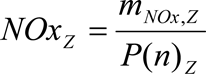
5.6.2. Determination of the Emission Value from the Test Cycle U.K.
The NO x emission for each of the control points shall be interpolated from the four closest modes of the test cycle that envelop the selected control point Z as shown in Figure 4. For these modes (R, S, T, U), the following definitions apply:
Speed(R) = Speed(T) = n RT
Speed(S) = Speed(U) = n SU
Per cent load(R) = Per cent load(S)
Per cent load(T) = Per cent load(U).
The NO x emission of the selected control point Z shall be calculated as follows:

and:
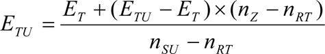


where:
E R , E S , E T , E U = specific NO x emission of the enveloping modes calculated in accordance with section 5.6.1.
M R , M S , M T , M U = engine torque of the enveloping modes.

5.6.3. Comparison of NO x Emission Values U.K.
The measured specific NO x emission of the control point Z (NO x,Z ) is compared to the interpolated value (E Z ) as follows:

6. CALCULATION OF THE PARTICULATE EMISSIONS U.K.
6.1. Data Evaluation U.K.
For the evaluation of the particulates, the total sample masses ( m sep ) through the filter shall be recorded for each mode.
The filter shall be returned to the weighing chamber and conditioned for at least one hour, but not more than 80 hours, and then weighed. The gross weight of the filters shall be recorded and the tare weight (see section 2.1) subtracted, which results in the particulate sample mass m f .
If background correction is to be applied, the dilution air mass ( m d ) through the filter and the particulate mass ( m f,d ) shall be recorded. If more than one measurement was made, the quotient m f,d / m d shall be calculated for each single measurement and the values averaged.
6.2. Partial Flow Dilution System U.K.
The final reported test results of the particulate emission shall be determined through the following steps. Since various types of dilution rate control may be used, different calculation methods for q medf apply. All calculations shall be based upon the average values of the individual modes during the sampling period.
6.2.1. Isokinetic systems U.K.
q medf = q mew × r d

where r a corresponds to the ratio of the cross sectional areas of the isokinetic probe and the exhaust pipe:

6.2.2. Systems with measurement of CO 2 or NO x concentration U.K.
q medf = q mew × r d

where:
c wE
=
wet concentration of the tracer gas in the raw exhaust
c wD
=
wet concentration of the tracer gas in the diluted exhaust
c wA
=
wet concentration of the tracer gas in the dilution air
Concentrations measured on a dry basis shall be converted to a wet basis according to section 5.2 of this Appendix.
6.2.3. Systems with CO 2 measurement and carbon balance method (23) U.K.
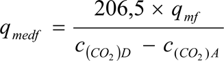
where:
c (CO2)D
=
CO 2 concentration of the diluted exhaust
c (CO2)A
=
CO 2 concentration of the dilution air
(concentrations in vol % on wet basis)
This equation is based upon the carbon balance assumption (carbon atoms supplied to the engine are emitted as CO 2 ) and determined through the following steps:
q medf = q mew × r d
and

6.2.4. Systems with flow measurement U.K.
q medf = q mew × r d

6.3. Full Flow Dilution System U.K.
All calculations shall be based upon the average values of the individual modes during the sampling period. The diluted exhaust gas flow q mdew shall be determined in accordance with section 4.1 of Appendix 2 to this Annex. The total sample mass m sep shall be calculated in accordance with section 6.2.1 of Appendix 2 to this Annex.
6.4. Calculation of the Particulate Mass Flow Rate U.K.
The particulate mass flow rate shall be calculated as follows. If a full flow dilution system is used, q medf as determined according to section 6.2 shall be replaced with q mdew as determined according to section 6.3.


i = 1, … n
The particulate mass flow rate may be background corrected as follows:
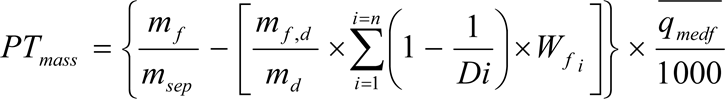
where D shall be calculated in accordance with section 5.4.1 of Appendix 2 to this Annex.]
[F17.] CALCULATION OF THE SMOKE VALUESU.K.
[F17.1.] Bessel algorithmU.K.
The Bessel algorithm shall be used to compute the 1 s average values from the instantaneous smoke readings, converted in accordance with Section 6.3.1. The algorithm emulates a low pass second order filter, and its use requires iterative calculations to determine the coefficients. These coefficients are a function of the response time of the opacimeter system and the sampling rate. Therefore, Section 6.1.1 must be repeated whenever the system response time and/or sampling rate changes.
[F1 7.1.1.] Calculation of filter response time and Bessel constantsU.K.
The required Bessel response time (tF) is a function of the physical and electrical response times of the opacimeter system, as specified in Annex III, Appendix 4, Section 5.2.4, and shall be calculated by the following equation:

where:
tp
=
physical response time, s
te
=
electrical response time, s
The calculations for estimating the filter cut-off frequency (fc) are based on a step input 0 to 1 in ≤ 0,01 s (see Annex VII). The response time is defined as the time between when the Bessel output reaches 10 % (t10) and when it reaches 90 % (t90) of this step function. This must be obtained by iterating on fc until t90-t10≈tF. The first iteration for fc is given by the following formula:

The Bessel constants E and K shall be calculated by the following equations:


where:
D
=
0,618034


[F1 7.1.2.] Calculation of the Bessel algorithmU.K.
Using the values of E and K, the 1 s Bessel averaged response to a step input Si shall be calculated as follows:

where:
Si-2
=
Si-1 = 0
Si
=
1
Yi-2
=
Yi-1 = 0
The times t10 and t90 shall be interpolated. The difference in time between t90 and t10 defines the response time tF for that value of fc. If this response time is not close enough to the required response time, iteration shall be continued until the actual response time is within 1 % of the required response as follows:

[F1 7.2.] Data evaluationU.K.
The smoke measurement values shall be sampled with a minimum rate of 20 Hz.
[F1 7.3.] Determination of smokeU.K.
[F1 7.3.1.] Data conversionU.K.
Since the basic measurement unit of all opacimeters is transmittance, the smoke values shall be converted from transmittance (τ) to the light absorption coefficient (k) as follows:

and

where:
k
=
light absorption coefficient, m-1
LA
=
effective optical path length, as submitted by instrument manufacturer, m
N
=
opacity, %
τ
=
transmittance, %
The conversion shall be applied, before any further data processing is made.
[F17.3.2.] Calculation of Bessel averaged smokeU.K.
The proper cut-off frequency fc is the one that produces the required filter response time tF. Once this frequency has been determined through the iterative process of Section 6.1.1, the proper Bessel algorithm constants E and K shall be calculated. The Bessel algorithm shall then be applied to the instantaneous smoke trace (k-value), as described in Section 6.1.2:

The Bessel algorithm is recursive in nature. Thus, it needs some initial input values of Si-1 and Si-2 and initial output values Yi-1 and Yi-2 to get the algorithm started. These may be assumed to be 0.
For each load step of the three speeds A, B and C, the maximum 1s value Ymax shall be selected from the individual Yi values of each smoke trace.
[F17.3.3.] Final resultU.K.
The mean smoke values (SV) from each cycle (test speed) shall be calculated as follows:
For test speed A
:
SVA = (Ymax1,A + Ymax2,A + Ymax3,A) / 3
For test speed B
:
SVB = (Ymax1,B + Ymax2,B + Ymax3,B) / 3
For test speed C
:
SVC = (Ymax1,C + Ymax2,C + Ymax3,C) / 3
where:
Ymax1, Ymax2, Ymax3
=
highest 1 s Bessel averaged smoke value at each of the three load steps
The final value shall be calculated as follows:
SV = (0,43 x SVA) + (0,56 x SVB) + (0,01 x SVC)
Appendix 2ETC TEST CYCLE
1.ENGINE MAPPING PROCEDUREU.K.
1.1.Determination of the mapping speed rangeU.K.
For generating the ETC on the test cell, the engine needs to be mapped prior to the test cycle for determining the speed vs torque curve. The minimum and maximum mapping speeds are defined as follows:
Minimum mapping speed
=
idle speed
Maximum mapping speed
=
nhi × 1,02 or speed where full load torque drops off to zero, whichever is lower
1.2.Performing the engine power mapU.K.
The engine shall be warmed up at maximum power in order to stabilise the engine parameters according to the recommendation of the manufacturer and good engineering practice. When the engine is stabilised, the engine map shall be performed as follows:
(a)
the engine shall be unloaded and operated at idle speed;
(b)
the engine shall be operated at full load setting of the injection pump at minimum mapping speed;
(c)
the engine speed shall be increased at an average rate of 8 ± 1 min-1 /s from minimum to maximum mapping speed. Engine speed and torque points shall be recorded at a sample rate of a least one point per second.
1.3.Mapping curve generationU.K.
All data points recorded under Section 1.2 shall be connected using linear interpolation between points. The resulting torque curve is the mapping curve and shall be used to convert the normalised torque values of the engine cycle into actual torque values for the test cycle, as described in Section 2.
1.4.Alternate mappingU.K.
If a manufacturer believes that the above mapping techniques are unsafe or unrepresentative for any given engine, alternate mapping techniques may be used. These alternate techniques must satisfy the intent of the specified mapping procedures to determine the maximum available torque at all engine speeds achieved during the test cycles. Deviations from the mapping techniques specified in this section for reasons of safety or representativeness shall be approved by the Technical Service along with the justification for their use. In no case, however, shall descending continual sweeps of engine speed be used for governed or turbocharged engines.
1.5.Replicate testsU.K.
An engine need not be mapped before each and every test cycle. An engine shall be remapped prior to a test cycle if:
an unreasonable amount of time has transpired since the last map, as determined by engineering judgement,
or
physical changes or recalibrations have been made to the engine which may potentially affect engine performance.
2.GENERATION OF THE REFERENCE TEST CYCLEU.K.
The transient test cycle is described in Appendix 3 to this Annex. The normalised values for torque and speed shall be changed to the actual values, as follows, resulting in the reference cycle.
2.1.Actual speedU.K.
The speed shall be unnormalised using the following equation:

The reference speed (nref) corresponds to the 100 % speed values specified in the engine dynamometer schedule of Appendix 3. It is defined as follows (see Figure 1 of Annex I):
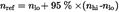
where nhi and nlo are either specified according to Annex I, Section 2 or determined according to Annex III, Appendix 1, Section 1.1.
2.2.Actual torqueU.K.
The torque is normalised to the maximum torque at the respective speed. The torque values of the reference cycle shall be unnormalised, using the mapping curve determined according to Section 1.3, as follows:
Actual torque = (% torque × max. torque/100)
for the respective actual speed as determined in Section 2.1.
The negative torque values of the motoring points (‘m’) shall take on, for purposes of reference cycle generation, unnormalised values determined in either of the following ways:
negative 40 % of the positive torque available at the associated speed point,
mapping of the negative torque required to motor the engine from minimum to maximum mapping speed,
determination of the negative torque required to motor the engine at idle and reference speeds and linear interpolation between these two points.
2.3.Example of the unnormalisation procedureU.K.
As an example, the following test point shall be unnormalised:
% speed
=
43
% torque
=
82
Given the following values:
reference speed
=
2 200 min-1
idle speed
=
600 min-1
results in,
actual speed = (43 × (2 200 - 600)/100) + 600 = 1 288 min-1
actual torque = (82 × 700/100) = 574 Nm
where the maximum torque observed from the mapping curve at 1 288 min-1 is 700 Nm.
[F13. EMISSIONS TEST RUN U.K.
At the manufacturers request, a dummy test may be run for conditioning of the engine and exhaust system before the measurement cycle.
NG and LPG fuelled engines shall be run-in using the ETC test. The engine shall be run over a minimum of two ETC cycles and until the CO emission measured over one ETC cycle does not exceed by more than 10 % the CO emission measured over the previous ETC cycle.
3.1. Preparation of the sampling filters (if applicable) U.K.
At least one hour before the test, each filter shall be placed in a partially covered petri dish, which is protected against dust contamination, and placed in a weighing chamber for stabilisation. At the end of the stabilisation period, each filter shall be weighed and the tare weight shall be recorded. The filter shall then be stored in a closed petri dish or sealed filter holder until needed for testing. The filter shall be used within eight hours of its removal from the weighing chamber. The tare weight shall be recorded.
3.2. Installation of the measuring equipment U.K.
The instrumentation and sample probes shall be installed as required. The tailpipe shall be connected to the full flow dilution system, if used.
3.3. Starting the dilution system and the engine U.K.
The dilution system and the engine shall be started and warmed up until all temperatures and pressures have stabilised at maximum power according to the recommendation of the manufacturer and good engineering practice.
3.4. Starting the particulate sampling system (diesel engines only) U.K.
The particulate sampling system shall be started and running on by-pass. The particulate background level of the dilution air may be determined by passing dilution air through the particulate filters. If filtered dilution air is used, one measurement may be done prior to or after the test. If the dilution air is not filtered, measurements at the beginning and at the end of the cycle may be done and the values averaged.
The dilution system and the engine shall be started and warmed up until all temperatures and pressures have stabilised according to the recommendation of the manufacturer and good engineering practice.
In case of periodic regeneration aftertreatment, the regeneration shall not occur during the warm-up of the engine.
3.5. Adjustment of the dilution system U.K.
The flow rates of the dilution system (full flow or partial flow) shall be set to eliminate water condensation in the system, and to obtain a maximum filter face temperature of 325 K (52 °C) or less (see section 2.3.1 of Annex V, DT).
3.6. Checking the analysers U.K.
The emission analysers shall be set at zero and spanned. If sample bags are used, they shall be evacuated.
3.7. Engine starting procedure U.K.
The stabilised engine shall be started according to the manufacturer's recommended starting procedure in the owner's manual, using either a production starter motor or the dynamometer. Optionally, the test may start directly from the engine preconditioning phase without shutting the engine off, when the engine has reached the idle speed.
3.8. Test cycle U.K.
3.8.1. Test sequence U.K.
The test sequence shall be started, if the engine has reached idle speed. The test shall be performed according to the reference cycle as set out in section 2 of this Appendix. Engine speed and torque command set points shall be issued at 5 Hz (10 Hz recommended) or greater. Feedback engine speed and torque shall be recorded at least once every second during the test cycle, and the signals may be electronically filtered.
3.8.2. Gaseous emissions measurement U.K.
3.8.2.1. Full flow dilution system U.K.
At the start of the engine or test sequence, if the cycle is started directly from the preconditioning, the measuring equipment shall be started, simultaneously:
start collecting or analysing dilution air,
start collecting or analysing diluted exhaust gas,
start measuring the amount of diluted exhaust gas (CVS) and the required temperatures and pressures,
start recording the feedback data of speed and torque of the dynamometer.
HC and NO x shall be measured continuously in the dilution tunnel with a frequency of 2 Hz. The average concentrations shall be determined by integrating the analyzer signals over the test cycle. The system response time shall be no greater than 20 s, and shall be coordinated with CVS flow fluctuations and sampling time/test cycle offsets, if necessary. CO, CO 2 , NMHC and CH 4 shall be determined by integration or by analysing the concentrations in the sample bag, collected over the cycle. The concentrations of the gaseous pollutants in the dilution air shall be determined by integration or by collecting into the background bag. All other values shall be recorded with a minimum of one measurement per second (1 Hz).
3.8.2.2. Raw exhaust measurement U.K.
At the start of the engine or test sequence, if the cycle is started directly from the preconditioning, the measuring equipment shall be started, simultaneously:
start analysing the raw exhaust gas concentrations,
start measuring the exhaust gas or intake air and fuel flow rate,
start recording the feedback data of speed and torque of the dynamometer.
For the evaluation of the gaseous emissions, the emission concentrations (HC, CO and NO x ) and the exhaust gas mass flow rate shall be recorded and stored with at least 2 Hz on a computer system. The system response time shall be no greater than 10 s. All other data may be recorded with a sample rate of at least 1 Hz. For analogue analysers the response shall be recorded, and the calibration data may be applied online or offline during the data evaluation.
For calculation of the mass emission of the gaseous components the traces of the recorded concentrations and the trace of the exhaust gas mass flow rate shall be time aligned by the transformation time as defined in section 2 of Annex I. Therefore, the response time of each gaseous emissions analyser and of the exhaust gas mass flow system shall be determined according to the provisions of section 4.2.1 and section 1.5 of Appendix 5 to this Annex and recorded.
3.8.3. Particulate sampling (if applicable) U.K.
3.8.3.1. Full flow dilution system U.K.
At the start of the engine or test sequence, if the cycle is started directly from the preconditioning, the particulate sampling system shall be switched from by-pass to collecting particulates.
If no flow compensation is used, the sample pump(s) shall be adjusted so that the flow rate through the particulate sample probe or transfer tube is maintained at a value within ±5 % of the set flow rate. If flow compensation (i.e., proportional control of sample flow) is used, it must be demonstrated that the ratio of main tunnel flow to particulate sample flow does not change by more than ±5 % of its set value (except for the first 10 seconds of sampling).
Note: For double dilution operation, sample flow is the net difference between the flow rate through the sample filters and the secondary dilution air flow rate. U.K.
The average temperature and pressure at the gas meter(s) or flow instrumentation inlet shall be recorded. If the set flow rate cannot be maintained over the complete cycle (within ±5 %) because of high particulate loading on the filter, the test shall be voided. The test shall be rerun using a lower flow rate and/or a larger diameter filter.
3.8.3.2. Partial flow dilution system U.K.
At the start of the engine or test sequence, if the cycle is started directly from the preconditioning, the particulate sampling system shall be switched from by-pass to collecting particulates.
For the control of a partial flow dilution system, a fast system response is required. The transformation time for the system shall be determined by the procedure in section 3.3 of Appendix 5 to Annex III. If the combined transformation time of the exhaust flow measurement (see section 4.2.1) and the partial flow system is less than 0,3 sec, online control may be used. If the transformation time exceeds 0,3 sec, look ahead control based on a pre-recorded test run must be used. In this case, the rise time shall be ≤ 1 sec and the delay time of the combination ≤ 10 sec.
The total system response shall be designed as to ensure a representative sample of the particulates, q mp,i , proportional to the exhaust mass flow. To determine the proportionality, a regression analysis of q mp,i versus q mew,i shall be conducted on a minimum 1 Hz data acquisition rate, and the following criteria shall be met:
The correlation coefficient R 2 of the linear regression between q mp,i and q mew,i shall not be less than 0,95,
The standard error of estimate of q mp,i on q mew,i shall not exceed 5 % of q mp maximum,
q mp intercept of the regression line shall not exceed ±2 % of q mp maximum.
Optionally, a pretest may be run, and the exhaust mass flow signal of the pretest be used for controlling the sample flow into the particulate system (look-ahead control). Such a procedure is required if the transformation time of the particulate system, t 50,P or the transformation time of the exhaust mass flow signal, t 50,F , or both, are > 0,3 sec. A correct control of the partial dilution system is obtained, if the time trace of q mew,pre of the pretest, which controls q mp , is shifted by a look-ahead time of t 50,P + t 50,F .
For establishing the correlation between q mp,i and q mew,i the data taken during the actual test shall be used, with q mew,i time aligned by t 50,F relative to q mp,i (no contribution from t 50,P to the time alignment). That is, the time shift between q mew and q mp is the difference in their transformation times that were determined in section 3.3 of Appendix 5 to Annex III.
3.8.4. Engine stalling U.K.
If the engine stalls anywhere during the test cycle, the engine shall be preconditioned and restarted, and the test repeated. If a malfunction occurs in any of the required test equipment during the test cycle, the test shall be voided.
3.8.5. Operations after test U.K.
At the completion of the test, the measurement of the diluted exhaust gas volume or raw exhaust gas flow rate, the gas flow into the collecting bags and the particulate sample pump shall be stopped. For an integrating analyser system, sampling shall continue until system response times have elapsed.
The concentrations of the collecting bags, if used, shall be analysed as soon as possible and in any case not later than 20 minutes after the end of the test cycle.
After the emission test, a zero gas and the same span gas shall be used for re-checking the analysers. The test will be considered acceptable if the difference between the pre-test and post-test results is less than 2 % of the span gas value.
3.9. Verification of the test run U.K.
3.9.1. Data shift U.K.
To minimise the biasing effect of the time lag between the feedback and reference cycle values, the entire engine speed and torque feedback signal sequence may be advanced or delayed in time with respect to the reference speed and torque sequence. If the feedback signals are shifted, both speed and torque must be shifted the same amount in the same direction.
3.9.2. Calculation of the cycle work U.K.
The actual cycle work W act (kWh) shall be calculated using each pair of engine feedback speed and torque values recorded. This shall be done after any feedback data shift has occurred, if this option is selected. The actual cycle work W act is used for comparison to the reference cycle work W ref and for calculating the brake specific emissions (see sections 4.4 and 5.2). The same methodology shall be used for integrating both reference and actual engine power. If values are to be determined between adjacent reference or adjacent measured values, linear interpolation shall be used.
In integrating the reference and actual cycle work, all negative torque values shall be set equal to zero and included. If integration is performed at a frequency of less than 5 Hertz, and if, during a given time segment, the torque value changes from positive to negative or negative to positive, the negative portion shall be computed and set equal to zero. The positive portion shall be included in the integrated value.
W act shall be between –15 % and +5 % of W ref
3.9.3. Validation statistics of the test cycle U.K.
Linear regressions of the feedback values on the reference values shall be performed for speed, torque and power. This shall be done after any feedback data shift has occurred, if this option is selected. The method of least squares shall be used, with the best fit equation having the form:
y = mx + b
where:
y
=
Feedback (actual) value of speed (min -1 ), torque (Nm), or power (kW)
m
=
slope of the regression line
x
=
reference value of speed (min -1 ), torque (Nm), or power (kW)
b
=
y intercept of the regression line
The standard error of estimate (SE) of y on x and the coefficient of determination (r 2 ) shall be calculated for each regression line.
It is recommended that this analysis be performed at 1 Hertz. All negative reference torque values and the associated feedback values shall be deleted from the calculation of cycle torque and power validation statistics. For a test to be considered valid, the criteria of table 7 must be met.
Table 7
Regression line tolerances
| a Until 1 October 2005 , the figures shown in brackets may be used for the type-approval testing of gas engines. (The Commission shall report on the development of gas engine technology to confirm or modify the regression line tolerances applicable to gas engines given in this table.) | |||
| Speed | Torque | Power | |
|---|---|---|---|
| Standard error of estimate (SE) of Y on X | Max 100 min –1 | Max 13 % (15 %) a of power map maximum engine torque | Max 8 % (15 %) a of power map maximum engine power |
| Slope of the regression line, m | 0,95 to 1,03 | 0,83 – 1,03 | 0,89 – 1,03 ( 0,83 – 1,03 ) a |
| Coefficient of determination, r 2 | min 0,97 (min 0,95 ) a | min 0,88 (min 0,75 ) a | min 0,91 (min 0,75 ) a |
| Y intercept of the regression line, b | ±50 min –1 | ±20 Nm or ±2 % (±20 Nm or ±3 %) a of max torque whichever is greater | ±4 kW or ±2 % (±4kW or ±3 %) a of max power whichever is greater |
Point deletions from the regression analyses are permitted where noted in Table 8.
Table 8
Permitted point deletions from regression analysis
| Conditions | Points to be deleted |
|---|---|
| Full load demand and torque feedback < 95 % torque reference | Torque and/or power |
| Full load demand and speed feedback < 95 % speed reference | Speed and/or power |
| No load, not an idle point, and torque feedback > torque reference | Torque and/or power |
| No load, speed feedback ≤ idle speed +50 min –1 and torque feedback = manufacturer defined/measured idle torque ±2 % of max. torque | Speed and/or power |
| No load, speed feedback > idle speed +50 min –1 and torque feedback > 105 % torque reference | Torque and/or power |
| No load and speed feedback > 105 % speed reference | Speed and/or power] |
[F24. CALCULATION OF THE EXHAUST GAS FLOW U.K.
4.1. Determination of the diluted exhaust gas flow U.K.
The total diluted exhaust gas flow over the cycle (kg/test) shall be calculated from the measurement values over the cycle and the corresponding calibration data of the flow measurement device ( V 0 for PDP, K V for CFV, C d for SSV), as determined in section 2 of Appendix 5 to Annex III). The following formulae shall be applied, if the temperature of the diluted exhaust is kept constant over the cycle by using a heat exchanger (±6 K for a PDP-CVS, ±11 K for a CFV-CVS or ±11 K for a SSV-CVS), see section 2.3 of Annex V).
For the PDP-CVS system:
m ed = 1,293 × V 0 × N P × ( p b - p 1 ) × 273 / (101,3 × T )
where:
V 0
=
volume of gas pumped per revolution under test conditions, m 3 /rev
N P
=
total revolutions of pump per test
p b
=
atmospheric pressure in the test cell, kPa
p 1
=
pressure depression below atmospheric at pump inlet, kPa
T
=
average temperature of the diluted exhaust gas at pump inlet over the cycle, K
For the CFV-CVS system:
m ed = 1,293 × t × K v × p p / T 0,5
where:
t
=
cycle time, s
K v
=
calibration coefficient of the critical flow venturi for standard conditions,
p p
=
absolute pressure at venturi inlet, kPa
T
=
absolute temperature at venturi inlet, K
For the SSV-CVS system
m ed = 1,293 × Q SSV
where:

with:

d
=
diameter of the SSV throat, m
C d
=
discharge coefficient of the SSV
p p
=
absolute pressure at venturi inlet, kPa
T
=
temperature at the venturi inlet, K


If a system with flow compensation is used (i.e. without heat exchanger), the instantaneous mass emissions shall be calculated and integrated over the cycle. In this case, the instantaneous mass of the diluted exhaust gas shall be calculated as follows.
For the PDP-CVS system:
m ed,i = 1,293 × V 0 × N P,i × ( p b - p 1 ) × 273 / (101,3 × T )
where:
N P,i = total revolutions of pump per time interval
For the CFV-CVS system:
m ed,i = 1,293 × Δ t i × K V × p p / T 0,5
where:
Δ t i = time interval, s
For the SSV-CVS system:
m ed = 1,293 × Q SSV × Δt i
where:
Δ t i = time interval, s
The real time calculation shall be initialised with either a reasonable value for C d , such as 0,98, or a reasonable value of Q ssv . If the calculation is initialised with Q ssv , the initial value of Q ssv shall be used to evaluate Re.
During all emissions tests, the Reynolds number at the SSV throat must be in the range of Reynolds numbers used to derive the calibration curve developed in section 2.4 of Appendix 5 to this Annex.
4.2. Determination of raw exhaust gas mass flow U.K.
For calculation of the emissions in the raw exhaust gas and for controlling of a partial flow dilution system, it is necessary to know the exhaust gas mass flow rate. For the determination of the exhaust mass flow rate, either of the methods described in sections 4.2.2 to 4.2.5 may be used.
4.2.1. Response time U.K.
For the purpose of emissions calculation, the response time of either method described below shall be equal to or less than the requirement for the analyzer response time, as defined in section 1.5 of Appendix 5 to this Annex.
For the purpose of controlling of a partial flow dilution system, a faster response is required. For partial flow dilution systems with online control, a response time of ≤ 0,3 seconds is required. For partial flow dilution systems with look ahead control based on a pre-recorded test run, a response time of the exhaust flow measurement system of ≤ 5 seconds with a rise time of ≤ 1 second is required. The system response time shall be specified by the instrument manufacturer. The combined response time requirements for exhaust gas flow and partial flow dilution system are indicated in section 3.8.3.2.
4.2.2. Direct measurement method U.K.
Direct measurement of the instantaneous exhaust flow may be done by systems such as:
pressure differential devices, like flow nozzle,
ultrasonic flowmeter,
vortex flowmeter.
Precautions shall be taken to avoid measurement errors which will impact emission value errors. Such precautions include the careful installation of the device in the engine exhaust system according to the instrument manufacturers' recommendations and to good engineering practice. Engine performance and emissions shall especially not be affected by the installation of the device.
The accuracy of exhaust flow determination shall be at least ±2,5 % of reading or ±1,5 % of engine's maximum value, whichever is the greater.
4.2.3. Air and fuel measurement method U.K.
This involves measurement of the air flow and the fuel flow. Air flowmeters and fuel flowmeters shall be used that meet the total exhaust flow accuracy requirement of section 4.2.2. The calculation of the exhaust gas flow is as follows:
q mew = q maw + q mf
4.2.4. Tracer measurement method U.K.
This involves measurement of the concentration of a tracer gas in the exhaust. A known amount of an inert gas (e.g. pure helium) shall be injected into the exhaust gas flow as a tracer. The gas is mixed and diluted by the exhaust gas, but shall not react in the exhaust pipe. The concentration of the gas shall then be measured in the exhaust gas sample.
In order to ensure complete mixing of the tracer gas, the exhaust gas sampling probe shall be located at least 1 m or 30 times the diameter of the exhaust pipe, whichever is larger, downstream of the tracer gas injection point. The sampling probe may be located closer to the injection point if complete mixing is verified by comparing the tracer gas concentration with the reference concentration when the tracer gas is injected upstream of the engine.
The tracer gas flow rate shall be set so that the tracer gas concentration at engine idle speed after mixing becomes lower than the full scale of the trace gas analyser.
The calculation of the exhaust gas flow is as follows:
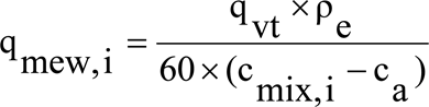
where:
q mew,i
=
instantaneous exhaust mass flow, kg/s
q v t
=
tracer gas flow, cm 3 /min
c mix.i
=
instantaneous concentration of the tracer gas after mixing, ppm
ρ e
=
density of the exhaust gas, kg/m 3 (cf. table 3)
c a
=
background concentration of the tracer gas in the intake air, ppm
When the background concentration is less than 1 % of the concentration of the tracer gas after mixing ( c mix.i ) at maximum exhaust flow, the background concentration may be neglected.
The total system shall meet the accuracy specifications for the exhaust gas flow, and shall be calibrated according to section 1.7 of Appendix 5 to this Annex.
4.2.5. Air flow and air-to-fuel ratio measurement method U.K.
This involves exhaust mass calculation from the air flow and the air to fuel ratio. The calculation of the instantaneous exhaust gas mass flow is as follows:

with:

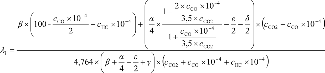
where:
A/F st
=
stoichiometric air to fuel ratio, kg/kg
λ
=
excess air ratio
c CO2
=
dry CO 2 concentration, %
c CO
=
dry CO concentration, ppm
c HC
=
HC concentration, ppm
Note: β can be 1 for fuels containing carbon and 0 for hydrogen fuel. U.K.
The air flowmeter shall meet the accuracy specifications of section 2.2 of Appendix 4 to this Annex, the CO 2 analyser used shall meet the specifications of section 3.3.2 of Appendix 4 to this Annex and the total system shall meet the accuracy specifications for the exhaust gas flow.
Optionally, air to fuel ratio measurement equipment such as a zirconia type sensor may be used for the measurement of the excess air ratio which meets the specifications of section 3.3.6 of Appendix 4 to this Annex.]
[F15. CALCULATION OF THE GASEOUS EMISSIONS U.K.
5.1. Data evaluation U.K.
For the evaluation of the gaseous emissions in the diluted exhaust gas, the emission concentrations (HC, CO and NO x ) and the diluted exhaust gas mass flow rate shall be recorded according to section 3.8.2.1 and stored on a computer system. For analogue analysers the response shall be recorded, and the calibration data may be applied online or offline during the data evaluation.
For the evaluation of the gaseous emissions in the raw exhaust gas, the emission concentrations (HC, CO and NO x ) and the exhaust gas mass flow rate shall be recorded according to section 3.8.2.2 and stored on a computer system. For analogue analysers the response shall be recorded, and the calibration data may be applied online or offline during the data evaluation.
5.2. Dry/wet correction U.K.
If the concentration is measured on a dry basis, it shall be converted to a wet basis according to the following formula. For continuous measurement, the conversion shall be applied to each instantaneous measurement before any further calculation.
c wet = k W × c dry
The conversion equations of section 5.2 of Appendix 1 to this Annex shall apply.
5.3. NO x correction for humidity and temperature U.K.
As the NO x emission depends on ambient air conditions, the NO x concentration shall be corrected for ambient air temperature and humidity with the factors given in section 5.3 of Appendix 1 to this Annex. The factors are valid in the range between 0 and 25 g/kg dry air.
5.4. Calculation of the emission mass flow rates U.K.
The emission mass over the cycle (g/test) shall be calculated as follows depending on the measurement method applied. The measured concentration shall be converted to a wet basis according to section 5.2 of Appendix 1 to this Annex, if not already measured on a wet basis. The respective values for u gas shall be applied that are given in Table 6 of Appendix 1 to this Annex for selected components based on ideal gas properties and the fuels relevant for this Directive.
(a)
for the raw exhaust gas:

where:
u gas
=
ratio between density of exhaust component and density of exhaust gas from table 6
c gas,i
=
instantaneous concentration of the respective component in the raw exhaust gas, ppm
q mew,i
=
instantaneous exhaust mass flow rate, kg/s
f
=
data sampling rate, Hz
n
=
number of measurements
(b)
for the diluted exhaust gas without flow compensation:
m gas = u gas × c gas × m ed
where:
u gas
=
ratio between density of exhaust component and density of air from table 6
c gas
=
average background corrected concentration of the respective component, ppm
m ed
=
total diluted exhaust mass over the cycle, kg
(c)
for the diluted exhaust gas with flow compensation:

where:
c e,i
=
instantaneous concentration of the respective component measured in the diluted exhaust gas, ppm
c d
=
concentration of the respective component measured in the dilution air, ppm
q mdew,i
=
instantaneous diluted exhaust gas mass flow rate, kg/s
m ed
=
total mass of diluted exhaust gas over the cycle, kg
u gas
=
ratio between density of exhaust component and density of air from table 6
D
=
dilution factor (see section 5.4.1)
If applicable, the concentration of NMHC and CH 4 shall be calculated by either of the methods shown in section 3.3.4 of Appendix 4 to this Annex, as follows:


5.4.1. Determination of the background corrected concentrations (full flow dilution system, only) U.K.
The average background concentration of the gaseous pollutants in the dilution air shall be subtracted from measured concentrations to get the net concentrations of the pollutants. The average values of the background concentrations can be determined by the sample bag method or by continuous measurement with integration. The following formula shall be used.

where:
c e
=
concentration of the respective pollutant measured in the diluted exhaust gas, ppm
c d
=
concentration of the respective pollutant measured in the dilution air, ppm
D
=
dilution factor
The dilution factor shall be calculated as follows:
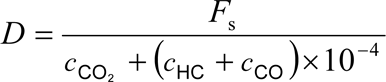
(b)
for NG fueled gas engines

where:
c CO2
=
concentration of CO 2 in the diluted exhaust gas, % vol
c HC
=
concentration of HC in the diluted exhaust gas, ppm C1
c NMHC
=
concentration of NMHC in the diluted exhaust gas, ppm C1
c CO
=
concentration of CO in the diluted exhaust gas, ppm
F S
=
stoichiometric factor
Concentrations measured on dry basis shall be converted to a wet basis in accordance with section 5.2 of Appendix 1 to this Annex.
The stoichiometric factor shall be calculated as follows:
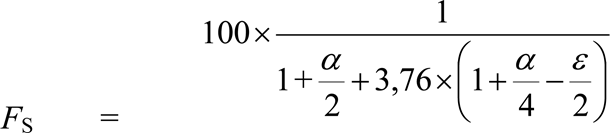
where:
α, ε are the molar ratios referring to a fuel CH α O ε
Alternatively, if the fuel composition is not known, the following stoichiometric factors may be used:
F S (diesel)
=
13,4
F S (LPG)
=
11,6
F S (NG)
=
9,5
5.5. Calculation of the specific emissions U.K.
The emissions (g/kWh) shall be calculated in the following way:
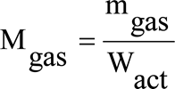

5.5.1. In case of a periodic exhaust aftertreatment system, the emissions shall be weighted as follows: U.K.

where:
n1
=
number of ETC tests between two regenerations
n2
=
number of ETC during a regeneration (minimum of one ETC test)
M gas,n2
=
emissions during a regeneration
M gas,n1
=
emissions after a regeneration.
6. CALCULATION OF THE PARTICULATE EMISSION (IF APPLICABLE) U.K.
6.1. Data evaluation U.K.
The particulate filter shall be returned to the weighing chamber no later than one hour after completion of the test. It shall be conditioned in a partially covered petri dish, which is protected against dust contamination, for at least one hour, but not more than 80 hours, and then weighed. The gross weight of the filters shall be recorded and the tare weight subtracted, which results in the particulate sample mass m f . For the evaluation of the particulate concentration, the total sample mass ( m sep ) through the filters over the test cycle shall be recorded.
If background correction is to be applied, the dilution air mass ( m d ) through the filter and the particulate mass ( m f,d ) shall be recorded.
6.2. Calculation of the mass flow U.K.
6.2.1. Full flow dilution system U.K.
The particulate mass (g/test) shall be calculated as follows:

where:
m f
=
particulate mass sampled over the cycle, mg
m sep
=
mass of diluted exhaust gas passing the particulate collection filters, kg
m ed
=
mass of diluted exhaust gas over the cycle, kg
If a double dilution system is used, the mass of the secondary dilution air shall be subtracted from the total mass of the double diluted exhaust gas sampled through the particulate filters.
m sep = m set – m ssd
where:
m set
=
mass of double diluted exhaust gas through particulate filter, kg
m ssd
=
mass of secondary dilution air, kg
If the particulate background level of the dilution air is determined in accordance with section 3.4, the particulate mass may be background corrected. In this case, the particulate mass (g/test) shall be calculated as follows:

where:
m PT , m sep , m ed
=
see above
m d
=
mass of primary dilution air sampled by background particulate sampler, kg
m f,d
=
mass of the collected background particulates of the primary dilution air, mg
D
=
dilution factor as determined in section 5.4.1.
6.2.2. Partial flow dilution system U.K.
The mass of particulates (g/test) shall be calculated by either of the following methods:
(a)

where:
m f
=
particulate mass sampled over the cycle, mg
m sep
=
mass of diluted exhaust gas passing the particulate collection filters, kg
m edf
=
mass of equivalent diluted exhaust gas over the cycle, kg
The total mass of equivalent diluted exhaust gas mass over the cycle shall be determined as follows:


where:
q m edf,i
=
instantaneous equivalent diluted exhaust mass flow rate, kg/s
q m ew,i
=
instantaneous exhaust mass flow rate, kg/s
r d,i
=
instantaneous dilution ratio
q m dew,i
=
instantaneous diluted exhaust mass flow rate through dilution tunnel, kg/s
q m dw,i
=
instantaneous dilution air mass flow rate, kg/s
f
=
data sampling rate, Hz
n
=
number of measurements
(b)

where:
m f
=
particulate mass sampled over the cycle, mg
r s
=
average sample ratio over the test cycle
with:
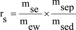
where:
m se
=
sample mass over the cycle, kg
m ew
=
total exhaust mass flow over the cycle, kg
m sep
=
mass of diluted exhaust gas passing the particulate collection filters, kg
m sed
=
mass of diluted exhaust gas passing the dilution tunnel, kg.
Note: In case of the total sampling type system, m sep and M sed are identical. U.K.
6.3. Calculation of the Specific Emission U.K.
The particulate emission (g/kWh) shall be calculated in the following way:

where:
W act = actual cycle work as determined according to section 3.9.2, kWh.
6.3.1. In case of a periodic regeneration aftertreatment system, the emissions shall be weighted as follows: U.K.

where:
n1
=
number of ETC tests between two regeneration events
n2
=
number of ETC tests during a regeneration (minimum of one ETC)


Appendix 3
ETC ENGINE DYNAMOMETER SCHEDULE
| ‘m’ = motoring. | ||
| Times | Normal speed% | Normal torque% |
|---|---|---|
| 1 | 0 | 0 |
| 2 | 0 | 0 |
| 3 | 0 | 0 |
| 4 | 0 | 0 |
| 5 | 0 | 0 |
| 6 | 0 | 0 |
| 7 | 0 | 0 |
| 8 | 0 | 0 |
| 9 | 0 | 0 |
| 10 | 0 | 0 |
| 11 | 0 | 0 |
| 12 | 0 | 0 |
| 13 | 0 | 0 |
| 14 | 0 | 0 |
| 15 | 0 | 0 |
| 16 | 0,1 | 1,5 |
| 17 | 23,1 | 21,5 |
| 18 | 12,6 | 28,5 |
| 19 | 21,8 | 71 |
| 20 | 19,7 | 76,8 |
| 21 | 54,6 | 80,9 |
| 22 | 71,3 | 4,9 |
| 23 | 55,9 | 18,1 |
| 24 | 72 | 85,4 |
| 25 | 86,7 | 61,8 |
| 26 | 51,7 | 0 |
| 27 | 53,4 | 48,9 |
| 28 | 34,2 | 87,6 |
| 29 | 45,5 | 92,7 |
| 30 | 54,6 | 99,5 |
| 31 | 64,5 | 96,8 |
| 32 | 71,7 | 85,4 |
| 33 | 79,4 | 54,8 |
| 34 | 89,7 | 99,4 |
| 35 | 57,4 | 0 |
| 36 | 59,7 | 30,6 |
| 37 | 90,1 | ‘m’ |
| 38 | 82,9 | ‘m’ |
| 39 | 51,3 | ‘m’ |
| 40 | 28,5 | ‘m’ |
| 41 | 29,3 | ‘m’ |
| 42 | 26,7 | ‘m’ |
| 43 | 20,4 | ‘m’ |
| 44 | 14,1 | 0 |
| 45 | 6,5 | 0 |
| 46 | 0 | 0 |
| 47 | 0 | 0 |
| 48 | 0 | 0 |
| 49 | 0 | 0 |
| 50 | 0 | 0 |
| 51 | 0 | 0 |
| 52 | 0 | 0 |
| 53 | 0 | 0 |
| 54 | 0 | 0 |
| 55 | 0 | 0 |
| 56 | 0 | 0 |
| 57 | 0 | 0 |
| 58 | 0 | 0 |
| 59 | 0 | 0 |
| 60 | 0 | 0 |
| 61 | 0 | 0 |
| 62 | 25,5 | 11,1 |
| 63 | 28,5 | 20,9 |
| 64 | 32 | 73,9 |
| 65 | 4 | 82,3 |
| 66 | 34,5 | 80,4 |
| 67 | 64,1 | 86 |
| 68 | 58 | 0 |
| 69 | 50,3 | 83,4 |
| 70 | 66,4 | 99,1 |
| 71 | 81,4 | 99,6 |
| 72 | 88,7 | 73,4 |
| 73 | 52,5 | 0 |
| 74 | 46,4 | 58,5 |
| 75 | 48,6 | 90,9 |
| 76 | 55,2 | 99,4 |
| 77 | 62,3 | 99 |
| 78 | 68,4 | 91,5 |
| 79 | 74,5 | 73,7 |
| 80 | 38 | 0 |
| 81 | 41,8 | 89,6 |
| 82 | 47,1 | 99,2 |
| 83 | 52,5 | 99,8 |
| 84 | 56,9 | 80,8 |
| 85 | 58,3 | 11,8 |
| 86 | 56,2 | ‘m’ |
| 87 | 52 | ‘m’ |
| 88 | 43,3 | ‘m’ |
| 89 | 36,1 | ‘m’ |
| 90 | 27,6 | ‘m’ |
| 91 | 21,1 | ‘m’ |
| 92 | 8 | 0 |
| 93 | 0 | 0 |
| 94 | 0 | 0 |
| 95 | 0 | 0 |
| 96 | 0 | 0 |
| 97 | 0 | 0 |
| 98 | 0 | 0 |
| 99 | 0 | 0 |
| 100 | 0 | 0 |
| 101 | 0 | 0 |
| 102 | 0 | 0 |
| 103 | 0 | 0 |
| 104 | 0 | 0 |
| 105 | 0 | 0 |
| 106 | 0 | 0 |
| 107 | 0 | 0 |
| 108 | 11,6 | 14,8 |
| 109 | 0 | 0 |
| 110 | 27,2 | 74,8 |
| 111 | 17 | 76,9 |
| 112 | 36 | 78 |
| 113 | 59,7 | 86 |
| 114 | 80,8 | 17,9 |
| 115 | 49,7 | 0 |
| 116 | 65,6 | 86 |
| 117 | 78,6 | 72,2 |
| 118 | 64,9 | ‘m’ |
| 119 | 44,3 | ‘m’ |
| 120 | 51,4 | 83,4 |
| 121 | 58,1 | 97 |
| 122 | 69,3 | 99,3 |
| 123 | 72 | 20,8 |
| 124 | 72,1 | ‘m’ |
| 125 | 65,3 | ‘m’ |
| 126 | 64 | ‘m’ |
| 127 | 59,7 | ‘m’ |
| 128 | 52,8 | ‘m’ |
| 129 | 45,9 | ‘m’ |
| 130 | 38,7 | ‘m’ |
| 131 | 32,4 | ‘m’ |
| 132 | 27 | ‘m’ |
| 133 | 21,7 | ‘m’ |
| 134 | 19,1 | 0,4 |
| 135 | 34,7 | 14 |
| 136 | 16,4 | 48,6 |
| 137 | 0 | 11,2 |
| 138 | 1,2 | 2,1 |
| 139 | 30,1 | 19,3 |
| 140 | 30 | 73,9 |
| 141 | 54,4 | 74,4 |
| 142 | 77,2 | 55,6 |
| 143 | 58,1 | 0 |
| 144 | 45 | 82,1 |
| 145 | 68,7 | 98,1 |
| 146 | 85,7 | 67,2 |
| 147 | 60,2 | 0 |
| 148 | 59,4 | 98 |
| 149 | 72,7 | 99,6 |
| 150 | 79,9 | 45 |
| 151 | 44,3 | 0 |
| 152 | 41,5 | 84,4 |
| 153 | 56,2 | 98,2 |
| 154 | 65,7 | 99,1 |
| 155 | 74,4 | 84,7 |
| 156 | 54,4 | 0 |
| 157 | 47,9 | 89,7 |
| 158 | 54,5 | 99,5 |
| 159 | 62,7 | 96,8 |
| 160 | 62,3 | 0 |
| 161 | 46,2 | 54,2 |
| 162 | 44,3 | 83,2 |
| 163 | 48,2 | 13,3 |
| 164 | 51 | ‘m’ |
| 165 | 50 | ‘m’ |
| 166 | 49,2 | ‘m’ |
| 167 | 49,3 | ‘m’ |
| 168 | 49,9 | ‘m’ |
| 169 | 51,6 | ‘m’ |
| 170 | 49,7 | ‘m’ |
| 171 | 48,5 | ‘m’ |
| 172 | 50,3 | 72,5 |
| 173 | 51,1 | 84,5 |
| 174 | 54,6 | 64,8 |
| 175 | 56,6 | 76,5 |
| 176 | 58 | ‘m’ |
| 177 | 53,6 | ‘m’ |
| 178 | 40,8 | ‘m’ |
| 179 | 32,9 | ‘m’ |
| 180 | 26,3 | ‘m’ |
| 181 | 20,9 | ‘m’ |
| 182 | 10 | 0 |
| 183 | 0 | 0 |
| 184 | 0 | 0 |
| 185 | 0 | 0 |
| 186 | 0 | 0 |
| 187 | 0 | 0 |
| 188 | 0 | 0 |
| 189 | 0 | 0 |
| 190 | 0 | 0 |
| 191 | 0 | 0 |
| 192 | 0 | 0 |
| 193 | 0 | 0 |
| 194 | 0 | 0 |
| 195 | 0 | 0 |
| 196 | 0 | 0 |
| 197 | 0 | 0 |
| 198 | 0 | 0 |
| 199 | 0 | 0 |
| 200 | 0 | 0 |
| 201 | 0 | 0 |
| 202 | 0 | 0 |
| 203 | 0 | 0 |
| 204 | 0 | 0 |
| 205 | 0 | 0 |
| 206 | 0 | 0 |
| 207 | 0 | 0 |
| 208 | 0 | 0 |
| 209 | 0 | 0 |
| 210 | 0 | 0 |
| 211 | 0 | 0 |
| 212 | 0 | 0 |
| 213 | 0 | 0 |
| 214 | 0 | 0 |
| 215 | 0 | 0 |
| 216 | 0 | 0 |
| 217 | 0 | 0 |
| 218 | 0 | 0 |
| 219 | 0 | 0 |
| 220 | 0 | 0 |
| 221 | 0 | 0 |
| 222 | 0 | 0 |
| 223 | 0 | 0 |
| 224 | 0 | 0 |
| 225 | 21,2 | 62,7 |
| 226 | 30,8 | 75,1 |
| 227 | 5,9 | 82,7 |
| 228 | 34,6 | 80,3 |
| 229 | 59,9 | 87 |
| 230 | 84,3 | 86,2 |
| 231 | 68,7 | ‘m’ |
| 232 | 43,6 | ‘m’ |
| 233 | 41,5 | 85,4 |
| 234 | 49,9 | 94,3 |
| 235 | 60,8 | 99 |
| 236 | 70,2 | 99,4 |
| 237 | 81,1 | 92,4 |
| 238 | 49,2 | 0 |
| 239 | 56 | 86,2 |
| 240 | 56,2 | 99,3 |
| 241 | 61,7 | 99 |
| 242 | 69,2 | 99,3 |
| 243 | 74,1 | 99,8 |
| 244 | 72,4 | 8,4 |
| 245 | 71,3 | 0 |
| 246 | 71,2 | 9,1 |
| 247 | 67,1 | ‘m’ |
| 248 | 65,5 | ‘m’ |
| 249 | 64,4 | ‘m’ |
| 250 | 62,9 | 25,6 |
| 251 | 62,2 | 35,6 |
| 252 | 62,9 | 24,4 |
| 253 | 58,8 | ‘m’ |
| 254 | 56,9 | ‘m’ |
| 255 | 54,5 | ‘m’ |
| 256 | 51,7 | 17 |
| 257 | 56,2 | 78,7 |
| 258 | 59,5 | 94,7 |
| 259 | 65,5 | 99,1 |
| 260 | 71,2 | 99,5 |
| 261 | 76,6 | 99,9 |
| 262 | 79 | 0 |
| 263 | 52,9 | 97,5 |
| 264 | 53,1 | 99,7 |
| 265 | 59 | 99,1 |
| 266 | 62,2 | 99 |
| 267 | 65 | 99,1 |
| 268 | 69 | 83,1 |
| 269 | 69,9 | 28,4 |
| 270 | 70,6 | 12,5 |
| 271 | 68,9 | 8,4 |
| 272 | 69,8 | 9,1 |
| 273 | 69,6 | 7 |
| 274 | 65,7 | ‘m’ |
| 275 | 67,1 | ‘m’ |
| 276 | 66,7 | ‘m’ |
| 277 | 65,6 | ‘m’ |
| 278 | 64,5 | ‘m’ |
| 279 | 62,9 | ‘m’ |
| 280 | 59,3 | ‘m’ |
| 281 | 54,1 | ‘m’ |
| 282 | 51,3 | ‘m’ |
| 283 | 47,9 | ‘m’ |
| 284 | 43,6 | ‘m’ |
| 285 | 39,4 | ‘m’ |
| 286 | 34,7 | ‘m’ |
| 287 | 29,8 | ‘m’ |
| 288 | 20,9 | 73,4 |
| 289 | 36,9 | ‘m’ |
| 290 | 35,5 | ‘m’ |
| 291 | 20,9 | ‘m’ |
| 292 | 49,7 | 11,9 |
| 293 | 42,5 | ‘m’ |
| 294 | 32 | ‘m’ |
| 295 | 23,6 | ‘m’ |
| 296 | 19,1 | 0 |
| 297 | 15,7 | 73,5 |
| 298 | 25,1 | 76,8 |
| 299 | 34,5 | 81,4 |
| 300 | 44,1 | 87,4 |
| 301 | 52,8 | 98,6 |
| 302 | 63,6 | 99 |
| 303 | 73,6 | 99,7 |
| 304 | 62,2 | ‘m’ |
| 305 | 29,2 | ‘m’ |
| 306 | 46,4 | 22 |
| 307 | 47,3 | 13,8 |
| 308 | 47,2 | 12,5 |
| 309 | 47,9 | 11,5 |
| 310 | 47,8 | 35,5 |
| 311 | 49,2 | 83,3 |
| 312 | 52,7 | 96,4 |
| 313 | 57,4 | 99,2 |
| 314 | 61,8 | 99 |
| 315 | 66,4 | 60,9 |
| 316 | 65,8 | ‘m’ |
| 317 | 59 | ‘m’ |
| 318 | 50,7 | ‘m’ |
| 319 | 41,8 | ‘m’ |
| 320 | 34,7 | ‘m’ |
| 321 | 28,7 | ‘m’ |
| 322 | 25,2 | ‘m’ |
| 323 | 43 | 24,8 |
| 324 | 38,7 | 0 |
| 325 | 48,1 | 31,9 |
| 326 | 40,3 | 61 |
| 327 | 42,4 | 52,1 |
| 328 | 46,4 | 47,7 |
| 329 | 46,9 | 30,7 |
| 330 | 46,1 | 23,1 |
| 331 | 45,7 | 23,2 |
| 332 | 45,5 | 31,9 |
| 333 | 46,4 | 73,6 |
| 334 | 51,3 | 60,7 |
| 335 | 51,3 | 51,1 |
| 336 | 53,2 | 46,8 |
| 337 | 53,9 | 50 |
| 338 | 53,4 | 52,1 |
| 339 | 53,8 | 45,7 |
| 340 | 50,6 | 22,1 |
| 341 | 47,8 | 26 |
| 342 | 41,6 | 17,8 |
| 343 | 38,7 | 29,8 |
| 344 | 35,9 | 71,6 |
| 345 | 34,6 | 47,3 |
| 346 | 34,8 | 80,3 |
| 347 | 35,9 | 87,2 |
| 348 | 38,8 | 90,8 |
| 349 | 41,5 | 94,7 |
| 350 | 47,1 | 99,2 |
| 351 | 53,1 | 99,7 |
| 352 | 46,4 | 0 |
| 353 | 42,5 | 0,7 |
| 354 | 43,6 | 58,6 |
| 355 | 47,1 | 87,5 |
| 356 | 54,1 | 99,5 |
| 357 | 62,9 | 99 |
| 358 | 72,6 | 99,6 |
| 359 | 82,4 | 99,5 |
| 360 | 88 | 99,4 |
| 361 | 46,4 | 0 |
| 362 | 53,4 | 95,2 |
| 363 | 58,4 | 99,2 |
| 364 | 61,5 | 99 |
| 365 | 64,8 | 99 |
| 366 | 68,1 | 99,2 |
| 367 | 73,4 | 99,7 |
| 368 | 73,3 | 29,8 |
| 369 | 73,5 | 14,6 |
| 370 | 68,3 | 0 |
| 371 | 45,4 | 49,9 |
| 372 | 47,2 | 75,7 |
| 373 | 44,5 | 9 |
| 374 | 47,8 | 10,3 |
| 375 | 46,8 | 15,9 |
| 376 | 46,9 | 12,7 |
| 377 | 46,8 | 8,9 |
| 378 | 46,1 | 6,2 |
| 379 | 46,1 | ‘m’ |
| 380 | 45,5 | ‘m’ |
| 381 | 44,7 | ‘m’ |
| 382 | 43,8 | ‘m’ |
| 383 | 41 | ‘m’ |
| 384 | 41,1 | 6,4 |
| 385 | 38 | 6,3 |
| 386 | 35,9 | 0,3 |
| 387 | 33,5 | 0 |
| 388 | 53,1 | 48,9 |
| 389 | 48,3 | ‘m’ |
| 390 | 49,9 | ‘m’ |
| 391 | 48 | ‘m’ |
| 392 | 45,3 | ‘m’ |
| 393 | 41,6 | 3,1 |
| 394 | 44,3 | 79 |
| 395 | 44,3 | 89,5 |
| 396 | 43,4 | 98,8 |
| 397 | 44,3 | 98,9 |
| 398 | 43 | 98,8 |
| 399 | 42,2 | 98,8 |
| 400 | 42,7 | 98,8 |
| 401 | 45 | 99 |
| 402 | 43,6 | 98,9 |
| 403 | 42,2 | 98,8 |
| 404 | 44,8 | 99 |
| 405 | 43,4 | 98,8 |
| 406 | 45 | 99 |
| 407 | 42,2 | 54,3 |
| 408 | 61,2 | 31,9 |
| 409 | 56,3 | 72,3 |
| 410 | 59,7 | 99,1 |
| 411 | 62,3 | 99 |
| 412 | 67,9 | 99,2 |
| 413 | 69,5 | 99,3 |
| 414 | 73,1 | 99,7 |
| 415 | 77,7 | 99,8 |
| 416 | 79,7 | 99,7 |
| 417 | 82,5 | 99,5 |
| 418 | 85,3 | 99,4 |
| 419 | 86,6 | 99,4 |
| 420 | 89,4 | 99,4 |
| 421 | 62,2 | 0 |
| 422 | 52,7 | 96,4 |
| 423 | 50,2 | 99,8 |
| 424 | 49,3 | 99,6 |
| 425 | 52,2 | 99,8 |
| 426 | 51,3 | 100 |
| 427 | 51,3 | 100 |
| 428 | 51,1 | 100 |
| 429 | 51,1 | 100 |
| 430 | 51,8 | 99,9 |
| 431 | 51,3 | 100 |
| 432 | 51,1 | 100 |
| 433 | 51,3 | 100 |
| 434 | 52,3 | 99,8 |
| 435 | 52,9 | 99,7 |
| 436 | 53,8 | 99,6 |
| 437 | 51,7 | 99,9 |
| 438 | 53,5 | 99,6 |
| 439 | 52 | 99,8 |
| 440 | 51,7 | 99,9 |
| 441 | 53,2 | 99,7 |
| 442 | 54,2 | 99,5 |
| 443 | 55,2 | 99,4 |
| 444 | 53,8 | 99,6 |
| 445 | 53,1 | 99,7 |
| 446 | 55 | 99,4 |
| 447 | 57 | 99,2 |
| 448 | 61,5 | 99 |
| 449 | 59,4 | 5,7 |
| 450 | 59 | 0 |
| 451 | 57,3 | 59,8 |
| 452 | 64,1 | 99 |
| 453 | 70,9 | 90,5 |
| 454 | 58 | 0 |
| 455 | 41,5 | 59,8 |
| 456 | 44,1 | 92,6 |
| 457 | 46,8 | 99,2 |
| 458 | 47,2 | 99,3 |
| 459 | 51 | 100 |
| 460 | 53,2 | 99,7 |
| 461 | 53,1 | 99,7 |
| 462 | 55,9 | 53,1 |
| 463 | 53,9 | 13,9 |
| 464 | 52,5 | ‘m’ |
| 465 | 51,7 | ‘m’ |
| 466 | 51,5 | 52,2 |
| 467 | 52,8 | 80 |
| 468 | 54,9 | 95 |
| 469 | 57,3 | 99,2 |
| 470 | 60,7 | 99,1 |
| 471 | 62,4 | ‘m’ |
| 472 | 60,1 | ‘m’ |
| 473 | 53,2 | ‘m’ |
| 474 | 44 | ‘m’ |
| 475 | 35,2 | ‘m’ |
| 476 | 30,5 | ‘m’ |
| 477 | 26,5 | ‘m’ |
| 478 | 22,5 | ‘m’ |
| 479 | 20,4 | ‘m’ |
| 480 | 19,1 | ‘m’ |
| 481 | 19,1 | ‘m’ |
| 482 | 13,4 | ‘m’ |
| 483 | 6,7 | ‘m’ |
| 484 | 3,2 | ‘m’ |
| 485 | 14,3 | 63,8 |
| 486 | 34,1 | 0 |
| 487 | 23,9 | 75,7 |
| 488 | 31,7 | 79,2 |
| 489 | 32,1 | 19,4 |
| 490 | 35,9 | 5,8 |
| 491 | 36,6 | 0,8 |
| 492 | 38,7 | ‘m’ |
| 493 | 38,4 | ‘m’ |
| 494 | 39,4 | ‘m’ |
| 495 | 39,7 | ‘m’ |
| 496 | 40,5 | ‘m’ |
| 497 | 40,8 | ‘m’ |
| 498 | 39,7 | ‘m’ |
| 499 | 39,2 | ‘m’ |
| 500 | 38,7 | ‘m’ |
| 501 | 32,7 | ‘m’ |
| 502 | 30,1 | ‘m’ |
| 503 | 21,9 | ‘m’ |
| 504 | 12,8 | 0 |
| 505 | 0 | 0 |
| 506 | 0 | 0 |
| 507 | 0 | 0 |
| 508 | 0 | 0 |
| 509 | 0 | 0 |
| 510 | 0 | 0 |
| 511 | 0 | 0 |
| 512 | 0 | 0 |
| 513 | 0 | 0 |
| 514 | 30,5 | 25,6 |
| 515 | 19,7 | 56,9 |
| 516 | 16,3 | 45,1 |
| 517 | 27,2 | 4,6 |
| 518 | 21,7 | 1,3 |
| 519 | 29,7 | 28,6 |
| 520 | 36,6 | 73,7 |
| 521 | 61,3 | 59,5 |
| 522 | 40,8 | 0 |
| 523 | 36,6 | 27,8 |
| 524 | 39,4 | 80,4 |
| 525 | 51,3 | 88,9 |
| 526 | 58,5 | 11,1 |
| 527 | 60,7 | ‘m’ |
| 528 | 54,5 | ‘m’ |
| 529 | 51,3 | ‘m’ |
| 530 | 45,5 | ‘m’ |
| 531 | 40,8 | ‘m’ |
| 532 | 38,9 | ‘m’ |
| 533 | 36,6 | ‘m’ |
| 534 | 36,1 | 72,7 |
| 535 | 44,8 | 78,9 |
| 536 | 51,6 | 91,1 |
| 537 | 59,1 | 99,1 |
| 538 | 66 | 99,1 |
| 539 | 75,1 | 99,9 |
| 540 | 81 | 8 |
| 541 | 39,1 | 0 |
| 542 | 53,8 | 89,7 |
| 543 | 59,7 | 99,1 |
| 544 | 64,8 | 99 |
| 545 | 70,6 | 96,1 |
| 546 | 72,6 | 19,6 |
| 547 | 72 | 6,3 |
| 548 | 68,9 | 0,1 |
| 549 | 67,7 | ‘m’ |
| 550 | 66,8 | ‘m’ |
| 551 | 64,3 | 16,9 |
| 552 | 64,9 | 7 |
| 553 | 63,6 | 12,5 |
| 554 | 63 | 7,7 |
| 555 | 64,4 | 38,2 |
| 556 | 63 | 11,8 |
| 557 | 63,6 | 0 |
| 558 | 63,3 | 5 |
| 559 | 60,1 | 9,1 |
| 560 | 61 | 8,4 |
| 561 | 59,7 | 0,9 |
| 562 | 58,7 | ‘m’ |
| 563 | 56 | ‘m’ |
| 564 | 53,9 | ‘m’ |
| 565 | 52,1 | ‘m’ |
| 566 | 49,9 | ‘m’ |
| 567 | 46,4 | ‘m’ |
| 568 | 43,6 | ‘m’ |
| 569 | 40,8 | ‘m’ |
| 570 | 37,5 | ‘m’ |
| 571 | 27,8 | ‘m’ |
| 572 | 17,1 | 0,6 |
| 573 | 12,2 | 0,9 |
| 574 | 11,5 | 1,1 |
| 575 | 8,7 | 0,5 |
| 576 | 8 | 0,9 |
| 577 | 5,3 | 0,2 |
| 578 | 4 | 0 |
| 579 | 3,9 | 0 |
| 580 | 0 | 0 |
| 581 | 0 | 0 |
| 582 | 0 | 0 |
| 583 | 0 | 0 |
| 584 | 0 | 0 |
| 585 | 0 | 0 |
| 586 | 0 | 0 |
| 587 | 8,7 | 22,8 |
| 588 | 16,2 | 49,4 |
| 589 | 23,6 | 56 |
| 590 | 21,1 | 56,1 |
| 591 | 23,6 | 56 |
| 592 | 46,2 | 68,8 |
| 593 | 68,4 | 61,2 |
| 594 | 58,7 | ‘m’ |
| 595 | 31,6 | ‘m’ |
| 596 | 19,9 | 8,8 |
| 597 | 32,9 | 70,2 |
| 598 | 43 | 79 |
| 599 | 57,4 | 98,9 |
| 600 | 72,1 | 73,8 |
| 601 | 53 | 0 |
| 602 | 48,1 | 86 |
| 603 | 56,2 | 99 |
| 604 | 65,4 | 98,9 |
| 605 | 72,9 | 99,7 |
| 606 | 67,5 | ‘m’ |
| 607 | 39 | ‘m’ |
| 608 | 41,9 | 38,1 |
| 609 | 44,1 | 80,4 |
| 610 | 46,8 | 99,4 |
| 611 | 48,7 | 99,9 |
| 612 | 50,5 | 99,7 |
| 613 | 52,5 | 90,3 |
| 614 | 51 | 1,8 |
| 615 | 50 | ‘m’ |
| 616 | 49,1 | ‘m’ |
| 617 | 47 | ‘m’ |
| 618 | 43,1 | ‘m’ |
| 619 | 39,2 | ‘m’ |
| 620 | 40,6 | 0,5 |
| 621 | 41,8 | 53,4 |
| 622 | 44,4 | 65,1 |
| 623 | 48,1 | 67,8 |
| 624 | 53,8 | 99,2 |
| 625 | 58,6 | 98,9 |
| 626 | 63,6 | 98,8 |
| 627 | 68,5 | 99,2 |
| 628 | 72,2 | 89,4 |
| 629 | 77,1 | 0 |
| 630 | 57,8 | 79,1 |
| 631 | 60,3 | 98,8 |
| 632 | 61,9 | 98,8 |
| 633 | 63,8 | 98,8 |
| 634 | 64,7 | 98,9 |
| 635 | 65,4 | 46,5 |
| 636 | 65,7 | 44,5 |
| 637 | 65,6 | 3,5 |
| 638 | 49,1 | 0 |
| 639 | 50,4 | 73,1 |
| 640 | 50,5 | ‘m’ |
| 641 | 51 | ‘m’ |
| 642 | 49,4 | ‘m’ |
| 643 | 49,2 | ‘m’ |
| 644 | 48,6 | ‘m’ |
| 645 | 47,5 | ‘m’ |
| 646 | 46,5 | ‘m’ |
| 647 | 46 | 11,3 |
| 648 | 45,6 | 42,8 |
| 649 | 47,1 | 83 |
| 650 | 46,2 | 99,3 |
| 651 | 47,9 | 99,7 |
| 652 | 49,5 | 99,9 |
| 653 | 50,6 | 99,7 |
| 654 | 51 | 99,6 |
| 655 | 53 | 99,3 |
| 656 | 54,9 | 99,1 |
| 657 | 55,7 | 99 |
| 658 | 56 | 99 |
| 659 | 56,1 | 9,3 |
| 660 | 55,6 | ‘m’ |
| 661 | 55,4 | ‘m’ |
| 662 | 54,9 | 51,3 |
| 663 | 54,9 | 59,8 |
| 664 | 54 | 39,3 |
| 665 | 53,8 | ‘m’ |
| 666 | 52 | ‘m’ |
| 667 | 50,4 | ‘m’ |
| 668 | 50,6 | 0 |
| 669 | 49,3 | 41,7 |
| 670 | 50 | 73,2 |
| 671 | 50,4 | 99,7 |
| 672 | 51,9 | 99,5 |
| 673 | 53,6 | 99,3 |
| 674 | 54,6 | 99,1 |
| 675 | 56 | 99 |
| 676 | 55,8 | 99 |
| 677 | 58,4 | 98,9 |
| 678 | 59,9 | 98,8 |
| 679 | 60,9 | 98,8 |
| 680 | 63 | 98,8 |
| 681 | 64,3 | 98,9 |
| 682 | 64,8 | 64 |
| 683 | 65,9 | 46,5 |
| 684 | 66,2 | 28,7 |
| 685 | 65,2 | 1,8 |
| 686 | 65 | 6,8 |
| 687 | 63,6 | 53,6 |
| 688 | 62,4 | 82,5 |
| 689 | 61,8 | 98,8 |
| 690 | 59,8 | 98,8 |
| 691 | 59,2 | 98,8 |
| 692 | 59,7 | 98,8 |
| 693 | 61,2 | 98,8 |
| 694 | 62,2 | 49,4 |
| 695 | 62,8 | 37,2 |
| 696 | 63,5 | 46,3 |
| 697 | 64,7 | 72,3 |
| 698 | 64,7 | 72,3 |
| 699 | 65,4 | 77,4 |
| 700 | 66,1 | 69,3 |
| 701 | 64,3 | ‘m’ |
| 702 | 64,3 | ‘m’ |
| 703 | 63 | ‘m’ |
| 704 | 62,2 | ‘m’ |
| 705 | 61,6 | ‘m’ |
| 706 | 62,4 | ‘m’ |
| 707 | 62,2 | ‘m’ |
| 708 | 61 | ‘m’ |
| 709 | 58,7 | ‘m’ |
| 710 | 55,5 | ‘m’ |
| 711 | 51,7 | ‘m’ |
| 712 | 49,2 | ‘m’ |
| 713 | 48,8 | 40,4 |
| 714 | 47,9 | ‘m’ |
| 715 | 46,2 | ‘m’ |
| 716 | 45,6 | 9,8 |
| 717 | 45,6 | 34,5 |
| 718 | 45,5 | 37,1 |
| 719 | 43,8 | ‘m’ |
| 720 | 41,9 | ‘m’ |
| 721 | 41,3 | ‘m’ |
| 722 | 41,4 | ‘m’ |
| 723 | 41,2 | ‘m’ |
| 724 | 41,8 | ‘m’ |
| 725 | 41,8 | ‘m’ |
| 726 | 43,2 | 17,4 |
| 727 | 45 | 29 |
| 728 | 44,2 | ‘m’ |
| 729 | 43,9 | ‘m’ |
| 730 | 38 | 10,7 |
| 731 | 56,8 | ‘m’ |
| 732 | 57,1 | ‘m’ |
| 733 | 52 | ‘m’ |
| 734 | 44,4 | ‘m’ |
| 735 | 40,2 | ‘m’ |
| 736 | 39,2 | 16,5 |
| 737 | 38,9 | 73,2 |
| 738 | 39,9 | 89,8 |
| 739 | 42,3 | 98,6 |
| 740 | 43,7 | 98,8 |
| 741 | 45,5 | 99,1 |
| 742 | 45,6 | 99,2 |
| 743 | 48,1 | 99,7 |
| 744 | 49 | 100 |
| 745 | 49,8 | 99,9 |
| 746 | 49,8 | 99,9 |
| 747 | 51,9 | 99,5 |
| 748 | 52,3 | 99,4 |
| 749 | 53,3 | 99,3 |
| 750 | 52,9 | 99,3 |
| 751 | 54,3 | 99,2 |
| 752 | 55,5 | 99,1 |
| 753 | 56,7 | 99 |
| 754 | 61,7 | 98,8 |
| 755 | 64,3 | 47,4 |
| 756 | 64,7 | 1,8 |
| 757 | 66,2 | ‘m’ |
| 758 | 49,1 | ‘m’ |
| 759 | 52,1 | 46 |
| 760 | 52,6 | 61 |
| 761 | 52,9 | 0 |
| 762 | 52,3 | 20,4 |
| 763 | 54,2 | 56,7 |
| 764 | 55,4 | 59,8 |
| 765 | 56,1 | 49,2 |
| 766 | 56,8 | 33,7 |
| 767 | 57,2 | 96 |
| 768 | 58,6 | 98,9 |
| 769 | 59,5 | 98,8 |
| 770 | 61,2 | 98,8 |
| 771 | 62,1 | 98,8 |
| 772 | 62,7 | 98,8 |
| 773 | 62,8 | 98,8 |
| 774 | 64 | 98,9 |
| 775 | 63,2 | 46,3 |
| 776 | 62,4 | ‘m’ |
| 777 | 60,3 | ‘m’ |
| 778 | 58,7 | ‘m’ |
| 779 | 57,2 | ‘m’ |
| 780 | 56,1 | ‘m’ |
| 781 | 56 | 9,3 |
| 782 | 55,2 | 26,3 |
| 783 | 54,8 | 42,8 |
| 784 | 55,7 | 47,1 |
| 785 | 56,6 | 52,4 |
| 786 | 58 | 50,3 |
| 787 | 58,6 | 20,6 |
| 788 | 58,7 | ‘m’ |
| 789 | 59,3 | ‘m’ |
| 790 | 58,6 | ‘m’ |
| 791 | 60,5 | 9,7 |
| 792 | 59,2 | 9,6 |
| 793 | 59,9 | 9,6 |
| 794 | 59,6 | 9,6 |
| 795 | 59,9 | 6,2 |
| 796 | 59,9 | 9,6 |
| 797 | 60,5 | 13,1 |
| 798 | 60,3 | 20,7 |
| 799 | 59,9 | 31 |
| 800 | 60,5 | 42 |
| 801 | 61,5 | 52,5 |
| 802 | 60,9 | 51,4 |
| 803 | 61,2 | 57,7 |
| 804 | 62,8 | 98,8 |
| 805 | 63,4 | 96,1 |
| 806 | 64,6 | 45,4 |
| 807 | 64,1 | 5 |
| 808 | 63 | 3,2 |
| 809 | 62,7 | 14,9 |
| 810 | 63,5 | 35,8 |
| 811 | 64,1 | 73,3 |
| 812 | 64,3 | 37,4 |
| 813 | 64,1 | 21 |
| 814 | 63,7 | 21 |
| 815 | 62,9 | 18 |
| 816 | 62,4 | 32,7 |
| 817 | 61,7 | 46,2 |
| 818 | 59,8 | 45,1 |
| 819 | 57,4 | 43,9 |
| 820 | 54,8 | 42,8 |
| 821 | 54,3 | 65,2 |
| 822 | 52,9 | 62,1 |
| 823 | 52,4 | 30,6 |
| 824 | 50,4 | ‘m’ |
| 825 | 48,6 | ‘m’ |
| 826 | 47,9 | ‘m’ |
| 827 | 46,8 | ‘m’ |
| 828 | 46,9 | 9,4 |
| 829 | 49,5 | 41,7 |
| 830 | 50,5 | 37,8 |
| 831 | 52,3 | 20,4 |
| 832 | 54,1 | 30,7 |
| 833 | 56,3 | 41,8 |
| 834 | 58,7 | 26,5 |
| 835 | 57,3 | ‘m’ |
| 836 | 59 | ‘m’ |
| 837 | 59,8 | ‘m’ |
| 838 | 60,3 | ‘m’ |
| 839 | 61,2 | ‘m’ |
| 840 | 61,8 | ‘m’ |
| 841 | 62,5 | ‘m’ |
| 842 | 62,4 | ‘m’ |
| 843 | 61,5 | ‘m’ |
| 844 | 63,7 | ‘m’ |
| 845 | 61,9 | ‘m’ |
| 846 | 61,6 | 29,7 |
| 847 | 60,3 | ‘m’ |
| 848 | 59,2 | ‘m’ |
| 849 | 57,3 | ‘m’ |
| 850 | 52,3 | ‘m’ |
| 851 | 49,3 | ‘m’ |
| 852 | 47,3 | ‘m’ |
| 853 | 46,3 | 38,8 |
| 854 | 46,8 | 35,1 |
| 855 | 46,6 | ‘m’ |
| 856 | 44,3 | ‘m’ |
| 857 | 43,1 | ‘m’ |
| 858 | 42,4 | 2,1 |
| 859 | 41,8 | 2,4 |
| 860 | 43,8 | 68,8 |
| 861 | 44,6 | 89,2 |
| 862 | 46 | 99,2 |
| 863 | 46,9 | 99,4 |
| 864 | 47,9 | 99,7 |
| 865 | 50,2 | 99,8 |
| 866 | 51,2 | 99,6 |
| 867 | 52,3 | 99,4 |
| 868 | 53 | 99,3 |
| 869 | 54,2 | 99,2 |
| 870 | 55,5 | 99,1 |
| 871 | 56,7 | 99 |
| 872 | 57,3 | 98,9 |
| 873 | 58 | 98,9 |
| 874 | 60,5 | 31,1 |
| 875 | 60,2 | ‘m’ |
| 876 | 60,3 | ‘m’ |
| 877 | 60,5 | 6,3 |
| 878 | 61,4 | 19,3 |
| 879 | 60,3 | 1,2 |
| 880 | 60,5 | 2,9 |
| 881 | 61,2 | 34,1 |
| 882 | 61,6 | 13,2 |
| 883 | 61,5 | 16,4 |
| 884 | 61,2 | 16,4 |
| 885 | 61,3 | ‘m’ |
| 886 | 63,1 | ‘m’ |
| 887 | 63,2 | 4,8 |
| 888 | 62,3 | 22,3 |
| 889 | 62 | 38,5 |
| 890 | 61,6 | 29,6 |
| 891 | 61,6 | 26,6 |
| 892 | 61,8 | 28,1 |
| 893 | 62 | 29,6 |
| 894 | 62 | 16,3 |
| 895 | 61,1 | ‘m’ |
| 896 | 61,2 | ‘m’ |
| 897 | 60,7 | 19,2 |
| 898 | 60,7 | 32,5 |
| 899 | 60,9 | 17,8 |
| 900 | 60,1 | 19,2 |
| 901 | 59,3 | 38,2 |
| 902 | 59,9 | 45 |
| 903 | 59,4 | 32,4 |
| 904 | 59,2 | 23,5 |
| 905 | 59,5 | 40,8 |
| 906 | 58,3 | ‘m’ |
| 907 | 58,2 | ‘m’ |
| 908 | 57,6 | ‘m’ |
| 909 | 57,1 | ‘m’ |
| 910 | 57 | 0,6 |
| 911 | 57 | 26,3 |
| 912 | 56,5 | 29,2 |
| 913 | 56,3 | 20,5 |
| 914 | 56,1 | ‘m’ |
| 915 | 55,2 | ‘m’ |
| 916 | 54,7 | 17,5 |
| 917 | 55,2 | 29,2 |
| 918 | 55,2 | 29,2 |
| 919 | 55,9 | 16 |
| 920 | 55,9 | 26,3 |
| 921 | 56,1 | 36,5 |
| 922 | 55,8 | 19 |
| 923 | 55,9 | 9,2 |
| 924 | 55,8 | 21,9 |
| 925 | 56,4 | 42,8 |
| 926 | 56,4 | 38 |
| 927 | 56,4 | 11 |
| 928 | 56,4 | 35,1 |
| 929 | 54 | 7,3 |
| 930 | 53,4 | 5,4 |
| 931 | 52,3 | 27,6 |
| 932 | 52,1 | 32 |
| 933 | 52,3 | 33,4 |
| 934 | 52,2 | 34,9 |
| 935 | 52,8 | 60,1 |
| 936 | 53,7 | 69,7 |
| 937 | 54 | 70,7 |
| 938 | 55,1 | 71,7 |
| 939 | 55,2 | 46 |
| 940 | 54,7 | 12,6 |
| 941 | 52,5 | 0 |
| 942 | 51,8 | 24,7 |
| 943 | 51,4 | 43,9 |
| 944 | 50,9 | 71,1 |
| 945 | 51,2 | 76,8 |
| 946 | 50,3 | 87,5 |
| 947 | 50,2 | 99,8 |
| 948 | 50,9 | 100 |
| 949 | 49,9 | 99,7 |
| 950 | 50,9 | 100 |
| 951 | 49,8 | 99,7 |
| 952 | 50,4 | 99,8 |
| 953 | 50,4 | 99,8 |
| 954 | 49,7 | 99,7 |
| 955 | 51 | 100 |
| 956 | 50,3 | 99,8 |
| 957 | 50,2 | 99,8 |
| 958 | 49,9 | 99,7 |
| 959 | 50,9 | 100 |
| 960 | 50 | 99,7 |
| 961 | 50,2 | 99,8 |
| 962 | 50,2 | 99,8 |
| 963 | 49,9 | 99,7 |
| 964 | 50,4 | 99,8 |
| 965 | 50,2 | 99,8 |
| 966 | 50,3 | 99,8 |
| 967 | 49,9 | 99,7 |
| 968 | 51,1 | 100 |
| 969 | 50,6 | 99,9 |
| 970 | 49,9 | 99,7 |
| 971 | 49,6 | 99,6 |
| 972 | 49,4 | 99,6 |
| 973 | 49 | 99,5 |
| 974 | 49,8 | 99,7 |
| 975 | 50,9 | 100 |
| 976 | 50,4 | 99,8 |
| 977 | 49,8 | 99,7 |
| 978 | 49,1 | 99,5 |
| 979 | 50,4 | 99,8 |
| 980 | 49,8 | 99,7 |
| 981 | 49,3 | 99,5 |
| 982 | 49,1 | 99,5 |
| 983 | 49,9 | 99,7 |
| 984 | 49,1 | 99,5 |
| 985 | 50,4 | 99,8 |
| 986 | 50,9 | 100 |
| 987 | 51,4 | 99,9 |
| 988 | 51,5 | 99,9 |
| 989 | 52,2 | 99,7 |
| 990 | 52,8 | 74,1 |
| 991 | 53,3 | 46 |
| 992 | 53,6 | 36,4 |
| 993 | 53,4 | 33,5 |
| 994 | 53,9 | 58,9 |
| 995 | 55,2 | 73,8 |
| 996 | 55,8 | 52,4 |
| 997 | 55,7 | 9,2 |
| 998 | 55,8 | 2,2 |
| 999 | 56,4 | 33,6 |
| 1000 | 55,4 | ‘m’ |
| 1001 | 55,2 | ‘m’ |
| 1002 | 55,8 | 26,3 |
| 1003 | 55,8 | 23,3 |
| 1004 | 56,4 | 50,2 |
| 1005 | 57,6 | 68,3 |
| 1006 | 58,8 | 90,2 |
| 1007 | 59,9 | 98,9 |
| 1008 | 62,3 | 98,8 |
| 1009 | 63,1 | 74,4 |
| 1010 | 63,7 | 49,4 |
| 1011 | 63,3 | 9,8 |
| 1012 | 48 | 0 |
| 1013 | 47,9 | 73,5 |
| 1014 | 49,9 | 99,7 |
| 1015 | 49,9 | 48,8 |
| 1016 | 49,6 | 2,3 |
| 1017 | 49,9 | ‘m’ |
| 1018 | 49,3 | ‘m’ |
| 1019 | 49,7 | 47,5 |
| 1020 | 49,1 | ‘m’ |
| 1021 | 49,4 | ‘m’ |
| 1022 | 48,3 | ‘m’ |
| 1023 | 49,4 | ‘m’ |
| 1024 | 48,5 | ‘m’ |
| 1025 | 48,7 | ‘m’ |
| 1026 | 48,7 | ‘m’ |
| 1027 | 49,1 | ‘m’ |
| 1028 | 49 | ‘m’ |
| 1029 | 49,8 | ‘m’ |
| 1030 | 48,7 | ‘m’ |
| 1031 | 48,5 | ‘m’ |
| 1032 | 49,3 | 31,3 |
| 1033 | 49,7 | 45,3 |
| 1034 | 48,3 | 44,5 |
| 1035 | 49,8 | 61 |
| 1036 | 49,4 | 64,3 |
| 1037 | 49,8 | 64,4 |
| 1038 | 50,5 | 65,6 |
| 1039 | 50,3 | 64,5 |
| 1040 | 51,2 | 82,9 |
| 1041 | 50,5 | 86 |
| 1042 | 50,6 | 89 |
| 1043 | 50,4 | 81,4 |
| 1044 | 49,9 | 49,9 |
| 1045 | 49,1 | 20,1 |
| 1046 | 47,9 | 24 |
| 1047 | 48,1 | 36,2 |
| 1048 | 47,5 | 34,5 |
| 1049 | 46,9 | 30,3 |
| 1050 | 47,7 | 53,5 |
| 1051 | 46,9 | 61,6 |
| 1052 | 46,5 | 73,6 |
| 1053 | 48 | 84,6 |
| 1054 | 47,2 | 87,7 |
| 1055 | 48,7 | 80 |
| 1056 | 48,7 | 50,4 |
| 1057 | 47,8 | 38,6 |
| 1058 | 48,8 | 63,1 |
| 1059 | 47,4 | 5 |
| 1060 | 47,3 | 47,4 |
| 1061 | 47,3 | 49,8 |
| 1062 | 46,9 | 23,9 |
| 1063 | 46,7 | 44,6 |
| 1064 | 46,8 | 65,2 |
| 1065 | 46,9 | 60,4 |
| 1066 | 46,7 | 61,5 |
| 1067 | 45,5 | ‘m’ |
| 1068 | 45,5 | ‘m’ |
| 1069 | 44,2 | ‘m’ |
| 1070 | 43 | ‘m’ |
| 1071 | 42,5 | ‘m’ |
| 1072 | 41 | ‘m’ |
| 1073 | 39,9 | ‘m’ |
| 1074 | 39,9 | 38,2 |
| 1075 | 40,1 | 48,1 |
| 1076 | 39,9 | 48 |
| 1077 | 39,4 | 59,3 |
| 1078 | 43,8 | 19,8 |
| 1079 | 52,9 | 0 |
| 1080 | 52,8 | 88,9 |
| 1081 | 53,4 | 99,5 |
| 1082 | 54,7 | 99,3 |
| 1083 | 56,3 | 99,1 |
| 1084 | 57,5 | 99 |
| 1085 | 59 | 98,9 |
| 1086 | 59,8 | 98,9 |
| 1087 | 60,1 | 98,9 |
| 1088 | 61,8 | 48,3 |
| 1089 | 61,8 | 55,6 |
| 1090 | 61,7 | 59,8 |
| 1091 | 62 | 55,6 |
| 1092 | 62,3 | 29,6 |
| 1093 | 62 | 19,3 |
| 1094 | 61,3 | 7,9 |
| 1095 | 61,1 | 19,2 |
| 1096 | 61,2 | 43 |
| 1097 | 61,1 | 59,7 |
| 1098 | 61,1 | 98,8 |
| 1099 | 61,3 | 98,8 |
| 1100 | 61,3 | 26,6 |
| 1101 | 60,4 | ‘m’ |
| 1102 | 58,8 | ‘m’ |
| 1103 | 57,7 | ‘m’ |
| 1104 | 56 | ‘m’ |
| 1105 | 54,7 | ‘m’ |
| 1106 | 53,3 | ‘m’ |
| 1107 | 52,6 | 23,2 |
| 1108 | 53,4 | 84,2 |
| 1109 | 53,9 | 99,4 |
| 1110 | 54,9 | 99,3 |
| 1111 | 55,8 | 99,2 |
| 1112 | 57,1 | 99 |
| 1113 | 56,5 | 99,1 |
| 1114 | 58,9 | 98,9 |
| 1115 | 58,7 | 98,9 |
| 1116 | 59,8 | 98,9 |
| 1117 | 61 | 98,8 |
| 1118 | 60,7 | 19,2 |
| 1119 | 59,4 | ‘m’ |
| 1120 | 57,9 | ‘m’ |
| 1121 | 57,6 | ‘m’ |
| 1122 | 56,3 | ‘m’ |
| 1123 | 55 | ‘m’ |
| 1124 | 53,7 | ‘m’ |
| 1125 | 52,1 | ‘m’ |
| 1126 | 51,1 | ‘m’ |
| 1127 | 49,7 | 25,8 |
| 1128 | 49,1 | 46,1 |
| 1129 | 48,7 | 46,9 |
| 1130 | 48,2 | 46,7 |
| 1131 | 48 | 70 |
| 1132 | 48 | 70 |
| 1133 | 47,2 | 67,6 |
| 1134 | 47,3 | 67,6 |
| 1135 | 46,6 | 74,7 |
| 1136 | 47,4 | 13 |
| 1137 | 46,3 | ‘m’ |
| 1138 | 45,4 | ‘m’ |
| 1139 | 45,5 | 24,8 |
| 1140 | 44,8 | 73,8 |
| 1141 | 46,6 | 99 |
| 1142 | 46,3 | 98,9 |
| 1143 | 48,5 | 99,4 |
| 1144 | 49,9 | 99,7 |
| 1145 | 49,1 | 99,5 |
| 1146 | 49,1 | 99,5 |
| 1147 | 51 | 100 |
| 1148 | 51,5 | 99,9 |
| 1149 | 50,9 | 100 |
| 1150 | 51,6 | 99,9 |
| 1151 | 52,1 | 99,7 |
| 1152 | 50,9 | 100 |
| 1153 | 52,2 | 99,7 |
| 1154 | 51,5 | 98,3 |
| 1155 | 51,5 | 47,2 |
| 1156 | 50,8 | 78,4 |
| 1157 | 50,3 | 83 |
| 1158 | 50,3 | 31,7 |
| 1159 | 49,3 | 31,3 |
| 1160 | 48,8 | 21,5 |
| 1161 | 47,8 | 59,4 |
| 1162 | 48,1 | 77,1 |
| 1163 | 48,4 | 87,6 |
| 1164 | 49,6 | 87,5 |
| 1165 | 51 | 81,4 |
| 1166 | 51,6 | 66,7 |
| 1167 | 53,3 | 63,2 |
| 1168 | 55,2 | 62 |
| 1169 | 55,7 | 43,9 |
| 1170 | 56,4 | 30,7 |
| 1171 | 56,8 | 23,4 |
| 1172 | 57 | ‘m’ |
| 1173 | 57,6 | ‘m’ |
| 1174 | 56,9 | ‘m’ |
| 1175 | 56,4 | 4 |
| 1176 | 57 | 23,4 |
| 1177 | 56,4 | 41,7 |
| 1178 | 57 | 49,2 |
| 1179 | 57,7 | 56,6 |
| 1180 | 58,6 | 56,6 |
| 1181 | 58,9 | 64 |
| 1182 | 59,4 | 68,2 |
| 1183 | 58,8 | 71,4 |
| 1184 | 60,1 | 71,3 |
| 1185 | 60,6 | 79,1 |
| 1186 | 60,7 | 83,3 |
| 1187 | 60,7 | 77,1 |
| 1188 | 60 | 73,5 |
| 1189 | 60,2 | 55,5 |
| 1190 | 59,7 | 54,4 |
| 1191 | 59,8 | 73,3 |
| 1192 | 59,8 | 77,9 |
| 1193 | 59,8 | 73,9 |
| 1194 | 60 | 76,5 |
| 1195 | 59,5 | 82,3 |
| 1196 | 59,9 | 82,8 |
| 1197 | 59,8 | 65,8 |
| 1198 | 59 | 48,6 |
| 1199 | 58,9 | 62,2 |
| 1200 | 59,1 | 70,4 |
| 1201 | 58,9 | 62,1 |
| 1202 | 58,4 | 67,4 |
| 1203 | 58,7 | 58,9 |
| 1204 | 58,3 | 57,7 |
| 1205 | 57,5 | 57,8 |
| 1206 | 57,2 | 57,6 |
| 1207 | 57,1 | 42,6 |
| 1208 | 57 | 70,1 |
| 1209 | 56,4 | 59,6 |
| 1210 | 56,7 | 39 |
| 1211 | 55,9 | 68,1 |
| 1212 | 56,3 | 79,1 |
| 1213 | 56,7 | 89,7 |
| 1214 | 56 | 89,4 |
| 1215 | 56 | 93,1 |
| 1216 | 56,4 | 93,1 |
| 1217 | 56,7 | 94,4 |
| 1218 | 56,9 | 94,8 |
| 1219 | 57 | 94,1 |
| 1220 | 57,7 | 94,3 |
| 1221 | 57,5 | 93,7 |
| 1222 | 58,4 | 93,2 |
| 1223 | 58,7 | 93,2 |
| 1224 | 58,2 | 93,7 |
| 1225 | 58,5 | 93,1 |
| 1226 | 58,8 | 86,2 |
| 1227 | 59 | 72,9 |
| 1228 | 58,2 | 59,9 |
| 1229 | 57,6 | 8,5 |
| 1230 | 57,1 | 47,6 |
| 1231 | 57,2 | 74,4 |
| 1232 | 57 | 79,1 |
| 1233 | 56,7 | 67,2 |
| 1234 | 56,8 | 69,1 |
| 1235 | 56,9 | 71,3 |
| 1236 | 57 | 77,3 |
| 1237 | 57,4 | 78,2 |
| 1238 | 57,3 | 70,6 |
| 1239 | 57,7 | 64 |
| 1240 | 57,5 | 55,6 |
| 1241 | 58,6 | 49,6 |
| 1242 | 58,2 | 41,1 |
| 1243 | 58,8 | 40,6 |
| 1244 | 58,3 | 21,1 |
| 1245 | 58,7 | 24,9 |
| 1246 | 59,1 | 24,8 |
| 1247 | 58,6 | ‘m’ |
| 1248 | 58,8 | ‘m’ |
| 1249 | 58,8 | ‘m’ |
| 1250 | 58,7 | ‘m’ |
| 1251 | 59,1 | ‘m’ |
| 1252 | 59,1 | ‘m’ |
| 1253 | 59,4 | ‘m’ |
| 1254 | 60,6 | 2,6 |
| 1255 | 59,6 | ‘m’ |
| 1256 | 60,1 | ‘m’ |
| 1257 | 60,6 | ‘m’ |
| 1258 | 59,6 | 4,1 |
| 1259 | 60,7 | 7,1 |
| 1260 | 60,5 | ‘m’ |
| 1261 | 59,7 | ‘m’ |
| 1262 | 59,6 | ‘m’ |
| 1263 | 59,8 | ‘m’ |
| 1264 | 59,6 | 4,9 |
| 1265 | 60,1 | 5,9 |
| 1266 | 59,9 | 6,1 |
| 1267 | 59,7 | ‘m’ |
| 1268 | 59,6 | ‘m’ |
| 1269 | 59,7 | 22 |
| 1270 | 59,8 | 10,3 |
| 1271 | 59,9 | 10 |
| 1272 | 60,6 | 6,2 |
| 1273 | 60,5 | 7,3 |
| 1274 | 60,2 | 14,8 |
| 1275 | 60,6 | 8,2 |
| 1276 | 60,6 | 5,5 |
| 1277 | 61 | 14,3 |
| 1278 | 61 | 12 |
| 1279 | 61,3 | 34,2 |
| 1280 | 61,2 | 17,1 |
| 1281 | 61,5 | 15,7 |
| 1282 | 61 | 9,5 |
| 1283 | 61,1 | 9,2 |
| 1284 | 60,5 | 4,3 |
| 1285 | 60,2 | 7,8 |
| 1286 | 60,2 | 5,9 |
| 1287 | 60,2 | 5,3 |
| 1288 | 59,9 | 4,6 |
| 1289 | 59,4 | 21,5 |
| 1290 | 59,6 | 15,8 |
| 1291 | 59,3 | 10,1 |
| 1292 | 58,9 | 9,4 |
| 1293 | 58,8 | 9 |
| 1294 | 58,9 | 35,4 |
| 1295 | 58,9 | 30,7 |
| 1296 | 58,9 | 25,9 |
| 1297 | 58,7 | 22,9 |
| 1298 | 58,7 | 24,4 |
| 1299 | 59,3 | 61 |
| 1300 | 60,1 | 56 |
| 1301 | 60,5 | 50,6 |
| 1302 | 59,5 | 16,2 |
| 1303 | 59,7 | 50 |
| 1304 | 59,7 | 31,4 |
| 1305 | 60,1 | 43,1 |
| 1306 | 60,8 | 38,4 |
| 1307 | 60,9 | 40,2 |
| 1308 | 61,3 | 49,7 |
| 1309 | 61,8 | 45,9 |
| 1310 | 62 | 45,9 |
| 1311 | 62,2 | 45,8 |
| 1312 | 62,6 | 46,8 |
| 1313 | 62,7 | 44,3 |
| 1314 | 62,9 | 44,4 |
| 1315 | 63,1 | 43,7 |
| 1316 | 63,5 | 46,1 |
| 1317 | 63,6 | 40,7 |
| 1318 | 64,3 | 49,5 |
| 1319 | 63,7 | 27 |
| 1320 | 63,8 | 15 |
| 1321 | 63,6 | 18,7 |
| 1322 | 63,4 | 8,4 |
| 1323 | 63,2 | 8,7 |
| 1324 | 63,3 | 21,6 |
| 1325 | 62,9 | 19,7 |
| 1326 | 63 | 22,1 |
| 1327 | 63,1 | 20,3 |
| 1328 | 61,8 | 19,1 |
| 1329 | 61,6 | 17,1 |
| 1330 | 61 | 0 |
| 1331 | 61,2 | 22 |
| 1332 | 60,8 | 40,3 |
| 1333 | 61,1 | 34,3 |
| 1334 | 60,7 | 16,1 |
| 1335 | 60,6 | 16,6 |
| 1336 | 60,5 | 18,5 |
| 1337 | 60,6 | 29,8 |
| 1338 | 60,9 | 19,5 |
| 1339 | 60,9 | 22,3 |
| 1340 | 61,4 | 35,8 |
| 1341 | 61,3 | 42,9 |
| 1342 | 61,5 | 31 |
| 1343 | 61,3 | 19,2 |
| 1344 | 61 | 9,3 |
| 1345 | 60,8 | 44,2 |
| 1346 | 60,9 | 55,3 |
| 1347 | 61,2 | 56 |
| 1348 | 60,9 | 60,1 |
| 1349 | 60,7 | 59,1 |
| 1350 | 60,9 | 56,8 |
| 1351 | 60,7 | 58,1 |
| 1352 | 59,6 | 78,4 |
| 1353 | 59,6 | 84,6 |
| 1354 | 59,4 | 66,6 |
| 1355 | 59,3 | 75,5 |
| 1356 | 58,9 | 49,6 |
| 1357 | 59,1 | 75,8 |
| 1358 | 59 | 77,6 |
| 1359 | 59 | 67,8 |
| 1360 | 59 | 56,7 |
| 1361 | 58,8 | 54,2 |
| 1362 | 58,9 | 59,6 |
| 1363 | 58,9 | 60,8 |
| 1364 | 59,3 | 56,1 |
| 1365 | 58,9 | 48,5 |
| 1366 | 59,3 | 42,9 |
| 1367 | 59,4 | 41,4 |
| 1368 | 59,6 | 38,9 |
| 1369 | 59,4 | 32,9 |
| 1370 | 59,3 | 30,6 |
| 1371 | 59,4 | 30 |
| 1372 | 59,4 | 25,3 |
| 1373 | 58,8 | 18,6 |
| 1374 | 59,1 | 18 |
| 1375 | 58,5 | 10,6 |
| 1376 | 58,8 | 10,5 |
| 1377 | 58,5 | 8,2 |
| 1378 | 58,7 | 13,7 |
| 1379 | 59,1 | 7,8 |
| 1380 | 59,1 | 6 |
| 1381 | 59,1 | 6 |
| 1382 | 59,4 | 13,1 |
| 1383 | 59,7 | 22,3 |
| 1384 | 60,7 | 10,5 |
| 1385 | 59,8 | 9,8 |
| 1386 | 60,2 | 8,8 |
| 1387 | 59,9 | 8,7 |
| 1388 | 61 | 9,1 |
| 1389 | 60,6 | 28,2 |
| 1390 | 60,6 | 22 |
| 1391 | 59,6 | 23,2 |
| 1392 | 59,6 | 19 |
| 1393 | 60,6 | 38,4 |
| 1394 | 59,8 | 41,6 |
| 1395 | 60 | 47,3 |
| 1396 | 60,5 | 55,4 |
| 1397 | 60,9 | 58,7 |
| 1398 | 61,3 | 37,9 |
| 1399 | 61,2 | 38,3 |
| 1400 | 61,4 | 58,7 |
| 1401 | 61,3 | 51,3 |
| 1402 | 61,4 | 71,1 |
| 1403 | 61,1 | 51 |
| 1404 | 61,5 | 56,6 |
| 1405 | 61 | 60,6 |
| 1406 | 61,1 | 75,4 |
| 1407 | 61,4 | 69,4 |
| 1408 | 61,6 | 69,9 |
| 1409 | 61,7 | 59,6 |
| 1410 | 61,8 | 54,8 |
| 1411 | 61,6 | 53,6 |
| 1412 | 61,3 | 53,5 |
| 1413 | 61,3 | 52,9 |
| 1414 | 61,2 | 54,1 |
| 1415 | 61,3 | 53,2 |
| 1416 | 61,2 | 52,2 |
| 1417 | 61,2 | 52,3 |
| 1418 | 61 | 48 |
| 1419 | 60,9 | 41,5 |
| 1420 | 61 | 32,2 |
| 1421 | 60,7 | 22 |
| 1422 | 60,7 | 23,3 |
| 1423 | 60,8 | 38,8 |
| 1424 | 61 | 40,7 |
| 1425 | 61 | 30,6 |
| 1426 | 61,3 | 62,6 |
| 1427 | 61,7 | 55,9 |
| 1428 | 62,3 | 43,4 |
| 1429 | 62,3 | 37,4 |
| 1430 | 62,3 | 35,7 |
| 1431 | 62,8 | 34,4 |
| 1432 | 62,8 | 31,5 |
| 1433 | 62,9 | 31,7 |
| 1434 | 62,9 | 29,9 |
| 1435 | 62,8 | 29,4 |
| 1436 | 62,7 | 28,7 |
| 1437 | 61,5 | 14,7 |
| 1438 | 61,9 | 17,2 |
| 1439 | 61,5 | 6,1 |
| 1440 | 61 | 9,9 |
| 1441 | 60,9 | 4,8 |
| 1442 | 60,6 | 11,1 |
| 1443 | 60,3 | 6,9 |
| 1444 | 60,8 | 7 |
| 1445 | 60,2 | 9,2 |
| 1446 | 60,5 | 21,7 |
| 1447 | 60,2 | 22,4 |
| 1448 | 60,7 | 31,6 |
| 1449 | 60,9 | 28,9 |
| 1450 | 59,6 | 21,7 |
| 1451 | 60,2 | 18 |
| 1452 | 59,5 | 16,7 |
| 1453 | 59,8 | 15,7 |
| 1454 | 59,6 | 15,7 |
| 1455 | 59,3 | 15,7 |
| 1456 | 59 | 7,5 |
| 1457 | 58,8 | 7,1 |
| 1458 | 58,7 | 16,5 |
| 1459 | 59,2 | 50,7 |
| 1460 | 59,7 | 60,2 |
| 1461 | 60,4 | 44 |
| 1462 | 60,2 | 35,3 |
| 1463 | 60,4 | 17,1 |
| 1464 | 59,9 | 13,5 |
| 1465 | 59,9 | 12,8 |
| 1466 | 59,6 | 14,8 |
| 1467 | 59,4 | 15,9 |
| 1468 | 59,4 | 22 |
| 1469 | 60,4 | 38,4 |
| 1470 | 59,5 | 38,8 |
| 1471 | 59,3 | 31,9 |
| 1472 | 60,9 | 40,8 |
| 1473 | 60,7 | 39 |
| 1474 | 60,9 | 30,1 |
| 1475 | 61 | 29,3 |
| 1476 | 60,6 | 28,4 |
| 1477 | 60,9 | 36,3 |
| 1478 | 60,8 | 30,5 |
| 1479 | 60,7 | 26,7 |
| 1480 | 60,1 | 4,7 |
| 1481 | 59,9 | 0 |
| 1482 | 60,4 | 36,2 |
| 1483 | 60,7 | 32,5 |
| 1484 | 59,9 | 3,1 |
| 1485 | 59,7 | ‘m’ |
| 1486 | 59,5 | ‘m’ |
| 1487 | 59,2 | ‘m’ |
| 1488 | 58,8 | 0,6 |
| 1489 | 58,7 | ‘m’ |
| 1490 | 58,7 | ‘m’ |
| 1491 | 57,9 | ‘m’ |
| 1492 | 58,2 | ‘m’ |
| 1493 | 57,6 | ‘m’ |
| 1494 | 58,3 | 9,5 |
| 1495 | 57,2 | 6 |
| 1496 | 57,4 | 27,3 |
| 1497 | 58,3 | 59,9 |
| 1498 | 58,3 | 7,3 |
| 1499 | 58,8 | 21,7 |
| 1500 | 58,8 | 38,9 |
| 1501 | 59,4 | 26,2 |
| 1502 | 59,1 | 25,5 |
| 1503 | 59,1 | 26 |
| 1504 | 59 | 39,1 |
| 1505 | 59,5 | 52,3 |
| 1506 | 59,4 | 31 |
| 1507 | 59,4 | 27 |
| 1508 | 59,4 | 29,8 |
| 1509 | 59,4 | 23,1 |
| 1510 | 58,9 | 16 |
| 1511 | 59 | 31,5 |
| 1512 | 58,8 | 25,9 |
| 1513 | 58,9 | 40,2 |
| 1514 | 58,8 | 28,4 |
| 1515 | 58,9 | 38,9 |
| 1516 | 59,1 | 35,3 |
| 1517 | 58,8 | 30,3 |
| 1518 | 59 | 19 |
| 1519 | 58,7 | 3 |
| 1520 | 57,9 | 0 |
| 1521 | 58 | 2,4 |
| 1522 | 57,1 | ‘m’ |
| 1523 | 56,7 | ‘m’ |
| 1524 | 56,7 | 5,3 |
| 1525 | 56,6 | 2,1 |
| 1526 | 56,8 | ‘m’ |
| 1527 | 56,3 | ‘m’ |
| 1528 | 56,3 | ‘m’ |
| 1529 | 56 | ‘m’ |
| 1530 | 56,7 | ‘m’ |
| 1531 | 56,6 | 3,8 |
| 1532 | 56,9 | ‘m’ |
| 1533 | 56,9 | ‘m’ |
| 1534 | 57,4 | ‘m’ |
| 1535 | 57,4 | ‘m’ |
| 1536 | 58,3 | 13,9 |
| 1537 | 58,5 | ‘m’ |
| 1538 | 59,1 | ‘m’ |
| 1539 | 59,4 | ‘m’ |
| 1540 | 59,6 | ‘m’ |
| 1541 | 59,5 | ‘m’ |
| 1542 | 59,6 | 0,5 |
| 1543 | 59,3 | 9,2 |
| 1544 | 59,4 | 11,2 |
| 1545 | 59,1 | 26,8 |
| 1546 | 59 | 11,7 |
| 1547 | 58,8 | 6,4 |
| 1548 | 58,7 | 5 |
| 1549 | 57,5 | ‘m’ |
| 1550 | 57,4 | ‘m’ |
| 1551 | 57,1 | 1,1 |
| 1552 | 57,1 | 0 |
| 1553 | 57 | 4,5 |
| 1554 | 57,1 | 3,7 |
| 1555 | 57,3 | 3,3 |
| 1556 | 57,3 | 16,8 |
| 1557 | 58,2 | 29,3 |
| 1558 | 58,7 | 12,5 |
| 1559 | 58,3 | 12,2 |
| 1560 | 58,6 | 12,7 |
| 1561 | 59 | 13,6 |
| 1562 | 59,8 | 21,9 |
| 1563 | 59,3 | 20,9 |
| 1564 | 59,7 | 19,2 |
| 1565 | 60,1 | 15,9 |
| 1566 | 60,7 | 16,7 |
| 1567 | 60,7 | 18,1 |
| 1568 | 60,7 | 40,6 |
| 1569 | 60,7 | 59,7 |
| 1570 | 61,1 | 66,8 |
| 1571 | 61,1 | 58,8 |
| 1572 | 60,8 | 64,7 |
| 1573 | 60,1 | 63,6 |
| 1574 | 60,7 | 83,2 |
| 1575 | 60,4 | 82,2 |
| 1576 | 60 | 80,5 |
| 1577 | 59,9 | 78,7 |
| 1578 | 60,8 | 67,9 |
| 1579 | 60,4 | 57,7 |
| 1580 | 60,2 | 60,6 |
| 1581 | 59,6 | 72,7 |
| 1582 | 59,9 | 73,6 |
| 1583 | 59,8 | 74,1 |
| 1584 | 59,6 | 84,6 |
| 1585 | 59,4 | 76,1 |
| 1586 | 60,1 | 76,9 |
| 1587 | 59,5 | 84,6 |
| 1588 | 59,8 | 77,5 |
| 1589 | 60,6 | 67,9 |
| 1590 | 59,3 | 47,3 |
| 1591 | 59,3 | 43,1 |
| 1592 | 59,4 | 38,3 |
| 1593 | 58,7 | 38,2 |
| 1594 | 58,8 | 39,2 |
| 1595 | 59,1 | 67,9 |
| 1596 | 59,7 | 60,5 |
| 1597 | 59,5 | 32,9 |
| 1598 | 59,6 | 20 |
| 1599 | 59,6 | 34,4 |
| 1600 | 59,4 | 23,9 |
| 1601 | 59,6 | 15,7 |
| 1602 | 59,9 | 41 |
| 1603 | 60,5 | 26,3 |
| 1604 | 59,6 | 14 |
| 1605 | 59,7 | 21,2 |
| 1606 | 60,9 | 19,6 |
| 1607 | 60,1 | 34,3 |
| 1608 | 59,9 | 27 |
| 1609 | 60,8 | 25,6 |
| 1610 | 60,6 | 26,3 |
| 1611 | 60,9 | 26,1 |
| 1612 | 61,1 | 38 |
| 1613 | 61,2 | 31,6 |
| 1614 | 61,4 | 30,6 |
| 1615 | 61,7 | 29,6 |
| 1616 | 61,5 | 28,8 |
| 1617 | 61,7 | 27,8 |
| 1618 | 62,2 | 20,3 |
| 1619 | 61,4 | 19,6 |
| 1620 | 61,8 | 19,7 |
| 1621 | 61,8 | 18,7 |
| 1622 | 61,6 | 17,7 |
| 1623 | 61,7 | 8,7 |
| 1624 | 61,7 | 1,4 |
| 1625 | 61,7 | 5,9 |
| 1626 | 61,2 | 8,1 |
| 1627 | 61,9 | 45,8 |
| 1628 | 61,4 | 31,5 |
| 1629 | 61,7 | 22,3 |
| 1630 | 62,4 | 21,7 |
| 1631 | 62,8 | 21,9 |
| 1632 | 62,2 | 22,2 |
| 1633 | 62,5 | 31 |
| 1634 | 62,3 | 31,3 |
| 1635 | 62,6 | 31,7 |
| 1636 | 62,3 | 22,8 |
| 1637 | 62,7 | 12,6 |
| 1638 | 62,2 | 15,2 |
| 1639 | 61,9 | 32,6 |
| 1640 | 62,5 | 23,1 |
| 1641 | 61,7 | 19,4 |
| 1642 | 61,7 | 10,8 |
| 1643 | 61,6 | 10,2 |
| 1644 | 61,4 | ‘m’ |
| 1645 | 60,8 | ‘m’ |
| 1646 | 60,7 | ‘m’ |
| 1647 | 61 | 12,4 |
| 1648 | 60,4 | 5,3 |
| 1649 | 61 | 13,1 |
| 1650 | 60,7 | 29,6 |
| 1651 | 60,5 | 28,9 |
| 1652 | 60,8 | 27,1 |
| 1653 | 61,2 | 27,3 |
| 1654 | 60,9 | 20,6 |
| 1655 | 61,1 | 13,9 |
| 1656 | 60,7 | 13,4 |
| 1657 | 61,3 | 26,1 |
| 1658 | 60,9 | 23,7 |
| 1659 | 61,4 | 32,1 |
| 1660 | 61,7 | 33,5 |
| 1661 | 61,8 | 34,1 |
| 1662 | 61,7 | 17 |
| 1663 | 61,7 | 2,5 |
| 1664 | 61,5 | 5,9 |
| 1665 | 61,3 | 14,9 |
| 1666 | 61,5 | 17,2 |
| 1667 | 61,1 | ‘m’ |
| 1668 | 61,4 | ‘m’ |
| 1669 | 61,4 | 8,8 |
| 1670 | 61,3 | 8,8 |
| 1671 | 61 | 18 |
| 1672 | 61,5 | 13 |
| 1673 | 61 | 3,7 |
| 1674 | 60,9 | 3,1 |
| 1675 | 60,9 | 4,7 |
| 1676 | 60,6 | 4,1 |
| 1677 | 60,6 | 6,7 |
| 1678 | 60,6 | 12,8 |
| 1679 | 60,7 | 11,9 |
| 1680 | 60,6 | 12,4 |
| 1681 | 60,1 | 12,4 |
| 1682 | 60,5 | 12 |
| 1683 | 60,4 | 11,8 |
| 1684 | 59,9 | 12,4 |
| 1685 | 59,6 | 12,4 |
| 1686 | 59,6 | 9,1 |
| 1687 | 59,9 | 0 |
| 1688 | 59,9 | 20,4 |
| 1689 | 59,8 | 4,4 |
| 1690 | 59,4 | 3,1 |
| 1691 | 59,5 | 26,3 |
| 1692 | 59,6 | 20,1 |
| 1693 | 59,4 | 35 |
| 1694 | 60,9 | 22,1 |
| 1695 | 60,5 | 12,2 |
| 1696 | 60,1 | 11 |
| 1697 | 60,1 | 8,2 |
| 1698 | 60,5 | 6,7 |
| 1699 | 60 | 5,1 |
| 1700 | 60 | 5,1 |
| 1701 | 60 | 9 |
| 1702 | 60,1 | 5,7 |
| 1703 | 59,9 | 8,5 |
| 1704 | 59,4 | 6 |
| 1705 | 59,5 | 5,5 |
| 1706 | 59,5 | 14,2 |
| 1707 | 59,5 | 6,2 |
| 1708 | 59,4 | 10,3 |
| 1709 | 59,6 | 13,8 |
| 1710 | 59,5 | 13,9 |
| 1711 | 60,1 | 18,9 |
| 1712 | 59,4 | 13,1 |
| 1713 | 59,8 | 5,4 |
| 1714 | 59,9 | 2,9 |
| 1715 | 60,1 | 7,1 |
| 1716 | 59,6 | 12 |
| 1717 | 59,6 | 4,9 |
| 1718 | 59,4 | 22,7 |
| 1719 | 59,6 | 22 |
| 1720 | 60,1 | 17,4 |
| 1721 | 60,2 | 16,6 |
| 1722 | 59,4 | 28,6 |
| 1723 | 60,3 | 22,4 |
| 1724 | 59,9 | 20 |
| 1725 | 60,2 | 18,6 |
| 1726 | 60,3 | 11,9 |
| 1727 | 60,4 | 11,6 |
| 1728 | 60,6 | 10,6 |
| 1729 | 60,8 | 16 |
| 1730 | 60,9 | 17 |
| 1731 | 60,9 | 16,1 |
| 1732 | 60,7 | 11,4 |
| 1733 | 60,9 | 11,3 |
| 1734 | 61,1 | 11,2 |
| 1735 | 61,1 | 25,6 |
| 1736 | 61 | 14,6 |
| 1737 | 61 | 10,4 |
| 1738 | 60,6 | ‘m’ |
| 1739 | 60,9 | ‘m’ |
| 1740 | 60,8 | 4,8 |
| 1741 | 59,9 | ‘m’ |
| 1742 | 59,8 | ‘m’ |
| 1743 | 59,1 | ‘m’ |
| 1744 | 58,8 | ‘m’ |
| 1745 | 58,8 | ‘m’ |
| 1746 | 58,2 | ‘m’ |
| 1747 | 58,5 | 14,3 |
| 1748 | 57,5 | 4,4 |
| 1749 | 57,9 | 0 |
| 1750 | 57,8 | 20,9 |
| 1751 | 58,3 | 9,2 |
| 1752 | 57,8 | 8,2 |
| 1753 | 57,5 | 15,3 |
| 1754 | 58,4 | 38 |
| 1755 | 58,1 | 15,4 |
| 1756 | 58,8 | 11,8 |
| 1757 | 58,3 | 8,1 |
| 1758 | 58,3 | 5,5 |
| 1759 | 59 | 4,1 |
| 1760 | 58,2 | 4,9 |
| 1761 | 57,9 | 10,1 |
| 1762 | 58,5 | 7,5 |
| 1763 | 57,4 | 7 |
| 1764 | 58,2 | 6,7 |
| 1765 | 58,2 | 6,6 |
| 1766 | 57,3 | 17,3 |
| 1767 | 58 | 11,4 |
| 1768 | 57,5 | 47,4 |
| 1769 | 57,4 | 28,8 |
| 1770 | 58,8 | 24,3 |
| 1771 | 57,7 | 25,5 |
| 1772 | 58,4 | 35,5 |
| 1773 | 58,4 | 29,3 |
| 1774 | 59 | 33,8 |
| 1775 | 59 | 18,7 |
| 1776 | 58,8 | 9,8 |
| 1777 | 58,8 | 23,9 |
| 1778 | 59,1 | 48,2 |
| 1779 | 59,4 | 37,2 |
| 1780 | 59,6 | 29,1 |
| 1781 | 50 | 25 |
| 1782 | 40 | 20 |
| 1783 | 30 | 15 |
| 1784 | 20 | 10 |
| 1785 | 10 | 5 |
| 1786 | 0 | 0 |
| 1787 | 0 | 0 |
| 1788 | 0 | 0 |
| 1789 | 0 | 0 |
| 1790 | 0 | 0 |
| 1791 | 0 | 0 |
| 1792 | 0 | 0 |
| 1793 | 0 | 0 |
| 1794 | 0 | 0 |
| 1795 | 0 | 0 |
| 1796 | 0 | 0 |
| 1797 | 0 | 0 |
| 1798 | 0 | 0 |
| 1799 | 0 | 0 |
| 1800 | 0 | 0 |
A graphical display of the ETC dynamometer schedule is shown in Figure 5.
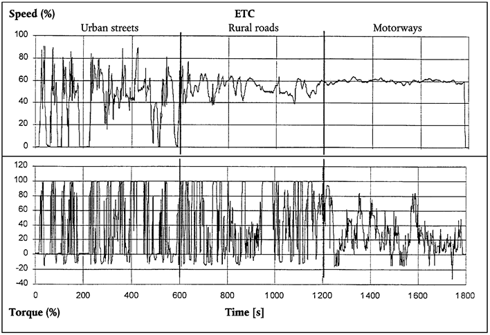
Appendix 4MEASUREMENT AND SAMPLING PROCEDURES
[F11. INTRODUCTION U.K.
Gaseous components, particulates, and smoke emitted by the engine submitted for testing shall be measured by the methods described in Annex V. The respective sections of Annex V describe the recommended analytical systems for the gaseous emissions (section 1), the recommended particulate dilution and sampling systems (section 2), and the recommended opacimeters for smoke measurement (section 3).
For the ESC, the gaseous components shall be determined in the raw exhaust gas. Optionally, they may be determined in the diluted exhaust gas, if a full flow dilution system is used for particulate determination. Particulates shall be determined with either a partial flow or a full flow dilution system.
For the ETC, the following systems may be used
a CVS full flow dilution system for determining gaseous and particulate emissions (double dilution systems are permissible),
or
a combination of raw exhaust measurement for the gaseous emissions and a partial flow dilution system for particulate emissions,
or
any combination of the two principles (e.g. raw gaseous measurement and full flow particulate measurement).]
2.DYNAMOMETER AND TEST CELL EQUIPMENTU.K.
The following equipment shall be used for emission tests of engines on engine dynamometers.
2.1.Engine dynamometerU.K.
An engine dynamometer shall be used with adequate characteristics to perform the test cycles described in Appendices 1 and 2 to this Annex. The speed measuring system shall have an accuracy of ± 2 % of reading. The torque measuring system shall have an accuracy of ± 3 % of reading in the range > 20 % of full scale, and an accuracy of ± 0,6 % of full scale in the range ≤ 20 % of full scale.
[F12.2. Other instruments U.K.
Measuring instruments for fuel consumption, air consumption, temperature of coolant and lubricant, exhaust gas pressure and intake manifold depression, exhaust gas temperature, air intake temperature, atmospheric pressure, humidity and fuel temperature shall be used, as required. These instruments shall satisfy the requirements given in table 9:
Table 9
Accuracy of measuring instruments
| Measuring Instrument | Accuracy |
|---|---|
| Fuel Consumption | ±2 % of Engine's Maximum Value |
| Air Consumption | ±2 % of reading or ±1 % of engine's maximum value whichever is greater |
| Exhaust Gas Flow | ±2, % of reading or ±1,5 % of engine's maximum value whichever is greater |
| Temperatures ≤ 600 K (327 °C) | ±2 K Absolute |
| Temperatures ≥ 600 K (327 °C) | ±1 % of Reading |
| Atmospheric Pressure | ± 0,1 kPa Absolute |
| Exhaust Gas Pressure | ± 0,2 kPa Absolute |
| Intake Depression | ± 0,05 kPa Absolute |
| Other Pressures | ± 0,1 kPa Absolute |
| Relative Humidity | ±3 % Absolute |
| Absolute Humidity | ±5 % of Reading |
| Dilution Air Flow | ±2 % of Reading |
| Diluted Exhaust Gas Flow | ±2 % of Reading] |
F32.3.Exhaust gas flowU.K.
. . . . . . . . . . . . . . . . . . . . . . . . . . . . . . . .
Textual Amendments
F3 Deleted by Commission Directive 2005/78/EC of 14 November 2005 implementing Directive 2005/55/EC of the European Parliament and of the Council on the approximation of the laws of the Member States relating to the measures to be taken against the emission of gaseous and particulate pollutants from compression-ignition engines for use in vehicles, and the emission of gaseous pollutants from positive ignition engines fuelled with natural gas or liquefied petroleum gas for use in vehicles and amending Annexes I, II, III, IV and VI thereto (Text with EEA relevance).
F32.4.Diluted exhaust gas flowU.K.
. . . . . . . . . . . . . . . . . . . . . . . . . . . . . . . .
[F13. DETERMINATION OF THE GASEOUS COMPONENTS U.K.
3.1. General analyser specifications U.K.
The analysers shall have a measuring range appropriate for the accuracy required to measure the concentrations of the exhaust gas components (section 3.1.1). It is recommended that the analysers be operated such that the measured concentration falls between 15 % and 100 % of full scale.
If read-out systems (computers, data loggers) can provide sufficient accuracy and resolution below 15 % of full scale, measurements below 15 % of full scale are also acceptable. In this case, additional calibrations of at least 4 non-zero nominally equally spaced points are to be made to ensure the accuracy of the calibration curves according to section 1.6.4 of Appendix 5 to this Annex.
The electromagnetic compatibility (EMC) of the equipment shall be on a level as to minimise additional errors.
3.1.1. Accuracy U.K.
The analyser shall not deviate from the nominal calibration point by more than ±2 % of the reading over the whole measurement range except zero, or ± 0,3 % of full scale whichever is larger. The accuracy shall be determined according to the calibration requirements laid down in section 1.6 of Appendix 5 to this Annex.
Note: For the purpose of this Directive, accuracy is defined as the deviation of the analyser reading from the nominal calibration values using a calibration gas (= true value). U.K.
3.1.2. Precision U.K.
The precision, defined as 2,5 times the standard deviation of 10 repetitive responses to a given calibration or span gas, has to be not greater than ±1 % of full scale concentration for each range used above 155 ppm (or ppmC) or ±2 % of each range used below 155 ppm (or ppmC).
3.1.3. Noise U.K.
The analyser peak-to-peak response to zero and calibration or span gases over any 10 second period shall not exceed 2 % of full scale on all ranges used.
3.1.4. Zero drift U.K.
Zero response is defined as the mean response, including noise, to a zero gas during a 30 seconds time interval. The drift of the zero response during a one hour period shall be less than 2 % of full scale on the lowest range used.
3.1.5. Span drift U.K.
Span response is defined as the mean response, including noise, to a span gas during a 30 seconds time interval. The drift of the span response during a one hour period shall be less than 2 % of full scale on the lowest range used.
3.1.6. Rise time U.K.
The rise time of the analyser installed in the measurement system shall not exceed 3,5 s.
Note: Only evaluating the response time of the analyser alone will not clearly define the suitability of the total system for transient testing. Volumes and especially dead volumes through out the system will not only effect the transportation time from the probe to the analyser, but also effect the rise time. Also transport times inside of an analyser would be defined as analyser response time, like the converter or water traps inside NO x analysers. The determination of the total system response time is described in section 1.5 of Appendix 5 to this Annex. U.K.
3.2. Gas drying U.K.
The optional gas drying device must have a minimal effect on the concentration of the measured gases. Chemical dryers are not an acceptable method of removing water from the sample.
3.3. Analysers U.K.
Sections 3.3.1 to 3.3.4 describe the measurement principles to be used. A detailed description of the measurement systems is given in Annex V. The gases to be measured shall be analysed with the following instruments. For non-linear analysers, the use of linearising circuits is permitted.
3.3.1. Carbon monoxide (CO) analysis U.K.
The carbon monoxide analyser shall be of the Non-Dispersive InfraRed (NDIR) absorption type.
3.3.2. Carbon dioxide (CO 2 ) analysis U.K.
The carbon dioxide analyser shall be of the Non-Dispersive InfraRed (NDIR) absorption type.
3.3.3. Hydrocarbon (HC) analysis U.K.
For diesel and LPG fuelled gas engines, the hydrocarbon analyser shall be of the Heated Flame Ionisation Detector (HFID) type with detector, valves, pipework, etc. heated so as to maintain a gas temperature of 463 K ±10 K (190 ±10 °C). For NG fuelled gas engines, the hydrocarbon analyser may be of the non heated Flame Ionisation Detector (FID) type depending upon the method used (see section 1.3 of Annex V).
3.3.4. Non-Methane Hydrocarbon (NMHC) analysis (NG fuelled gas engines only) U.K.
Non-methane hydrocarbons shall be determined by either of the following methods:
3.3.4.1. Gas chromatographic (GC) method U.K.
Non-methane hydrocarbons shall be determined by subtraction of the methane analysed with a Gas Chromatograph (GC) conditioned at 423 K (150 °C) from the hydrocarbons measured according to section 3.3.3.
3.3.4.2. Non-Methane Cutter (NMC) method U.K.
The determination of the non-methane fraction shall be performed with a heated NMC operated in line with an FID as per section 3.3.3 by subtraction of the methane from the hydrocarbons.
3.3.5. Oxides of Nitrogen (NO x ) analysis U.K.
The oxides of nitrogen analyser shall be of the ChemiLuminescent Detector (CLD) or Heated ChemiLuminescent Detector (HCLD) type with a NO 2 /NO converter, if measured on a dry basis. If measured on a wet basis, a HCLD with converter maintained above 328 K (55 °C) shall be used, provided the water quench check (see section 1.9.2.2 of Appendix 5 to this Annex) is satisfied.
3.3.6. Air-to-fuel measurement U.K.
The air to fuel measurement equipment used to determine the exhaust gas flow as specified in section 4.2.5 of Appendix 2 to this Annex shall be a wide range air to fuel ratio sensor or lambda sensor of Zirconia type. The sensor shall be mounted directly on the exhaust pipe where the exhaust gas temperature is high enough to eliminate water condensation.
The accuracy of the sensor with incorporated electronics shall be within:
±3 % of reading
λ < 2
±5 % of reading
2 ≤ λ < 5
±10 % of reading
5 ≤ λ
To fulfil the accuracy specified above, the sensor shall be calibrated as specified by the instrument manufacturer.
3.4. Sampling of Gaseous Emissions U.K.
3.4.1. Raw exhaust gas U.K.
The gaseous emissions sampling probes shall be fitted at least 0,5 m or 3 times the diameter of the exhaust pipe — whichever is the larger — upstream of the exit of the exhaust gas system but sufficiently close to the engine as to ensure an exhaust gas temperature of at least 343 K (70 °C) at the probe.
In the case of a multi-cylinder engine with a branched exhaust manifold, the inlet of the probe shall be located sufficiently far downstream so as to ensure that the sample is representative of the average exhaust emissions from all cylinders. In multi-cylinder engines having distinct groups of manifolds, such as in a ‘Vee’ engine configuration, it is recommended to combine the manifolds upstream of the sampling probe. If this is not practical, it is permissible to acquire a sample from the group with the highest CO 2 emission. Other methods which have been shown to correlate with the above methods may be used. For exhaust emission calculation the total exhaust mass flow shall be used.
If the engine is equipped with an exhaust aftertreatment system, the exhaust sample shall be taken downstream of the exhaust aftertreatment system.
3.4.2. Diluted exhaust gas U.K.
The exhaust pipe between the engine and the full flow dilution system shall conform to the requirements of section 2.3.1 of Annex V (EP).
The gaseous emissions sample probe(s) shall be installed in the dilution tunnel at a point where the dilution air and exhaust gas are well mixed, and in close proximity to the particulates sampling probe.
Sampling can generally be done in two ways:
the pollutants are sampled into a sampling bag over the cycle and measured after completion of the test,
the pollutants are sampled continuously and integrated over the cycle; this method is mandatory for HC and NO x .
4. DETERMINATION OF THE PARTICULATES U.K.
The determination of the particulates requires a dilution system. Dilution may be accomplished by a partial flow dilution system or a full flow double dilution system. The flow capacity of the dilution system shall be large enough to completely eliminate water condensation in the dilution and sampling systems. The temperature of the diluted exhaust gas shall be below 325 K (52 °C) (24) immediately upstream of the filter holders. Humidity control of the dilution air before entering the dilution system is permitted, and especially dehumidifying is useful if dilution air humidity is high. The temperature of the dilution air shall be higher than 288 K (15 °C) in close proximity to the entrance into the dilution tunnel.
The partial flow dilution system has to be designed to extract a proportional raw exhaust sample from the engine exhaust stream, thus responding to excursions in the exhaust stream flow rate, and introduce dilution air to this sample to achieve a temperature below 325 K (52 °C) at the test filter. For this it is essential that the dilution ratio or the sampling ratio r dil or r s be determined such that the accuracy limits of section 3.2.1 of Appendix 5 to this Annex are fulfilled. Different extraction methods can be applied, whereby the type of extraction used dictates to a significant degree the sampling hardware and procedures to be used (section 2.2 of Annex V).
In general, the particulate sampling probe shall be installed in close proximity to the gaseous emissions sampling probe, but sufficiently distant as to not cause interference. Therefore, the installation provisions of section 3.4.1 also apply to particulate sampling. The sampling line shall conform to the requirements of section 2 of Annex V.
In the case of a multi-cylinder engine with a branched exhaust manifold, the inlet of the probe shall be located sufficiently far downstream so as to ensure that the sample is representative of the average exhaust emissions from all cylinders. In multi-cylinder engines having distinct groups of manifolds, such as in a ‘ Vee ’ engine configuration, it is recommended to combine the manifolds upstream of the sampling probe. If this is not practical, it is permissible to acquire a sample from the group with the highest particulate emission. Other methods which have been shown to correlate with the above methods may be used. For exhaust emission calculation the total exhaust mass flow shall be used.
To determine the mass of the particulates, a particulate sampling system, particulate sampling filters, a microgram balance, and a temperature and humidity controlled weighing chamber, are required.
For particulate sampling, the single filter method shall be applied which uses one filter (see section 4.1.3) for the whole test cycle. For the ESC, considerable attention must be paid to sampling times and flows during the sampling phase of the test.
4.1. Particulate sampling filters U.K.
The diluted exhaust shall be sampled by a filter that meets the requirements of sections 4.1.1 and 4.1.2 during the test sequence.
4.1.1. Filter specification U.K.
Fluorocarbon coated glass fiber filters are required. All filter types shall have a 0,3 μm DOP (di-octylphthalate) collection efficiency of at least 99 % at a gas face velocity between 35 and 100 cm/s.
4.1.2. Filter size U.K.
Particulate filters with a diameter of 47 mm or 70 mm are recommended. Larger diameter filters are acceptable (section 4.1.4), but smaller diameter filters are not permitted.
4.1.3. Filter face velocity U.K.
A gas face velocity through the filter of 35 to 100 cm/s shall be achieved. The pressure drop increase between the beginning and the end of the test shall be no more than 25 kPa.
4.1.4. Filter loading U.K.
The required minimum filter loadings for the most common filter sizes are shown in table 10. For larger filter sizes, the minimum filter loading shall be 0,065 mg/ 1 000 mm 2 filter area.
Table 10
Minimum Filter Loadings
| Filter Diameter (mm) | Minimum loading (mg) |
|---|---|
| 47 | 0,11 |
| 70 | 0,25 |
| 90 | 0,41 |
| 110 | 0,62 |
If, based on previous testing, the required minimum filter loading is unlikely to be reached on a test cycle after optimisation of flow rates and dilution ratio, a lower filter loading may be acceptable, with the agreement of the parties involved, if it can be shown to meet the accuracy requirements of section 4.2, e.g. with a 0,1 μg balance.
4.1.5. Filter holder U.K.
For the emissions test, the filters shall be placed in a filter holder assembly meeting the requirements of section 2.2 of Annex V. The filter holder assembly shall be of a design that provides an even flow distribution across the filter stain area. Quick acting valves shall be located either upstream or downstream of the filter holder. An inertial pre-classifier with a 50 % cut point between 2,5 μm and 10 μm may be installed immediately upstream of the filter holder. The use of the pre-classifier is strongly recommended if an open tube sampling probe facing upstream into the exhaust flow is used.
4.2. Weighing chamber and analytical balance specifications U.K.
4.2.1. Weighing chamber conditions U.K.
The temperature of the chamber (or room) in which the particulate filters are conditioned and weighed shall be maintained to within 295 K ±3 K (22 °C ±3 °C) during all filter conditioning and weighing. The humidity shall be maintained to a dewpoint of 282,5 K ±3 K (9,5 °C ±3 °C) and a relative humidity of 45 % ±8 %.
4.2.2. Reference filter weighing U.K.
The chamber (or room) environment shall be free of any ambient contaminants (such as dust) that would settle on the particulate filters during their stabilisation. Disturbances to weighing room specifications as outlined in section 4.2.1 will be allowed if the duration of the disturbances does not exceed 30 minutes. The weighing room should meet the required specifications prior to personal entrance into the weighing room. At least two unused reference filters shall be weighed within 4 hours of, but preferably at the same time as the sample filter weightings. They shall be the same size and material as the sample filters.
If the average weight of the reference filters changes between sample filter weightings by more than 10 μg, then all sample filters shall be discarded and the emissions test repeated.
If the weighing room stability criteria outlined in section 4.2.1 is not met, but the reference filter weightings meet the above criteria, the engine manufacturer has the option of accepting the sample filter weights or voiding the tests, fixing the weighing room control system and re-running the test.
4.2.3. Analytical balance U.K.
The analytical balance used to determine the filter weight shall have a precision (standard deviation) of at least 2 μg and a resolution of at least 1 μg (1 digit = 1 μg) specified by the balance manufacturer.
4.2.4. Elimination of static electricity effects U.K.
To eliminate the effects of static electricity, the filters shall be neutralized prior to weighing, e.g. by a Polonium neutralizer, a Faraday cage or a device of similar effect.
4.2.5. Specifications for flow measurement U.K.
4.2.5.1. General requirements U.K.
Absolute accuracies of flow meter or flow measurement instrumentation shall be as specified in section 2.2.
4.2.5.2. Special provisions for partial flow dilution systems U.K.
For partial flow dilution systems, the accuracy of the sample flow q mp is of special concern, if not measured directly, but determined by differential flow measurement:
q mp = q mdew – q mdw
In this case an accuracy of ±2 % for q mdew and q mdw is not sufficient to guarantee acceptable accuracies of q mp . If the gas flow is determined by differential flow measurement, the maximum error of the difference shall be such that the accuracy of q mp is within ±5 % when the dilution ratio is less than 15. It can be calculated by taking root-mean-square of the errors of each instrument.
Acceptable accuracies of q mp can be obtained by either of the following methods:
The absolute accuracies of q mdew and q mdw are ±0,2 % which guarantees an accuracy of q mp of ≤ 5 % at a dilution ratio of 15. However, greater errors will occur at higher dilution ratios;
calibration of q mdw relative to q mdew is carried out such that the same accuracies for q mp as in a) are obtained. For the details of such a calibration see section 3.2.1 of Appendix 5 to Annex III;
the accuracy of q mp is determined indirectly from the accuracy of the dilution ratio as determined by a tracer gas, e.g. CO 2 . Again, accuracies equivalent to method a) for q mp are required;
the absolute accuracy of q mdew and q mdw is within ±2 % of full scale, the maximum error of the difference between q mdew and q mdw is within 0,2 %, and the linearity error is within ±0,2 % of the highest q mdew observed during the test.]
5.DETERMINATION OF SMOKEU.K.
This section provides specifications for the required and optional test equipment to be used for the ELR test. The smoke shall be measured with an opacimeter having an opacity and a light absorption coefficient readout mode. The opacity readout mode shall only be used for calibration and checking of the opacimeter. The smoke values of the test cycle shall be measured in the light absorption coefficient readout mode.
5.1.General requirementsU.K.
The ELR requires the use of a smoke measurement and data processing system which includes three functional units. These units may be integrated into a single component or provided as a system of interconnected components. The three functional units are:
an opacimeter meeting the specifications of Annex V, Section 3,
a data processing unit capable of performing the functions described in Annex III, Appendix 1, Section 6,
a printer and/or electronic storage medium to record and output the required smoke values specified in Annex III, Appendix 1, Section 6.3.
5.2.Specific requirementsU.K.
5.2.1.LinearityU.K.
The linearity shall be within ± 2 % opacity.
5.2.2.Zero driftU.K.
The zero drift during a one hour period shall not exceed ± 1 % opacity.
5.2.3.Opacimeter display and rangeU.K.
For display in opacity, the range shall be 0-100 % opacity, and the readability 0,1 % opacity. For display in light absorption coefficient, the range shall be 0-30 m-1 light absorption coefficient, and the readability 0,01 m-1 light absorption coefficient.
5.2.4.Instrument response timeU.K.
The physical response time of the opacimeter shall not exceed 0,2 s. The physical response time is the difference between the times when the output of a rapid response receiver reaches 10 and 90 % of the full deviation when the opacity of the gas being measured is changed in less than 0,1 s.
The electrical response time of the opacimeter shall not exceed 0,05 s. The electrical response time is the difference between the times when the opacimeter output reaches 10 and 90 % of the full scale when the light source is interrupted or completely extinguished in less than 0,01 s.
5.2.5.Neutral density filtersU.K.
Any neutral density filter used in conjunction with opacimeter calibration, linearity measurements, or setting span shall have its value known to within 1,0 % opacity. The filter's nominal value must be checked for accuracy at least yearly using a reference traceable to a national or international standard.
Neutral density filters are precision devices and can easily be damaged during use. Handling should be minimised and, when required, should be done with care to avoid scratching or soiling of the filter.
Appendix 5CALIBRATION PROCEDURE
1.CALIBRATION OF THE ANALYTICAL INSTRUMENTSU.K.
1.1.IntroductionU.K.
Each analyser shall be calibrated as often as necessary to fulfil the accuracy requirements of this Directive. The calibration method that shall be used is described in this section for the analysers indicated in Annex III, Appendix 4, Section 3 and Annex V, Section 1.
1.2.Calibration gasesU.K.
The shelf life of all calibration gases must be respected.
The expiration date of the calibration gases stated by the manufacturer shall be recorded.
1.2.1.Pure gasesU.K.
The required purity of the gases is defined by the contamination limits given below. The following gases must be available for operation:
Purified nitrogen
(Contamination ≤ 1 ppm C1, ≤ 1 ppm CO, ≤ 400 ppm CO2, ≤ 0,1 ppm NO)
Purified oxygen
(Purity > 99,5 % vol O2)
Hydrogen-helium mixture
(40 ± 2 % hydrogen, balance helium)
(Contamination ≤ 1 ppm C1, ≤ 400 ppm CO2)
Purified synthetic air
(Contamination ≤ 1 ppm C1, ≤ 1 ppm CO, ≤ 400 ppm CO2, ≤ 0,1 ppm NO)
(Oxygen content between 18-21 % vol.)
Purified propane or CO for the CVS verification
1.2.2.Calibration and span gasesU.K.
Mixtures of gases having the following chemical compositions shall be available:
C3H8 and purified synthetic air (see Section 1.2.1);
CO and purified nitrogen;
NOx and purified nitrogen (the amount of NO2 contained in this calibration gas must not exceed 5 % of the NO content);
CO2 and purified nitrogen;
CH4 and purified synthetic air;
C2H6 and purified synthetic air.
Note: Other gas combinations are allowed provided the gases do not react with one another.U.K.
The true concentration of a calibration and span gas must be within ± 2 % of the nominal value. All concentrations of calibration gas shall be given on a volume basis (volume percent or volume ppm).
The gases used for calibration and span may also be obtained by means of a gas divider, diluting with purified N2 or with purified synthetic air. The accuracy of the mixing device must be such that the concentration of the diluted calibration gases may be determined to within ± 2 %.
[F21.2.3. Use of precision blending devices U.K.
The gases used for calibration and span may also be obtained by means of precision blending devices (gas dividers), diluting with purified N 2 or with purified synthetic air. The accuracy of the mixing device must be such that the concentration of the blended calibration gases is accurate to within ±2 %. This accuracy implies that primary gases used for blending must be known to an accuracy of at least ±1 %, traceable to national or international gas standards. The verification shall be performed at between 15 and 50 % of full scale for each calibration incorporating a blending device.
Optionally, the blending device may be checked with an instrument which by nature is linear, e.g. using NO gas with a CLD. The span value of the instrument shall be adjusted with the span gas directly connected to the instrument. The blending device shall be checked at the used settings and the nominal value shall be compared to the measured concentration of the instrument. This difference shall in each point be within ±1 % of the nominal value.]
1.3.Operating procedure for analysers and sampling systemU.K.
The operating procedure for analysers shall follow the start-up and operating instructions of the instrument manufacturer. The minimum requirements given in Sections 1.4 to 1.9 shall be included.
[F11.4. Leakage test U.K.
A system leakage test shall be performed. The probe shall be disconnected from the exhaust system and the end plugged. The analyser pump shall be switched on. After an initial stabilisation period all flow meters should read zero. If not, the sampling lines shall be checked and the fault corrected.
The maximum allowable leakage rate on the vacuum side shall be 0,5 % of the in-use flow rate for the portion of the system being checked. The analyser flows and bypass flows may be used to estimate the in-use flow rates.
Alternatively, the system may be evacuated to a pressure of at least 20 kPa vacuum (80 kPa absolute). After an initial stabilisation period the pressure increase Δp (kPa/min) in the system should not exceed:
Δp = p / V s × 0,005 × q v s
where:
V s
=
system volume, l
q v s
=
system flow rate, l/min
Another method is the introduction of a concentration step change at the beginning of the sampling line by switching from zero to span gas. If after an adequate period of time the reading is about 1 % low compared to the introduced concentration, these points to calibration or leakage problems.]
[F21.5. Response time check of analytical system U.K.
The system settings for the response time evaluation shall be exactly the same as during measurement of the test run (i.e. pressure, flow rates, filter settings on the analyzers and all other response time influences). The response time determination shall be done with gas switching directly at the inlet of the sample probe. The gas switching shall be done in less than 0,1 second. The gases used for the test shall cause a concentration change of at least 60 % FS.
The concentration trace of each single gas component shall be recorded. The response time is defined to be the difference in time between the gas switching and the appropriate change of the recorded concentration. The system response time ( t 90 ) consists of the delay time to the measuring detector and the rise time of the detector. The delay time is defined as the time from the change ( t 0 ) until the response is 10 % of the final reading ( t 10 ). The rise time is defined as the time between 10 % and 90 % response of the final reading ( t 90 – t 10 ).
For time alignment of the analyzer and exhaust flow signals in the case of raw measurement, the transformation time is defined as the time from the change ( t 0 ) until the response is 50 % of the final reading ( t 50 ).
The system response time shall be ≤ 10 seconds with a rise time ≤ 3,5 seconds for all limited components (CO, NO x , HC or NMHC) and all ranges used.]
[F11.6. Calibration U.K.
1.6.1. Instrument assembly U.K.
The instrument assembly shall be calibrated and calibration curves checked against standard gases. The same gas flow rates shall be used as when sampling exhaust.
1.6.2. Warming-up time U.K.
The warming-up time should be according to the recommendations of the manufacturer. If not specified, a minimum of two hours is recommended for warming up the analysers.
1.6.3. NDIR and HFID analyser U.K.
The NDIR analyser shall be tuned, as necessary, and the combustion flame of the HFID analyser shall be optimised (section 1.8.1).
1.6.4. Establishment of the calibration curve U.K.
Each normally used operating range shall be calibrated
Using purified synthetic air (or nitrogen), the CO, CO 2 , NO x and HC analysers shall be set at zero
The appropriate calibration gases shall be introduced to the analysers, the values recorded, and the calibration curve established
The calibration curve shall be established by at least 6 calibration points (excluding zero) approximately equally spaced over the operating range. The highest nominal concentration shall be equal to or higher than 90 % of full scale
The calibration curve shall be calculated by the method of least-squares. A best-fit linear or non-linear equation may be used
The calibration points shall not differ from the least-squares best-fit line by more than ±2 % of reading or ±0,3 % of full scale whichever is larger
The zero setting shall be rechecked and the calibration procedure repeated, if necessary.
1.6.5. Alternative methods U.K.
If it can be shown that alternative technology (e.g. computer, electronically controlled range switch, etc.) can give equivalent accuracy, then these alternatives may be used.
1.6.6. Calibration of tracer gas analyser for exhaust flow measurement U.K.
The calibration curve shall be established by at least 6 calibration points (excluding zero) approximately equally spaced over the operating range. The highest nominal concentration shall be equal to or higher than 90 % of full scale. The calibration curve is calculated by the method of least squares.
The calibration points shall not differ from the least-squares best-fit line by more than ±2 % of reading or ±0,3 % of full scale whichever is larger.
The analyser shall be set at zero and spanned prior to the test run using a zero gas and a span gas whose nominal value is more than 80 % of the analyser full scale.]
[F11.6.7.] Verification of the calibrationU.K.
Each normally used operating range shall be checked prior to each analysis in accordance with the following procedure.
The calibration shall be checked by using a zero gas and a span gas whose nominal value is more than 80 % of full scale of the measuring range.
If, for the two points considered, the value found does not differ by more than ± 4 % of full scale from the declared reference value, the adjustment parameters may be modified. Should this not be the case, a new calibration curve shall be established in accordance with Section 1.5.5.
1.7.Efficiency test of the NOx converterU.K.
The efficiency of the converter used for the conversion of NO2 into NO shall be tested as given in Sections 1.7.1 to 1.7.8 (Figure 6).
1.7.1.Test set-upU.K.
Using the test set-up as shown in Figure 6 (see also Annex III, Appendix 4, Section 3.3.5) and the procedure below, the efficiency of converters can be tested by means of an ozonator.
1.7.2.CalibrationU.K.
The CLD and the HCLD shall be calibrated in the most common operating range following the manufacturer's specifications using zero and span gas (the NO content of which must amount to about 80 % of the operating range and the NO2 concentration of the gas mixture to less than 5 % of the NO concentration). The NOx analyser must be in the NO mode so that the span gas does not pass through the converter. The indicated concentration has to be recorded.
1.7.3.CalculationU.K.
The efficiency of the NOx converter is calculated as follows:
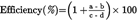
where,
a
=
is the NOx concentration according to Section 1.7.6
b
=
is the NOx concentration according to Section 1.7.7
c
=
is the NO concentration according to Section 1.7.4
d
=
is the NO concentration according to Section 1.7.5
1.7.4.Adding of oxygenU.K.
Via a T-fitting, oxygen or zero air is added continuously to the gas flow until the concentration indicated is about 20 % less than the indicated calibration concentration given in Section 1.7.2. (The analyser is in the NO mode). The indicated concentration c shall be recorded. The ozonator is kept deactivated throughout the process.
1.7.5.Activation of the ozonatorU.K.
The ozonator is now activated to generate enough ozone to bring the NO concentration down to about 20 % (minimum 10 %) of the calibration concentration given in Section 1.7.2. The indicated concentration d shall be recorded. (The analyser is in the NO mode).
1.7.6.NOx modeU.K.
The NO analyser is then switched to the NOx mode so that the gas mixture (consisting of NO, NO2, O2 and N2) now passes through the converter. The indicated concentration a shall be recorded. (The analyser is in the NOx mode).
1.7.7.Deactivation of the ozonatorU.K.
The ozonator is now deactivated. The mixture of gases described in Section 1.7.6 passes through the converter into the detector. The indicated concentration b shall be recorded. (The analyser is in the NOx mode).
1.7.8.NO modeU.K.
Switched to NO mode with the ozonator deactivated, the flow of oxygen or synthetic air is also shut off. The NOx reading of the analyser shall not deviate by more than ± 5 % from the value measured according to Section 1.7.2. (The analyser is in the NO mode).
1.7.9.Test intervalU.K.
The efficiency of the converter must be tested prior to each calibration of the NOx analyser.
1.7.10.Efficiency requirementU.K.
The efficiency of the converter shall not be less than 90 %, but a higher efficiency of 95 % is strongly recommended.
Note:U.K.
If, with the analyser in the most common range, the ozonator cannot give a reduction from 80 % to 20 % according to Section 1.7.5, then the highest range which will give the reduction shall be used.U.K.

1.8.Adjustment of the FIDU.K.
1.8.1.Optimisation of the detector responseU.K.
The FID must be adjusted as specified by the instrument manufacturer. A propane in air span gas should be used to optimise the response on the most common operating range.
With the fuel and air flow rates set at the manufacturer's recommendations, a 350 ± 75 ppm C span gas shall be introduced to the analyser. The response at a given fuel flow shall be determined from the difference between the span gas response and the zero gas response. The fuel flow shall be incrementally adjusted above and below the manufacturer's specification. The span and zero response at these fuel flows shall be recorded. The difference between the span and zero response shall be plotted and the fuel flow adjusted to the rich side of the curve.
1.8.2.Hydrocarbon response factorsU.K.
The analyser shall be calibrated using propane in air and purified synthetic air, according to Section 1.5.
Response factors shall be determined when introducing an analyser into service and after major service intervals. The response factor (Rf) for a particular hydrocarbon species is the ratio of the FID C1 reading to the gas concentration in the cylinder expressed by ppm C1.
The concentration of the test gas must be at a level to give a response of approximately 80 % of full scale. The concentration must be known to an accuracy of ± 2 % in reference to a gravimetric standard expressed in volume. In addition, the gas cylinder must be preconditioned for 24 hours at a temperature of 298 K ± 5 K (25 °C ± 5 °C).
The test gases to be used and the recommended relative response factor ranges are as follows:
methane and purified synthetic air 1,00 ≤ Rf ≤ 1,15
propylene and purified synthetic air 0,90 ≤ Rf ≤ 1,10
toluene and purified synthetic air 0,90 ≤ Rf ≤ 1,10
These values are relative to the response factor (Rf) of 1,00 for propane and purified synthetic air.
1.8.3.Oxygen interference checkU.K.
The oxygen interference check shall be determined when introducing an analyser into service and after major service intervals.
The response factor is defined and shall be determined as described in Section 1.8.2. The test gas to be used and the recommended relative response factor range are as follows:
propane and nitrogen 0,95 ≤ Rf ≤ 1,05
This value is relative to the response factor (Rf) of 1,00 for propane and purified synthetic air.
The FID burner air oxygen concentration must be within ± 1 mole % of the oxygen concentration of the burner air used in the latest oxygen interference check. If the difference is greater, the oxygen interference must be checked and the analyser adjusted, if necessary.
1.8.4.Efficiency of the non-methane cutter (NMC, for NG fuelled gas engines only)U.K.
The NMC is used for the removal of the non-methane hydrocarbons from the sample gas by oxidising all hydrocarbons except methane. Ideally, the conversion for methane is 0 %, and for the other hydrocarbons represented by ethane is 100 %. For the accurate measurement of NMHC, the two efficiencies shall be determined and used for the calculation of the NMHC emission mass flow rate (see Annex III, Appendix 2, Section 4.3).
1.8.4.1.Methane efficiencyU.K.
Methane calibration gas shall be flown through the FID with and without bypassing the NMC and the two concentrations recorded. The efficiency shall be determined as follows:

where,
concw
=
HC concentration with CH4 flowing through the NMC
concw/o
=
HC concentration with CH4 bypassing the NMC
1.8.4.2.Ethane efficiencyU.K.
Ethane calibration gas shall be flown through the FID with and without bypassing the NMC and the two concentrations recorded. The efficiency shall be determined as follows

where,
concw
=
HC concentration with C2H6 flowing through the NMC
concw/o
=
HC concentration with C2H6 bypassing the NMC
1.9.Interference effects with CO, CO2, and NOx analysersU.K.
Gases present in the exhaust other than the one being analysed can interfere with the reading in several ways. Positive interference occurs in NDIR instruments where the interfering gas gives the same effect as the gas being measured, but to a lesser degree. Negative interference occurs in NDIR instruments by the interfering gas broadening the absorption band of the measured gas, and in CLD instruments by the interfering gas quenching the radiation. The interference checks in Sections 1.9.1 and 1.9.2 shall be performed prior to an analyser's initial use and after major service intervals.
1.9.1.CO analyser interference checkU.K.
Water and CO2 can interfere with the CO analyser performance. Therefore, a CO2 span gas having a concentration of 80 to 100 % of full scale of the maximum operating range used during testing shall be bubbled through water at room temperature and the analyser response recorded. The analyser response must not be more than 1 % of full scale for ranges equal to or above 300 ppm or more than 3 ppm for ranges below 300 ppm.
1.9.2.NOx analyser quench checksU.K.
The two gases of concern for CLD (and HCLD) analysers are CO2 and water vapour. Quench responses to these gases are proportional to their concentrations, and therefore require test techniques to determine the quench at the highest expected concentrations experienced during testing.
1.9.2.1.CO2 quench checkU.K.
A CO2 span gas having a concentration of 80 to 100 % of full scale of the maximum operating range shall be passed through the NDIR analyser and the CO2 value recorded as A. It shall then be diluted approximately 50 % with NO span gas and passed through the NDIR and (H)CLD, with the CO2 and NO values recorded as B and C, respectively. The CO2 shall then be shut off and only the NO span gas be passed through the (H)CLD and the NO value recorded as D.
The quench, which must not be greater than 3 % of full scale, shall be calculated as follows:

where,
A
=
is the undiluted CO2 concentration measured with NDIR in %
B
=
is the diluted CO2 concentration measured with NDIR in %
C
=
is the diluted NO concentration measured with (H)CLD in ppm
D
=
is the undiluted NO concentration measured with (H)CLD in ppm
Alternative methods of diluting and quantifying of CO2 and NO span gas values such as dynamic mixing/blending can be used.
1.9.2.2.Water quench checkU.K.
This check applies to wet gas concentration measurements only. Calculation of water quench must consider dilution of the NO span gas with water vapour and scaling of water vapour concentration of the mixture to that expected during testing.
A NO span gas having a concentration of 80 to 100 % of full scale of the normal operating range shall be passed through the (H)CLD and the NO value recorded as D. The NO span gas shall then be bubbled through water at room temperature and passed through the (H)CLD and the NO value recorded as C. The analyser's absolute operating pressure and the water temperature shall be determined and recorded as E and F, respectively. The mixture's saturation vapour pressure that corresponds to the bubbler water temperature F shall be determined and recorded as G. The water vapour concentration (H, in %) of the mixture shall be calculated as follows:

The expected diluted NO span gas (in water vapour) concentration (De) shall be calculated as follows:

For diesel exhaust, the maximum exhaust water vapour concentration (Hm, in %) expected during testing shall be estimated, under the assumption of a fuel atom H/C ratio of 1,8:1, from the undiluted CO2 span gas concentration (A, as measured in Section 1.9.2.1) as follows:

The water quench, which must not be greater than 3 %, shall be calculated as follows:

where,
De
=
is the expected diluted NO concentration in ppm
C
=
is the diluted NO concentration in ppm
Hm
=
is the maximum water vapour concentration in %
H
=
is the actual water vapour concentration in %
Note:U.K.
It is important that the NO span gas contains minimal NO2 concentration for this check, since absorption of NO2 in water has not been accounted for in the quench calculations.U.K.
1.10.Calibration intervalsU.K.
The analysers shall be calibrated according to Section 1.5 at least every three months or whenever a system repair or change is made that could influence calibration.
2.CALIBRATION OF THE CVS-SYSTEMU.K.
2.1.GeneralU.K.
The CVS system shall be calibrated by using an accurate flowmeter traceable to national or international standards and a restricting device. The flow through the system shall be measured at different restriction settings, and the control parameters of the system shall be measured and related to the flow.
Various types of flowmeters may be used, e.g. calibrated venturi, calibrated laminar flowmeter, calibrated turbinemeter.
2.2.Calibration of the Positive Displacement Pump (PDP)U.K.
All parameters related to the pump shall be simultaneously measured with the parameters related to the flowmeter which is connected in series with the pump. The calculated flow rate (in m3/min at pump inlet, absolute pressure and temperature) shall be plotted versus a correlation function which is the value of a specific combination of pump parameters. The linear equation which relates the pump flow and the correlation function shall then be determined. If a CVS has a multiple speed drive, the calibration shall be performed for each range used. Temperature stability shall be maintained during calibration.
2.2.1.Data analysisU.K.
The air flowrate (Qs) at each restriction setting (minimum six settings) shall be calculated in standard m3/min from the flowmeter data using the manufacturer's prescribed method. The air flow rate shall then be converted to pump flow (V0) in m3/rev at absolute pump inlet temperature and pressure as follows:

where,
Qs
=
air flow rate at standard conditions (101,3 kPa, 273 K), m3/s
T
=
temperature at pump inlet, K
pA
=
absolute pressure at pump inlet (pB-p1), kPa
n
=
pump speed, rev/s
To account for the interaction of pressure variations at the pump and the pump slip rate, the correlation function (X0) between pump speed, pressure differential from pump inlet to pump outlet and absolute pump outlet pressure shall be calculated as follows:

where,
Δpp
=
pressure differential from pump inlet to pump outlet, kPa
pA
=
absolute outlet pressure at pump outlet, kPa
A linear least-square fit shall be performed to generate the calibration equation as follows:

D0 and m are the intercept and slope constants, respectively, describing the regression lines.
For a CVS system with multiple speeds, the calibration curves generated for the different pump flow ranges shall be approximately parallel, and the intercept values (D0) shall increase as the pump flow range decreases.
The calculated values from the equation shall be within ± 0,5 % of the measured value of V0. Values of m will vary from one pump to another. Particulate influx over time will cause the pump slip to decrease, as reflected by lower values for m. Therefore, calibration shall be performed at pump start-up, after major maintenance, and if the total system verification (Section 2.4) indicates a change of the slip rate.
2.3.Calibration of the Critical Flow Venturi (CFV)U.K.
Calibration of the CFV is based upon the flow equation for a critical venturi. Gas flow is a function of inlet pressure and temperature, as shown below:

where,
Kv
=
calibration coefficient
pA
=
absolute pressure at venturi inlet, kPa
T
=
temperature at venturi inlet, K
2.3.1.Data analysisU.K.
The air flowrate (Qs) at each restriction setting (minimum eight settings) shall be calculated in standard m3/min from the flowmeter data using the manufacturer's prescribed method. The calibration coefficient shall be calculated from the calibration data for each setting as follows:

where,
Qs
=
air flow rate at standard conditions (101,3 kPa, 273 K), m3/s
T
=
temperature at the venturi inlet, K
pA
=
absolute pressure at venturi inlet, kPa
To determine the range of critical flow, Kv shall be plotted as a function of venturi inlet pressure. For critical (choked) flow, Kv will have a relatively constant value. As pressure decreases (vacuum increases), the venturi becomes unchoked and Kv decreases, which indicates that the CFV is operated outside the permissible range.
For a minimum of eight points in the region of critical flow, the average Kv and the standard deviation shall be calculated. The standard deviation shall not exceed ± 0,3 % of the average KV.
[F22.4. Calibration of the Subsonic Venturi (SSV) U.K.
Calibration of the SSV is based upon the flow equation for a subsonic venturi. Gas flow is a function of inlet pressure and temperature, pressure drop between the SSV inlet and throat.
2.4.1. Data analysis U.K.
The air flowrate (Q SSV ) at each restriction setting (minimum 16 settings) shall be calculated in standard m 3 /min from the flowmeter data using the manufacturer's prescribed method. The discharge coefficient shall be calculated from the calibration data for each setting as follows:

where:
Q SSV
=
air flow rate at standard conditions (101,3 kPa, 273 K), m 3 /s
T
=
temperature at the venturi inlet, K
d
=
diameter of the SSV throat, m


To determine the range of subsonic flow, C d shall be plotted as a function of Reynolds number at the SSV throat. The Re at the SSV throat is calculated with the following formula:
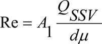
where:

Q SSV
=
air flow rate at standard conditions (101,3 kPa, 273 K), m 3 /s
d
=
diameter of the SSV throat, m
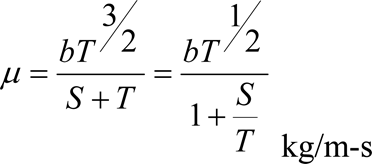

S
=
empirical constant = 110,4 K
Because Q SSV is an input to the Re formula, the calculations must be started with an initial guess for Q SSV or C d of the calibration venturi, and repeated until Q SSV converges. The convergence method must be accurate to 0,1 % of point or better.
For a minimum of sixteen points in the region of subsonic flow, the calculated values of C d from the resulting calibration curve fit equation must be within ±0,5 % of the measured C d for each calibration point.]
[F12.5.] Total system verificationU.K.
The total accuracy of the CVS sampling system and analytical system shall be determined by introducing a known mass of a pollutant gas into the system while it is being operated in the normal manner. The pollutant is analysed, and the mass calculated according to Annex III, Appendix 2, Section 4.3 except in the case of propane where a factor of 0,000472 is used in place of 0,000479 for HC. Either of the following two techniques shall be used.
[F12.5.1.] Metering with a critical flow orificeU.K.
A known quantity of pure gas (carbon monoxide or propane) shall be fed into the CVS system through a calibrated critical orifice. If the inlet pressure is high enough, the flow rate, which is adjusted by means of the critical flow orifice, is independent of the orifice outlet pressure (≡ critical flow). The CVS system shall be operated as in a normal exhaust emission test for about 5 to 10 minutes. A gas sample shall be analysed with the usual equipment (sampling bag or integrating method), and the mass of the gas calculated. The mass so determined shall be within ± 3 % of the known mass of the gas injected.
[F12.5.2.] Metering by means of a gravimetric techniqueU.K.
The weight of a small cylinder filled with carbon monoxide or propane shall be determined with a precision of ± 0,01 gram. For about 5 to 10 minutes, the CVS system shall be operated as in a normal exhaust emission test, while carbon monoxide or propane is injected into the system. The quantity of pure gas discharged shall be determined by means of differential weighing. A gas sample shall be analysed with the usual equipment (sampling bag or integrating method), and the mass of the gas calculated. The mass so determined shall be within ± 3 % of the known mass of the gas injected.
[F13. CALIBRATION OF THE PARTICULATE MEASURING SYSTEM U.K.
3.1. Introduction U.K.
The calibration of the particulate measurement is limited to the flow meters used to determine sample flow and dilution ratio. Each flow meter shall be calibrated as often as necessary to fulfil the accuracy requirements of this Directive. The calibration method that shall be used is described in section 3.2.
3.2. Flow measurement U.K.
3.2.1. Periodical calibration U.K.
To fulfil the absolute accuracy of the flow measurements as specified in section 2.2 of Appendix 4 to this Annex, the flow meter or the flow measurement instrumentation shall be calibrated with an accurate flow meter traceable to international and/or national standards.
If the sample gas flow is determined by differential flow measurement the flow meter or the flow measurement instrumentation shall be calibrated in one of the following procedures, such that the probe flow q mp into the tunnel shall fulfil the accuracy requirements of section 4.2.5.2 of Appendix 4 to this Annex:
(a)The flow meter for q mdw shall be connected in series to the flow meter for q mdew , the difference between the two flow meters shall be calibrated for at least 5 set points with flow values equally spaced between the lowest q mdw value used during the test and the value of q mdew used during the test. The dilution tunnel may be bypassed.
(b)A calibrated mass flow device shall be connected in series to the flowmeter for q mdew and the accuracy shall be checked for the value used for the test. Then the calibrated mass flow device shall be connected in series to the flow meter for q mdw , and the accuracy shall be checked for at least 5 settings corresponding to dilution ratio between 3 and 50, relative to q mdew used during the test.
(c)The transfer tube TT shall be disconnected from the exhaust, and a calibrated flow measuring device with a suitable range to measure q mp shall be connected to the transfer tube. Then q mdew shall be set to the value used during the test, and q mdw shall be sequentially set to at least 5 values corresponding to dilution ratios q between 3 and 50. Alternatively, a special calibration flow path, may be provided, in which the tunnel is bypassed, but the total and dilution air flow through the corresponding meters as in the actual test.
(d)A tracer gas, shall be fed into the exhaust transfer tube TT. This tracer gas may be a component of the exhaust gas, like CO 2 or NO x . After dilution in the tunnel the tracer gas component shall be measured. This shall be carried out for 5 dilution ratios between 3 and 50. The accuracy of the sample flow shall be determined from the dilution ration r d :
The accuracies of the gas analysers shall be taken into account to guarantee the accuracy of q mp .
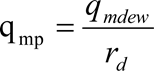
3.2.2. Carbon flow check U.K.
A carbon flow check using actual exhaust is recommended for detecting measurement and control problems and verifying the proper operation of the partial flow system. The carbon flow check should be run at least each time a new engine is installed, or something significant is changed in the test cell configuration.
The engine shall be operated at peak torque load and speed or any other steady state mode that produces 5 % or more of CO 2 . The partial flow sampling system shall be operated with a dilution factor of about 15 to 1.
If a carbon flow check is conducted, the procedure given in Appendix 6 to this Annex shall be applied. The carbon flow rates shall be calculated according to sections 2.1 to 2.3 of Appendix 6 to this Annex. All carbon flow rates should agree to within 6 % of each other.
3.2.3. Pre-test check U.K.
A pre-test check shall be performed within 2 hours before the test run in the following way:
The accuracy of the flow meters shall be checked by the same method as used for calibration (see section 3.2.1) for at least two points, including flow values of q m dw that correspond to dilution ratios between 5 and 15 for the q m dew value used during the test.
If it can be demonstrated by records of the calibration procedure under section 3.2.1 that the flow meter calibration is stable over a longer period of time, the pre-test check may be omitted.
3.3. Determination of transformation time (for partial flow dilution systems on ETC only) U.K.
The system settings for the transformation time evaluation shall be exactly the same as during measurement of the test run. The transformation time shall be determined by the following method:
An independent reference flowmeter with a measurement range appropriate for the probe flow shall be put in series with and closely coupled to the probe. This flowmeter shall have a transformation time of less than 100 ms for the flow step size used in the response time measurement, with flow restriction sufficiently low as to not affect the dynamic performance of the partial flow dilution system, and consistent with good engineering practice.
A step change shall be introduced to the exhaust flow (or air flow if exhaust flow is calculated) input of the partial flow dilution system, from a low flow to at least 90 % of full scale. The trigger for the step change should be the same one used to start the look-ahead control in actual testing. The exhaust flow step stimulus and the flowmeter response shall be recorded at a sample rate of at least 10 Hz.
From this data, the transformation time shall be determined for the partial flow dilution system, which is the time from the initiation of the step stimulus to the 50 % point of the flowmeter response. In a similar manner, the transformation times of the q mp signal of the partial flow dilution system and of the q m ew,i signal of the exhaust flow meter shall be determined. These signals are used in the regression checks performed after each test (see section 3.8.3.2 of Appendix 2 to this Annex).
The calculation shall be repeated for at least 5 rise and fall stimuli, and the results shall be averaged. The internal transformation time (< 100 msec) of the reference flowmeter shall be subtracted from this value. This is the ‘ look-ahead ’ value of the partial flow dilution system, which shall be applied in accordance with section 3.8.3.2 of Appendix 2 to this Annex.
3.4. Checking the partial flow conditions U.K.
The range of the exhaust gas velocity and the pressure oscillations shall be checked and adjusted according to the requirements of section 2.2.1 of Annex V (EP), if applicable.
3.5. Calibration intervals U.K.
The flow measurement instrumentation shall be calibrated at least every 3 months or whenever a system repair or change is made that could influence calibration.]
4.CALIBRATION OF THE SMOKE MEASUREMENT EQUIPMENTU.K.
4.1.IntroductionU.K.
The opacimeter shall be calibrated as often as necessary to fulfil the accuracy requirements of this Directive. The calibration method to be used is described in this section for the components indicated in Annex III, Appendix 4, Section 5 and Annex V, Section 3.
4.2.Calibration procedureU.K.
4.2.1.Warming-up timeU.K.
The opacimeter shall be warmed up and stabilised according to the manufacturer's recommendations. If the opacimeter is equipped with a purge air system to prevent sooting of the instrument optics, this system should also be activated and adjusted according to the manufacturer's recommendations.
4.2.2.Establishment of the linearity responseU.K.
The linearity of the opacimeter shall be checked in the opacity readout mode as per the manufacturer's recommendations. Three neutral density filters of known transmittance, which shall meet the requirements of Annex III, Appendix 4, Section 5.2.5, shall be introduced to the opacimeter and the value recorded. The neutral density filters shall have nominal opacities of approximately 10 %, 20 % and 40 %.
The linearity must not differ by more than ± 2 % opacity from the nominal value of the neutral density filter. Any non-linearity exceeding the above value must be corrected prior to the test.
4.3.Calibration intervalsU.K.
The opacimeter shall be calibrated according to Section 4.2.2 at least every three months or whenever a system repair or change is made that could influence calibration.
[F2Appendix 6 CARBON FLOW CHECK
1. INTRODUCTION U.K.
All but a tiny part of the carbon in the exhaust comes from the fuel, and all but a minimal part of this is manifest in the exhaust gas as CO 2 . This is the basis for a system verification check based on CO 2 measurements.
The flow of carbon into the exhaust measurement systems is determined from the fuel flow rate. The flow of carbon at various sampling points in the emissions and particulate sampling systems is determined from the CO 2 concentrations and gas flow rates at those points.
In this sense, the engine provides a known source of carbon flow, and observing the same carbon flow in the exhaust pipe and at the outlet of the partial flow PM sampling system verifies leak integrity and flow measurement accuracy. This check has the advantage that the components are operating under actual engine test conditions of temperature and flow.
The following diagram shows the sampling points at which the carbon flows shall be checked. The specific equations for the carbon flows at each of the sample points are given below.

2. CALCULATIONS U.K.
2.1. Carbon flow rate into the engine (location 1) U.K.
The carbon mass flow rate into the engine for a fuel CH α O ε is given by:

where:
q mf = fuel mass flow rate, kg/s
2.2. Carbon flow rate in the raw exhaust (location 2) U.K.
The carbon mass flow rate in the exhaust pipe of the engine shall be determined from the raw CO 2 concentration and the exhaust gas mass flow rate:

where:
c CO2,r
=
wet CO 2 concentration in the raw exhaust gas, %
c CO2,a
=
wet CO 2 concentration in the ambient air, % (around 0,04 %)
q m ew
=
exhaust gas mass flow rate on wet basis, kg/s
M re
=
molecular mass of exhaust gas
If CO 2 is measured on a dry basis it shall be converted to a wet basis according to section 5.2 of Appendix 1 to this Annex.
2.3. Carbon flow rate in the dilution system (location 3) U.K.
The carbon flow rate shall be determined from the dilute CO 2 concentration, the exhaust gas mass flow rate and the sample flow rate:

where:
c CO2,d
=
wet CO 2 concentration in the dilute exhaust gas at the outlet of the dilution tunnel, %
c CO2,a
=
wet CO 2 concentration in the ambient air, % (around 0,04 %)
q m dew
=
diluted exhaust gas mass flow rate on wet basis, kg/s
q m ew
=
exhaust gas mass flow rate on wet basis, kg/s (partial flow system only)
q mp
=
sample flow of exhaust gas into partial flow dilution system, kg/s (partial flow system only)
M re
=
molecular mass of exhaust gas
If CO 2 is measured on a dry basis, it shall be converted to wet basis according to section 5.2 of Appendix 1 to this Annex.
2.4. The molecular mass (M re ) of the exhaust gas shall be calculated as follows: U.K.

where:
q m f
=
fuel mass flow rate, kg/s
q m aw
=
intake air mass flow rate on wet basis, kg/s
H a
=
humidity of intake air, g water per kg dry air
M ra
=
molecular mass of dry intake air (= 28,9 g/mol)
α, δ, ε, γ
=
molar ratios referring to a fuel CH α O δ N ε S γ
Alternatively, the following molecular masses may be used:
M re (diesel)
=
28,9 g/mol
M re (LPG)
=
28,6 g/mol
M re (NG)
=
28,3 g/mol]
ANNEX IVU.K.TECHNICAL CHARACTERISTICS OF REFERENCE FUEL PRESCRIBED FOR APPROVAL TESTS AND TO VERIFY CONFORMITY OF PRODUCTION
[F11.1.
Diesel reference fuel for testing engines to the emission limits given in row a of the Tables in Section 6.2.1 of Annex I] a
| a If it is required to calculate the thermal efficiency of an engine or vehicle, the calorific value of the fuel can be calculated from: Specific energy (calorific value)(net) in MJ/kg = (46,423 - 8,792d2 + 3,170d)(1 - (x + y + s)) + 9,420s - 2,499x where, d = the density at 15 °C x = the proportion by mass of water (% divided by 100) y = the proportion by mass of ash (% divided by 100) s = the proportion by mass of sulphur (% divided by 100). | |||||
| b The values quoted in the specification are ‘true values’. In establishment of their limit values the terms of ISO 4259, Petroleums products — Determination and application of precision data in relation to methods of test, have been applied and in fixing a minimum value, a minimum difference of 2R above zero has been taken into account; in fixing a maximum and minimum value, the minimum difference is 4R (R = reproducibility). Notwithstanding this measure, which is necessary for statistical reasons, the manufacturer of a fuel should nevertheless aim at a zero value where the stipulated maximum value is 2R and at the mean value in the case of quotations of maximum and minimum limits. Should it be necessary to clarify the question as to whether a fuel meets the requirements of the specification, the terms of ISO 4259 should be applied. | |||||
| c The range for cetane number is not in accordance with the requirement of a minimum range of 4R. However, in the case of dispute between fuel supplier and fuel user, the terms in ISO 4259 can be used to resolve such disputes provided replicate measurements, of sufficient number to achieve the necessary precision, are made in preference to single determinations. | |||||
| d The month of publication will be completed in due course. | |||||
| e The actual sulphur content of the fuel used for the test shall be reported. In addition, the sulphur content of the reference fuel used to approve a vehicle or engine against the limit values set out in row B of the Table in Section 6.2.1. of Annex I to this Directive shall have a maximum sulphur content of 50 ppm. The Commission will as soon as possible bring forward a modification to this Annex reflecting the market average for fuel sulphur content in respect of the fuel defined in Annex IV to Directive 98/70/EC. | |||||
| f Even though oxidation stability is controlled, it is likely that shelf life will be limited. Advice should be sought from the supplier as to storage conditions and life. | |||||
| g New and better method for polycyclic aromatics under development | |||||
| Parameter | Unit | Limitsb | Test method | Publication | |
|---|---|---|---|---|---|
| Minimum | Maximum | ||||
| Cetane numberc | 52 | 54 | EN-ISO 5165 | 1998d | |
| Density at 15 °C | kg/m3 | 833 | 837 | EN-ISO 3675 | 1995 |
| Distillation: | |||||
| — 50 % point | °C | 245 | — | EN-ISO 3405 | 1998 |
| — 95 % point | °C | 345 | 350 | EN-ISO 3405 | 1998 |
| — final boiling point | °C | — | 370 | EN-ISO 3405 | 1998 |
| Flash point | °C | 55 | — | EN 27719 | 1993 |
| CFPP | °C | — | - 5 | EN 116 | 1981 |
| Viscosity at 40 °C | mm2/s | 2,5 | 3,5 | EN-ISO 3104 | 1996 |
| Polycyclic aromatic hydrocarbons | % m/m | 3,0 | 6,0 | IP 391g | 1995 |
| Sulphur contente | mg/kg | — | 300 | pr. EN-ISO/DIS 14596 | 1998d |
| Copper corrosion | — | 1 | EN-ISO 2160 | 1995 | |
| Conradson carbon residue (10 % DR) | % m/m | — | 0,2 | EN-ISO 10370 | |
| Ash content | % m/m | — | 0,01 | EN-ISO 6245 | 1995 |
| Water content | % m/m | — | 0,05 | EN-ISO 12937 | 1995 |
| Neutralisation (strong acid) number | mg KOH/g | — | 0,02 | ASTM D 974-95 | 1998d |
| Oxidation stabilityf | mg/ml | — | 0,025 | EN-ISO 12205 | 1996 |
| % m/m | — | — | EN 12916 | [2000]d | |
[F21.2. Diesel reference fuel for testing engines to the emission limits given in rows B1, B2 or C of the Tables in Section 6.2.1 of Annex I U.K.
| a The values quoted in the specifications are ‘ true values ’ . In establishment of their limit values the terms of ISO 4259 ‘ Petroleum products – Determination and application of precision data in relation to methods of test ’ have been applied and in fixing a minimum value, a minimum difference of 2R above zero has been taken into account; in fixing a maximum and minimum value, the minimum difference is 4R (R = reproducibility). Notwithstanding this measure, which is necessary for technical reasons, the manufacturer of fuels should nevertheless aim at a zero value where the stipulated maximum value is 2R and at the mean value in the case of quotations of maximum and minimum limits. Should it be necessary to clarify the questions as to whether a fuel meets the requirements of the specifications, the terms of ISO 4259 should be applied. | ||||
| b The range for cetane number is not in accordance with the requirements of a minimum range of 4R. However, in the case of a dispute between fuel supplier and fuel user, the terms of ISO 4259 may be used to resolve such disputes provided replicate measurements, of sufficient number to archive the necessary precision, are made in preference to single determinations. | ||||
| c The actual sulphur content of the fuel used for the Type I test shall be reported. | ||||
| d Even though oxidation stability is controlled, it is likely that shelf life will be limited. Advice should be sought from the supplier as to storage conditions and life.] | ||||
| Parameter | Unit | Limits a | Test Method | |
|---|---|---|---|---|
| minimum | maximum | |||
| Cetane number b | 52,0 | 54,0 | EN-ISO 5165 | |
| Density at 15 °C | kg/m 3 | 833 | 837 | EN-ISO 3675 |
| Distillation: | ||||
| — 50 % point | °C | 245 | — | EN-ISO 3405 |
| — 95 % point | °C | 345 | 350 | EN-ISO 3405 |
| — Final boiling point | °C | — | 370 | EN-ISO 3405 |
| Flash point | °C | 55 | — | EN 22719 |
| CFPP | °C | — | –5 | EN 116 |
| Viscosity at 40 °C | mm 2 /s | 2,3 | 3,3 | EN-ISO 3104 |
| Polycyclic aromatic hydrocarbons | % m/m | 2,0 | 6,0 | IP 391 |
| Sulphur content c | mg/kg | — | 10 | ASTM D 5453 |
| Copper corrosion | — | class 1 | EN-ISO 2160 | |
| Conradson carbon residue (10 % DR) | % m/m | — | 0,2 | EN-ISO 10370 |
| Ash content | % m/m | — | 0,01 | EN-ISO 6245 |
| Water content | % m/m | — | 0,02 | EN-ISO 12937 |
| Neutralisation (strong acid) number | mg KOH/g | — | 0,02 | ASTM D 974 |
| Oxidation stability d | mg/ml | — | 0,025 | EN-ISO 12205 |
| Lubricity (HFRR wear scan diameter at 60 °C) | μm | — | 400 | CEC F-06-A-96 |
| FAME | prohibited | |||
[F11.3.]
Ethanol for diesel enginesa
| a Cetane improver, as specified by the engine manufacturer, may be added to the ethanol fuel. The maximum allowed amount is 10 % m/m. | ||||
| b The values quoted in the specification are ‘true values’. In establishment of their limit values the terms of ISO 4259, Petroleum products — Determination and application of precision data in relation to methods of test, have been applied and in fixing a minimum value, a minimum difference of 2R above zero has been taken into account; in fixing a maximum and minimum value, the minimum difference is 4R (R – reproducibility). Notwithstanding this measure, which is necessary for statistical reasons, the manufacturer of a fuel should nevertheless aim at a zero value where the stipulated maximum value is 2R and at the mean value in the case of quotations of maximum and minimum limits. Should it be necessary to clarify the question as to whether a fuel meets the requirements of the specification, the terms of ISO 4259 should be applied. | ||||
| c Equivalent ISO methods will be adopted when issued for all properties listed above. | ||||
| Parameter | Unit | Limitsb | Test methodc | |
|---|---|---|---|---|
| Minimum | Maximum | |||
| Alcohol, mass | % m/m | 92,4 | — | ASTM D 5501 |
| Other alcohol than ethanol contained in total alcohol, mass | % m/m | — | 2 | ADTM D 5501 |
| Density at 15 °C | kg/m3 | 795 | 815 | ASTM D 4052 |
| Ash content | % m/m | 0,001 | ISO 6245 | |
| Flash point | °C | 10 | ISO 2719 | |
| Acidity, calculated as acetic acid | % m/m | — | 0,0025 | ISO 1388-2 |
| Neutralisation (strong acid) number | KOH mg/l | — | 1 | |
| Colour | According to scale | — | 10 | ASTM D 1209 |
| Dry residue at 100 °C | mg/kg | 15 | ISO 759 | |
| Water content | % m/m | 6,5 | ISO 760 | |
| Aldehydes calculated as acetic acid | % m/m | 0,0025 | ISO 1388-4 | |
| Sulphur content | mg/kg | — | 10 | ASTM D 5453 |
| Esters, calculated as ethylacetate | % m/m | — | 0,1 | ASSTM D 1617 |
2.NATURAL GAS (NG)U.K.
European market fuels are available in two ranges:
the H range, whose extreme reference fuels are GR and G23;
the L range, whose extreme reference fuels are G23 and G25.
The characteristics of GR, G23 and G25 reference fuels are summarised below:
Reference fuel GR
Reference fuel G23
Reference fuel G25
[F13. TECHNICAL DATA OF THE LPG REFERENCE FUELS U.K.
A. Technical data of the LPG reference fuels used for testing vehicles to the emission limits given in row A of the tables in Section 6.2.1 of Annex I U.K.
| a This method may not accurately determine the presence of corrosive materials if the sample contains corrosion inhibitors or other chemicals which diminish the corrosivity of the sample to the copper strip. Therefore, the addition of such compounds for the sole purpose of biasing the test method is prohibited. | ||||
| Parameter | Unit | Fuel A | Fuel B | Test method |
|---|---|---|---|---|
| Composition: | ISO 7941 | |||
| C 3 -content | % vol | 50 ±2 | 85 ±2 | |
| C 4 -content | % vol | balance | balance | |
| < C 3 , >C 4 | % vol | max. 2 | max. 2 | |
| Olefins | % vol | max. 12 | max. 14 | |
| Evaporation residue | mg/kg | max. 50 | max. 50 | ISO 13757 |
| Water at 0 °C | free | Free | visual inspection | |
| Total sulphur content | mg/kg | max. 50 | max. 50 | EN 24260 |
| Hydrogen sulphide | none | none | ISO 8819 | |
| Copper strip corrosion | rating | class 1 | class 1 | ISO 6251 a |
| Odour | characteristic | characteristic | ||
| Motor octane number | min. 92,5 | min. 92,5 | EN 589 Annex B | |
B. Technical data of the LPG reference fuels used for testing vehicles to the emission limits given in row B1, B2 or C of the tables in section 6.2.1 of Annex I U.K.
| a This method may not accurately determine the presence of corrosive materials if the sample contains corrosion inhibitors or other chemicals which diminish the corrosivity of the sample to the copper strip. Therefore, the addition of such compounds for the sole purpose of biasing the test method is prohibited.] | ||||
| Parameter | Unit | Fuel A | Fuel B | Test method |
|---|---|---|---|---|
| Composition: | ISO 7941 | |||
| C 3 -content | % vol | 50 ±2 | 85 ±2 | |
| C 4 -content | % vol | balance | balance | |
| < C 3 , > C 4 | % vol | max. 2 | max. 2 | |
| Olefins | % vol | max. 12 | max. 14 | |
| Evaporation residue | mg/kg | max. 50 | max. 50 | ISO 13757 |
| Water at 0 °C | free | free | Visual inspection | |
| Total sulphur content | mg/kg | max. 10 | max. 10 | EN 24260 |
| Hydrogen sulphide | none | none | ISO 8819 | |
| Copper strip corrosion | rating | class 1 | class 1 | ISO 6251 a |
| Odour | characteristic | characteristic | ||
| Motor octane number | min. 92,5 | min. 92,5 | EN 589 Annex B | |
ANNEX VU.K.ANALYTICAL AND SAMPLING SYSTEMS
1.DETERMINATION OF THE GASEOUS EMISSIONSU.K.
1.1.IntroductionU.K.
Section 1.2 and Figures 7 and 8 contain detailed descriptions of the recommended sampling and analysing systems. Since various configurations can produce equivalent results, exact conformance with Figures 7 and 8 is not required. Additional components such as instruments, valves, solenoids, pumps, and switches may be used to provide additional information and co-ordinate the functions of the component systems. Other components which are not needed to maintain the accuracy on some systems, may be excluded if their exclusion is based upon good engineering judgement.

1.2.Description of the analytical systemU.K.
An analytical system for the determination of the gaseous emissions in the raw (Figure 7, ESC only) or diluted (Figure 8, ETC and ESC) exhaust gas is described based on the use of:
HFID analyser for the measurement of hydrocarbons;
NDIR analysers for the measurement of carbon monoxide and carbon dioxide;
HCLD or equivalent analyser for the measurement of the oxides of nitrogen.
The sample for all components may be taken with one sampling probe or with two sampling probes located in close proximity and internally split to the different analysers. Care must be taken that no condensation of exhaust components (including water and sulphuric acid) occurs at any point of the analytical system.

1.2.1.Components of Figures 7 and 8U.K.
Exhaust gas sampling probe (Figure 7 only)U.K.
A stainless steel straight closed end multi-hole probe is recommended. The inside diameter shall not be greater than the inside diameter of the sampling line. The wall thickness of the probe shall not be greater than 1 mm. There shall be a minimum of three holes in three different radial planes sized to sample approximately the same flow. The probe must extend across at least 80 % of the diameter of the exhaust pipe. One or two sampling probes may be used.
SP2 Diluted exhaust gas HC sampling probe (Figure 8 only)U.K.
The probe shall:
be defined as the first 254 mm to 762 mm of the heated sampling line HSL1;
have a 5 mm minimum inside diameter;
be installed in the dilution tunnel DT (see Section 2.3, Figure 20) at a point where the dilution air and exhaust gas are well mixed (i.e. approximately 10 tunnel diameters downstream of the point where the exhaust enters the dilution tunnel);
be sufficiently distant (radially) from other probes and the tunnel wall so as to be free from the influence of any wakes or eddies;
be heated so as to increase the gas stream temperature to 463 K ± 10 K (190 °C ± 10 °C) at the exit of the probe.
SP3 Diluted exhaust gas CO, CO2, NOx sampling probe (Figure 8 only)U.K.
The probe shall:
be in the same plane as SP2;
be sufficiently distant (radially) from other probes and the tunnel wall so as to be free from the influence of any wakes or eddies;
be heated and insulated over its entire length to a minimum temperature of 328 K (55 °C) to prevent water condensation.
HSL1 Heated sampling lineU.K.
The sampling line provides a gas sample from a single probe to the split point(s) and the HC analyser.
The sampling line shall:
have a 5 mm minimum and a 13,5 mm maximum inside diameter;
be made of stainless steel or PTFE;
maintain a wall temperature of 463 K ± 10 K (190 °C ± 10 °C) as measured at every separately controlled heated section, if the temperature of the exhaust gas at the sampling probe is equal to or below 463 K (190 °C);
maintain a wall temperature greater than 453 K (180 °C), if the temperature of the exhaust gas at the sampling probe is above 463 K (190 °C);
maintain a gas temperature of 463 K ± 10 K (190 °C ± 10 °C) immediately before the heated filter F2 and the HFID.
HSL2 Heated NOx sampling lineU.K.
The sampling line shall:
maintain a wall temperature of 328 K to 473 K (55 °C to 200 °C), up to the converter C when using a cooling bath B, and up to the analyser when a cooling bath B is not used,
be made of stainless steel or PTFE.
SL Sampling line for CO and CO2 U.K.
The line shall be made of PTFE or stainless steel. It may be heated or unheated.
BK Background bag (optional; Figure 8 only)U.K.
For the sampling of the background concentrations.
BG Sample bag (optional; Figure 8 CO and CO2 only)U.K.
For the sampling of the sample concentrations.
F1 Heated pre-filter (optional)U.K.
The temperature shall be the same as HSL1.
F2 Heated filterU.K.
The filter shall extract any solid particles from the gas sample prior to the analyser. The temperature shall be the same as HSL1. The filter shall be changed as needed.
P Heated sampling pumpU.K.
The pump shall be heated to the temperature of HSL1.
HCU.K.
Heated flame ionisation detector (HFID) for the determination of the hydrocarbons. The temperature shall be kept at 453 K to 473 K (180 °C to 200 °C).
CO, CO2 U.K.
NDIR analysers for the determination of carbon monoxide and carbon dioxide (optional for the determination of the dilution ratio for PT measurement).
NOU.K.
CLD or HCLD analyser for the determination of the oxides of nitrogen. If a HCLD is used it shall be kept at a temperature of 328 K to 473 K (55 °C to 200 °C).
C ConverterU.K.
A converter shall be used for the catalytic reduction of NO2 to NO prior to analysis in the CLD or HCLD.
B Cooling bath (optional)U.K.
To cool and condense water from the exhaust sample. The bath shall be maintained at a temperature of 273 K to 277 K (0 °C to 4 °C) by ice or refrigeration. It is optional if the analyser is free from water vapour interference as determined in Annex III, Appendix 5, Sections 1.9.1 and 1.9.2. If water is removed by condensation, the sample gas temperature or dew point shall be monitored either within the water trap or downstream. The sample gas temperature or dew point must not exceed 280 K (7 °C). Chemical dryers are not allowed for removing water from the sample.
T1, T2, T3 Temperature sensorU.K.
To monitor the temperature of the gas stream.
T4 Temperature sensorU.K.
To monitor the temperature of the NO2-NO converter.
T5 Temperature sensorU.K.
To monitor the temperature of the cooling bath.
G1, G2, G3 Pressure gaugeU.K.
To measure the pressure in the sampling lines.
R1, R2 Pressure regulatorU.K.
To control the pressure of the air and the fuel, respectively, for the HFID.
R3, R4, R5 Pressure regulatorU.K.
To control the pressure in the sampling lines and the flow to the analysers.
FL1, FL2, FL3 FlowmeterU.K.
To monitor the sample by-pass flow rate.
FL4 to FL6 Flowmeter (optional)U.K.
To monitor the flow rate through the analysers.
V1 to V5 Selector valveU.K.
Suitable valving for selecting sample, span gas or zero gas flow to the analysers.
V6, V7 Solenoid valveU.K.
To by-pass the NO2-NO converter.
V8 Needle valveU.K.
To balance the flow through the NO2-NO converter C and the by-pass.
V9, V10 Needle valveU.K.
To regulate the flows to the analysers.
V11, V12 Toggle valve (optional)U.K.
To drain the condensate from the bath B.
1.3.NMHC analysis (NG fuelled gas engines only)U.K.
1.3.1.Gas chromatographic method (GC, Figure 9)U.K.
When using the GC method, a small measured volume of a sample is injected onto an analytical column through which it is swept by an inert carrier gas. The column separates various components according to their boiling points so that they elute from the column at different times. They then pass through a detector which gives an electrical signal that depends on their concentration. Since it is not a continuous analysis technique, it can only be used in conjunction with the bag sampling method as described in Annex III, Appendix 4, Section 3.4.2.
For NMHC an automated GC with a FID shall be used. The exhaust gas shall be sampled into a sampling bag from which a part shall be taken and injected into the GC. The sample is separated into two parts (CH4/Air/CO and NMHC/CO2/H2O) on the Porapak column. The molecular sieve column separates CH4 from the air and CO before passing it to the FID where its concentration is measured. A complete cycle from injection of one sample to injection of a second can be made in 30 s. To determine NMHC, the CH4 concentration shall be subtracted from the total HC concentration (see Annex III, Appendix 2, Section 4.3.1).
Figure 9 shows a typical GC assembled to routinely determine CH4. Other GC methods can also be used based on good engineering judgement.
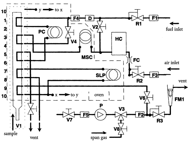
Components of Figure 9U.K.
PC Porapak columnU.K.
Porapak N, 180/300 μm (50/80 mesh), 610 mm length × 2,16 mm ID shall be used and conditioned at least 12 h at 423 K (150 °C) with carrier gas prior to initial use.
MSC Molecular sieve columnU.K.
Type 13X, 250/350 μm (45/60 mesh), 1 220 mm length × 2,16 mm ID shall be used and conditioned at least 12 h at 423 K (150 °C) with carrier gas prior to initial use.
OV OvenU.K.
To maintain columns and valves at stable temperature for analyser operation, and to condition the columns at 423 K (150 °C).
SLP Sample loopU.K.
A sufficient length of stainless steel tubing to obtain approximately 1 cm3 volume.
P PumpU.K.
To bring the sample to the gas chromatograph.
D DryerU.K.
A dryer containing a molecular sieve shall be used to remove water and other contaminants which might be present in the carrier gas.
HCU.K.
Flame ionisation detector (FID) to measure the concentration of methane.
V1 Sample injection valveU.K.
To inject the sample taken from the sampling bag via SL of Figure 8. It shall be low dead volume, gas tight, and heatable to 423 K (150 C).
V3 Selector valveU.K.
To select span gas, sample, or no flow.
V2, V4, V5, V6, V7, V8 Needle valveU.K.
To set the flows in the system.
R1, R2, R3 Pressure regulatorU.K.
To control the flows of the fuel (= carrier gas), the sample, and the air, respectively.
FC Flow capillaryU.K.
To control the rate of air flow to the FID.
G1, G2, G3 Pressure gaugeU.K.
To control the flows of the fuel (= carrier gas), the sample, and the air, respectively.
F1, F2, F3, F4, F5 FilterU.K.
Sintered metal filters to prevent grit from entering the pump or the instrument.
FL1U.K.
To measure the sample by-pass flow rate.
1.3.2.Non-methane cutter method (NMC, Figure 10)U.K.
The cutter oxidises all hydrocarbons except CH4 to CO2 and H2O, so that by passing the sample through the NMC only CH4 is detected by the FID. If bag sampling is used, a flow diverter system shall be installed at SL (see Section 1.2, Figure 8) with which the flow can be alternatively passed through or around the cutter according to the upper part of Figure 10. For NMHC measurement, both values (HC and CH4) shall be observed on the FID and recorded. If the integration method is used, an NMC in line with a second FID shall be installed parallel to the regular FID into HSL1 (see Section 1.2, Figure 8) according to the lower part of Figure 10. For NMHC measurement, the values of the two FID's (HC and CH4) shall be observed and recorded.
The cutter shall be characterised at or above 600 K (327 °C) prior to test work with respect to its catalytic effect on CH4 and C2H6 at H2O values representative of exhaust stream conditions. The dewpoint and O2 level of the sampled exhaust stream must be known. The relative response of the FID to CH4 must be recorded (see Annex III, Appendix 5, Section 1.8.2).

Components of Figure 10U.K.
NMC Non-methane cutterU.K.
To oxidise all hydrocarbons except methane.
HCU.K.
Heated flame ionisation detector (HFID) to measure the HC and CH4 concentrations. The temperature shall be kept at 453 K to 473 K (180 °C to 200 °C).
V1 Selector valveU.K.
To select sample, zero and span gas. V1 is identical with V2 of Figure 8.
V2, V3 Solenoid valveU.K.
To by-pass the NMC.
V4 Needle valveU.K.
To balance the flow through the NMC and the by-pass.
R1 Pressure regulatorU.K.
To control the pressure in the sampling line and the flow to the HFID. R1 is identical with R3 of Figure 8.
FL1 FlowmeterU.K.
To measure the sample by-pass flow rate. FL1 is identical with FL1 of Figure 8.
2.EXHAUST GAS DILUTION AND DETERMINATION OF THE PARTICULATESU.K.
2.1.IntroductionU.K.
Sections 2.2, 2.3 and 2.4 and Figures 11 to 22 contain detailed descriptions of the recommended dilution and sampling systems. Since various configurations can produce equivalent results, exact conformance with these figures is not required. Additional components such as instruments, valves, solenoids, pumps, and switches may be used to provide additional information and coordinate the functions of the component systems. Other components which are not needed to maintain the accuracy on some systems, may be excluded if their exclusion is based upon good engineering judgement.
2.2.Partial flow dilution systemU.K.
A dilution system is described in Figures 11 to 19 based upon the dilution of a part of the exhaust stream. Splitting of the exhaust stream and the following dilution process may be done by different dilution system types. For subsequent collection of the particulates, the entire dilute exhaust gas or only a portion of the dilute exhaust gas is passed to the particulate sampling system (Section 2.4, Figure 21). The first method is referred to as total sampling type, the second method as fractional sampling type.
The calculation of the dilution ratio depends upon the type of system used. The following types are recommended:
Isokinetic systems (Figures 11, 12)U.K.
With these systems, the flow into the transfer tube is matched to the bulk exhaust flow in terms of gas velocity and/or pressure, thus requiring an undisturbed and uniform exhaust flow at the sampling probe. This is usually achieved by using a resonator and a straight approach tube upstream of the sampling point. The split ratio is then calculated from easily measurable values like tube diameters. It should be noted that isokinesis is only used for matching the flow conditions and not for matching the size distribution. The latter is typically not necessary, as the particles are sufficiently small as to follow the fluid streamlines.
Flow controlled systems with concentration measurement (Figures 13 to 17)U.K.
With these systems, a sample is taken from the bulk exhaust stream by adjusting the dilution air flow and the total dilute exhaust flow. The dilution ratio is determined from the concentrations of tracer gases, such as CO2 or NOx naturally occurring in the engine exhaust. The concentrations in the dilute exhaust gas and in the dilution air are measured, whereas the concentration in the raw exhaust gas can be either measured directly or determined from fuel flow and the carbon balance equation, if the fuel composition is known. The systems may be controlled by the calculated dilution ratio (Figures 13, 14) or by the flow into the transfer tube (Figures 12, 13, 14).
Flow controlled systems with flow measurement (Figures 18, 19)U.K.
With these systems, a sample is taken from the bulk exhaust stream by setting the dilution air flow and the total dilute exhaust flow. The dilution ratio is determined from the difference of the two flows rates. Accurate calibration of the flow meters relative to one another is required, since the relative magnitude of the two flow rates can lead to significant errors at higher dilution ratios (of 15 and above). Flow control is very straight forward by keeping the dilute exhaust flow rate constant and varying the dilution air flow rate, if needed.
When using partial flow dilution systems, attention must be paid to avoiding the potential problems of loss of particulates in the transfer tube, ensuring that a representative sample is taken from the engine exhaust, and determination of the split ratio. The systems described pay attention to these critical areas.

Raw exhaust gas is transferred from the exhaust pipe EP to the dilution tunnel DT through the transfer tube TT by the isokinetic sampling probe ISP. The differential pressure of the exhaust gas between exhaust pipe and inlet to the probe is measured with the pressure transducer DPT. This signal is transmitted to the flow controller FC1 that controls the suction blower SB to maintain a differential pressure of zero at the tip of the probe. Under these conditions, exhaust gas velocities in EP and ISP are identical, and the flow through ISP and TT is a constant fraction (split) of the exhaust gas flow. The split ratio is determined from the cross-sectional areas of EP and ISP. The dilution air flow rate is measured with the flow measurement device FM1. The dilution ratio is calculated from the dilution air flow rate and the split ratio.

Raw exhaust gas is transferred from the exhaust pipe EP to the dilution tunnel DT through the transfer tube TT by the isokinetic sampling probe ISP. The differential pressure of the exhaust gas between exhaust pipe and inlet to the probe is measured with the pressure transducer DPT. This signal is transmitted to the flow controller FC1 that controls the pressure blower PB to maintain a differential pressure of zero at the tip of the probe. This is done by taking a small fraction of the dilution air whose flow rate has already been measured with the flow measurement device FM1, and feeding it to TT by means of a pneumatic orifice. Under these conditions, exhaust gas velocities in EP and ISP are identical, and the flow through ISP and TT is a constant fraction (split) of the exhaust gas flow. The split ratio is determined from the cross sectional areas of EP and ISP. The dilution air is sucked through DT by the suction blower SB, and the flow rate is measured with FM1 at the inlet to DT. The dilution ratio is calculated from the dilution air flow rate and the split ratio.

Raw exhaust gas is transferred from the exhaust pipe EP to the dilution tunnel DT through the sampling probe SP and the transfer tube TT. The concentrations of a tracer gas (CO2 or NOx) are measured in the raw and diluted exhaust gas as well as in the dilution air with the exhaust gas analyser(s) EGA. These signals are transmitted to the flow controller FC2 that controls either the pressure blower PB or the suction blower SB to maintain the desired exhaust split and dilution ratio in DT. The dilution ratio is calculated from the tracer gas concentrations in the raw exhaust gas, the diluted exhaust gas, and the dilution air.

Raw exhaust gas is transferred from the exhaust pipe EP to the dilution tunnel DT through the sampling probe SP and the transfer tube TT. The CO2 concentrations are measured in the diluted exhaust gas and in the dilution air with the exhaust gas analyser(s) EGA. The CO2 and fuel flow GFUEL signals are transmitted either to the flow controller FC2, or to the flow controller FC3 of the particulate sampling system (see Figure 21). FC2 controls the pressure blower PB, FC3 the sampling pump P (see Figure 21), thereby adjusting the flows into and out of the system so as to maintain the desired exhaust split and dilution ratio in DT. The dilution ratio is calculated from the CO2 concentrations and GFUEL using the carbon balance assumption.
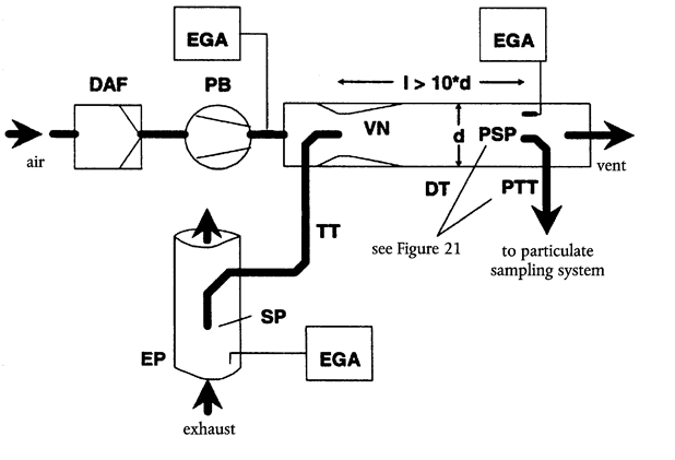
Raw exhaust gas is transferred from the exhaust pipe EP to the dilution tunnel DT through the sampling probe SP and the transfer tube TT due to the negative pressure created by the venturi VN in DT. The gas flow rate through TT depends on the momentum exchange at the venturi zone, and is therefore affected by the absolute temperature of the gas at the exit of TT. Consequently, the exhaust split for a given tunnel flow rate is not constant, and the dilution ratio at low load is slightly lower than at high load. The tracer gas concentrations (CO2 or NOx) are measured in the raw exhaust gas, the diluted exhaust gas, and the dilution air with the exhaust gas analyser(s) EGA, and the dilution ratio is calculated from the values so measured.

Raw exhaust gas is transferred from the exhaust pipe EP to the dilution tunnel DT through the sampling probe SP and the transfer tube TT by a flow divider that contains a set of orifices or venturis. The first one (FD1) is located in EP, the second one (FD2) in TT. Additionally, two pressure control valves (PCV1 and PCV2) are necessary to maintain a constant exhaust split by controlling the backpressure in EP and the pressure in DT. PCV1 is located downstream of SP in EP, PCV2 between the pressure blower PB and DT. The tracer gas concentrations (CO2 or NOx) are measured in the raw exhaust gas, the diluted exhaust gas, and the dilution air with the exhaust gas analyser(s) EGA. They are necessary for checking the exhaust split, and may be used to adjust PCV1 and PCV2 for precise split control. The dilution ratio is calculated from the tracer gas concentrations.

Raw exhaust gas is transferred from the exhaust pipe EP to the dilution tunnel DT through the transfer tube TT by the flow divider FD3 that consists of a number of tubes of the same dimensions (same diameter, length and bend radius) installed in EP. The exhaust gas through one of these tubes is lead to DT, and the exhaust gas through the rest of the tubes is passed through the damping chamber DC. Thus, the exhaust split is determined by the total number of tubes. A constant split control requires a differential pressure of zero between DC and the outlet of TT, which is measured with the differential pressure transducer DPT. A differential pressure of zero is achieved by injecting fresh air into DT at the outlet of TT. The tracer gas concentrations (CO2 or NOx) are measured in the raw exhaust gas, the diluted exhaust gas, and the dilution air with the exhaust gas analyser(s) EGA. They are necessary for checking the exhaust split and may be used to control the injection air flow rate for precise split control. The dilution ratio is calculated from the tracer gas concentrations.
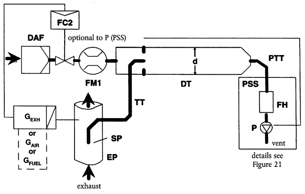
Raw exhaust gas is transferred from the exhaust pipe EP to the dilution tunnel DT through the sampling probe SP and the transfer tube TT. The total flow through the tunnel is adjusted with the flow controller FC3 and the sampling pump P of the particulate sampling system (see Figure 18). The dilution air flow is controlled by the flow controller FC2, which may use GEXHW, GAIRW, or GFUEL as command signals, for the desired exhaust split. The sample flow into DT is the difference of the total flow and the dilution air flow. The dilution air flow rate is measured with the flow measurement device FM1, the total flow rate with the flow measurement device FM3 of the particulate sampling system (see Figure 21). The dilution ratio is calculated from these two flow rates.

Raw exhaust gas is transferred from the exhaust pipe EP to the dilution tunnel DT through the sampling probe SP and the transfer tube TT. The exhaust split and the flow into DT is controlled by the flow controller FC2 that adjusts the flows (or speeds) of the pressure blower PB and the suction blower SB, accordingly. This is possible since the sample taken with the particulate sampling system is returned into DT. GEXHW, GAIRW, or GFUEL may be used as command signals for FC2. The dilution air flow rate is measured with the flow measurement device FM1, the total flow with the flow measurement device FM2. The dilution ratio is calculated from these two flow rates.
2.2.1.Components of Figures 11 to 19U.K.
EP Exhaust pipeU.K.
The exhaust pipe may be insulated. To reduce the thermal inertia of the exhaust pipe a thickness to diameter ratio of 0,015 or less is recommended. The use of flexible sections shall be limited to a length to diameter ratio of 12 or less. Bends shall be minimised to reduce inertial deposition. If the system includes a test bed silencer the silencer may also be insulated.
For an isokinetic system, the exhaust pipe must be free of elbows, bends and sudden diameter changes for at least 6 pipe diameters upstream and 3 pipe diameters downstream of the tip of the probe. The gas velocity at the sampling zone must be higher than 10 m/s except at idle mode. Pressure oscillations of the exhaust gas must not exceed ± 500 Pa on the average. Any steps to reduce pressure oscillations beyond using a chassis-type exhaust system (including silencer and aftertreatment devices) must not alter engine performance nor cause the deposition of particulates.
For systems without isokinetic probe, it is recommended to have a straight pipe of 6 pipe diameters upstream and 3 pipe diameters downstream of the tip of the probe.
SP Sampling probe (Figures 10, 14, 15, 16, 18, 19)U.K.
The minimum inside diameter shall be 4 mm. The minimum diameter ratio between exhaust pipe and probe shall be 4. The probe shall be an open tube facing upstream on the exhaust pipe centreline, or a multiple hole probe as described under SP1 in Section 1.2.1, Figure 5.
ISP Isokinetic sampling probe (Figures 11, 12)U.K.
The isokinetic sampling probe must be installed facing upstream on the exhaust pipe centreline where the flow conditions in section EP are met, and designed to provide a proportional sample of the raw exhaust gas. The minimum inside diameter shall be 12 mm.
A control system is necessary for isokinetic exhaust splitting by maintaining a differential pressure of zero between EP and ISP. Under these conditions exhaust gas velocities in EP and ISP are identical and the mass flow through ISP is a constant fraction of the exhaust gas flow. ISP has to be connected to a differential pressure transducer DPT. The control to provide a differential pressure of zero between EP and ISP is done with the flow controller FC1.
FD1, FD2 Flow divider (Figure 16)U.K.
A set of venturis or orifices is installed in the exhaust pipe EP and in the transfer tube TT, respectively, to provide a proportional sample of the raw exhaust gas. A control system consisting of two pressure control valves PCV1 and PCV2 is necessary for proportional splitting by controlling the pressures in EP and DT.
FD3 Flow divider (Figure 17)U.K.
A set of tubes (multiple tube unit) is installed in the exhaust pipe EP to provide a proportional sample of the raw exhaust gas. One of the tubes feeds exhaust gas to the dilution tunnel DT, whereas the other tubes exit exhaust gas to a damping chamber DC. The tubes must have the same dimensions (same diameter, length, bend radius), so that the exhaust split depends on the total number of tubes. A control system is necessary for proportional splitting by maintaining a differential pressure of zero between the exit of the multiple tube unit into DC and the exit of TT. Under these conditions, exhaust gas velocities in EP and FD3 are proportional, and the flow TT is a constant fraction of the exhaust gas flow. The two points have to be connected to a differential pressure transducer DPT. The control to provide a differential pressure of zero is done with the flow controller FC1.
EGA Exhaust gas analyser (Figures 13, 14, 15, 16, 17)U.K.
CO2 or NOx analysers may be used (with carbon balance method CO2 only). The analysers shall be calibrated like the analysers for the measurement of the gaseous emissions. One or several analysers may be used to determine the concentration differences. The accuracy of the measuring systems has to be such that the accuracy of GEDFW,i is within ± 4 %.
TT Transfer tube (Figures 11 to 19)U.K.
The transfer tube shall be:
as short as possible, but not more than 5 m in length,
equal to or greater than the probe diameter, but not more than 25 mm in diameter,
exiting on the centreline of the dilution tunnel and pointing downstream.
If the tube is 1 meter or less in length, it shall be insulated with material with a maximum thermal conductivity of 0,05 W/m*K with a radial insulation thickness corresponding to the diameter of the probe. If the tube is longer than 1 meter, it must be insulated and heated to a minimum wall temperature of 523 K (250 °C).
DPT Differential pressure transducer (Figures 11, 12, 17)U.K.
The differential pressure transducer shall have a range of ± 500 Pa or less.
FC1 Flow controller (Figures 11, 12, 17)U.K.
For isokinetic systems (Figures 11,12), a flow controller is necessary to maintain a differential pressure of zero between EP and ISP. The adjustment can be done by:
(a)
controlling the speed or flow of the suction blower SB and keeping the speed or flow of the pressure blower PB constant during each mode (Figure 11); or
(b)
adjusting the suction blower SB to a constant mass flow of the diluted exhaust gas and controlling the flow of the pressure blower PB, and therefore the exhaust sample flow in a region at the end of the transfer tube TT (Figure 12).
In the case of a pressure controlled system the remaining error in the control loop must not exceed ± 3 Pa. The pressure oscillations in the dilution tunnel must not exceed ± 250 Pa on the average.
For a multi-tube system (Figure 17), a flow controller is necessary for proportional exhaust splitting to maintain a differential pressure of zero between the exit of the multi-tube unit and the exit of TT. The adjustment is done by controlling the injection air flow rate into DT at the exit of TT.
PCV1, PCV2 Pressure control valve (Figure 16)U.K.
Two pressure control valves are necessary for the twin venturi/twin orifice system for proportional flow splitting by controlling the backpressure of EP and the pressure in DT. The valves shall be located downstream of SP in EP and between PB and DT.
DC Damping chamber (Figure 17)U.K.
A damping chamber shall be installed at the exit of the multiple tube unit to minimise the pressure oscillations in the exhaust pipe EP.
VN Venturi (Figure 15)U.K.
A venturi is installed in the dilution tunnel DT to create a negative pressure in the region of the exit of the transfer tube TT. The gas flow rate through TT is determined by the momentum exchange at the venturi zone, and is basically proportional to the flow rate of the pressure blower PB leading to a constant dilution ratio. Since the momentum exchange is affected by the temperature at the exit of TT and the pressure difference between EP and DT, the actual dilution ratio is slightly lower at low load than at high load.
FC2 Flow controller (Figures 13, 14, 18, 19, optional)U.K.
A flow controller may be used to control the flow of the pressure blower PB and/or the suction blower SB. It may be connected to the exhaust, intake air, or fuel flow signals and/or to the CO2 or NOx differential signals. When using a pressurised air supply (Figure 18), FC2 directly controls the air flow.
FM1 Flow measurement device (Figures 11, 12, 18, 19)U.K.
Gas meter or other flow instrumentation to measure the dilution air flow. FM1 is optional if the pressure blower PB is calibrated to measure the flow.
FM2 Flow measurement device (Figure 19)U.K.
Gas meter or other flow instrumentation to measure the diluted exhaust gas flow. FM2 is optional if the suction blower SB is calibrated to measure the flow.
PB Pressures blower (Figures 11, 12, 13, 14, 15, 16, 19)U.K.
To control the dilution air flow rate, PB may be connected to the flow controllers FC1 or FC2. PB is not required when using a butterfly valve. PB may be used to to measure the dilution air flow, if calibrated.
SB Suction blower (Figures 11, 12, 13, 16, 17, 19)U.K.
For fractional sampling systems only. SB may be used to measure the diluted exhaust gas flow, if calibrated.
DAF Dilution air filter (Figures 11 to 19)U.K.
It is recommended that the dilution air be filtered and charcoal scrubbed to eliminate background hydrocarbons. At the engine manufacturers request the dilution air shall be sampled according to good engineering practice to determine the background particulate levels, which can then be subtracted from the values measured in the diluted exhaust.
DT Dilution tunnel (Figures 11 to 19)U.K.
The dilution tunnel:
shall be of a sufficient length to cause complete mixing of the exhaust and dilution air under turbulent flow conditions;
shall be constructed of stainless steel with:
thickness/diameter ratio of 0,025 or less for dilution tunnels with inside diameters greater than 75 mm;
a nominal thickness of no less then 1,5 mm for dilution tunnels with inside diameters of equal to or less than 75 mm;
shall be at least 75 mm in diameter for the fractional sampling type;
is recommended to be at least 25 mm in diameter for the total sampling type;
may be heated to no greater than 325 K (52 °C) wall temperature by direct heating or by dilution air pre-heating, provided the air temperature does not exceed 325 K (52 °C) prior to the introduction of the exhaust in the dilution tunnel;
may be insulated.
The engine exhaust shall be thoroughly mixed with the dilution air. For fractional sampling systems, the mixing quality shall be checked after introduction into service by means of a CO2-profile of the tunnel with the engine running (at least four equally spaced measuring points). If necessary, a mixing orifice may be used.
Note:U.K.
If the ambient temperature in the vicinity of the dilution tunnel (DT) is below 293K (20 °C), precautions should be taken to avoid particle losses onto the cool walls of the dilution tunnel. Therefore, heating and/or insulating the tunnel within the limits given above is recommended.U.K.
At high engine loads, the tunnel may be cooled by a non-aggressive means such as a circulating fan, as long as the temperature of the cooling medium is not below 293K (20 °C).U.K.
HE Heat exchanger (Figures 16, 17)U.K.
The heat exchanger shall be of sufficient capacity to maintain the temperature at the inlet to the suction blower SB within ± 11K of the average operating temperature observed during the test.
2.3.Full flow dilution systemU.K.
A dilution system is described in Figure 20 based upon the dilution of the total exhaust using the CVS (Constant Volume Sampling) concept. The total volume of the mixture of exhaust and dilution air must be measured. Either a PDP or a CFV system may be used.
For subsequent collection of the particulates, a sample of the dilute exhaust gas is passed to the particulate sampling system (section 2.4, figures 21 and 22). If this is done directly, it is referred to as single dilution. If the sample is diluted once more in the secondary dilution tunnel, it is referred to as double dilution. This is useful, if the filter face temperature requirement cannot be met with single dilution. Although partly a dilution system, the double dilution system is described as a modification of a particulate sampling system in section 2.4, Figure 22, since it shares most of the parts with a typical particulate sampling system.

The total amount of raw exhaust gas is mixed in the dilution tunnel DT with the dilution air. The diluted exhaust gas flow rate is measured either with a Positive Displacement Pump PDP or with a Critical Flow Venturi CFV. A heat exchanger HE or electronic flow compensation EFC may be used for proportional particulate sampling and for flow determination. Since particulate mass determination is based on the total diluted exhaust gas flow, the dilution ratio is not required to be calculated.
2.3.1.Components of Figure 20U.K.
EP Exhaust pipeU.K.
The exhaust pipe length from the exit of the engine exhaust manifold, turbocharger outlet or aftertreatment device to the dilution tunnel shall not exceed 10 m. If the exhaust pipe downstream of the engine exhaust manifold, turbocharger outlet or aftertreatment device exceeds 4 m in length, then all tubing in excess of 4 m shall be insulated, except for an in-line smokemeter, if used. The radial thickness of the insulation must be at least 25 mm. The thermal conductivity of the insulating material must have a value no greater than 0,1 W/mK measured at 673 K (400 °C). To reduce the thermal inertia of the exhaust pipe a thickness to diameter ratio of 0,015 or less is recommended. The use of flexible sections shall be limited to a length to diameter ratio of 12 or less.
PDP Positive displacement pumpU.K.
The PDP meters total diluted exhaust flow from the number of the pump revolutions and the pump displacement. The exhaust system backpressure must not be artificially lowered by the PDP or dilution air inlet system. Static exhaust backpressure measured with the PDP system operating shall remain within ± 1,5 kPa of the static pressure measured without connection to the PDP at identical engine speed and load. The gas mixture temperature immediately ahead of the PDP shall be within ± 6 K of the average operating temperature observed during the test, when no flow compensation is used. Flow compensation may only be used if the temperature at the inlet to the PDP does not exceed 323K (50 °C).
CFV Critical Flow VenturiU.K.
CFV measures total diluted exhaust flow by maintaining the flow at choked conditions (critical flow). Static exhaust backpressure measured with the CFV system operating shall remain within ± 1,5 kPa of the static pressure measured without connection to the CFV at identical engine speed and load. The gas mixture temperature immediately ahead of the CFV shall be within ± 11 K of the average operating temperature observed during the test, when no flow compensation is used.
HE Heat exchanger (optional, if EFC is used)U.K.
The heat exchanger shall be of sufficient capacity to maintain the temperature within the limits required above.
EFC Electronic flow compensation (optional, if HE is used)U.K.
If the temperature at the inlet to either the PDP or CFV is not kept within the limits stated above, a flow compensation system is required for continuous measurement of the flow rate and control of the proportional sampling in the particulate system. To that purpose, the continuously measured flow rate signals are used to correct the sample flow rate through the particulate filters of the particulate sampling system (see Section 2.4, Figures 21, 22), accordingly.
DT Dilution tunnelU.K.
The dilution tunnel:
shall be small enough in diameter to cause turbulent flow (Reynolds Number greater than 4 000) and of sufficient length to cause complete mixing of the exhaust and dilution air; a mixing orifice may be used;
shall be at least 460 mm in diameter with a single dilution system;
shall be at least 210 mm in diameter with a double dilution system;
may be insulated.
The engine exhaust shall be directed downstream at the point where it is introduced into the dilution tunnel, and thoroughly mixed.
When using single dilution, a sample from the dilution tunnel is transferred to the particulate sampling system (Section 2.4, Figure 21). The flow capacity of the PDP or CFV must be sufficient to maintain the diluted exhaust at a temperature of less than or equal to 325 K (52 °C) immediately before the primary particulate filter.
When using double dilution, a sample from the dilution tunnel is transferred to the secondary dilution tunnel where it is further diluted, and then passed through the sampling filters (Section 2.4, Figure 22). The flow capacity of the PDP or CFV must be sufficient to maintain the diluted exhaust stream in the DT at a temperature of less than or equal to 464 K (191 °C) at the sampling zone. The secondary dilution system must provide sufficient secondary dilution air to maintain the doubly-diluted exhaust stream at a temperature of less than or equal to 325 K (52 °C) immediately before the primary particulate filter.
DAF Dilution air filterU.K.
It is recommended that the dilution air be filtered and charcoal scrubbed to eliminate background hydrocarbons. At the engine manufacturers request the dilution air shall be sampled according to good engineering practice to determine the background particulate levels, which can then be subtracted from the values measured in the diluted exhaust.
PSP Particulate sampling probeU.K.
The probe is the leading section of PTT and:
shall be installed facing upstream at a point where the dilution air and exhaust gas are well mixed, i.e. on the dilution tunnel (DT) centreline approximately 10 tunnel diameters downstream of the point where the exhaust enters the dilution tunnel;
shall be of 12 mm minimum inside diameter;
may be heated to no greater than 325 K (52 °C) wall temperature by direct heating or by dilution air pre-heating, provided the air temperature does not exceed 325 K (52 °C) prior to the introduction of the exhaust in the dilution tunnel;
may be insulated.
2.4.Particulate sampling systemU.K.
The particulate sampling system is required for collecting the particulates on the particulate filter. In the case of total sampling partial flow dilution, which consists of passing the entire diluted exhaust sample through the filters, dilution (Section 2.2, Figures 14, 18) and sampling system usually form an integral unit. In the case of fractional sampling partial flow dilution or full flow dilution, which consists of passing through the filters only a portion of the diluted exhaust, the dilution (Section 2.2, Figures 11, 12, 13, 15, 16, 17, 19; Section 2.3, Figure 20) and sampling systems usually form different units.
In this Directive, the double dilution system (Figure 22) of a full flow dilution system is considered as a specific modification of a typical particulate sampling system as shown in Figure 21. The double dilution system includes all important parts of the particulate sampling system, like filter holders and sampling pump.
In order to avoid any impact on the control loops, it is recommended that the sample pump be running throughout the complete test procedure. For the single filter method, a bypass system shall be used for passing the sample through the sampling filters at the desired times. Interference of the switching procedure on the control loops must be minimised.

A sample of the diluted exhaust gas is taken from the dilution tunnel DT of a partial flow or full flow dilution system through the particulate sampling probe PSP and the particulate transfer tube PTT by means of the sampling pump P. The sample is passed through the filter holder(s) FH that contain the particulate sampling filters. The sample flow rate is controlled by the flow controller FC3. If electronic flow compensation EFC (see Figure 20) is used, the diluted exhaust gas flow is used as command signal for FC3.
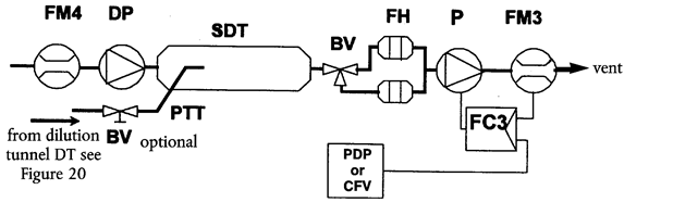
A sample of the diluted exhaust gas is transferred from the dilution tunnel DT of a full flow dilution system through the particulate sampling probe PSP and the particulate transfer tube PTT to the secondary dilution tunnel SDT, where it is diluted once more. The sample is then passed through the filter holder(s) FH that contain the particulate sampling filters. The dilution air flow rate is usually constant whereas the sample flow rate is controlled by the flow controller FC3. If electronic flow compensation EFC (see Figure 20) is used, the total diluted exhaust gas flow is used as command signal for FC3.
2.4.1.Components of Figures 21 and 22U.K.
PTT Particulate transfer tube (Figures 21, 22)U.K.
The particulate transfer tube must not exceed 1 020 mm in length, and must be minimised in length whenever possible. Where applicable (i.e. for partial flow dilution fractional sampling systems and for full flow dilution systems), the length of the sampling probes (SP, ISP, PSP, respectively, see Sections 2.2 and 2.3) shall be included.
The dimensions are valid for:
the partial flow dilution fractional sampling type and the full flow single dilution system from the tip of the probe (SP, ISP, PSP, respectively) to the filter holder;
the partial flow dilution total sampling type from the end of the dilution tunnel to the filter holder;
the full flow double dilution system from the tip of the probe (PSP) to the secondary dilution tunnel.
The transfer tube:
may be heated to no greater than 325 K (52 °C) wall temperature by direct heating or by dilution air pre-heating, provided the air temperature does not exceed 325 K (52 °C) prior to the introduction of the exhaust in the dilution tunnel;
may be insulated.
SDT Secondary dilution tunnel (Figure 22)U.K.
The secondary dilution tunnel should have a minimum diameter of 75 mm, and should be of sufficient length so as to provide a residence time of at least 0,25 seconds for the doubly-diluted sample. The primary filter holder FH shall be located within 300 mm of the exit of the SDT.
The secondary dilution tunnel:
may be heated to no greater than 325 K (52 °C) wall temperature by direct heating or by dilution air pre-heating, provided the air temperature does not exceed 325 K (52 °C) prior to the introduction of the exhaust in the dilution tunnel;
may be insulated.
FH Filter holder(s) (Figures 21, 22)U.K.
For primary and back-up filters one filter housing or separate filter housings may be used. The requirements of Annex III, Appendix 4, Section 4.1.3 shall be met.
The filter holder(s):
may be heated to no greater than 325 K (52 °C) wall temperature by direct heating or by dilution air pre-heating, provided the air temperature does not exceed 325 K (52 °C) prior to the introduction of the exhaust in the dilution tunnel;
may be insulated.
P Sampling pump (Figures 21, 22)U.K.
The particulate sampling pump shall be located sufficiently distant from the tunnel so that the inlet gas temperature is maintained constant (± 3 K), if flow correction by FC3 is not used.
DP Dilution air pump (Figure 22)U.K.
The dilution air pump shall be located so that the secondary dilution air is supplied at a temperature of 298 K ± 5 K (25 °C ± 5 °C), if the dilution air is not preheated.
FC3 Flow controller (Figures 21, 22)U.K.
A flow controller shall be used to compensate the particulate sample flow rate for temperature and backpressure variations in the sample path, if no other means are available. The flow controller is required if electronic flow compensation EFC (see Figure 20) is used.
FM3 Flow measurement device (Figures 21, 22)U.K.
The gas meter or flow instrumentation for the particulate sample flow shall be located sufficiently distant from the sampling pump P so that the inlet gas temperature remains constant (± 3 K), if flow correction by FC3 is not used.
FM4 Flow measurement device (Figure 22)U.K.
The gas meter or flow instrumentation for the dilution air flow shall be located so that the inlet gas temperature remains at 298 K ± 5 K (25 °C ± 5 °C).
BV Ball valve (optional)U.K.
The ball valve shall have an inside diameter not less than the inside diameter of the particulate transfer tube PTT, and a switching time of less than 0,5 seconds.
Note:U.K.
If the ambient temperature in the vicinity of PSP, PTT, SDT, and FH is below 293 K (20 °C), precautions should be taken to avoid particle losses onto the cool wall of these parts. Therefore, heating and/or insulating these parts within the limits given in the respective descriptions is recommended. It is also recommended that the filter face temperature during sampling be not below 293 K (20 °C).U.K.
At high engine loads, the above parts may be cooled by a non-aggressive means such as a circulating fan, as long as the temperature of the cooling medium is not below 293 K (20 °C).U.K.
3.DETERMINATION OF SMOKEU.K.
3.1.IntroductionU.K.
Sections 3.2 and 3.3 and Figures 23 and 24 contain detailed descriptions of the recommended opacimeter systems. Since various configurations can produce equivalent results, exact conformance with Figures 23 and 24 is not required. Additional components such as instruments, valves, solenoids, pumps, and switches may be used to provide additional information and coordinate the functions of the component systems. Other components which are not needed to maintain the accuracy on some systems, may be excluded if their exclusion is based upon good engineering judgement.
The principle of measurement is that light is transmitted through a specific length of the smoke to be measured and that proportion of the incident light which reaches a receiver is used to assess the light obscuration properties of the medium. The smoke measurement depends upon the design of the apparatus, and may be done in the exhaust pipe (full flow in-line opacimeter), at the end of the exhaust pipe (full flow end-of-line opacimeter) or by taking a sample from the exhaust pipe (partial flow opacimeter). For the determination of the light absorption coefficient from the opacity signal, the optical path length of the instrument shall be supplied by the instrument manufacturer.
3.2.Full flow opacimeterU.K.
Two general types of full flow opacimeters may be used (Figure 23). With the in-line opacimeter, the opacity of the full exhaust plume within the exhaust pipe is measured. With this type of opacimeter, the effective optical path length is a function of the opacimeter design.
With the end-of-line opacimeter, the opacity of the full exhaust plume is measured as it exits the exhaust pipe. With this type of opacimeter, the effective optical path length is a function of the exhaust pipe design and the distance between the end of the exhaust pipe and the opacimeter.

3.2.1.Components of Figure 23U.K.
EP Exhaust PipeU.K.
With an in-line opacimeter, there shall be no change in the exhaust pipe diameter within 3 exhaust pipe diameters before or after the measuring zone. If the diameter of the measuring zone is greater than the diameter of the exhaust pipe, a pipe gradually convergent before the measuring zone is recommended.
With an end-of-line opacimeter, the terminal 0,6 m of the exhaust pipe shall be of circular cross section and be free from elbows and bends. The end of the exhaust pipe shall be cut off squarely. The opacimeter shall be mounted centrally to the plume within 25 ± 5 mm of the end of the exhaust pipe.
OPL Optical Path LengthU.K.
The length of the smoke obscured optical path between the opacimeter light source and the receiver, corrected as necessary for non-uniformity due to density gradients and fringe effect. The optical path length shall be submitted by the instrument manufacturer taking into account any measures against sooting (e.g. purge air). If the optical path length is not available, it shall be determined in accordance with ISO IDS 11614, Section 11.6.5. For the correct determination of the optical path length, a minimum exhaust gas velocity of 20 m/s is required.
LS Light sourceU.K.
The light source shall be an incandescent lamp with a colour temperature in the range of 2 800 to 3 250 K or a green light emitting diode (LED) with a spectral peak between 550 and 570 nm. The light source shall be protected against sooting by means that do not influence the optical path length beyond the manufacturers specifications.
LD Light detectorU.K.
The detector shall be a photocell or a photodiode (with a filter, if necessary). In the case of an incandescent light source, the receiver shall have a peak spectral response similar to the phototopic curve of the human eye (maximum response) in the range of 550 to 570 nm, to less than 4 % of that maximum response below 430 nm and above 680 nm. The light detector shall be protected against sooting by means that do not influence the optical path length beyond the manufacturers specifications.
CL Collimating lensU.K.
The light output shall be collimated to a beam with a maximum diameter of 30 mm. The rays of the light beam shall be parallel within a tolerance of 3° of the optical axis.
T1 Temperature sensor (optional)U.K.
The exhaust gas temperature may be monitored over the test.
3.3.Partial flow opacimeterU.K.
With the partial flow opacimeter (Figure 24), a representative exhaust sample is taken from the exhaust pipe and passed through a transfer line to the measuring chamber. With this type of opacimeter, the effective optical path length is a function of the opacimeter design. The response times referred to in the following section apply to the minimum flow rate of the opacimeter, as specified by the instrument manufacturer.

3.3.1.Components of Figure 24U.K.
EP Exhaust pipeU.K.
The exhaust pipe shall be a straight pipe of at least 6 pipe diameters upstream and 3 pipe diameters downstream of the tip of the probe.
SP Sampling probeU.K.
The sampling probe shall be an open tube facing upstream on or about the exhaust pipe centreline. The clearance with the wall of the tailpipe shall be at least 5 mm. The probe diameter shall ensure a representative sampling and a sufficient flow through the opacimeter.
TT Transfer tubeU.K.
The transfer tube shall:
Be as short as possible and ensure an exhaust gas temperature of 373 ± 30 K (100 °C ± 30 °C) at the entrance to the measuring chamber.
Have a wall temperature sufficiently above the dew point of the exhaust gas to prevent condensation.
Be equal to the diameter of the sampling probe over the entire length.
Have a response time of less than 0,05 s at minimum instrument flow, as determined according to Annex III, Appendix 4, Section 5.2.4.
Have no significant effect on the smoke peak.
FM Flow measurement deviceU.K.
Flow instrumentation to detect the correct flow into the measuring chamber. The minimum and maximum flow rates shall be specified by the instrument manufacturer, and shall be such that the response time requirement of TT and the optical path length specifications are met. The flow measurement device may be close to the sampling pump, P, if used.
MC Measuring chamberU.K.
The measuring chamber shall have a non-reflective internal surface, or equivalent optical environment. The impingement of stray light on the detector due to internal reflections of diffusion effects shall be reduced to a minimum.
The pressure of the gas in the measuring chamber shall not differ from the atmospheric pressure by more than 0,75 kPa. Where this is not possible by design, the opacimeter reading shall be converted to atmospheric pressure.
The wall temperature of the measuring chamber shall be set to within ± 5 K between 343 K (70 °C) and 373 K (100 °C), but in any case sufficiently above the dew point of the exhaust gas to prevent condensation. The measuring chamber shall be equipped with appropriate devices for measuring the temperature.
OPL Optical path lengthU.K.
The length of the smoke obscured optical path between the opacimeter light source and the receiver, corrected as necessary for non-uniformity due to density gradients and fringe effect. The optical path length shall be submitted by the instrument manufacturer taking into account any measures against sooting (e.g. purge air). If the optical path length is not available, it shall be determined in accordance with ISO IDS 11614, Section 11.6.5.
LS Light sourceU.K.
The light source shall be an incandescent lamp with a colour temperature in the range of 2 800 to 3 250 K or a green light emitting diode (LED) with a spectral peak between 550 and 570 nm. The light source shall be protected against sooting by means that do not influence the optical path length beyond the manufacturers specifications.
LD Light detectorU.K.
The detector shall be a photocell or a photodiode (with a filter, if necessary). In the case of an incandescent light source, the receiver shall have a peak spectral response similar to the phototopic curve of the human eye (maximum response) in the range of 550 to 570 nm, to less than 4 % of that maximum response below 430 nm and above 680 nm. The light detector shall be protected against sooting by means that do not influence the optical path length beyond the manufacturers specifications.
CL Collimating lensU.K.
The light output shall be collimated to a beam with a maximum diameter of 30 mm. The rays of the light beam shall be parallel within a tolerance of 3° of the optical axis.
T1 Temperature sensorU.K.
To monitor the exhaust gas temperature at the entrance to the measuring chamber.
P Sampling pump (optional)U.K.
A sampling pump downstream of the measuring chamber may be used to transfer the sample gas through the measuring chamber.
ANNEX VIU.K.
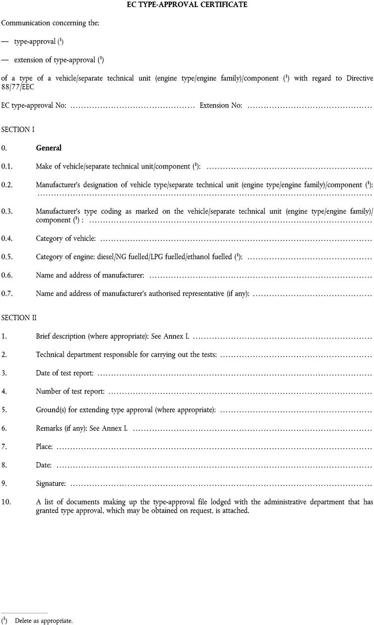
[F1Appendix 1] to EC type-approval certificate No … concerning the type approval of a vehicle/separate technical unit/component(25)
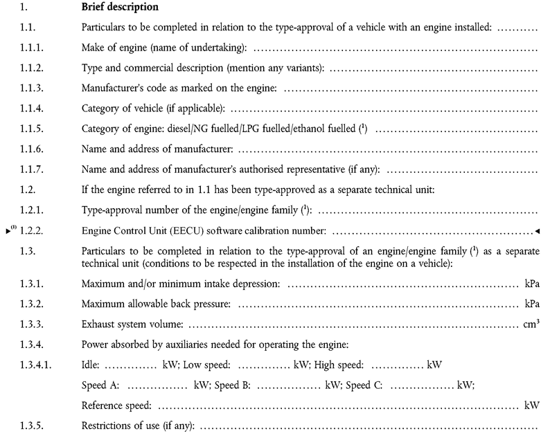
[F11.4. Emission levels of the engine/parent engine (26) : U.K.
1.4.1. ESC test: U.K.
Deterioration factor (DF): calculated/fixed (26)
Specify the DF values and the emissions on the ESC test in the table below:
| ESC test | ||||
|---|---|---|---|---|
| DF: | CO | THC | NO x | PT |
| Emissions | CO (g/kWh) | THC (g/kWh) | NO x (g/kWh) | PT (g/kWh) |
| Measured: | ||||
| Calculated with DF: | ||||
1.4.2. ELR test: U.K.
smoke value: … m –1
1.4.3. ETC test: U.K.
Deterioration factor (DF): calculated/fixed (26)
[F2Appendix 2 OBD RELATED INFORMATION
As noted in Appendix 5 of Annex II to this Directive, the information in this appendix is provided by the vehicle manufacturer for the purposes of enabling the manufacture of OBD-compatible replacement or service parts and diagnostic tools and test equipment. Such information need not be supplied by the vehicle manufacturer if it is covered by intellectual property rights or constitutes specific know-how of the manufacturer or the OEM supplier(s).
Upon request, this appendix will be made available to any interested component, diagnostic tools or test equipment manufacturer, on a non-discriminatory basis.
In compliance with the provisions of section 1.3.3 of Appendix 5 to Annex II, the information required by this section shall be identical to that provided in that Appendix.
1.
A description of the type and number of the pre-conditioning cycles used for the original type approval of the vehicle.
2.
A description of the type of the OBD demonstration cycle used for the original type approval of the vehicle for the component monitored by the OBD system.
3.
A comprehensive document describing all sensed components with the strategy for fault detection and MI activation (fixed number of driving cycles or statistical method), including a list of relevant secondary sensed parameters for each component monitored by the OBD system. A list of all OBD output codes and format used (with an explanation of each) associated with individual emission related powertrain components and individual non-emission related components, where monitoring of the component is used to determine MI activation.]
ANNEX VIIU.K.EXAMPLE OF CALCULATION PROCEDURE
1.ESC TESTU.K.
1.1.Gaseous emissionsU.K.
The measurement data for the calculation of the individual mode results are shown below. In this example, CO and NOx are measured on a dry basis, HC on a wet basis. The HC concentration is given in propane equivalent (C3) and has to be multiplied by 3 to result in the C1 equivalent. The calculation procedure is identical for the other modes.
| P(kW) | Ta(K) | Ha(g/kg) | GEXH(kg) | GAIRW(kg) | GFUEL(kg) | HC(ppm) | CO(ppm) | NOx(ppm) |
|---|---|---|---|---|---|---|---|---|
| 82,9 | 294,8 | 7,81 | 563,38 | 545,29 | 18,09 | 6,3 | 41,2 | 495 |
Calculation of the dry to wet correction factor KW,r (Annex III, Appendix 1, Section 4.2):U.K.


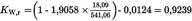
Calculation of the wet concentrations:U.K.


Calculation of the NOx humidity correction factor KH,D (Annex III, Appendix 1, Section 4.3):U.K.


Calculation of the emission mass flow rates (Annex III, Appendix 1, Section 4.4):U.K.


Calculation of the specific emissions (Annex III, Appendix 1, Section 4.5):U.K.
The following example calculation is given for CO; the calculation procedure is identical for the other components.
The emission mass flow rates of the individual modes are multiplied by the respective weighting factors, as indicated in Annex III, Appendix 1, Section 2.7.1, and summed up to result in the mean emission mass flow rate over the cycle:

The engine power of the individual modes is multiplied by the respective weighting factors, as indicated in Annex III, Appendix 1, Section 2.7.1, and summed up to result in the mean cycle power:


Calculation of the specific NOx emission of the random point (Annex III, Appendix 1, Section 4.6.1):U.K.
Assume the following values have been determined on the random point:
nZ
=
1 600 min-1
MZ
=
495 Nm
NOx mass,Z
=
487,9 g/h (calculated according to the previous formulae)
P(n)Z
=
83 kW
NOx,Z
=
487,9/83 = 5,878 g/kWh
Determination of the emission value from the test cycle (Annex III, Appendix 1, Section 4.6.2):U.K.
Assume the values of the four enveloping modes on the ESC to be as follows:
| nRT | nSU | ER | ES | ET | EU | MR | MS | MT | MU |
|---|---|---|---|---|---|---|---|---|---|
| 1 368 | 1 785 | 5,943 | 5,565 | 5,889 | 4,973 | 515 | 460 | 681 | 610 |


Comparison of the NOx emission values (Annex III, Appendix 1, Section 4.6.3):U.K.

1.2.Particulate emissionsU.K.
Particulate measurement is based on the principle of sampling the particulates over the complete cycle, but determining the sample and flow rates (MSAM and GEDF) during the individual modes. The calculation of GEDF depends on the system used. In the following examples, a system with CO2 measurement and carbon balance method and a system with flow measurement are used. When using a full flow dilution system, GEDF is directly measured by the CVS equipment.
Calculation of GEDF (Annex III, Appendix 1, Sections 5.2.3 and 5.2.4):U.K.
Assume the following measurement data of mode 4. The calculation procedure is identical for the other modes.
| GEXH(kg/h) | GFUEL(kg/h) | GDILW(kg/h) | GTOTW(kg/h) | CO2D(%) | CO2A(%) |
|---|---|---|---|---|---|
| 334,02 | 10,76 | 5,4435 | 6,0 | 0,657 | 0,04 |


Calculation of the mass flow rate (Annex III, Appendix 1, Section 5.4):U.K.
The GEDFW flow rates of the individual modes are multiplied by the respective weighting factors, as indicated in Annex III, Appendix 1, Section 2.7.1, and summed up to result in the mean GEDF over the cycle. The total sample rate MSAM is summed up from the sample rates of the individual modes.


Assume the particulate mass on the filters to be 2,5 mg, then

Background correction (optional)U.K.
Assume one background measurement with the following values. The calculation of the dilution factor DF is identical to Section 3.1 of this Annex and not shown here.


Calculation of the specific emission (Annex III, Appendix 1, Section 5.5):U.K.


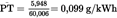

Calculation of the specific weighting factor (Annex III, Appendix 1, Section 5.6):U.K.
Assume the values calculated for mode 4 above, then

This value is within the required value of 0,10 ± 0,003.
2.ELR TESTU.K.
Since Bessel filtering is a completely new averaging procedure in European exhaust legislation, an explanation of the Bessel filter, an example of the design of a Bessel algorithm, and an example of the calculation of the final smoke value is given below. The constants of the Bessel algorithm only depend on the design of the opacimeter and the sampling rate of the data acquisition system. It is recommended that the opacimeter manufacturer provide the final Bessel filter constants for different sampling rates and that the customer use these constants for designing the Bessel algorithm and for calculating the smoke values.
2.1.General remarks on the Bessel filterU.K.
Due to high frequency distortions, the raw opacity signal usually shows a highly scattered trace. To remove these high frequency distortions a Bessel filter is required for the ELR-test. The Bessel filter itself is a recursive, second-order low-pass filter which guarantees the fastest signal rise without overshoot.
Assuming a real time raw exhaust plume in the exhaust tube, each opacimeter shows a delayed and differently measured opacity trace. The delay and the magnitude of the measured opacity trace is primarily dependent on the geometry of the measuring chamber of the opacimeter, including the exhaust sample lines, and on the time needed for processing the signal in the electronics of the opacimeter. The values that characterise these two effects are called the physical and the electrical response time which represent an individual filter for each type of opacimeter.
The goal of applying a Bessel filter is to guarantee a uniform overall filter characteristic of the whole opacimeter system, consisting of:
physical response time of the opacimeter (tp),
electrical response time of the opacimeter (te),
filter response time of the applied Bessel filter (tF).
The resulting overall response time of the system tAver is given by:

and must be equal for all kinds of opacimeters in order to give the same smoke value. Therefore, a Bessel filter has to be created in such a way, that the filter response time (tF) together with the physical (tp) and electrical response time (te) of the individual opacimeter must result in the required overall response time (tAver). Since tp and te are given values for each individual opacimeter, and tAver is defined to be 1,0 s in this Directive, tF can be calculated as follows:

By definition, the filter response time tF is the rise time of a filtered output signal between 10 % and 90 % on a step input signal. Therefore the cut-off frequency of the Bessel filter has to be iterated in such a way, that the response time of the Bessel filter fits into the required rise time.

In Figure a, the traces of a step input signal and Bessel filtered output signal as well as the response time of the Bessel filter (tF) are shown.
Designing the final Bessel filter algorithm is a multi step process which requires several iteration cycles. The scheme of the iteration procedure is presented below.
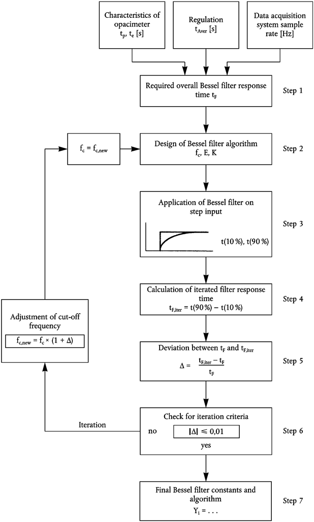
2.2.Calculation of the Bessel algorithmU.K.
In this example a Bessel algorithm is designed in several steps according to the above iteration procedure which is based upon Annex III, Appendix 1, Section 6.1.
For the opacimeter and the data acquisition system, the following characteristics are assumed:
physical response time tp 0,15 s
electrical response time te 0,05 s
overall response time tAver 1,00 s (by definition in this Directive)
sampling rate 150 Hz
Step 1Required Bessel filter response time tF:U.K.

Step 2Estimation of cut-off frequency and calculation of Bessel constants E, K for first iteration:U.K.

Δt
=
1/150 = 0,006667 s


This gives the Bessel algorithm:

where Si represents the values of the step input signal (either ‘0’ or ‘1’) and Yi represents the filtered values of the output signal.
Step 3Application of Bessel filter on step input:U.K.
The Bessel filter response time tF is defined as the rise time of the filtered output signal between 10 % and 90 % on a step input signal. For determining the times of 10 % (t10) and 90 % (t90) of the output signal, a Bessel filter has to be applied to a step input using the above values of fc, E and K.
The index numbers, the time and the values of a step input signal and the resulting values of the filtered output signal for the first and the second iteration are shown in Table B. The points adjacent to t10 and t90 are marked in bold numbers.
In Table B, first iteration, the 10 % value occurs between index number 30 and 31 and the 90 % value occurs between index number 191 and 192. For the calculation of tF,iter the exact t10 and t90 values are determined by linear interpolation between the adjacent measuring points, as follows:


where outupper and outlower, respectively, are the adjacent points of the Bessel filtered output signal, and tlower is the time of the adjacent time point, as indicated in Table B.


Step 4Filter response time of first iteration cycle:U.K.

Step 5Deviation between required and obtained filter response time of first iteration cycle:U.K.

Step 6Checking the iteration criteria:U.K.
|Δ| ≤ 0,01 is required. Since 0,081641 > 0,01, the iteration criteria is not met and a further iteration cycle has to be started. For this iteration cycle, a new cut-off frequency is calculated from fc and Δ as follows:

This new cut-off frequency is used in the second iteration cycle, starting at step 2 again. The iteration has to be repeated until the iteration criteria is met. The resulting values of the first and second iteration are summarised in Table A.
Table A
Values of the first and second iteration
| Parameter | 1. Iteration | 2. Iteration | |
|---|---|---|---|
| fc | (Hz) | 0,318152 | 0,344126 |
| E | (-) | 7,07948 E-5 | 8,272777 E-5 |
| K | (-) | 0,970783 | 0,96841 |
| t10 | (s) | 0,200945 | 0,185523 |
| t90 | (s) | 1,276147 | 1,179562 |
| tF,iter | (s) | 1,075202 | 0,994039 |
| Δ | (-) | 0,081641 | 0,006657 |
| fc,new | (Hz) | 0,344126 | 0,346417 |
Step 7Final Bessel algorithm:U.K.
As soon as the iteration criteria has been met, the final Bessel filter constants and the final Bessel algorithm are calculated according to step 2. In this example, the iteration criteria has been met after the second iteration (Δ = 0,006657 ≤ 0,01). The final algorithm is then used for determining the averaged smoke values (see next Section 2.3).

Table B
Values of step input signal and Bessel filtered output signal for the first and second iteration cycle
| Index i[-] | Time[s] | Step input signal Si[-] | Filtered output signal Yi[-] | |
|---|---|---|---|---|
| 1. Iteration | 2. Iteration | |||
| - 2 | - 0,013333 | 0 | 0,0 | 0,0 |
| - 1 | - 0,006667 | 0 | 0,0 | 0,0 |
| 0 | 0,0 | 1 | 0,000071 | 0,000083 |
| 1 | 0,006667 | 1 | 0,000352 | 0,000411 |
| 2 | 0,013333 | 1 | 0,000908 | 0,00106 |
| 3 | 0,02 | 1 | 0,001731 | 0,002019 |
| 4 | 0,026667 | 1 | 0,002813 | 0,003278 |
| 5 | 0,033333 | 1 | 0,004145 | 0,004828 |
| ~ | ~ | ~ | ~ | ~ |
| 24 | 0,16 | 1 | 0,067877 | 0,077876 |
| 25 | 0,166667 | 1 | 0,072816 | 0,083476 |
| 26 | 0,173333 | 1 | 0,077874 | 0,089205 |
| 27 | 0,18 | 1 | 0,083047 | 0,095056 |
| 28 | 0,186667 | 1 | 0,088331 | 0,101024 |
| 29 | 0,193333 | 1 | 0,093719 | 0,107102 |
| 30 | 0,2 | 1 | 0,099208 | 0,113286 |
| 31 | 0,206667 | 1 | 0,104794 | 0,11957 |
| 32 | 0,213333 | 1 | 0,110471 | 0,125949 |
| 33 | 0,22 | 1 | 0,116236 | 0,132418 |
| 34 | 0,226667 | 1 | 0,122085 | 0,138972 |
| 35 | 0,233333 | 1 | 0,128013 | 0,145605 |
| 36 | 0,24 | 1 | 0,134016 | 0,152314 |
| 37 | 0,246667 | 1 | 0,140091 | 0,159094 |
| ~ | ~ | ~ | ~ | ~ |
| 175 | 1,166667 | 1 | 0,862416 | 0,895701 |
| 176 | 1,173333 | 1 | 0,864968 | 0,897941 |
| 177 | 1,18 | 1 | 0,867484 | 0,900145 |
| 178 | 1,186667 | 1 | 0,869964 | 0,902312 |
| 179 | 1,193333 | 1 | 0,87241 | 0,904445 |
| 180 | 1,2 | 1 | 0,874821 | 0,906542 |
| 181 | 1,206667 | 1 | 0,877197 | 0,908605 |
| 182 | 1,213333 | 1 | 0,87954 | 0,910633 |
| 183 | 1,22 | 1 | 0,881849 | 0,912628 |
| 184 | 1,226667 | 1 | 0,884125 | 0,914589 |
| 185 | 1,233333 | 1 | 0,886367 | 0,916517 |
| 186 | 1,24 | 1 | 0,888577 | 0,918412 |
| 187 | 1,246667 | 1 | 0,890755 | 0,920276 |
| 188 | 1,253333 | 1 | 0,8929 | 0,922107 |
| 189 | 1,26 | 1 | 0,895014 | 0,923907 |
| 190 | 1,266667 | 1 | 0,897096 | 0,925676 |
| 191 | 1,273333 | 1 | 0,899147 | 0,927414 |
| 192 | 1,28 | 1 | 0,901168 | 0,929121 |
| 193 | 1,286667 | 1 | 0,903158 | 0,930799 |
| 194 | 1,293333 | 1 | 0,905117 | 0,932448 |
| 195 | 1,3 | 1 | 0,907047 | 0,934067 |
| ~ | ~ | ~ | ~ | ~ |
2.3.Calculation of the smoke valuesU.K.
In the scheme below the general procedure of determining the final smoke value is presented.

In Figure b, the traces of the measured raw opacity signal, and of the unfiltered and filtered light absorption coefficients (k-value) of the first load step of an ELR-Test are shown, and the maximum value Ymax1,A (peak) of the filtered k trace is indicated. Correspondingly, Table C contains the numerical values of index i, time (sampling rate of 150 Hz), raw opacity, unfiltered k and filtered k. Filtering was conducted using the constants of the Bessel algorithm designed in Section 2.2 of this Annex. Due to the large amount of data, only those sections of the smoke trace around the beginning and the peak are tabled.

The peak value (i = 272) is calculated assuming the following data of Table C. All other individual smoke values are calculated in the same way. For starting the algorithm, S-1, S-2, Y-1 and Y-2 are set to zero.
| LA (m) | 0,43 |
| Index i | 272 |
| N ( %) | 16,783 |
| S271 (m-1) | 0,427392 |
| S270 (m-1) | 0,427532 |
| Y271 (m-1) | 0,542383 |
| Y270 (m-1) | 0,542337 |
Calculation of the k-value (Annex III, Appendix 1, Section 6.3.1):U.K.

This value corresponds to S272 in the following equation.
Calculation of Bessel averaged smoke (Annex III, Appendix 1, Section 6.3.2):U.K.
In the following equation, the Bessel constants of the previous Section 2.2 are used. The actual unfiltered k-value, as calculated above, corresponds to S272 (Si). S271 (Si-1) and S270 (Si-2) are the two preceding unfiltered k-values, Y271 (Yi-1) and Y270 (Yi-2) are the two preceding filtered k-values.


This value corresponds to Ymax1,A in the following equation.
Calculation of the final smoke value (Annex III, Appendix 1, Section 6.3.3):U.K.
From each smoke trace, the maximum filtered k-value is taken for the further calculation.
Assume the following values
| Speed | Ymax (m-1) | ||
|---|---|---|---|
| Cycle 1 | Cycle 2 | Cycle 3 | |
| A | 0,5424 | 0,5435 | 0,5587 |
| B | 0,5596 | 0,54 | 0,5389 |
| C | 0,4912 | 0,5207 | 0,5177 |


Cycle validation (Annex III, Appendix 1, Section 3.4)U.K.
Before calculating SV, the cycle must be validated by calculating the relative standard deviations of the smoke of the three cycles for each speed.
| Speed | Mean SV(m-1) | Absolute standard deviation(m-1) | Relative standard deviation(%) |
|---|---|---|---|
| A | 0,5482 | 0,0091 | 1,7 |
| B | 0,5462 | 0,0116 | 2,1 |
| C | 0,5099 | 0,0162 | 3,2 |
In this example, the validation criteria of 15 % are met for each speed.
Table C
Values of opacity N, unfiltered and filtered k-value at beginning of load step
| Index i[-] | Time[s] | Opacity N[%] | Unfiltered k-value[m-1] | Filtered k-value[m-1] |
|---|---|---|---|---|
| - 2 | 0,0 | 0,0 | 0,0 | 0,0 |
| - 1 | 0,0 | 0,0 | 0,0 | 0,0 |
| 0 | 0,0 | 0,0 | 0,0 | 0,0 |
| 1 | 0,006667 | 0,02 | 0,000465 | 0,0 |
| 2 | 0,013333 | 0,02 | 0,000465 | 0,0 |
| 3 | 0,02 | 0,02 | 0,000465 | 0,0 |
| 4 | 0,026667 | 0,02 | 0,000465 | 0,000001 |
| 5 | 0,033333 | 0,02 | 0,000465 | 0,000002 |
| 6 | 0,04 | 0,02 | 0,000465 | 0,000002 |
| 7 | 0,046667 | 0,02 | 0,000465 | 0,000003 |
| 8 | 0,053333 | 0,02 | 0,000465 | 0,000004 |
| 9 | 0,06 | 0,02 | 0,000465 | 0,000005 |
| 10 | 0,066667 | 0,02 | 0,000465 | 0,000006 |
| 11 | 0,073333 | 0,02 | 0,000465 | 0,000008 |
| 12 | 0,08 | 0,02 | 0,000465 | 0,000009 |
| 13 | 0,086667 | 0,02 | 0,000465 | 0,000011 |
| 14 | 0,093333 | 0,02 | 0,000465 | 0,000012 |
| 15 | 0,1 | 0,192 | 0,004469 | 0,000014 |
| 16 | 0,106667 | 0,212 | 0,004935 | 0,000018 |
| 17 | 0,113333 | 0,212 | 0,004935 | 0,000022 |
| 18 | 0,12 | 0,212 | 0,004935 | 0,000028 |
| 19 | 0,126667 | 0,343 | 0,00799 | 0,000036 |
| 20 | 0,133333 | 0,566 | 0,0132 | 0,000047 |
| 21 | 0,14 | 0,889 | 0,020767 | 0,000061 |
| 22 | 0,146667 | 0,929 | 0,021706 | 0,000082 |
| 23 | 0,153333 | 0,929 | 0,021706 | 0,000109 |
| 24 | 0,16 | 1,263 | 0,029559 | 0,000143 |
| 25 | 0,166667 | 1,455 | 0,034086 | 0,000185 |
| 26 | 0,173333 | 1,697 | 0,039804 | 0,000237 |
| 27 | 0,18 | 2,03 | 0,047695 | 0,000301 |
| 28 | 0,186667 | 2,081 | 0,048906 | 0,000378 |
| 29 | 0,193333 | 2,081 | 0,048906 | 0,000469 |
| 30 | 0,2 | 2,424 | 0,057067 | 0,000573 |
| 31 | 0,206667 | 2,475 | 0,058282 | 0,000693 |
| 32 | 0,213333 | 2,475 | 0,058282 | 0,000827 |
| 33 | 0,22 | 2,808 | 0,066237 | 0,000977 |
| 34 | 0,226667 | 3,01 | 0,071075 | 0,001144 |
| 35 | 0,233333 | 3,253 | 0,076909 | 0,001328 |
| 36 | 0,24 | 3,606 | 0,08541 | 0,001533 |
| 37 | 0,246667 | 3,96 | 0,093966 | 0,001758 |
| 38 | 0,253333 | 4,455 | 0,105983 | 0,002007 |
| 39 | 0,26 | 4,818 | 0,114836 | 0,002283 |
| 40 | 0,266667 | 5,02 | 0,119776 | 0,002587 |
Values of opacity N, unfiltered and filtered k-value around Ymax1,A (≡ peak value, indicated in bold number)
| Index i[-] | Time[s] | Opacity N[%] | Unfiltered k-value[m-1] | Filtered k-value[m-1] |
|---|---|---|---|---|
| 259 | 1,726667 | 17,182 | 0,438429 | 0,538856 |
| 260 | 1,733333 | 16,949 | 0,431896 | 0,539423 |
| 261 | 1,74 | 16,788 | 0,427392 | 0,539936 |
| 262 | 1,746667 | 16,798 | 0,427671 | 0,540396 |
| 263 | 1,753333 | 16,788 | 0,427392 | 0,540805 |
| 264 | 1,76 | 16,798 | 0,427671 | 0,541163 |
| 265 | 1,766667 | 16,798 | 0,427671 | 0,541473 |
| 266 | 1,773333 | 16,788 | 0,427392 | 0,541735 |
| 267 | 1,78 | 16,788 | 0,427392 | 0,541951 |
| 268 | 1,786667 | 16,798 | 0,427671 | 0,542123 |
| 269 | 1,793333 | 16,798 | 0,427671 | 0,542251 |
| 270 | 1,8 | 16,793 | 0,427532 | 0,542337 |
| 271 | 1,806667 | 16,788 | 0,427392 | 0,542383 |
| 272 | 1,813333 | 16,783 | 0,427252 | 0,542389 |
| 273 | 1,82 | 16,78 | 0,427168 | 0,542357 |
| 274 | 1,826667 | 16,798 | 0,427671 | 0,542288 |
| 275 | 1,833333 | 16,778 | 0,427112 | 0,542183 |
| 276 | 1,84 | 16,808 | 0,427951 | 0,542043 |
| 277 | 1,846667 | 16,768 | 0,426833 | 0,54187 |
| 278 | 1,853333 | 16,01 | 0,40575 | 0,541662 |
| 279 | 1,86 | 16,01 | 0,40575 | 0,541418 |
| 280 | 1,866667 | 16,0 | 0,405473 | 0,541136 |
| 281 | 1,873333 | 16,01 | 0,40575 | 0,540819 |
| 282 | 1,88 | 16,0 | 0,405473 | 0,540466 |
| 283 | 1,886667 | 16,01 | 0,40575 | 0,54008 |
| 284 | 1,893333 | 16,394 | 0,416406 | 0,539663 |
| 285 | 1,9 | 16,394 | 0,416406 | 0,539216 |
| 286 | 1,906667 | 16,404 | 0,416685 | 0,538744 |
| 287 | 1,913333 | 16,394 | 0,416406 | 0,538245 |
| 288 | 1,92 | 16,394 | 0,416406 | 0,537722 |
| 289 | 1,926667 | 16,384 | 0,416128 | 0,537175 |
| 290 | 1,933333 | 16,01 | 0,40575 | 0,536604 |
| 291 | 1,94 | 16,01 | 0,40575 | 0,536009 |
| 292 | 1,946667 | 16,0 | 0,405473 | 0,535389 |
| 293 | 1,953333 | 16,01 | 0,40575 | 0,534745 |
| 294 | 1,96 | 16,212 | 0,411349 | 0,534079 |
| 295 | 1,966667 | 16,394 | 0,416406 | 0,533394 |
| 296 | 1,973333 | 16,394 | 0,416406 | 0,532691 |
| 297 | 1,98 | 16,192 | 0,410794 | 0,531971 |
| 298 | 1,986667 | 16,0 | 0,405473 | 0,531233 |
| 299 | 1,993333 | 16,0 | 0,405473 | 0,530477 |
| 300 | 2,0 | 16,0 | 0,405473 | 0,529704 |
3.ETC TESTU.K.
3.1.Gaseous emissions (diesel engine)U.K.
Assume the following test results for a PDP-CVS system
| V0 (m3/rev) | 0,1776 |
| Np (rev) | 23 073 |
| pB (kPa) | 98,0 |
| p1 (kPa) | 2,3 |
| T (K) | 322,5 |
| Ha (g/kg) | 12,8 |
| NOx conce (ppm) | 53,7 |
| NOx concd (ppm) | 0,4 |
| COconce (ppm) | 38,9 |
| COconcd (ppm) | 1,0 |
| HCconce (ppm) | 9,0 |
| HCconcd (ppm) | 3,02 |
| CO2,conce (%) | 0,723 |
| Wact (kWh) | 62,72 |
Calculation of the diluted exhaust gas flow (Annex III, Appendix 2, Section 4.1):U.K.

Calculation of the NOx correction factor (Annex III, Appendix 2, Section 4.2):U.K.

Calculation of the background corrected concentrations (Annex III, Appendix 2, Section 4.3.1.1):U.K.
Assuming a diesel fuel of the composition C1H1,8
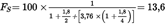


Calculation of the emissions mass flow (Annex III, Appendix 2, Section 4.3.1):U.K.


Calculation of the specific emissions (Annex III, Appendix 2, Section 4.4):U.K.


3.2.Particulate emissions (diesel engine)U.K.
Assume the following test results for a PDP-CVS system with double dilution
| MTOTW (kg) | 4 237,2 |
| Mf,p (mg) | 3,03 |
| Mf,b (mg) | 0,044 |
| MTOT (kg) | 2,159 |
| MSEC (kg) | 0,909 |
| Md (mg) | 0,341 |
| MDIL (kg) | 1,245 |
| DF | 18,69 |
| Wact (kWh) | 62,72 |
Calculation of the mass emission (Annex III, Appendix 2, Section 5.1):U.K.


Calculation of the background corrected mass emission (Annex III, Appendix 2, Section 5.1):U.K.

Calculation of the specific emission (Annex III, Appendix 2, Section 5.2):U.K.


3.3.Gaseous emissions (CNG engine)U.K.
Assume the following test results for a PDP-CVS system with double dilution
| MTOTW (kg) | 4 237,2 |
| Ha (g/kg) | 12,8 |
| NOx conce (ppm) | 17,2 |
| NOx concd (ppm) | 0,4 |
| COconce (ppm) | 44,3 |
| COconcd (ppm) | 1,0 |
| HCconce (ppm) | 27,0 |
| HCconcd (ppm) | 3,02 |
| CH4 conce (ppm) | 18,0 |
| CH4 concd (ppm) | 1,7 |
| CO2,conce ( %) | 0,723 |
| Wact (kWh) | 62,72 |
Calculation of the NOx, correction factor (Annex III, Appendix 2, Section 4.2):U.K.

Calculation of the NMHC concentration (Annex III, Appendix 2, Section 4.3.1):U.K.


Calculation of the background corrected concentrations (Annex III, Appendix 2, Section 4.3.1.1):U.K.
Assuming a G20 reference fuel (100 % methane) of the composition C1H4:


For NMHC, the background concentration is the difference between HCconcd and CH4concd U.K.


Calculation of the emissions mass flow (Annex III, Appendix 2, Section 4.3.1):U.K.


Calculation of the specific emissions (Annex III, Appendix 2, Section 4.4):U.K.


4.λ-SHIFT FACTOR (Sλ)U.K.
4.1.Calculation of the λ-shift factor (Sλ)(27) U.K.

where:
Sλ
=
λ-shift factor;
inert %
=
% by volume of inert gases in the fuel (i.e. N2, CO2, He, etc.);
O2 *
=
% by volume of original oxygen in the fuel;


where:
CH4
=
% by volume of methane in the fuel;
C2
=
% by volume of all C2 hydrocarbons (e.g. C2H6, C2H4, etc.) in the fuel;
C3
=
% by volume of all C3 hydrocarbons (e.g. C3H8, C3H6, etc.) in the fuel;
C4
=
% by volume of all C4 hydrocarbons (e.g. C4H10, C4H8, etc.) in the fuel
C5
=
% by volume of all C5 hydrocarbons (e.g. C5H12, C5H10, etc.) in the fuel;
diluent
=
% by volume of dilution gases in the fuel (i.e. O2 *, N2, CO2, He etc.).
4.2.Examples for the calculation of the λ-shift factor Sλ U.K.
Example 1: G25: CH4 = 86 %, N2 = 14 % (by volume)U.K.

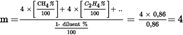
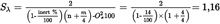
Example 2: GR: CH4 = 87 %, C2H6 = 13 % (by vol)U.K.

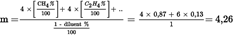

Example 3: USA: CH4 = 89 %, C2H6 = 4,5 %, C3H8 = 2,3 %, C6H14 = 0,2 %, O2 = 0,6 %, N2 = 4 %U.K.


ANNEX VIIIU.K.SPECIFIC TECHNICAL REQUIREMENTS RELATING TO ETHANOL-FUELLED DIESEL ENGINES
In the case of ethanol-fuelled diesel engines, the following specific modifications to the appropriate paragraphs, equations and factors will apply to the test procedures defined in Annex III to this Directive.
IN ANNEX III, APPENDIX 1:U.K.
4.2.Dry/wet correctionU.K.
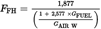
4.3.NOx correction for humidity and temperatureU.K.

with,
A
=
0,181 GFUEL/GAIRD - 0,0266
B
=
– 0,123 GFUEL/GAIRD + 0,00954
Ta
=
temperature of the air, K
Ha
=
humidity of the intake air, g water per kg dry air
4.4.Calculation of the emission mass flow ratesU.K.
The emission mass flow rates (g/h) for each mode shall be calculated as follows, assuming the exhaust gas density to be 1,272 kg/m3 at 273 K (0 °C) and 101,3 kPa:

[(1)]

[(2)]

[(3)]
where
NOx conc, COconc, HCconc (28) are the average concentrations (ppm) in the raw exhaust gas, as determined in Section 4.1.
If, optionally, the gaseous emissions are determined with a full flow dilution system, the following formulae shall be applied:

[(1)]

[(2)]

[(3)]
where
NOx conc, COconc, HCconc (28) are the average background corrected concentrations (ppm) of each mode in the diluted exhaust gas, as determined in Annex III, Appendix 2, Section 4.3.1.1.
IN ANNEX III, APPENDIX 2:U.K.
Sections 3.1, 3.4, 3.8.3 and 5 of Appendix 2 do not apply solely to diesel engines. They also apply to ethanol-fuelled diesel engines.
4.2.The conditions for the test should be arranged so that the air temperature and the humidity measured at the engine intake is set to standard conditions during the test run. The standard should be 6 ± 0,5 g water per kg dry air at a temperature interval of 298 ± 3 K. Within these limits no further NOx correction should be made. The test is void if these conditions are not met.U.K.
4.3.Calculation of the emission mass flowU.K.
4.3.1Systems with constant mass flowU.K.
For systems with heat exchanger, the mass of the pollutants (g/test) shall be determined from the following equations:

[(1)]

[(2)]

[(3)]
where,
NOx conc, COconc, HCconc (29), NMHCconc
=
average background corrected concentrations over the cycle from integration (mandatory for NOx and HC) or bag measurement, ppm;
MTOTW
=
total mass of diluted exhaust gas over the cycle as determined in Section 4.1, kg.
4.3.1.1.Determination of the background corrected concentrationsU.K.
The average background concentration of the gaseous pollutants in the dilution air shall be subtracted from measured concentrations to get the net concentrations of the pollutants. The average values of the background concentrations can be determined by the sample bag method or by continuous measurement with integration. The following formula shall be used.

where,
conc
=
concentration of the respective pollutant in the diluted exhaust gas, corrected by the amount of the respective pollutant contained in the dilution air, ppm;
conce
=
concentration of the respective pollutant measured in the diluted exhaust gas, ppm;
concd
=
concentration of the respective pollutant measured in the dilution air, ppm;
DF
=
dilution factor.
The dilution factor shall be calculated as follows:

where,
CO2conce
=
concentration of CO2 in the diluted exhaust gas, % vol
HCconce
=
concentration of HC in the diluted exhaust gas, ppm C1
COconce
=
concentration of CO in the diluted exhaust gas, ppm
FS
=
stoichiometric factor
Concentrations measured on dry basis shall be converted to a wet basis in accordance with Annex III, Appendix 1, Section 4.2.
The stoichiometric factor shall, for the general fuel composition CHαOβNγ, be calculated as follows:
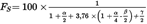
Alternatively, if the fuel composition is not known, the following stoichiometric factors may be used:
FS (Ethanol) = 12,3
4.3.2.Systems with flow compensationU.K.
For systems without heat exchanger, the mass of the pollutants (g/test) shall be determined by calculating the instantaneous mass emissions and integrating the instantaneous values over the cycle. Also, the background correction shall be applied directly to the instantaneous concentration value. The following formulae shall be applied:

[(1)]

[(2)]

[(3)]
where,
conce
=
concentration of the respective pollutant measured in the diluted exhaust gas, ppm;
concd
=
concentration of the respective pollutant measured in the dilution air, ppm;
MTOTW,i
=
instantaneous mass of the diluted exhaust gas (see Section 4.1), kg;
MTOTW
=
total mass of diluted exhaust gas over the cycle (see Section 4.1), kg;
DF
=
dilution factor as dertermined in Section 4.3.1.1.
4.4.Calculation of the specific emissionsU.K.
The emissions (g/kWh) shall be calculated for all individual components in the following way:


where,
Wact
=
actual cycle work as determined in Section 3.9.2, kWh.
ANNEX IXU.K.TIME-LIMITS FOR THE TRANSPOSITION OF THE REPEALED DIRECTIVES INTO NATIONAL LAWSReferred to in Article 10
Part A
Repealed Directives
| Directives | Official Journal |
|---|---|
| Directive 88/77/EEC | L 36, 9.2.1988, p. 33. |
| Directive 91/542/EEC | L 295, 25.10.1991, p. 1. |
| Directive 96/1/EC | L 40, 17.2.1996, p. 1. |
| Directive 1999/96/EC | L 44, 16.2.2000, p. 1. |
| Directive 2001/27/EC | L 107, 18.4.2001, p. 10. |
Part B
Time limits for transposition into national laws
| Directive | Time-limits for transposition | Date of application |
|---|---|---|
| Directive 88/77/EEC | 1 July 1988 | |
| Directive 91/542/EEC | 1 January 1992 | |
| Directive 96/1/EC | 1 July 1996 | |
| Directive 1999/96/EC | 1 July 2000 | |
| Directive 2001/27/EC | 1 October 2001 | 1 October 2001 |
ANNEX XU.K.CORRELATION TABLE(Referred to in the second paragraph of Article 10)
| Directive 88/77/EEC | Directive 91/542/EEC | Directive 1999/96/EC | Directive 2001/27/EC | This Directive |
|---|---|---|---|---|
| Article 1 | — | — | Article 1 | |
| Article 2(1) | Article 2(1) | Article 2(1) | Article 2(1) | Article 2(4) |
| Article 2(2) | Article 2(2) | Article 2(2) | Article 2(2) | Article 2(1) |
| — | Article 2(3) | — | — | — |
| Article 2(3) | — | — | — | — |
| Article 2(4) | Article 2(4) | Article 2(3) | Article 2(3) | Article 2(2) |
| — | — | — | Article 2(4) | Article 2(3) |
| — | — | — | Article 2(5) | — |
| — | — | Article 2(4) | — | Article 2(5) |
| — | — | Article 2(5) | — | Article 2(6) |
| — | — | Article 2(6) | — | Article 2(7) |
| — | — | Article 2(7) | — | Article 2(8) |
| — | — | Article 2(8) | — | Article 2(9) |
| Article 3 | — | — | — | — |
| — | — | Article 5 and 6 | — | Article 3 |
| — | — | Article 4 | — | Article 4 |
| — | Article 3(1) | Article 3(1) | — | Article 6(1) |
| — | Article 3(1)(a) | Article 3(1)(a) | — | Article 6(2) |
| — | Article 3(1)(b) | Article 3(1)(b) | — | Article 6(3) |
| — | Article 3(2) | Article 3(2) | — | Article 6(4) |
| — | Article 3(3) | Article 3(3) | — | Article 6(5) |
| Article 4 | — | — | — | Article 7 |
| Article 6 | Article 5 and 6 | Article 7 | — | Article 8 |
| Article 5 | Article 4 | Article 8 | Article 3 | Article 9 |
| — | — | — | — | Article 10 |
| — | — | Article 9 | Article 4 | Article 11 |
| Article 7 | Article 7 | Article 10 | Article 5 | Article 12 |
| Annexes I to VII | — | — | — | Annexes I to VII |
| — | — | — | Annex VIII | Annex VIII |
| — | — | — | — | Annex IX |
| — | — | — | — | Annex X |
(2)
Opinion of the European Parliament of 9 March 2004 (OJ C 102 E, 28.4.2004, p. 272) and Council Decision of 19 September 2005.
(3)
OJ L 36, 9.2.1988, p. 33. Directive as last amended by the 2003 Act of Accession.
(4)
OJ L 42, 23.2.1970, p. 1. Directive as last amended by Commission Directive 2005/49/EC (OJ L 194, 26.7.2005, p. 12).
(8)
OJ L 76, 6.4.1970, p. 1. Directive as last amended by Commission Directive 2003/76/EC (OJ L 206, 15.8.2003, p. 29).
(10)
[F1 OJ L 76, 6.4.1970, p. 1 . Directive as last amended by Commission Directive 2003/76/EC ( OJ L 206, 15.8.2003, p. 29 ).]
(11)
(12)
Article 4(1) of this Directive provides for the monitoring for major functional failure instead of monitoring for the degradation or the loss of catalytic/filtering efficiency of an exhaust aftertreatment system. Examples of major functional failure are given in sections 3.2.3.2 and 3.2.3.3 of Annex IV to Directive 2005/78/EC.
(13)
OJ L 375, 31.12.1980, p. 46 . Directive as last amended by Directive 1999/99/EC ( OJ L 334, 28.12.1999, p. 32 ).]
(14)
OJ L 42, 23.2.1970, p. 1. Directive as last amended by Commission Directive 2004/104/EC (OJ L 337, 13.11.2004, p. 13).
(15)
[F1The Commission will determine whether specific measures regarding multi-setting engines need to be laid down in this Directive at the same time as a proposal addressing the requirements of Article 10 of this Directive.
(16)
Up to 1 October 2008 , the following applies: ‘ an ambient temperature within the range 279 K to 303 K (6 °C to 30 °C) ’ .
(17)
This temperature range will be reconsidered as part of the review of this Directive with special emphasis on the appropriateness of the lower temperature boundary.]
(18)
[F2The Commission intends to review this section by 31 December 2006 .
(19)
The Commission intends to review those values by 31 December 2005 .]
(20)
The test points shall be selected using approved statistical methods of randomisation.
(21)
The test points shall be selected using approved statistical methods of randomisation.
(22)
The test points shall be selected using approved statistical methods of randomisation.
(23)
[F1The value is only valid for the reference fuel specified in Annex IV.]
(24)
[F1The Commission shall review the temperature upstream of the filter holder, 325 K (52 °C), and, if necessary propose an alternative temperature to be applicable for type-approval of new types from 1 October 2008 .]
(25)
Delete as appropriate.
(26)
[F1Delete what is not applicable.]
(27)
Stoichiometric Air/Fuel ratios of automotive fuels - SAE J1829, June 1987. John B. Heywood, Internal combustion engine fundamentals, McGraw-Hill, 1988, Chapter 3.4 ‘Combustion stoichiometry’ (pp. 68 to 72).
(28)
Based on C1 equivalent.
(29)
Based on C1 equivalent.
Textual Amendments
F1 Substituted by Commission Directive 2005/78/EC of 14 November 2005 implementing Directive 2005/55/EC of the European Parliament and of the Council on the approximation of the laws of the Member States relating to the measures to be taken against the emission of gaseous and particulate pollutants from compression-ignition engines for use in vehicles, and the emission of gaseous pollutants from positive ignition engines fuelled with natural gas or liquefied petroleum gas for use in vehicles and amending Annexes I, II, III, IV and VI thereto (Text with EEA relevance).
F2 Inserted by Commission Directive 2005/78/EC of 14 November 2005 implementing Directive 2005/55/EC of the European Parliament and of the Council on the approximation of the laws of the Member States relating to the measures to be taken against the emission of gaseous and particulate pollutants from compression-ignition engines for use in vehicles, and the emission of gaseous pollutants from positive ignition engines fuelled with natural gas or liquefied petroleum gas for use in vehicles and amending Annexes I, II, III, IV and VI thereto (Text with EEA relevance).
Options/Help
Print Options
PrintThe Whole Directive
You have chosen to open the Whole Directive
The Whole Directive you have selected contains over 200 provisions and might take some time to download. You may also experience some issues with your browser, such as an alert box that a script is taking a long time to run.
Would you like to continue?
You have chosen to open Schedules only
The Schedules you have selected contains over 200 provisions and might take some time to download. You may also experience some issues with your browser, such as an alert box that a script is taking a long time to run.
Would you like to continue?
Legislation is available in different versions:
Latest Available (revised):The latest available updated version of the legislation incorporating changes made by subsequent legislation and applied by our editorial team. Changes we have not yet applied to the text, can be found in the ‘Changes to Legislation’ area.
Original (As adopted by EU): The original version of the legislation as it stood when it was first adopted in the EU. No changes have been applied to the text.
Point in Time: This becomes available after navigating to view revised legislation as it stood at a certain point in time via Advanced Features > Show Timeline of Changes or via a point in time advanced search.
See additional information alongside the content
Geographical Extent: Indicates the geographical area that this provision applies to. For further information see ‘Frequently Asked Questions’.
Show Timeline of Changes: See how this legislation has or could change over time. Turning this feature on will show extra navigation options to go to these specific points in time. Return to the latest available version by using the controls above in the What Version box.
Opening Options
Different options to open legislation in order to view more content on screen at once
More Resources
Access essential accompanying documents and information for this legislation item from this tab. Dependent on the legislation item being viewed this may include:
- the original print PDF of the as adopted version that was used for the EU Official Journal
- lists of changes made by and/or affecting this legislation item
- all formats of all associated documents
- correction slips
- links to related legislation and further information resources
Timeline of Changes
This timeline shows the different versions taken from EUR-Lex before exit day and during the implementation period as well as any subsequent versions created after the implementation period as a result of changes made by UK legislation.
The dates for the EU versions are taken from the document dates on EUR-Lex and may not always coincide with when the changes came into force for the document.
For any versions created after the implementation period as a result of changes made by UK legislation the date will coincide with the earliest date on which the change (e.g an insertion, a repeal or a substitution) that was applied came into force. For further information see our guide to revised legislation on Understanding Legislation.
More Resources
Use this menu to access essential accompanying documents and information for this legislation item. Dependent on the legislation item being viewed this may include:
- the original print PDF of the as adopted version that was used for the print copy
- correction slips
Click 'View More' or select 'More Resources' tab for additional information including:
- lists of changes made by and/or affecting this legislation item
- confers power and blanket amendment details
- all formats of all associated documents
- links to related legislation and further information resources
 All content is available under the Open Government Licence v3.0 except where otherwise stated. This site additionally contains content derived from EUR-Lex, reused under the terms of the Commission Decision 2011/833/EU on the reuse of documents from the EU institutions. For more information see the EUR-Lex public statement on re-use.