- Latest available (Revised)
- Point in Time (31/01/2020)
- Original (As adopted by EU)
Commission Regulation (EU) 2016/1447Show full title
Commission Regulation (EU) 2016/1447 of 26 August 2016 establishing a network code on requirements for grid connection of high voltage direct current systems and direct current-connected power park modules (Text with EEA relevance)
You are here:
- Regulations originating from the EU
- 2016 No. 1447
- Annexes only

What Version
Advanced Features
- Show Geographical Extent(e.g. England, Wales, Scotland and Northern Ireland)
- Show Timeline of Changes
More Resources
Legislation originating from the EU
When the UK left the EU, legislation.gov.uk published EU legislation that had been published by the EU up to IP completion day (31 December 2020 11.00 p.m.). On legislation.gov.uk, these items of legislation are kept up-to-date with any amendments made by the UK since then.


This item of legislation originated from the EU
Legislation.gov.uk publishes the UK version. EUR-Lex publishes the EU version. The EU Exit Web Archive holds a snapshot of EUR-Lex’s version from IP completion day (31 December 2020 11.00 p.m.).
Changes over time for: Commission Regulation (EU) 2016/1447 (Annexes only)
Version Superseded: 31/12/2020
Alternative versions:
Status:
Point in time view as at 31/01/2020.
Changes to legislation:
There are currently no known outstanding effects by UK legislation for Commission Regulation (EU) 2016/1447.
Changes to Legislation
Revised legislation carried on this site may not be fully up to date. At the current time any known changes or effects made by subsequent legislation have been applied to the text of the legislation you are viewing by the editorial team. Please see ‘Frequently Asked Questions’ for details regarding the timescales for which new effects are identified and recorded on this site.
ANNEX IU.K. Frequency ranges referred to in Article 11
| Frequency range | Time period for operation |
|---|---|
| 47,0 Hz-47,5 Hz | 60 seconds |
| 47,5 Hz-48,5 Hz | To be specified by each relevant TSO, but longer than established times for generation and demand according to Regulation (EU) 2016/631 and Regulation (EU) 2016/1388 respectively, and longer than for DC-connected PPMs according to Article 39 |
| 48,5 Hz-49,0 Hz | To be specified by each relevant TSO, but longer than established times for generation and demand according to Regulation (EU) 2016/631 and Regulation (EU) 2016/1388 respectively, and longer than for DC-connected PPMs according to Article 39 |
| 49,0 Hz-51,0 Hz | Unlimited |
| 51,0 Hz-51,5 Hz | To be specified by each relevant TSO, but longer than established times for generation and demand according to Regulation (EU) 2016/631 and Regulation (EU) 2016/1388 respectively, and longer than for DC-connected PPMs according to Article 39 |
| 51,5 Hz-52,0 Hz | To be specified by each relevant TSO, but longer than for DC-connected PPMs according to Article 39 |
Table 1: Minimum time periods an HVDC system shall be able to operate for different frequencies deviating from a nominal value without disconnecting from the network.
ANNEX IIU.K. Requirements applying to frequency sensitive mode, limited frequency sensitive mode overfrequency and limited frequency sensitive mode underfrequency
A.Frequency sensitive modeU.K.
1.When operating in frequency sensitive mode (FSM):U.K.
(a)
the HVDC system shall be capable of responding to frequency deviations in each connected AC network by adjusting the active power transmission as indicated in Figure 1 and in accordance with the parameters specified by each TSO within the ranges shown in Table 2. This specification shall be subject to notification to the regulatory authority. The modalities of that notification shall be determined in accordance with the applicable national regulatory framework;
(b)
the adjustment of active power frequency response shall be limited by the minimum HVDC active power transmission capacity and maximum HVDC active power transmission capacity of the HVDC system (in each direction);

Figure 1: Active power frequency response capability of an HVDC system in FSM illustrating the case of zero deadband and insensitivity with a positive active power setpoint (import mode). ΔΡ is the change in active power output from the HVDC system. fn is the target frequency in the AC network where the FSM service is provided and Δf is the frequency deviation in the AC network where the FSM service is provided.
| Parameters | Ranges |
|---|---|
| Frequency response deadband | 0-±500 mHz |
| Droop s 1 (upward regulation) | Minimum 0,1 % |
| Droop s 2 (downward regulation) | Minimum 0,1 % |
| Frequency response insensitivity | Maximum 30 mHz |
Table 2: Parameters for active power frequency response in FSM
(c)
the HVDC system shall be capable, following an instruction from the relevant TSO, of adjusting the droops for upward and downward regulation, the frequency response deadband and the operational range of variation within the active power range available for FSM, set out in Figure 1 and more generally within the limits set by points (a) and (b). These values shall be subject to notification to the regulatory authority. The modalities of that notification shall be determined in accordance with the applicable national regulatory framework;
(d)
as a result of a frequency step change, the HVDC system shall be capable of adjusting active power to the active power frequency response defined in Figure 1, in such a way that the response is:
(i)
as fast as inherently technically feasible; and
(ii)
at or above the solid line according to Figure 2 in accordance with the parameters specified by each relevant TSO within the ranges according to Table 3:
the HVDC system shall be able to adjust active power output ΔΡ up to the limit of the active power range requested by the relevant TSO in accordance with the times t1 and t2 according to the ranges in Table 3, where t1 is the initial delay and t2 is the time for full activation. The values of t1 and t2 shall be specified by the relevant TSO, subject to notification to the regulatory authority. The modalities of that notification shall be determined in accordance with the applicable national regulatory framework;
if the initial delay of activation is greater than 0,5 second, the HVDC system owner shall reasonably justify it to the relevant TSO.
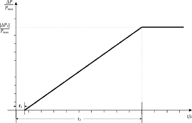
Figure 2: Active power frequency response capability of an HVDC system. ΔΡ is the change in active power triggered by the step change in frequency.
| Parameters | Time |
|---|---|
| Maximum admissible initial delay t 1 | 0,5 seconds |
| Maximum admissible time for full activation t 2, unless longer activation times are specified by the relevant TSO | 30 seconds |
Table 3: Parameters for full activation of active power frequency response resulting from frequency step change.
(e)
for HVDC systems linking various control areas or synchronous areas, in frequency sensitive mode operation the HVDC system shall be capable of adjusting full active power frequency response at any time and for a continuous time period;
(f)
as long as a frequency deviation continues active power control shall not have any adverse impact on the active power frequency response.
B.Limited frequency sensitive mode overfrequencyU.K.
1.
In addition to the requirements of Article 11 the following shall apply with regard to limited frequency sensitive mode — overfrequency (LFSM-O):
(a)
the HVDC system shall be capable of adjusting active power frequency response to the AC network or networks, during both import and export, according to Figure 3 at a frequency threshold f 1 between and including 50,2 Hz and 50,5 Hz with a droop S3 adjustable from 0,1 % upwards;
(b)
the HVDC system shall be capable of adjusting active power down to its minimum HVDC active power transmission capacity;
(c)
the HVDC system shall be capable of adjusting active power frequency response as fast as inherently technically feasible, with an initial delay and time for full activation determined by the relevant TSO and notified to the regulatory authority in accordance with the applicable national regulatory framework;
(d)
the HVDC system shall be capable of stable operation during LFSM-O operation. When LFSM-O is active, hierarchy of control functions shall be organised in accordance with Article 35.
2.
The frequency threshold and droop settings referred to in point (a) of paragraph 1 shall be determined by the relevant TSO and be notified to the regulatory authority in accordance with the applicable national regulatory framework.

Figure 3: Active power frequency response capability of HVDC systems in LFSM-O. ΔΡ is the change in active power output from the HVDC system and, depending on the operational conditions, either a decrease of import power or an increase of export power. f n is the nominal frequency of the AC network or networks the HVDC system is connected to and Δf is the frequency change in the AC network or networks the HVDC is connected to. At overfrequencies where f is above f 1 the HVDC system shall reduce active power according to the droop setting.
C.Limited frequency sensitive mode underfrequencyU.K.
1.
In addition to the requirements of Article 11, the following shall apply with regard to limited frequency sensitive mode — underfrequency (LFSM-U):
(a)
the HVDC system shall be capable of adjusting active power frequency response to the AC network or networks, during both import and export, according to Figure 4 at a frequency threshold f2 between and including 49,8 Hz and 49,5 Hz with a droop S4 adjustable from 0,1 % upwards;
(b)
in the LFSM-U mode the HVDC system shall be capable of adjusting active power up to its maximum HVDC active power transmission capacity;
(c)
the active power frequency response shall be activated as fast as inherently technically feasible, with an initial delay and time for full activation determined by the relevant TSO and notified to regulatory authority in accordance with the applicable national regulatory framework;
(d)
the HVDC system shall be capable of stable operation during LFSM-U operation. When LFSM-U is active, hierarchy of control functions shall be organised in accordance with Article 35.
2.
The frequency threshold and droop settings referred to in point (a) of paragraph 1 shall be determined by the relevant TSO and be notified to the regulatory authority in accordance with the applicable national regulatory framework.
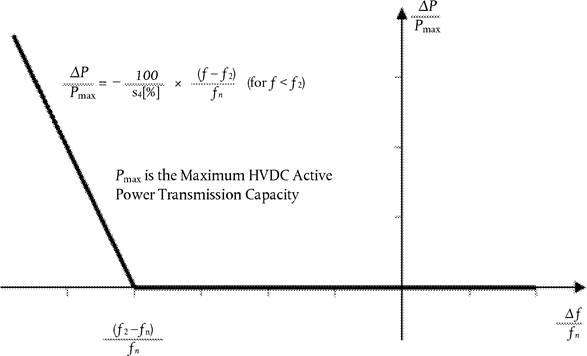
Figure 4: Active power frequency response capability of HVDC systems in LFSM-U. ΔΡ is the change in active power output from the HVDC system, depending on the operation condition a decrease of import power or an increase of export power. fn is the nominal frequency in the AC network or networks the HVDC system is connected and Δf is the frequency change in the AC network or networks the HVDC is connected. At underfrequencies where f is below f2, the HVDC system has to increase active power output according to the droop s4 .
ANNEX IIIU.K. Voltage ranges referred to in Article 18
| Synchronous Area | Voltage Range | Time period for operation |
|---|---|---|
| Continental Europe | 0,85 pu-1,118 pu | Unlimited |
| 1,118 pu-1,15 pu | To be established by each relevant system operator, in coordination with the relevant TSO but not less than 20 minutes | |
| Nordic | 0,90 pu-1,05 pu | Unlimited |
| 1,05 pu-1,10 pu | 60 minutes | |
| Great Britain | 0,90 pu-1,10 pu | Unlimited |
| Ireland and Northern Ireland | 0,90 pu-1,118 pu | Unlimited |
| Baltic | 0,85 pu-1,118 pu | Unlimited |
| 1,118 pu-1,15 pu | 20 minutes |
Table 4: Minimum time periods an HVDC system shall be capable of operating for voltages deviating from the reference 1 pu value at the connection points without disconnecting from the network. This table applies in case of pu voltage base values at or above 110 kV and up to (not including) 300 kV.
| Synchronous Area | Voltage Range | Time period for operation |
|---|---|---|
| Continental Europe | 0,85 pu-1,05 pu | Unlimited |
| 1,05 pu-1,0875 pu | To be specified by each TSO, but not less than 60 minutes | |
| 1,0875 pu-1,10 pu | 60 minutes | |
| Nordic | 0,90 pu-1,05 pu | Unlimited |
| 1,05 pu-1,10 pu | To be specified by each TSO, but not more than 60 minutes | |
| Great Britain | 0,90 pu-1,05 pu | Unlimited |
| 1,05 pu-1,10 pu | 15 minutes | |
| Ireland and Northern Ireland | 0,90 pu-1,05 pu | Unlimited |
| Baltic | 0,88 pu-1,097 pu | Unlimited |
| 1,097 pu-1,15 pu | 20 minutes |
Table 5: Minimum time periods an HVDC system shall be capable of operating for voltages deviating from the reference 1 pu value at the connection points without disconnecting from the network. This table applies in case of pu voltage base values from 300 kV to 400 kV (included).
ANNEX IVU.K. Requirements for U-Q/Pmax-profile referred to in Article 20
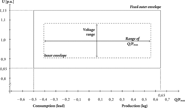
Figure 5: The diagram represents boundaries of a U-Q/Pmax-profile with U being the voltage at the connection points expressed by the ratio of its actual value to its reference 1 pu value in per unit, and Q/Pmax the ratio of the reactive power to the maximum HVDC active power transmission capacity. The position, size and shape of the inner envelope are indicative and shapes other than rectangular may be used within the inner envelope. For profile shapes other than rectangular, the voltage range represents the highest and lowest voltage points in this shape. Such a profile would not give rise to the full reactive power range being available across the range of steady-state voltages.
| Synchronous Area | Maximum range of Q/Pmax | Maximum range of steady-state Voltage level in PU |
|---|---|---|
| Continental Europe | 0,95 | 0,225 |
| Nordic | 0,95 | 0,15 |
| Great Britain | 0,95 | 0,225 |
| Ireland and Northern Ireland | 1,08 | 0,218 |
| Baltic States | 1,0 | 0,220 |
Table 6: Parameters for the Inner Envelope in the Figure.
ANNEX VU.K. Voltage-against-time-profile referred to in Article 25

Figure 6: Fault-ride-through profile of an HVDC converter station. The diagram represents the lower limit of a voltage-against-time profile at the connection point, expressed by the ratio of its actual value and its reference 1 pu value in per unit before, during and after a fault. Uret is the retained voltage at the connection point during a fault, tclear is the instant when the fault has been cleared, Urec1 and trec1 specify a point of lower limits of voltage recovery following fault clearance. Ublock is the blocking voltage at the connection point. The time values referred to are measured from tfault.
| Voltage parameters [pu] | Time parameters [seconds] | ||
|---|---|---|---|
| Uret | 0,00-0,30 | tclear | 0,14-0,25 |
| Urec1 | 0,25-0,85 | trec1 | 1,5-2,5 |
| Urec2 | 0,85-0,90 | trec2 | Trec1-10,0 |
Table 7: Parameters for Figure 6 for the fault-ride-through capability of an HVDC converter station.
ANNEX VIU.K. Frequency ranges and time periods referred to in Article 39(2)(a)
| Frequency range | Time period for operation |
|---|---|
| 47,0 Hz-47,5 Hz | 20 seconds |
| 47,5 Hz-49,0 Hz | 90 minutes |
| 49,0 Hz-51,0 Hz | Unlimited |
| 51,0 Hz-51,5 Hz | 90 minutes |
| 51,5 Hz-52,0 Hz | 15 minutes |
Table 8: Minimum time periods for the 50 Hz nominal system for which a PPM shall be capable of operating for different frequencies deviating from a nominal value without disconnecting from the network.
ANNEX VIIU.K. Voltage ranges and time periods referred to in Article 40
| Voltage Range | Time period for operation |
|---|---|
| 0,85 pu-0,90 pu | 60 minutes |
| 0,90 pu-1,10 pu | Unlimited |
| 1,10 pu-1,118 pu | Unlimited, unless specified otherwise by the relevant system operator, in coordination with the relevant TSO. |
| 1,118 pu-1,15 pu | To be specified by the relevant system operator, in coordination with the relevant TSO. |
Table 9: Minimum time periods for which a DC-connected power park module shall be capable of operating for different voltages deviating from a reference 1 pu value without disconnecting from the network where the voltage base for pu values is from 110 kV to (not including) 300 kV.
| Voltage Range | Time period for operation |
|---|---|
| 0,85 pu-0,90 pu | 60 minutes |
| 0,90 pu-1,05 pu | Unlimited |
| 1,05 pu-1,15 pu | To be specified by the relevant system operator, in coordination with the relevant TSO. Various sub-ranges of voltage withstand capability can be specified. |
Table 10: Minimum time periods for which a DC-connected power park module shall be capable of operating for different voltages deviating from a reference 1 pu value without disconnecting from the network where the voltage base for pu values is from 300 kV to 400 kV (included).

Figure 7: U-Q/Pmax-profile of a DC-connected power park module at the connection point. The diagram represents boundaries of a U-Q/Pmax-profile of the voltage at the connection point[s], expressed by the ratio of its actual value to its reference 1 pu value in per unit, against the ratio of the reactive power (Q) to the maximum capacity (Pmax). The position, size and shape of the inner envelope are indicative and other than rectangular may be used within the inner envelope. For profile shapes other than rectangular, the voltage range represents the highest and lowest voltage points. Such a profile would not give rise to the full reactive power range being available across the range of steady-state voltages.
| Range of width of Q/Pmax profile | Range of steady-state Voltage level in pu |
|---|---|
| 0-0,95 | 0,1-0,225 |
Table 11: Maximum and minimum range of both Q/Pmax and steady-state voltage for a DC-connected PPM
ANNEX VIIIU.K. Reactive power and voltage requirements referred to in Article 48
| Voltage range | Time period for operation |
|---|---|
| 0,85 pu-0,90 pu | 60 minutes |
| 0,90 pu-1,10 pu | Unlimited |
| 1,10 pu-1,12 pu | Unlimited, unless specified otherwise by the relevant system operator, in coordination with the relevant TSO. |
| 1,12 pu-1,15 pu | To be specified by the relevant system operator, in coordination with the relevant TSO. |
Table 12: Minimum time periods for which a remote-end HVDC converter station shall be capable of operating for different voltages deviating from a reference 1 pu value without disconnecting from the network where the voltage base for pu values is from 110 kV to (not including) 300 kV.
| Voltage range | Time period for operation |
|---|---|
| 0,85 pu-0,90 pu | 60 minutes |
| 0,90 pu-1,05 pu | Unlimited |
| 1,05 pu-1,15 pu | To be specified by the relevant system operator, in coordination with the relevant TSO. Various sub-ranges of voltage withstand capability may be specified. |
Table 13: Minimum time periods for which a remote-end HVDC converter station shall be capable of operating for different voltages deviating from a reference 1 pu value without disconnecting from the network where the voltage base for pu values is from 300 kV to 400 kV (included).
| Maximum range of Q/Pmax | Maximum range of steady-state voltage level in PU |
|---|---|
| 0,95 | 0,225 |
Table 14: Maximum range of both Q/Pmax and steady-state voltage for a remote-end HVDC converter station.
Options/Help
Print Options
PrintThe Whole Regulation
PrintThe Annexes only
Legislation is available in different versions:
Latest Available (revised):The latest available updated version of the legislation incorporating changes made by subsequent legislation and applied by our editorial team. Changes we have not yet applied to the text, can be found in the ‘Changes to Legislation’ area.
Original (As adopted by EU): The original version of the legislation as it stood when it was first adopted in the EU. No changes have been applied to the text.
Point in Time: This becomes available after navigating to view revised legislation as it stood at a certain point in time via Advanced Features > Show Timeline of Changes or via a point in time advanced search.
See additional information alongside the content
Geographical Extent: Indicates the geographical area that this provision applies to. For further information see ‘Frequently Asked Questions’.
Show Timeline of Changes: See how this legislation has or could change over time. Turning this feature on will show extra navigation options to go to these specific points in time. Return to the latest available version by using the controls above in the What Version box.
Opening Options
Different options to open legislation in order to view more content on screen at once
More Resources
Access essential accompanying documents and information for this legislation item from this tab. Dependent on the legislation item being viewed this may include:
- the original print PDF of the as adopted version that was used for the EU Official Journal
- lists of changes made by and/or affecting this legislation item
- all formats of all associated documents
- correction slips
- links to related legislation and further information resources
Timeline of Changes
This timeline shows the different versions taken from EUR-Lex before exit day and during the implementation period as well as any subsequent versions created after the implementation period as a result of changes made by UK legislation.
The dates for the EU versions are taken from the document dates on EUR-Lex and may not always coincide with when the changes came into force for the document.
For any versions created after the implementation period as a result of changes made by UK legislation the date will coincide with the earliest date on which the change (e.g an insertion, a repeal or a substitution) that was applied came into force. For further information see our guide to revised legislation on Understanding Legislation.
More Resources
Use this menu to access essential accompanying documents and information for this legislation item. Dependent on the legislation item being viewed this may include:
- the original print PDF of the as adopted version that was used for the print copy
- correction slips
Click 'View More' or select 'More Resources' tab for additional information including:
- lists of changes made by and/or affecting this legislation item
- confers power and blanket amendment details
- all formats of all associated documents
- links to related legislation and further information resources
 All content is available under the Open Government Licence v3.0 except where otherwise stated. This site additionally contains content derived from EUR-Lex, reused under the terms of the Commission Decision 2011/833/EU on the reuse of documents from the EU institutions. For more information see the EUR-Lex public statement on re-use.